1
Line Thermal/Dot Printer
STAR Line Mode
Command Specifications
Rev. 0.00
Star Micronics Co., Ltd.
Special Products Operating Division
Contents
1. GENERAL DESCRIPTION 2. COMMAND FUNCTION LIST
3. COMMAND DETAILS
3-1) Explanation of Terms
3-2) Exception processing
3-3) Standard Command Details
3-3-1) Font style and character set
ESC RS F n ESC GS t n
ESC GS = n1 n2 da1 da2 … dak db1 db2 … dbk
ESC R n
ESC / N
ESC SP n
ESC M
ESC P
ESC :
ESC g
ESC 6
ESC 7
3-3-2) Character Expansion Settings
ESC i n1 n2
ESC W n
ESC h n
SO
DC4
ESC SO
ESC DC4
3-3-3) Print mode
ESC E
ESC F
ESC – n ESC _ n
ESC 4
ESC 5
ESC GS 4 m n
SI
DC2
ESC RS i n
3-3-4) Line Spacing
LF
CR
ESC a n
ESC z n
ESC 0
ESC 1
ESC J n
ESC j n
ESC I n
ESC A n
ESC 2
ESC 3 n
ESC y n
3-3-5) Page Control Commands
FF
ESC C n
ESC C 0 n
VT
ESC B n1 n2 … nk NUL
ESC B NUL 3-3-6) Horizontal Direction Printing Position
ESC l n
1-1
2-1
3-1
3-1
3-2
3-3
3-3
3-3
3-4
3-5
3-6
3-7
3-7
3-8
3-8
3-9
3-9
3-10
3-10
3-11
3-11
3-12
3-13
3-14
3-14
3-15
3-15
3-16
3-16
3-17
3-18
3-19
3-20
3-20
3-21
3-23
3-23
3-24
3-25
3-25
3-25
3-26
3-27
3-27
3-28
3-28
3-29
3-29
3-30
3-30
3-31
3-31
3-32
3-32
3-33
3-34
3-35
3-36
3-36
3-37
3-37
ESC Q n
HT
ESC D n1 n2 … nk NUL
ESC D NUL ESC GS A n1 n2 ESC GS R n1 n2 ESC GS a n
3-3-7) Download
ESC & c1 c2 n d1 . . . d48
ESC & c1 c2 n ESC & NUL n1 n2 [m d1 d2 d3 d4 d5 (d6 d7)] n2 - n1 + 1
ESC % N
3-3-8) Bit Image Graphics
ESC K n1 n2 d1 … dk
ESC L n1 n2 d1 … dk
ESC k n1 n2 d1 … dk
ESC X n1 n2 d1 … dk
ESC ^ m n1 n2 d1 d2 … dk
3-3-9) Logo
ESC FS q n [x11 x12 y11 y12 d1 … dk]1 … [xn1 xn2 yn1 yn2 d1 … dk] n
ESC FS p n m ESC RS L m
3-3-10)Bar Codes ESC b n1 n2 n3 n4 d1 . . . dk RS
3-3-11) Cutter Control ESC d n
3-3-12)External Device Drive ESC BEL n1 n2
BEL
FS
SUB
EM
ESC GS BEL m t1 t2
ESC GS EM DC1 m n1 n2
ESC GS EM DC2 m n1 n2
3-3-13)Print Settings
ESC RS d n
ESC RS r n
3-3-14)Status
ESC RS a n
ESC ACK SOH
ENQ
EOT
ETB
ESC RS E n 3-3-15)Kanji Characters
ESC p
ESC q
ESC $ n ESC s n1 n2
ESC t n1 n2
ESC r c1 c2 d1 … dk
ESC u n
ESC x n
ESC w n
3-3-16)Others
RS
CAN
ESC U n
ESC GS # m N n1 n2 n3 n4 LF NUL
ESC # @ LF NUL
ESC # N ? n1 n2 n3 n4 LF NUL
3-38
3-39
3-39
3-40
3-40
3-41
3-42
3-43
3-43
3-44
3-45
3-47
3-48
3-48
3-50
3-51
3-52
3-53
3-54
3-54
3-56
3-57
3-58
3-58
3-60
3-60
3-61
3-61
3-62
3-62
3-63
3-63
3-64
3-65
3-66
3-67
3-67
3-68
3-69
3-69
3-70
3-70
3-71
3-71
3-72
3-73
3-73
3-73
3-74
3-75
3-76
3-77
3-79
3-80
3-81
3-82
3-82
3-82
3-84
3-85
3-86
3-86
4. CHARACTER CODE TABLES
5. APPENDIX
5-1) Appendix 1: Bar Code Specification Details <Thermal>
5-1-1) Code 39
5-1-2) Interleaved 2 of 5
5-1-3) JAN/EAN/UPC
5-1-4) Code 128
5-1-5) Code 93
5-1-6) NW7 (CODERBAR)
5-2) Appendix 2 – Status Specifications <Shared>
5-2-1) ENQ Command Status
5-2-2) EOT Command Status
5-2-3) Automatic Status
5-2-4) Printer Status Transmission Specification when using Ethernet and Wireless LAN Interfaces 5-3) Appendix 3 – Blank Code Page Configuration <Thermal> 5-4) Appendix
CharacterCount
erson
6. SPECIAL APPENDIX COMMAND LIST BY MODEL
7. SPECIAL APPENDIX COMMAND FUNCTION LIST
7-1) HSP7000
7-1-1) Setting Command List 7-1-2) Execution Command List 4-1
5-1
5-1
5-1
5-1
5-2
5-3
5-5
5-5
5-6
5-6
5-6
5-7
5-12
5-14
5-16
6-1
7-1
7-1
7-1
7-6
Rev. 0.00
1. GENERAL DESCRIPTION
This specifications document describes the command specifications for the STAR MODE on hybrid printers.
Information contained herein applies to models with the following conditions.
• Hybrid printers
• Interfaces:
- Parallel
• RS-232C
• USB
- Ethernet
< Applicable Models:>
• HSP7000
STAR LIne Mode Command Specifications
1-1
Rev. 0.00
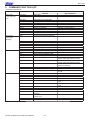
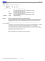
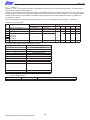
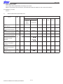
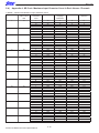
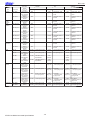
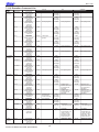
2. COMMAND FUNCTION LIST
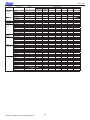
• Standard Commands
Class
Font style
and character
set
Character
expansion
settings
Print modes
Line spacing
Commands
Name
Thermal
Slip, Validation
ESC RS F
ESC GS t
Select font
Select code page
←
ESC GS =
ESC R
ESC /
ESC SP
ESC M
ESC P
ESC :
ESC g
ESC 6
ESC 7
ESC i
Write blank code page data
Specify international character set
Specify/cancel slash zero
Set ANK right space
Specify 12 dot pitch
Specify 15 dot pitch
Specify 16 dot pitch
Specify 14 dot pitch
Set/cancel the double wide/high
←
←
←
←
Specify 7 x 9 font (half dots)
Specify 5 x 9 font (2P-1)
Specify 5 x 9 font (3P-1)
-
ESC W
ESC h
SO
DC4
ESC SO
ESC DC4
ESC E
ESC F
ESC ESC _
ESC 4
Specify/cancel expanded wide
Specify/cancel expanded high
Set double wide printing
Cancel expanded wide
Set double high
Cancel expanded high
Select emphasized printing
Cancel emphasized printing
Select/cancel underline mode
Select/cancel upperline mode
Selects white/black inversion
ESC 5
Cancel white/black inversion
ESC GS 4
-
SI
DC2
ESC RS i
Select upside-down printing
Cancel upside-down printing
-
LF
CR
ESC a
ESC z
ESC 0
Line feed
Line feed
Feed paper n lines
Select line feed amount
Specify line feed to 3 mm
ESC 1
Specify line feed to 3 mm
ESC J
ESC j
ESC I
ESC A
n/4 mm line feed
n/8mm line feed
Specify line feed amount of 3
mm/4mm
Specify line feed amount (Defined
by ESC A n)
-
←
←
←
←
←
←
←
←
Select white/black inversion red/
black colors (substitute function)
Cancel white/black inversion red/
black colors (substitute function)
Select red/black substitute function
[ESC 4/5 setting]
←
←
Specify/cancel character rotated
mode
←
←
←
←
Specify line feed amount of 1/8
inch
Specify line feed amount of 7/72
inch
n/72 inch paper feed
Reverse paper feed
n/144 inch paper feed
Define n/72 inch pitch line feed
ESC 2
ESC 3
ESC y
STAR LIne Mode Command Specifications
2-1
←
Specify n/216 inch paper feed
Specify n/144 inch paper feed
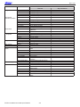
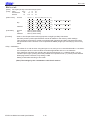
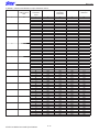
Rev. 0.00
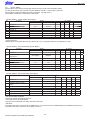
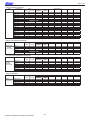
Class
Page control
Horizontal
direction position
Download
Bit image
Graphics
Logos
Bar Codes
Cutter control
External device
drive
Print Setting
Status
Commands
Name
Thermal
FF
ESC C
ESC C 0
VT
ESC B
ESC I
Form feed
Set page length to n lines
Set page length in n x 24 mm units
Feed paper to vertical tab position
Set vertical tab position
Set left margin
←
ESC Q
HT
ESC D
ESC GS A
ESC GS R
ESC GS a
ESC &
Set right margin
Move horizontal tab
Set/cancel horizontal tab
Move absolute position
Move relative position
Specify position alignment
Register/delete download
characters
Set/cancel download characters
Standard density bit image
High density bit image
Fine bit image
Fine bit image
Register logo
Print logo
Logo batch control
Print bar code
Auto-cutter
Set external drive device 1 pulse
width
External device 1 drive instruction
External device 1 drive instruction
External device 2 drive instruction
External device 2 drive instruction
Ring buzzer
Set external buzzer drive pulse
condition
Execute external buzzer drive
Set print density
Set printing speed
Set status transmission conditions
Real-time printer status
(ASB Status)
Real-time printer status (1)
Real-time printer status (2)
Update of ETB status
Clear ETB counter, initialize ETB
status
←
←
←
←
←
←
←
ESC %
ESC K
ESC L
ESC k
ESC X
ESC ^
ESC FS q
ESC FS p
ESC RS L
ESC b
ESC d
ESC BEL
BEL
FS
SUB
EM
ESC GS BEL
ESC GS EM DC1
ESC GS EM DC2
ESC RS d
ESC RS r
ESC RS a
ESC ACK SOH
ENQ
EOT
ETB
ESC RS E
STAR LIne Mode Command Specifications
2-2
Slip, Validation
←
←
←
9 Dot bit image
←
←
←
←
←
←
←
←
←
←
←
←
←
←
←
←
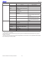
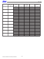
Rev. 0.00
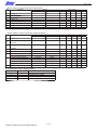
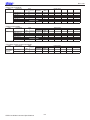
Class
Kanji Character
Commands
ESC u
Name
Thermal
Set JIS Kanji Character mode
Cancel JIS Kanji Character mode
Set/cancel JIS Kanji Character
mode
Set two-byte Kanji characters left/
right spaces
Set single-byte Kanji characters
left/right spaces
Register Chinese download
characters
-
ESC x
-
ESC w
-
RS
CAN
Cancel print data and initialize
commands
Initialize commands
Set memory switch
Initialize all memory switches
Inquire memory switch setting
contents
Inquire printer version
Reset printer
Printer deselect
Select printer
ESC p
ESC q
ESC $
ESC s
ESC t
ESC r
Others
ESC @
ESC U
ESC GS #
ESC # @
ESC # N ?
ESC # *
ESC ?
DC3
DC1
←
←
←
Slip, Validation
←
←
←
Specify two-byte 16 x 16 dot Kanji
Character (Single density/double
density)
Specify expanded Kanji characters
(Double tall/double high & wide)
Specify expanded Kanji characters
(batch double tall/double high &
wide)
Ring buzzer
←
←
Select printing direction
←
←
←
←
←
←
←
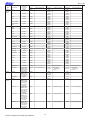
(*) Kanji character commands
• Kanji character control commands are ignored on printers not installed with Kanji character fonts (those intended for overseas).
• All Kanji control commands are ignored if the specification for the location of use is specified as SBCS (single
byte countries) by the memory switch.
STAR LIne Mode Command Specifications
2-3
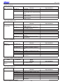
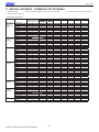
Rev. 0.00
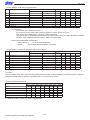
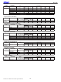
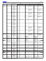
• Raster Related Commands
Class
Raster
commands
Commands
ESC * r R
ESC * r A
ESC * r B
ESC * r C
ESC * r D
ESC * r E
ESC * r F
ESC * r P
ESC * r Q
ESC * r m l
ESC * r m r
ESC * r T
ESC * r K
b n1 n2 d1 … dk
k n1 n2 d1 … dk
ESC * r Y
ESC FF NUL
ESC FF EOT
ESC * r N
ESC * r V
Name
Thermal
Initialize raster mode
Enter raster mode
Quit raster mode
Clear raster data
Drawer drive
Set raster EOT mode
Set raster FF mode
Set raster page length
Set raster print quality
Set raster left margin
Set raster right margin
Set raster top margin
Set raster print color
Transfer raster data (auto line
feed)
Transfer raster data
Move vertical direction position
(Line feed for specified dots)
Execute form feed mode
Execute EOT mode
Discard specified byte count of
data
Execute external buzzer drive
-
Slip, Validation
-
• Black Mark Related Commands
Class
Black mark
Related
commands
Commands
Name
Thermal
ESC d
FF
Auto-cutter:
Execute top of form
-
ESC C
ESC C 0
VT
ESC B
Set page length to n lines
Set page length in n x 24 mm units
Feed paper to vertical tab position
Set vertical tab position
-
Slip, Validation
• 2-Color Printing Related Commands
Class
Commands
2-Color Printing
ESC RS c
Related
commands
ESC RS C
ESC 4
ESC 5
ESC RS d
ESC RS r
ESC FS q
ESC FS p
Name
Thermal
Specify printing color in 2 color
printing mode
Select/cancel 2-color printing
mode
Specify white/black inversion or
printing color red
Cancel white/black inversion or
specify printing color black
Set print density
Set printing speed
Register logo
Print logo
STAR LIne Mode Command Specifications
2-4
-
Slip, Validation
Select white/black inversion red/
black colors (substitute function)
Cancel white/black inversion red/
black colors (substitute function)
←
←
Rev. 0.00
• Mark Commands
Class
Mark Commands
Commands
ESC GS * 0
ESC GS * 1
ESC GS * 2
ESC GS * W
ESC GS * C
Name
Thermal
Print mark
Specify mark height and line feed
At each mark number
Specify mark color, mark horizontal
width
Register mark format to nonvolatile memory
Initialize mark format from nonvolatile memory
-
Slip, Validation
-
• Auto Logo Commands
Class
Auto Logo
Commands
Commands
ESC GS / W
ESC GS / C
ESC GS / 1
ESC GS / 2
ESC GS / 3
ESC GS / 4
ESC GS / 5
ESC GS / 6
Name
Thermal
Register Auto Logo setting to nonvolatile memory
Initialize Auto Logo setting from
non-volatile memory
Set ON/OFF for Auto Logo function
Set command characters
Set user macro 1
Set user macro 2
Set command character switching
method
Set partial cut just prior to Auto
Logo printing
-
Slip, Validation
-
• PDF417 Commands
Class
PDF417
Commands
Commands
ESC GS x S 0
Name
Thermal
Slip, Validation
Set PDF417 bar code size
-
ESC GS x S 1
ESC GS x S 2
Set PDF417 ECC (security level)
Set PDF417 module x direction
size
-
ESC GS x S 3
ESC GS x D
ESC GS x P
ESC GS x I
Set PDF417 module aspect ratio
Set PDF417 bar code data
Print PDF417 bar code
Get PDF417 bar code expansion
information
←
• Print Start Trigger Control Commands
Class
Print starting
trigger
Commands
ESC GS g 0
ESC GS g 1
Name
Thermal
Slip, Validation
Print starting trigger
-
Set print start timer
-
• QR Code Commands
Class
QR Code
Commands
ESC GS y S 0
ESC GS y S 1
ESC GS y S 2
ESC GS y D 1
ESC GS y D 2
ESC GS y P
ESC GS y I
Name
Thermal
Set QR code model
Set QR code mistake correction level
Set QR code cell size
Set QR code data (auto setting)
Set QR code data (manual setting)
Print QR code
Get QR code expansion
information
STAR LIne Mode Command Specifications
2-5
←
Slip, Validation
Rev. 0.00
• Page Function Commands
Class
Page Function
Commands
ESC GS h 0
ESC GS h 1
Name
Thermal
180˚ inversion function Water mark function
-
Slip, Validation
• Slip/Validation Function Commands
Class
Slip Function
Commands
ESC SI
ESC FF
ESC VT
ESC EM
ESC US
-
Name
Thermal
Slip, Validation
Slip/Validation Function
Set slip/validation automatic clamp
• Page Mode Commands
Class
Page mode
Commands
FF
ESC n
ESC !
ESC *
ESC T
-
Name
Thermal
Slip, Validation
Batch print page data
Select page mode
Select line mode
Set page mode print region
Sets page mode print direction
• Station Selection Command
Class
Station Selection
Commands
ESC + A
Name
Thermal
Station Selection
←
Slip, Validation
• Presenter Related Commands
Class
Presenter
Related
commands
Commands
Name
Thermal
ESC SYN 0
-
-
ESC SYN 1
-
-
ESC SYN 3
ESC SYN 4
-
-
Name
Thermal
MICR function
←
Slip, Validation
• MICR Related Command
Class
MICR
Commands
ESC FS M
STAR LIne Mode Command Specifications
2-6
Slip, Validation
Rev. 0.00
3. COMMAND DETAILS
3-1) Explanation of Terms
• Reception buffer
The buffer for storing data (reception data) received from the host, as it is called the reception buffer.
Reception data is temporarily stored in the reception buffer, then processed sequentially.
• Line buffer
The buffer for storing image data for printing is called the line buffer.
• Line buffer full
The state in which the buffer has no more space available is called line buffer full. When the buffer is full in line mode,
data in the line buffer is printed and a line feed is performed when new print data is processed. This is the same as a
Line Feed. When the line buffer is full in the page mode, the printer move the print position to the head of the next line
then starts with the new print data.
• Top of line
The top of line is a state that satisfies the following conditions.
A. There is currently no print data in the line buffer.
B. The position is not specified with the horizontal direction position command.
• Printable region
This is the maximum printable area with the printer’s specifications.
• Print region
This is the printing area specified by a command.(Print region ≤ printable region)
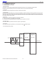
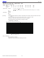
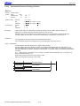
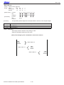
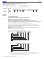
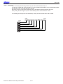
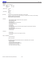
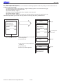
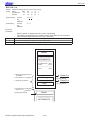
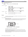
• Print data expansion position
40 dot
20 dot
4dot
Ay
STAR Line Mode Command Specifications
Double
high
Expanded
24 dot
Bit image
Bar Code
Height h dot
Bar Code
Base Line
8 dot
3-1
Rev. 0.00
3-2) Exception processing
1) Undefined codes
Codes from <00>H to <1F>H are targeted. When codes not defined as commands in this region are received, they are
discarded.
(Ex.) If processing the data string of <30>H<31>H<03>H<32>H<0A>H<33>H, the printer will discard <03>H as an
undefined code.
2) Undefined commands
When data continuing the codes of ESC, FS, GS, DLE are codes not defined as commands, ESC, FS,GS and subsequent codes are discarded.
(Ex.) If processing the data string of <30>H<1B>H<22>H<31>H<32>H, the printer will read and discard
<1B>H<22>H as an undefined command.
3) Settings outside of the defined area
Processing values outside of the defined area in commands accompanying arguments, those commands are ignored
and the preset values are unchanged.
(Ex.:)
If processing the data string of <1B>H<52>H<15>H, the printer will discard the data string of <1B>H<52>H<15>H because although <1B>H<52>H is defined as a commands (ESC R) , the argument
<15>H is outside of the definition. Therefore, the international character set that is already set experiences no
change.
STAR LIne Mode Command Specifications
3-2
Rev. 0.00
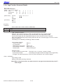
3-3) Standard Command Details
3-3-1) Font style and character set
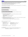
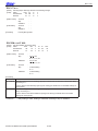
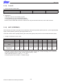
ESC RS F n
[Name]
[Code]
Select font
ASCII
Hexadecimal
Decimal
[Defined Area]
[Initial Value]
[Function]
<Thermal>
n
0
1
16
ESC
1B
27
Thermal
Slip
Validation
Thermal
Slip
Validation
:
:
:
:
:
:
RS
1E
30
F
46
70
n
n
n
0 ≤ n ≤ 1, n = 16
n=0
-
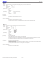
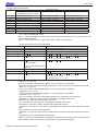
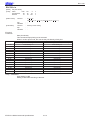
Select font
Font
Font-A (12 x 24 dots)
Font-B (9 x 24 dots)
OCR-B (16 x 24 dots)
When OCR-B font is selected, the following functions are invalid.
• Code Pages
• Blank Code Pages
• International Characters
• Slashed Zero
When using the OCR-B font to read characters using a scanner, cancel adornment, expansion and
external character settings. Also, check the OCR-B font by actual use.
<Slip>, <Validation>
Only setting is valid
Setting is valid after switching to thermal.
STAR Line Mode Command Specifications
3-3
Rev. 0.00
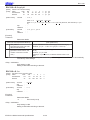
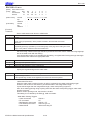
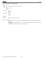
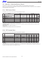
ESC GS t n
[Name]
[Code]
Select code page
ASCII
ESC
Hexadecimal
1B
Decimal
27
[Defined Area]
[Initial Value]
[Function]
n
0
1
2
3
4
5
6
7
8
9
10
11
12
13
14
15
16
17
18
19
20
21
Thermal
Slip
Validation
Thermal
Slip
Validation
GS
1D
29
:
:
:
:
:
:
t
74
116
n
n
n
0 ≤ n ≤ 21, 32 ≤ n ≤ 34, 64 ≤ n ≤ 79, n = 255
0 ≤ n ≤ 21, 32 ≤ n ≤ 34, 64 ≤ n ≤ 79, n = 255
0 ≤ n ≤ 21, 32 ≤ n ≤ 34, 64 ≤ n ≤ 79, n = 255
Memory switch setting, when set to DBCS, Japanese characters normal katakana are fixed.
Memory switch setting, when set to DBCS, Japanese characters normal katakana are fixed.
Memory switch setting, when set to DBCS, Japanese characters normal katakana are fixed.
Specifies code page
When installed with Japanese language characters and DBCS setting, this command is ignored.
Code Page
Normal
CodePage437 (USA,Std. Europe)
Katakana
CodePage437 (USA, Std. Europe)
Codepage 858 (Multilingual)
Codepage 852 (Latin-2)
Codepage 860 (Portuguese)
Codepage 861 (Icelandic)
Codepage 863 (Canadian French)
Codepage 865 (Nordic)
Codepage 866 (Cyrillic Russian)
Codepage 855 (Cyrillic Bulgarian)
Codepage 857 (Turkish)
Codepage 862 (Israel (Hebrew) )
Codepage 864 (Arabic)
Codepage 737 (Greek)
Codepage 851 (Greek)
Codepage 869 (Greek)
Codepage 928 (Greek)
Codepage 772 (Lithuanian)
Codepage 774 (Lithuanian)
Codepage 874 (Thai)
n
32
33
34
64
65
66
67
68
69
70
71
72
73
74
75
76
77
78
79
255
Code Page
Code Page 1252 (Windows Latin -1)
Codepage 1250 (Windows Latin-2)
Codepage 1251 (Windows Cyrillic)
Codepage 3840 (IBM-Russian)
Codepage 3841 (Gost)
Codepage 3843 (Polish)
Codepage 3844 (CS2)
Codepage 3845 (Hungarian)
Codepgae 3846 (Turkish)
Codepage 3847 (Brazil-ABNT)
Codepage 3848 (Brazil-ABICOMP)
Codepage 1001 (Arabic)
Codepage 2001 (Lithuanian-KBL)
Codepage 3001 (Estonian-1)
Codepage 3002 (Estonian-2)
Codepage 3011 (Latvian-1)
Codepage 3012 (Latvian-2)
Codepage 3021 (Bulgarian)
Codepage 3041 (Maltese)
Empty page
(Note)The settings using this command are valid for all stations and modes.
STAR LIne Mode Command Specifications
3-4
Rev. 0.00
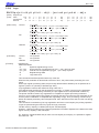
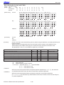
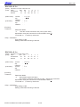
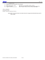
ESC GS = n1 n2 da1 da2 … dak db1 db2 … dbk
[Name]
[Code]
Write blank code page data
ASCII
ESC
GS
Hexadecimal
1B
1D
Decimal
27
29
=
3D
61
n1
n1
n1
n2
n2
n2
da1
da1
da1
da2
da2
da2
..
..
..
dak
dak
dak
db1
db1
db1
db2
db2
db2
..
..
..
dbk
dbk
dbk
[Defined Area]
Thermal
:
n1 = 0, n2 = 48, 1 ≤ (n1 + n2 x 256)
[Initial Value]
Slip
Validation
Thermal
Slip
Validation
:
:
:
:
:
0 ≤ da ≤ 255 (Font-A data), db = 0 (Star mode does not have Font-B), k = (n1 + n2 x 256)
-
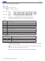
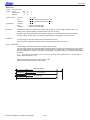
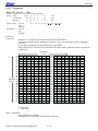
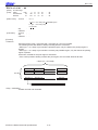
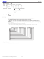
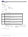
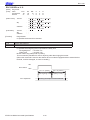
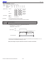
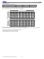
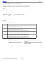
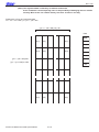
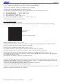
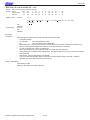
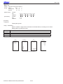
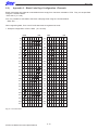
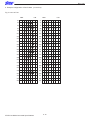
[Function]
A blank code page indicates a character code table where character codes from 80h to FFh are all
blank.
A blank code page can be selected using the ESC GS t n command n = 255.
The printer is reset when writing with this command is completed.
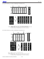
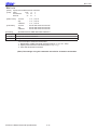
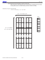
[Font-A Data Format Vertical 24 dots x Horizontal 12 dots]
• = Data region/ ○= Zero data
(Font - A Data Format
MSB
Da1
●
●
Da3
●
●
Da5
●
●
Da7
●
●
Da9
●
●
Da11
●
●
Da13
●
●
Da15
●
●
Da17
●
●
Da19
●
●
Da21
●
●
Da23
●
●
Da25
●
●
Da27
●
●
Da29
●
●
Da31
●
●
Da33
●
●
Da35
●
●
Da37
●
●
Da39
●
●
Da41
●
●
Da43
●
●
Da45
●
●
Da47
●
●
Vertical 24 dot x Horizontal 12 dot)
LSB
●
●
●
●
●
●
●
●
●
●
●
●
●
●
●
●
●
●
●
●
●
●
●
●
●
●
●
●
●
●
●
●
●
●
●
●
●
●
●
●
●
●
●
●
●
●
●
●
●
●
●
●
●
●
●
●
●
●
●
●
●
●
●
●
●
●
●
●
●
●
●
●
●
●
●
●
●
●
●
●
●
●
●
●
●
●
●
●
●
●
●
●
●
●
●
●
●
●
●
●
●
●
●
●
●
●
●
●
●
●
●
●
●
●
●
●
●
●
●
●
●
●
●
●
●
●
●
●
●
●
●
●
●
●
●
●
●
●
●
●
●
●
●
●
= Data Region /
Da2
Da4
Da6
Da8
Da10
Da12
Da14
Da16
Da18
Da20
Da22
Da24
Da26
Da28
Da30
Da32
Da34
Da36
Da38
Da40
Da42
Da44
Da46
Da48
MSB
●
●
●
●
●
●
●
●
●
●
●
●
●
●
●
●
●
●
●
●
●
●
●
●
●
●
●
●
●
●
●
●
●
●
●
●
●
●
●
●
●
●
●
●
●
●
●
●
●
●
●
●
●
●
●
●
●
●
●
●
●
●
●
●
●
●
●
●
●
●
●
●
= Zero Data
<Slip>, <Validation>
Only registration is possible.
Registration data is printable after switching to thermal.
STAR Line Mode Command Specifications
3-5
●
●
●
●
●
●
●
●
●
●
●
●
●
●
●
●
●
●
●
●
●
●
●
●
LSB
○
○
○
○
○
○
○
○
○
○
○
○
○
○
○
○
○
○
○
○
○
○
○
○
○
○
○
○
○
○
○
○
○
○
○
○
○
○
○
○
○
○
○
○
○
○
○
○
○
○
○
○
○
○
○
○
○
○
○
○
○
○
○
○
○
○
○
○
○
○
○
○
○
○
○
○
○
○
○
○
○
○
○
○
○
○
○
○
○
○
○
○
○
○
○
○
Rev. 0.00
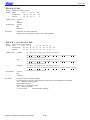
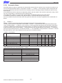
ESC R n
[Name]
[Code]
Specify international character set
ASCII
ESC
R
n
Hexadecimal
1B 52
n
Decimal
27 82
n
[Defined Area]
[Initial Value]
Thermal
Slip
Validation
Thermal
:
:
:
:
0 ≤ n ≤ 14, n = 64, 48 ≤ N ≤ 57 (”0” ≤ n ≤ “9”), 65 ≤ n ≤ 69 (”A” ≤ n ≤ “E”)
0 ≤ n ≤ 14, n = 64, 48 ≤ N ≤ 57 (”0” ≤ n ≤ “9”), 65 ≤ n ≤ 69 (”A” ≤ n ≤ “E”)
0 ≤ n ≤ 14, n = 64, 48 ≤ N ≤ 57 (”0” ≤ n ≤ “9”), 65 ≤ n ≤ 69 (”A” ≤ n ≤ “E”)
Memory switch setting
Slip
:
When installed with Japanese language characters and DBCS setting: Fixed at n = 8
Memory switch setting
Validation
:
When installed with Japanese language characters and DBCS setting: Fixed at n = 8
Memory switch setting
When installed with Japanese language characters and DBCS setting: Fixed at n = 8
[Function]
n
0, 48
1, 49
2, 50
3, 51
4, 52
5, 53
6, 54
7, 55
8, 56
9, 57
10, 65
11, 66
12, 67
13, 68
14, 69
64
Specifies international characters
See each printer’s product specifications manual for details on the memory switch settings.
International Characters
USA
France
Germany
UK
Denmark
Sweden
Italy
Spain
Japan
Norway
Denmark II
Spain II
Latin America
Korea
Ireland
Legal
When installed with Japanese language characters and DBCS setting, this command is ignored.
Note that if the code page 3041 (Maltese) is selected for the code page, international characters are
disabled and the specified characters of code page 3041 are printed.
At that time, the specified international character setting is valid when changed to a different code
page.
(Note)The settings using this command are valid for all stations and modes.
STAR LIne Mode Command Specifications
3-6
Rev. 0.00
ESC / N
[Name]
[Code]
Specify/cancel slash zero
ASCII
ESC
/
Hexadecimal
1B 2F
Decimal
27 47
[Defined Area]
[Initial Value]
[Function]
n
0, 48
1, 49
Thermal
Slip
Validation
Thermal
Slip
Validation
:
:
:
:
:
:
n
n
n
n = 0, 1, 48, 49
n = 0, 1, 48, 49
n = 0, 1, 48, 49
Memory switch setting
Memory switch setting
Memory switch setting
Specifies and cancels slash zeros.
See each printer’s product specifications manual for details on the memory switch settings.
International Characters
Cancels slash zero
Specifies slash zero
Note that if the code page 3041 (Maltese) is selected for the code page, slash zero is invalid, and
normal zeros will be printed.
At that time, the specified slash zero setting is valid when changed to a different code page.
(Note)The settings using this command are valid for all stations and modes.
ESC SP n
[Name]
[Code]
Set ANK right space
ASCII
ESC
Hexadecimal
1B
Decimal
27
[Defined Area]
[Initial Value]
[Function]
<Thermal>
Thermal
Slip
Validation
Thermal
Slip
Validation
SP
20
32
:
:
:
:
:
:
n
n
n
0 ≤ n ≤ 15, 48 ≤ N ≤ 57 (”0” ≤ n ≤ “9”), 65 ≤ n ≤ 70 (”A” ≤ n ≤ “F”)
0 ≤ n ≤ 15, 48 ≤ N ≤ 57 (”0” ≤ n ≤ “9”), 65 ≤ n ≤ 70 (”A” ≤ n ≤ “F”)
0 ≤ n ≤ 15, 48 ≤ N ≤ 57 (”0” ≤ n ≤ “9”), 65 ≤ n ≤ 70 (”A” ≤ n ≤ “F”)
Memory switch setting
n=0
n=0
Specifies the right space for ANK 12 x 24 dot fonts in n dots.
Character spacing can be specified also with the following commands.
• Specify 12 dot pitch (ESC M)
• Specify 14 dot pitch (ESC g)
• Specify 15 dot pitch (ESC P)
• Specify 16 dot pitch (ESC :)
<Slip>, <Validation>
Specifies right space of characters with n half dots.
When in horizontal double-wide printing, the right space is also double.
(Note)The settings by this command are valid for all stations.
Setting value is shared when thermal and slip, validation line mode is selected.
The setting value when slip, validation page mode is selected is shared only when slip,
validation page mode is selected.
STAR Line Mode Command Specifications
3-7
Rev. 0.00
ESC M
[Name]
[Code]
(Thermal) Specify 12 dot pitch/(Slip) specify 7 x 9 font (half dots) (default)
ASCII ESC
M
Hexadecimal
1B
4D
Decimal
27
77
[Defined Area]
[Initial Value]
[Function]
<Thermal>
Thermal
Slip
Validation
Thermal
Slip
Validation
:
:
:
:
:
:
Memory switch setting
-
Specifies the right space for ANK 12 x 24 dot fonts in 0 dots.
<Slip>, <Validation>
Specifies 7 x 9 (half) dot font.
Sets the number of printable digits in one line to [total half dot count/(10 + character right space
amount).
When page mode is selected, it is fixed at 5 x 9 fonts, and only the setting is valid.
Setting is valid after switching to line mode.
(Note)The settings by this command are valid for all stations.
ESC P
[Name]
[Code]
(Thermal) Specify 15 dot pitch/(Slip) specify 5 x 9 font (2P-1)
ASCII
ESC
P
Hexadecimal
1B 50
Decimal
27 80
[Defined Area]
[Initial Value]
[Function]
<Thermal>
Thermal
Slip
Validation
Thermal
Slip
Validation
:
:
:
:
:
:
Memory switch setting
-
Specifies the right space for ANK 12 x 24 dot fonts in 3 dots.
<Slip>, <Validation>
Specifies 5 x 9 (2 pulse = 1) dot fonts.
Sets the number of printable digits in one line to [total half dot count/(12 + character right space
amount).
(Note)The settings by this command are valid for all stations.
STAR LIne Mode Command Specifications
3-8
Rev. 0.00
ESC :
[Name]
[Code]
(Thermal) Specify 16 dot pitch/(Slip) specify 5 x 9 font (3P-1)
ASCII
ESC
:
Hexadecimal
1B 3A
Decimal
27 58
[Defined Area]
[Initial Value]
[Function]
<Thermal>
Thermal
Slip
Validation
Thermal
Slip
Validation
:
:
:
:
:
:
Memory switch setting
-
Specifies the right space for ANK 12 x 24 dot fonts in 4 dots.
<Slip>, <Validation>
Specifies 5 x 9 (3 pulse = 1) dot fonts.
Sets the number of printable digits in one line to [total half dot count/(18 + character right space
amount).
(Note)The settings by this command are valid for all stations.
ESC g
[Name]
[Code]
Specify 14 dot pitch
ASCII
ESC
Hexadecimal
1B
Decimal
27
[Defined Area]
[Initial Value]
[Function]
<Thermal>
Thermal
Slip
Validation
Thermal
Slip
Validation
:
:
:
:
:
:
g
67
103
Memory switch setting
-
Specifies rights space for the ANK 12 x 24 dot fonts to 2 dots.
<Slip>, <Validation>
Only setting is valid
Setting is valid after switching to thermal.
STAR Line Mode Command Specifications
3-9
Rev. 0.00
ESC 6
[Name]
[Code]
Specify IBM character set #2
ASCII
ESC
6
Hexadecimal
1B 36
Decimal
27 54
[Defined Area]
[Initial Value]
[Function]
ESC 7
[Name]
[Code]
Thermal
Slip
Validation
Thermal
Slip
Validation
:
:
:
:
:
:
-
Two bytes ignored
Specify IBM character set #1
ASCII
ESC
7
Hexadecimal
1B 37
Decimal
27 55
[Defined Area]
[Initial Value]
[Function]
Thermal
Slip
Validation
Thermal
Slip
Validation
:
:
:
:
:
:
-
Two bytes ignored
STAR LIne Mode Command Specifications
3-10
Rev. 0.00
3-3-2) Character Expansion Settings
ESC i n1 n2
[Name]
[Code]
Set/cancel the double wide/high
ASCII
ESC
i n1
Hexadecimal
1B
69 n1
Decimal
27 105 n1
[Defined Area]
[Initial Value]
[Function]
Thermal
Slip
Validation
Thermal
Slip
Validation
:
:
:
:
:
:
n2
n2
n2
0 ≤ n1 ≤ 5, 48 ≤ n1 ≤ 53(“0” ≤ n1 ≤ “5”), 0 ≤ n2 ≤ 5, 48 ≤ n2 ≤ 53(“0” ≤ n2 ≤ “5”)
0 ≤ n1 ≤ 5, 48 ≤ n1 ≤ 53(“0” ≤ n1 ≤ “5”), 0 ≤ n2 ≤ 5, 48 ≤ n2 ≤ 53(“0” ≤ n2 ≤ “5”)
0 ≤ n1 ≤ 5, 48 ≤ n1 ≤ 53(“0” ≤ n1 ≤ “5”), 0 ≤ n2 ≤ 5, 48 ≤ n2 ≤ 53(“0” ≤ n2 ≤ “5”)
n1 = 0 (Double high cancelled), n2 = 0 (Double wide cancelled)
n1 = 0 (Double high cancelled), n2 = 0 (Double wide cancelled)
n1 = 0 (Double high cancelled), n2 = 0 (Double wide cancelled)
Specifies/cancels double high/wide for ANK characters and Kanji characters.
This command is ignored if either n1 or n2 is outside of the defined area.
<Thermal>
n1
0, 48
1, 49
2, 50
3, 51
4, 52
5, 53
Cancel expanded high
Specifies 2x expansion
Specifies 3x expansion
Specifies 4x expansion
Specifies 5x expansion
Specifies 6x expansion
Expanded high
n2
0, 48
1, 49
2, 50
3, 51
4, 52
5, 53
Cancel expanded wide
Specifies 2x wide expansion
Specifies 3x wide expansion
Specifies 4x wide expansion
Specifies 5x wide expansion
Specifies 6x wide expansion
Expanded wide
<Slip>, <Validation>
n1
0, 48
1 ≤ n1 ≤ 5, 49 ≤ n1 ≤ 53
Cancel expanded high
Specifies 2x expansion
Expanded high
n2
0, 48
1 ≤ n2 ≤ 5, 49 ≤ n2 ≤ 53
Cancel expanded wide
Specifies 2x wide expansion
Expanded wide
However, in standard specifications, only the line feed amount is doubled for font configurations of 6
x 12 IBM block graphic characters.
When slip or validation is selected, and more than double is specified, printing is doubled for every
setting.
Setting more than triple is valid after switching to thermal.
(Note)The settings using this command are valid for all stations and modes.
STAR Line Mode Command Specifications
3-11
Rev. 0.00
ESC W n
[Name]
[Code]
Specify/cancel expanded wide
ASCII
ESC
W
n
Hexadecimal
1B 57
n
Decimal
27 87
n
[Defined Area]
[Initial Value]
[Function]
Thermal
Slip
Validation
Thermal
Slip
Validation
:
:
:
:
:
:
0 ≤ n ≤ 5, 48 ≤ n ≤ 53, (“0” ≤ n ≤ “5”)
0 ≤ n ≤ 5, 48 ≤ n ≤ 53, (“0” ≤ n ≤ “5”)
0 ≤ n ≤ 5, 48 ≤ n ≤ 53, (“0” ≤ n ≤ “5”)
n = 0 (Double wide cancelled)
n = 0 (Double wide cancelled)
n = 0 (Double wide cancelled)
Specifies/cancels double wide for ANK characters and Kanji characters.
<Thermal>
n
0, 48
1, 49
2, 50
3, 51
4, 52
5, 53
Expanded wide
Cancel expanded wide
Specifies 2x wide expansion
Specifies 3x wide expansion
Specifies 4x wide expansion
Specifies 5x wide expansion
Specifies 6x wide expansion
<Slip>, <Validation>
n
0, 48
1 ≤ n ≤ 5 49 ≤ n ≤ 53
Function
Cancels double wide expanded printing
Specifies double wide expanded printing
When slip or validation is selected, and more than double is specified, printing is doubled for every
setting.
Setting more than triple is valid after switching to thermal.
(Note)The settings using this command are valid for all stations and modes.
STAR LIne Mode Command Specifications
3-12
Rev. 0.00
ESC h n
[Name]
[Code]
Specify/cancel expanded high
ASCII
ESC
h
Hexadecimal
1B
68
Decimal
27 104
[Defined Area]
[Initial Value]
[Function]
Thermal
Slip
Validation
Thermal
Slip
Validation
:
:
:
:
:
:
n
n
n
0 ≤ n ≤ 5, 48 ≤ n ≤ 53, (“0” ≤ n ≤ “5”)
0 ≤ n ≤ 5, 48 ≤ n ≤ 53, (“0” ≤ n ≤ “5”)
0 ≤ n ≤ 5, 48 ≤ n ≤ 53, (“0” ≤ n ≤ “5”)
n = 0 (Double high cancelled)
n = 0 (Double high cancelled)
n = 0 (Double high cancelled)
Specifies/cancels double high for ANK characters and Kanji characters.
When tall expanded characters and normal printing are mixed in the same line, they are aligned at
the bottom.
<Thermal>
n
0, 48
1, 49
2, 50
3, 51
4, 52
5, 53
Expanded high
Cancel expanded high
Specifies 2x expansion
Specifies 3x expansion
Specifies 4x expansion
Specifies 5x expansion
Specifies 6x expansion
<Slip>, <Validation>
n
0, 48
1 ≤ n ≤ 5 49 ≤ n ≤ 53
Function
Cancels printing of vertical double-high character printing.
Specifies 2x expansion printing
However, in standard specifications, only the line feed amount is doubled for font configurations of 6
x 12 IBM block graphic characters, without expanding characters.
When slip or validation is selected, and more than double is specified, printing is doubled for every
setting.
Setting more than triple is valid after switching to thermal.
When page mode is selected, the line feed amount including the expanded double-tall characters is
1x the normal amount.
(Note)The settings using this command are valid for all stations and modes.
STAR Line Mode Command Specifications
3-13
Rev. 0.00
SO
[Name]
[Code]
Set double wide
ASCII
SO
Hexadecimal
0E
Decimal
14
[Defined Area]
[Initial Value]
[Function]
Thermal
Slip
Validation
Thermal
Slip
Validation
:
:
:
:
:
:
Cancels 2x wide expansion
Cancels 2x wide expansion
Cancels 2x wide expansion
Specifies double wide for ANK characters and Kanji characters.
This command is equivalent to ESC W 1.
(Note)The settings using this command are valid for all stations and modes.
DC4
[Name]
[Code]
Cancel expanded wide
ASCII
DC4
Hexadecimal
14
Decimal
20
[Defined Area]
[Initial Value]
Thermal
Slip
Validation
Thermal
Slip
Validation
:
:
:
:
:
:
Cancels 2x wide expansion
Cancels 2x wide expansion
Cancels 2x wide expansion
[Function]
Cancels expanded wide if the following commands specify expanded wide.
• Double wide specifying command (SO)
• Set/cancel double wide (ESC W)
• Set/cancel double wide/high (ESC i)
This command is equivalent to ESC W 0.
(Note)The settings using this command are valid for all stations and modes.
STAR LIne Mode Command Specifications
3-14
Rev. 0.00
ESC SO
[Name]
[Code]
Set double high
ASCII
ESC
Hexadecimal
1B
Decimal
27
[Defined Area]
[Initial Value]
Thermal
Slip
Validation
Thermal
Slip
Validation
SO
0E
14
:
:
:
:
:
:
Double high expansion cancelled.
Double high expansion cancelled.
Double high expansion cancelled.
[Function]
Specifies double high for ANK characters and Kanji characters.
This command is equivalent to ESC h 1.
(Note)The settings using this command are valid for all stations and modes.
ESC DC4
[Name]
[Code]
Cancel expanded high
ASCII
ESC DC4
Hexadecimal
1B
14
Decimal
27
20
[Defined Area]
[Initial Value]
Thermal
Slip
Validation
Thermal
Slip
Validation
:
:
:
:
:
:
Double high expansion cancelled.
Double high expansion cancelled.
Double high expansion cancelled.
[Function]
Cancels expanded high if the following commands specify expanded high.
• Double high specifying command (ESC SO)
• Set/cancel the double high (ESC h)
• Set/cancel double wide/high (ESC i)
This command is equivalent to ESC h 0.
(Note)The settings using this command are valid for all stations and modes.
STAR Line Mode Command Specifications
3-15
Rev. 0.00
3-3-3) Print mode
ESC E
[Name]
[Code]
Select emphasized printing
ASCII
ESC
E
Hexadecimal
1B 45
Decimal
27 69
[Defined Area]
[Initial Value]
Thermal
Slip
Validation
Thermal
Slip
Validation
:
:
:
:
:
:
Emphasized printing cancelled.
Emphasized printing cancelled.
Emphasized printing cancelled.
[Function]
<Thermal> Specifies emphasized printing for ANK characters.
IBM block ignores emphasized printing.
<Slip>, <Validation>
printed
Specifies emphasized printing for subsequent data.
When in emphasized printing, data is printed in two passes.
This command is valid for ANK and Kanji characters (Kanji).
(* 2-pass Japanese characters are printed with four passes; 4-pass Japanese characters are
with 8 passes.)
When page mode is selected, the emphasized printing specification is in page units.
(Note)The settings using this command are valid for all stations and modes.
STAR LIne Mode Command Specifications
3-16
Rev. 0.00
ESC F
[Name]
[Code]
Cancel emphasized printing
ASCII
ESC
F
Hexadecimal
1B 46
Decimal
27 70
[Defined Area]
[Initial Value]
[Function]
<Thermal>
Thermal
Slip
Validation
Thermal
Slip
Validation
:
:
:
:
:
:
Emphasized printing cancelled.
Emphasized printing cancelled.
Emphasized printing cancelled.
Cancels emphasized printing for ANK characters.
<Slip>, <Validation>
Cancels emphasized printing for subsequent data.
When page mode is selected, the emphasized printing cancel specification is in page units.
(Note)The settings using this command are valid for all stations and modes.
STAR Line Mode Command Specifications
3-17
Rev. 0.00
ESC – n
[Name]
[Code]
Specify/cancel underling mode
ASCII
ESC
n
Hexadecimal
1B 2D
n
Decimal
27 45
n
[Defined Area]
[Initial Value]
[Function]
n
0, 48
1, 49
Thermal
Slip
Validation
Thermal
Slip
Validation
:
:
:
:
:
:
n = 0, 1, 48, 49
n = 0, 1, 48, 49
n = 0, 1, 48, 49
n = 0 (Underline cancelled)
n = 0 (Underline cancelled)
n = 0 (Underline cancelled)
Specifies/cancels underline according to n value.
Underline
Cancels underline
Specifies underline
Underlines are not applied to horizontal tabs and to specified horizontal direction positions.
This command is valid for ANK characters and Japanese characters and is invalid for IBM blocks.
Underlines are valid for white/black inversion.
<Thermal>
Underlines are composed of 2 dot lines.
When character expansion is specified, underlines are also expanded (when in double-high expansion, underlines are composed of four dots.)
<Slip>, <Validation>
Underlines are applied to the 9th dot of the character.
When double-wide expanded characters have been specified, the underline is also expanded, but if
double-tall expanded characters have been selected, the underline does not expand in the vertical
direction. It remains a one-dot line.
(Note)The settings using this command are valid for all stations and modes.
STAR LIne Mode Command Specifications
3-18
Rev. 0.00
ESC _ n
[Name]
Specify/cancel upperline
[Code]
ASCII
Hexadecimal
Decimal
[Defined Area]
[Initial Value]
[Function]
n
0, 48
1, 49
Thermal
Slip
Validation
Thermal
Slip
Validation
ESC
1B
27
:
:
:
:
:
:
_
5F
95
n
n
n
n = 0, 1, 48, 49
n = 0, 1, 48, 49
n = 0, 1, 48, 49
n = 0 (Upperline cancelled)
n = 0 (Upperline cancelled)
n = 0 (Upperline cancelled)
Specifies/cancels upperline according to n value.
Upperline
Cancels upperline
Specifies upperline
Upperlines are not applied to horizontal tabs and to specified horizontal direction positions.
This command is valid for ANK characters and Japanese characters and is invalid for IBM blocks.
Upperlines are valid for white/black inversion.
<Thermal>
Upperlines are composed of 2 dot lines.
When character expansion is specified, upperlines are also expanded (when in double-high expansion, upperlines are composed of four dots.)
<Slip>, <Validation>
Upperlines are applied to the 1st dot of the character.
When double-wide expanded characters have been specified, the upperline is also expanded, but if
double-tall expanded characters have been selected, the upperline does not expand in the vertical
direction. It remains a one-dot line.
(Note)The settings using this command are valid for all stations and modes.
STAR Line Mode Command Specifications
3-19
Rev. 0.00
ESC 4
[Name]
[Code]
(Thermal) Specify black/white inversion/(Slip) specify black/white inversion, red/black color (substitute function)
ASCII
ESC
4
Hexadecimal
1B 34
Decimal
27 52
[Defined Area]
[Initial Value]
[Function]
<Thermal>
Thermal
Slip
Validation
Thermal
Slip
Validation
:
:
:
:
:
:
White/black inversion cancelled
White/black inversion cancelled/black color printing specified
White/black inversion cancelled/black color printing specified
Specifies white/black inversion for ANK characters and Kanji characters.
IBM block ignores white/black inversion.
<Slip>, <Validation>
This command function is based on the selection of red/black substitute function.
The red/black substitute function is selected by the memory switch or the command ESC GS 4 m n.
For details on selecting the red/black substitute function using a command, see the explanation of
ESC GS 4 below, and for details on selecting the red/black substitute function using the memory
switch, see the printer specifications manual.
(Note)The settings using this command are valid for all stations and modes.
ESC 5
[Name]
[Code]
(Thermal) Cancel black/white inversion/(Slip) cancel black/white inversion, red/black color (substitute function)
ASCII
ESC
5
Hexadecimal
1B 35
Decimal
27 53
[Defined Area]
[Initial Value]
[Function]
<Thermal>
Thermal
Slip
Validation
Thermal
Slip
Validation
:
:
:
:
:
:
White/black inversion cancelled
White/black inversion cancelled/black color printing specified
White/black inversion cancelled/black color printing specified
Cancels white/black inversion for ANK characters and Kanji characters.
<Slip>, <Validation>
This command function is based on the selection of red/black substitute function.
The red/black substitute function is selected by the memory switch or the command ESC GS 4 m n.
For details on selecting the red/black substitute function using a command, see the explanation of
ESC GS 4 below, and for details on selecting the red/black substitute function using the memory
switch, see the printer specifications manual.
(Note)The settings using this command are valid for all stations and modes.
STAR LIne Mode Command Specifications
3-20
Rev. 0.00
ESC GS 4 m n
[Name]
[Code]
Select red/black substitute function [ESC 4/5 setting]
ASCII
ESC
GS
4
m
n
Hexadecimal
1B
1D 34
m
n
Decimal
27
29 52
m
n
[Defined Area]
Thermal
Slip
:
:
Validation
[Initial Value]
[Function]
<Thermal>
Thermal
Slip
Validation
:
:
:
:
m = 1, 2, 49, 50
When m = 1, 49 (“1”) :n = 0 to 3, 255
When m = 2, 50 (“2”) :n = 0, 2 to 5
When m = 83 (“S”) m = 1, 2, 49, 50
:n = 0, 1
When m = 1, 49 (“1”) :n = 0 to 3, 255
When m = 2, 50 (“2”) :n = 0, 2 to 5
When m = 83 (“S”) Memory switch setting
Memory switch setting
:n = 0, 1
Only setting is valid
Setting is valid after switching to slip or validation.
<Slip>, <Validation>
Selects red/black substitute function
Selects characters targeted for adornment with m = 1 (ANK) or m = 2 (Japanese characters), and
selects the ESC 4/ESC 5 command functions with n.
Sets the handling of adornment to space characters (ASCII 20Hex) with m = 83.
This command is enabled only when in a state where adornment is cancelled by ESC 4 (when ESC
5 was specified).
• When m = 1, 48 Targeted characters = ANK
m
n
ESC 4/ESC 5 command functions (ANK)
1, 49
0
White/black inverted printing (1 Pass)
1, 49
1
<Option 1> White/black inversion (5 x 9 font print) + enhancing (2 passes)
1, 49
2
<Option 2> Upper line + Underline + enhancing (2 passes)
1, 49
3
<Option 3> Upper line + Underline + double tall expanded + enhancing (4 passes)
1, 49
255
No adornment
• When m = 2, 50 Targeted characters = Japanese Characters
m
n
ESC 4/ESC 5 command functions (Japanese characters)
2, 50
0
No adornment
2, 50
2
<Option 2> Upper line + Underline + enhancing (4 passes)
2, 50
3
<Option 3> Upper line + Underline + double tall expanded + enhancing (4 passes)
2, 50
4
<Option 4> White/Black Inverted + Double-Tall (2 passes)
2, 50
5
<Option 5> White/Black Inverted + 4 X Expanded (2 passes)
When using ESC 5 to cancel adornments, it returns to the previously set adornments. (Adornments
such as underline, upper line, double-tall expanded and enhancing are cancelled if there is no command to set them (for example the ESC - -1 specification for underlines).
STAR Line Mode Command Specifications
3-21
Rev. 0.00
Precautions for selecting <Option 1>
1. Prints white/black inverted characters using 5 x 9 fonts regardless of the current font size setting.
2. Inserts a one dot string of black printing to the head of the white/black inverted characters.
3. Printing data created on a conventional red/black printer, using 1 and 2 above, there are cases in which the printing position will shift to the right and a line of printable characters reduced.
4. Download registered characters defined with 5 x 9 fonts are printed regardless of the current font setting (7 x 9/5
x 9).
5. Must not set “ANK default dot count = Narrow” with the memory switch. (This will cause a white line to appear
between characters.)
Precautions for selecting <Option 2> and <Option 3>
1. Do not apply an upper line or an underline when rotating 90 or 270 degrees.
• When m = 83 Red/black adornment of ANK space characters (20H).
m
83
83
n
0
1
Red adornment of ANK space characters (20H).
Adorn
Do not adorn
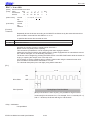
This parameter specifies whether to adorn red/black for ANK space characters in red printing mode (black/white inverted).
The ANK space characters are limited to ASCII code 20H in this setting.
In the character code table, if 7FHex is a space character, 7FHex is a target for this setting.
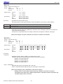
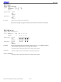
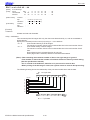
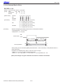
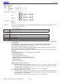
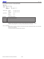
The following is an example of each setting.
It is possible to avoid unnecessary adornment in printing patterns that provide spacing of printing positions with ANK
space characters (20H) when red is specified.
(Print Example)
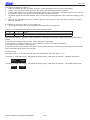
Print Data: <ESC> “4” “TOTAL” 20H 20H 20H 20H 20H 20H 20H 20H 20H “$1234” <LF>
<Condition 1> ANK adornment = “black/white inverted printing,” ANK space characters = “red/black adornment”
TOTAL
$1234
<Condition 2> ANK adornment = “black/white inverted printing,” ANK space characters = “no red/black adornment”
TOTAL
$1234
STAR LIne Mode Command Specifications
3-22
Rev. 0.00
SI
[Name]
[Code]
Select upside-down printing
ASCII
SI
Hexadecimal 0F
Decimal
15
[Defined Area]
[Initial Value]
[Function]
Thermal
Slip
Validation
Thermal
Slip
Validation
:
:
:
:
:
:
Upside-down printing cancelled
Upside-down printing cancelled
Upside-down printing cancelled
Specifies upside-down printing
This command is enabled only when at the top of the line.
Upside down and right-side up characters cannot both exist in the same line.
This command is enabled for following.
• ANK characters
• Kanji characters
• Bit images
• Logos
• Bar codes
<Slip>, <Validation>
When page mode is selected, only setting is valid
Setting is valid after switching to line mode.
(Note)The settings by this command are valid for all stations.
DC2
[Name]
[Code]
Cancel upside-down printing
ASCII
DC2
Hexadecimal
12
Decimal
18
[Defined Area]
[Initial Value]
[Function]
Thermal
Slip
Validation
Thermal
Slip
Validation
:
:
:
:
:
:
Upside-down printing cancelled
Upside-down printing cancelled
Upside-down printing cancelled
Cancels upside-down printing
This command is enabled only when at the top of the line.
(Note)The settings by this command are valid for all stations.
STAR Line Mode Command Specifications
3-23
Rev. 0.00
ESC RS i n
[Name]
[Code]
Specify/cancel character rotated mode
ASCII
ESC
RS
i
n
Hexadecimal
1B
1E
69
n
Decimal
27
30 105
n
[Defined Area]
[Initial Value]
[Function]
<Thermal>
Thermal
Slip
Validation
Thermal
Slip
Validation
:
:
:
:
:
:
0 ≤ n ≤ 2, 48 ≤ n ≤ 50, (“0” ≤ n ≤ “2”)
0 ≤ n ≤ 2, 48 ≤ n ≤ 50, (“0” ≤ n ≤ “2”)
Character rotation cancelled (n = 0)
Character rotation cancelled (n = 0)
Only setting is valid
Setting is valid after switching to slip or validation.
<Slip>, <Validation>
Specifies direction to rotate print (clockwise) or to cancel rotation for subsequent data, according to
the n value.
n
0, 48
1, 49
2, 50
Set rotation
Cancelled (0° rotation)
270° rotation
90° rotation
Rotated characters cannot be applied with underlines or upperlines.
The relationship between double-tall and double-wide is reverse to when cancelled when rotating.
When in Kanji character mode, rotation is effective for both ANK characters and Japanese characters.
Kanji character spacing is always applied with the two-byte Kanji character spacing value.
In standard specifications, rotation of IBM block is changed to vertical 8 dot fonts.
The following are precautions for 7 x 9 font character font specification.
• Characters are printed with 5 x 9 fonts (2P=1).
• Download characters registered with 5 x 9 fonts are printed.
• When rotation is cancelled, the characters return to 7 x 9 fonts. (When there is not 5 x 9 specification while rotation is specified.)
When page mode is selected, only setting is valid
Setting is valid after switching to line mode.
STAR LIne Mode Command Specifications
3-24
Rev. 0.00
3-3-4) Line Spacing
LF
[Name]
[Code]
Line feed
ASCII
Hexadecimal
Decimal
[Defined Area]
[Initial Value]
[Function]
Thermal
Slip
Validation
Thermal
Slip
Validation
[Name]
[Code]
:
:
:
:
:
:
Memory switch setting
1/6 inch line feed
1/6 inch line feed
Feeds the currently specified amount of paper.
If print data exists in the line buffer, it prints that data.
<Thermal>
CR
LF
0A
10
Initial value of line feed amount is set by the memory switch.
Carriage return (Print line feed)
ASCII
CR
Hexadecimal
0D
Decimal
13
[Defined Area]
[Initial Value]
[Function]
Thermal
Slip
Validation
Thermal
Slip
Validation
:
:
:
:
:
:
Memory switch setting
Memory switch setting
Memory switch setting
Specifies the function according to the memory switch value.
See each printer’s product specifications manual for details on the memory switch settings.
<Thermal>
Memory SW
Condition (1)
Condition (2)
Function
Ignored
Same as the LF code.
<Slip>, <Validation>
Memory SW
Condition (1)
Condition (2)
Condition (3)
Function
Ignored
Same as the LF code.
Executes only printing, with no paper feed.
STAR Line Mode Command Specifications
3-25
Rev. 0.00
ESC a n
[Name]
[Code]
Feed paper n lines
ASCII
ESC
Hexadecimal
1B
Decimal
27
[Defined Area]
[Initial Value]
[Function]
Thermal
Slip
Validation
Thermal
Slip
Validation
a
61
97
:
:
:
:
:
:
n
n
n
1 ≤ n ≤ 127
1 ≤ n ≤ 127
1 ≤ n ≤ 127
Memory switch setting
1/6 inch
1/6 inch
Executes paper feed of (currently specified line feed amount x n).
If print data exists in the line buffer, it prints that data.
This paper feed amount is unaffected even if there are vertical expanded characters in one line.
STAR LIne Mode Command Specifications
3-26
Rev. 0.00
ESC z n
[Name]
[Code]
Select line feed amount
ASCII
ESC
z
Hexadecimal
1B
7A
Decimal
27
122
[Defined Area]
[Initial Value]
[Function]
<Thermal>
n
1, 49
Thermal
Slip
Validation
Thermal
Slip
Validation
:
:
:
:
:
:
n
n
n
n = 1, 49
n = 0, 1, n = 48, 49
n = 0, 1, n = 48, 49
Memory switch setting
1/6 inch
1/6 inch
Specifies the line feed amount.
Amount of Line Feed
Specifies 4 mm line feed amount
<Slip>, <Validation>
n
0, 48
1, 49
Specifies the line feed amount.
Amount of Line Feed
Specifies 1/12 inch line feed amount
Specifies 1/6 inch line feed amount
Line feed amounts can be set independently for both line mode and page mode.
ESC 0
[Name]
(Thermal) Specify 3 mm line feed amount/(Slip) specify 1/8 line feed amount
[Code]
ASCII
Hexadecimal
Decimal
[Defined Area]
[Initial Value]
[Function]
<Thermal> ESC
1B
27
Thermal
Slip
Validation
Thermal
Slip
Validation
0
30
48
:
:
:
:
:
:
Memory switch setting
1/6 inch
1/6 inch
Specifies the line feed amount to 3 mm.
<Slip>, <Validation>
Specifies the line feed amount to 1/8 inch.
Line feed amounts can be set independently for both line mode and page mode.
STAR Line Mode Command Specifications
3-27
Rev. 0.00
ESC 1
[Name]
[Code]
(Thermal) Specify 3 mm line feed amount/(Slip) specify 7/72 inch line feed amount
ASCII
ESC
1
Hexadecimal
1B 31
Decimal
27 49
[Defined Area]
[Initial Value]
[Function]
<Thermal>
Thermal
Slip
Validation
Thermal
Slip
Validation
:
:
:
:
:
:
Memory switch setting
1/6 inch
1/6 inch
Specifies the line feed amount to 3 mm.
<Slip>, <Validation>
Specifies the line feed amount to 7/72 in.
Line feed amounts can be set independently for both line mode and page mode.
ESC J n
[Name]
[Code]
(Thermal) n/4 mm line feed/(Slip) execute n/72 line feed one time
ASCII
ESC
J
n
Hexadecimal
1B 4A
n
Decimal
27 74
n
[Defined Area]
[Initial Value]
Thermal
Slip
Validation
Thermal
Slip
Validation
:
:
:
:
:
:
1 ≤ n ≤ 255
1 ≤ n ≤ 255
1 ≤ n ≤ 255
-
[Function]
Execute paper feed.
If print data exists in the line buffer, it prints that data.
This paper feed amount is unaffected even if there are vertical expanded characters in one line.
The single line feed amount setting value is not changed by this command.
<Thermal> Executes a n/4mm paper feed.
Using this command will intermittently feed paper, therefore, it is normally recommended that this
command not be used.
(Currently set line feed amount –n/4 mm) portion is not printed.
<Slip>, <Validation>
Executes a n/72 in paper feed.
STAR LIne Mode Command Specifications
3-28
Rev. 0.00
ESC j n
[Name]
[Code]
Reverse paper feed
ASCII
ESC
Hexadecimal
1B
Decimal
27
[Defined Area]
[Initial Value]
[Function]
<Thermal>
Thermal
Slip
Validation
Thermal
Slip
Validation
j
6A
106
:
:
:
:
:
:
n
n
n
0 ≤ n ≤ 255
0 ≤ n ≤ 255
-
Three bytes ignored
<Slip>, <Validation>
Executes a n/72 in reverse direction paper feed.
If print data exists in the line buffer, it prints that data.
This paper feed amount is unaffected even if there are vertical expanded characters in one line.
The single line feed amount setting value is not changed by this command.
ESC I n
[Name]
[Code]
Executes (thermal) n/8 mm line feed/(slip) n/144 line feed one time.
ASCII
ESC
I
n
Hexadecimal
1B 49
n
Decimal
27 73
n
[Defined Area]
[Initial Value]
[Function]
<Thermal>
Thermal
Slip
Validation
Thermal
Slip
Validation
:
:
:
:
:
:
1 ≤ n ≤ 255
1 ≤ n ≤ 255
1 ≤ n ≤ 255
-
Executes paper feed.
If print data exists in the line buffer, it prints that data.
This paper feed amount is unaffected even if there are vertical expanded characters in one line.
The single line feed amount setting value is not changed by this command.
Executes a n/8 mm paper feed.
Using this command will intermittently feed paper, therefore, it is normally recommended that this
command not be used.
(Currently set line feed amount –n/8mm) portion is not printed.
<Slip>, <Validation>
Executes a n/144 in paper feed.
STAR Line Mode Command Specifications
3-29
Rev. 0.00
ESC A n
[Name]
[Code]
Defines (thermal) a 3 mm/4 mm line feed amount/Defines (slip) n/72 inch pitch line feed
ASCII
ESC
A
n
Hexadecimal
1B 41
n
Decimal
27 65
n
[Defined Area]
[Initial Value]
[Function]
Thermal
Slip
Validation
Thermal
Slip
Validation
:
:
:
:
:
:
0 ≤ n ≤ 255
0 ≤ n ≤ 85
0 ≤ n ≤ 85
-
Defines the line feed amount.
The line feed amount defined using this command is specified to the current line feed amount by the
ESC 2 command.
<Thermal>
n
0≤n≤9
10 ≤ n
Amount of Line Feed
Defines a 3 mm line feed amount
Defines a 4 mm line feed amount
<Slip>, <Validation>
Defines line feed amount for one line as n/72 inch.
Line feed amounts can be set independently for both line mode and page mode.
ESC 2
[Name]
[Code]
Specify line feed amount (ESC A n)
ASCII
ESC
2
Hexadecimal
1B 32
Decimal
27 50
[Defined Area]
[Initial Value]
[Function]
Thermal
Slip
Validation
Thermal
Slip
Validation
:
:
:
:
:
:
Memory switch setting
1/6 inch line feed
1/6 inch line feed
Specifies the line feed amount to the value defined by ESC A n.
STAR LIne Mode Command Specifications
3-30
Rev. 0.00
ESC 3 n
[Name]
[Code]
Specify n/216 inch paper feed
ASCII
ESC
3
n
Hexadecimal
1B 33
n
Decimal
27 51
n
[Defined Area]
[Initial Value]
[Function]
<Thermal>
Thermal
Slip
Validation
Thermal
Slip
Validation
:
:
:
:
:
:
0 ≤ n ≤ 255
0 ≤ n ≤ 255
1/6 inch line feed
1/6 inch line feed
Three bytes ignored
<Slip>, <Validation>
Sets subsequent line feed amounts to a value approximate to n/216 inch.
Because the minimum pitch for the paper feed mechanism is 1/144 of an inch, the setting value will
be approximated according to the following equation.
INT (n x 2/3 + 0.5)/144 of an inch
Line feed amounts can be set independently for both line mode and page mode.
ESC y n
[Name]
[Code]
Specify n/144 inch paper feed
ASCII
ESC
y
Hexadecimal
1B
79
Decimal
27
121
[Defined Area]
[Initial Value]
[Function]
<Thermal>
Thermal
Slip
Validation
Thermal
Slip
Validation
:
:
:
:
:
:
n
n
n
0 ≤ n ≤ 255
0 ≤ n ≤ 255
1/6 inch line feed
1/6 inch line feed
Three bytes ignored
<Slip>, <Validation>
Sets subsequent line feed amounts to a n/144 inch.
Line feed amounts can be set independently for both line mode and page mode.
STAR Line Mode Command Specifications
3-31
Rev. 0.00
3-3-5) Page Control Commands
FF
[Name]
[Code]
Form feed
ASCII
Hexadecimal
Decimal
[Defined Area]
[Initial Value]
[Function]
<Thermal>
FF
0C
12
Thermal
Slip
Validation
Thermal
Slip
Validation
:
:
:
:
:
:
-
Executes a form feed.
If the current position is at the top of the page, it form feeds to the top of the next page.
If there is data existing in the line buffer when executing a form feed, it prints that data, then executes the form feed.
However, by printing data remaining in the buffer, and moving to the top of the next page, a form
feed is considered to have been executed, so form feed is not performed.
<Slip>, <Validation>
Refer to the “Page Mode Command Details.”
STAR LIne Mode Command Specifications
3-32
Rev. 0.00
ESC C n
[Name]
[Code]
Set page length to n lines
ASCII
ESC
C
Hexadecimal
1B 43
Decimal
27 67
[Defined Area]
[Initial Value]
[Function]
<Thermal>
Thermal
Slip
Validation
Thermal
Slip
Validation
:
:
:
:
:
:
n
n
n
1 ≤ n ≤ 127
(Form feed amount initial value x 42)
-
The position whereat this command is processed is considered the top of the page and sets the
page length to (current form feed amount x n).
This command cancels the bottom margin setting when setting page length.
The page length set using this command is unaffected by changing the form feed amount later.
Moving to the top of the page is performed using the following commands.
• Form feed command (FF): Execute form feed
• Cutter command (ESC d n): Sets cutter position at top of page.
• Raster command (ESC * r B):Top of page when raster mode ends.
• Error cancel operations:
Sets error cancel operation end position at the top of the page.
<Slip>, <Validation>
Only setting is valid
Setting is valid after switching to thermal.
STAR Line Mode Command Specifications
3-33
Rev. 0.00
ESC C 0 n
[Name]
[Code]
Set n x 24 mm page length
ASCII
ESC
C
0
Hexadecimal
1B 43 00
Decimal
27 67
0
[Defined Area]
[Initial Value]
[Function]
<Thermal>
Thermal
Slip
Validation
Thermal
Slip
Validation
:
:
:
:
:
:
n
n
n
1 ≤ n ≤ 22
(Form feed amount initial value x 42)
-
The position whereat this command is processed is considered the top of the page and sets the
page length to (n x 24 mm).
This command cancels the bottom margin setting when setting page length.
The page length set using this command is unaffected by changing the form feed amount later.
Moving to the top of the page is performed using the following commands.
• Form feed command (FF): Execute form feed
• Cutter command (ESC d n): Sets cutter position at top of page.
• Raster command (ESC * r B):Top of page when raster mode ends.
• Error cancel operations:
Sets error cancel operation end position at the top of the page.
<Slip>, <Validation>
Only setting is valid
Setting is valid after switching to thermal.
STAR LIne Mode Command Specifications
3-34
Rev. 0.00
VT
[Name]
[Code]
Feed paper to vertical tab position
ASCII
VT
Hexadecimal 0B
Decimal
11
[Defined Area]
[Initial Value]
[Function]
<Thermal>
Thermal
Slip
Validation
Thermal
Slip
Validation
:
:
:
:
:
:
-
Feeds paper to the next vertical tab position.
This command is ignored if there are no tabs set.
If a vertical tab is set, and the current position is the same as the vertical tab position, or if it is below
that position, it feeds paper to the top of the next page.
If data exists in the line buffer when feeing paper to the vertical tab position, it executes the paper
feed to the vertical tab position after printing that data.
However, if moved to the vertical tab position by printing data remaining in the buffer, the move to
the vertical tab position is considered to have been executed, so a move to the next vertical tab position is not performed.
There is no initial value for the vertical tab.
<Slip>, <Validation>
One byte ignored
STAR Line Mode Command Specifications
3-35
Rev. 0.00
ESC B n1 n2 … nk NUL
[Name]
[Code]
Set vertical tab position
ASCII
ESC
B
Hexadecimal
1B 42
Decimal
27 66
[Defined Area]
[Initial Value]
[Function]
<Thermal>
Thermal
Slip
Validation
Thermal
Slip
Validation
:
:
:
:
:
:
n1
n1
n1
n2
n2
n2
..
..
..
nk
nk
nk
NUL
00
0
1 ≤ n ≤ 255, 0 ≤ n ≤ 16
-
Sets the vertical tab to the (current form feed amount x n) position.
All other vertical tabs set before setting the vertical tab using this command are cancelled.
A maximum of 16 vertical tabs can be set. However, the tab position must satisfy the condition of 1 ≤
n1 ≤ n2 ... ≤ nk.
When receiving such an illegal code, tabs up to the illegal code are set, but those after the illegal
code are discarded up to the NUL code so illegal code tab are not set.
The vertical tab set using this command is unaffected by changing the form feed amount later.
Vertical tabs set using the ESC B NUL command are cleared.
There is no initial value for the vertical tab.
<Slip>, <Validation>
Only setting is valid
Setting is valid after switching to thermal.
ESC B NUL
[Name]
[Code]
Clear vertical tab position
ASCII
ESC
B
Hexadecimal
1B 42
Decimal
27 66
[Defined Area]
[Initial Value]
[Function]
<Thermal>
Thermal
Slip
Validation
Thermal
Slip
Validation
:
:
:
:
:
:
NUL
00
0
-
Clears the currently set vertical tab.
<Slip>, <Validation>
Only setting is valid
Setting is valid after switching to thermal.
STAR LIne Mode Command Specifications
3-36
Rev. 0.00
3-3-6) Horizontal Direction Printing Position
ESC l n
[Name]
[Code]
Set left margin
ASCII
ESC
Hexadecimal
1B
Decimal
27
[Defined Area]
[Initial Value]
[Function]
<Thermal>
Thermal
Slip
Validation
Thermal
Slip
Validation
l
6C
108
:
:
:
:
:
:
n
n
n
0 ≤ n ≤ 255
0 ≤ n ≤ (right margin -2) ≤ 255
0 ≤ n ≤ (right margin -2) ≤ 255
n=0
n=0
n=0
Uses the left edge as a standard to set the left margin (current ANK character pitch x n).
Setting this command partway will take affect from the next line.
Character spacing is included in the character pitch but is unaffected by expansion settings.
The left margin set using this command is unaffected by changing the character pitch.
The right edge is also the reference for upside-down printing.
This command is ignored if settings are for a printing region less than 36 mm.
<Slip>, <Validation>
The left edge is also the reference for upside-down printing.
The left margin must be at least a minimum of 18 dots therebetween with the right margin. (*1)
If the printable region as set by the left and right margins is smaller than one character, including
the space between characters, printing is not possible. A question mark (?) is printed instead of the
character.
(*1) More than four characters of 7 x 9 fonts; more than three characters of 5 x 9 fonts (2P=1)
(when character spacing = 0)
When page mode is selected, only setting is valid
Setting is valid after switching to line mode.
㩷
㩷
㩷
㩷
㩷
㩷
㩷
㩷
Printable Region
Left
㩷 㩷 Margin
STAR Line Mode Command Specifications
Print Region
㩷Right Margin
3-37
Rev. 0.00
ESC Q n
[Name]
[Code]
Set right margin
ASCII
ESC
Hexadecimal
1B
Decimal
27
[Defined Area]
[Initial Value]
[Function]
<Thermal>
Thermal
Slip
Validation
Thermal
Slip
Validation
Q
51
81
:
:
:
:
:
:
n
n
n
0 ≤ n ≤ 255
2 ≤ n ≤ maximum printable digits ≤ 255
2 ≤ n ≤ maximum printable digits ≤ 255
Maximum printable digits
Maximum printable digits
Uses the left edge as a standard to set the print region as (current ANK character pitch x n).
Setting this command partway will take affect from the next line.
Character spacing is included in the character pitch but is unaffected by expansion settings.
The left margin set using this command is unaffected by changing the character pitch.
The right edge is also the reference for upside-down printing.
This command is ignored if settings are for a printing region less than 36 mm.
<Slip>, <Validation>
The left edge is also the reference for upside-down printing.
The print region within the defined range must be at least a minimum of 18 dots for the right margin.
If the printable region as set by the left and right margins is smaller than one character, including
the space between characters, printing is not possible. A question mark (?) is printed instead of the
character.
(*1) More than four characters of 7 x 9 fonts; more than three characters of 5 x 9 fonts (2P=1)
(when character spacing = 0)
When page mode is selected, only setting is valid
Setting is valid after switching to line mode.
㩷
㩷
㩷
㩷
㩷
㩷
㩷
㩷
Printable Region
Left Margin
Print Region
Right Margin
STAR LIne Mode Command Specifications
3-38
Rev. 0.00
HT
[Name]
[Code]
Move horizontal tab
ASCII
HT
Hexadecimal 09
Decimal
9
[Defined Area]
[Initial Value]
[Function]
Thermal
Slip
Validation
Thermal
Slip
Validation
:
:
:
:
:
:
-
Move print position to next horizontal tab position.
The current position moves to the next tab position when at the horizontal tab position.
This command is ignored with under the following conditions.
• When there is no horizontal tab set.
• When the current position is the same as the furthest right horizontal tab position or to the right of it.
There is no initial value for the horizontal tab.
In the underline/upperline modes, underlines and upperlines are not printed in the spaces created by
a horizontal tab.
ESC D n1 n2 … nk NUL
[Name]
[Code]
Set horizontal tab
ASCII
ESC
Hexadecimal
1B
Decimal
27
[Defined Area]
[Initial Value]
[Function]
Thermal
Slip
Validation
Thermal
Slip
Validation
D
44
68
:
:
:
:
:
:
n1
n1
n1
n2
n2
n2
..
..
..
nk
nk
nk
NUL
00
0
1 ≤ n ≤ 255, 0 ≤ n ≤ 32
1 ≤ n ≤ 255, 0 ≤ n ≤ 32
1 ≤ n ≤ 255, 0 ≤ n ≤ 32
-
Uses the left edge as a standard to set the horizontal tab to the position of (current ANK character
pitch x n).
The horizontal tab reference point is the right edge of the paper, regardless of the left margin.
ANK character pitches, including right spaces, are unaffected by expansion settings.
The right edge is also the reference for upside-down printing.
All other horizontal tabs set before setting the horizontal tab using this command are cancelled
A maximum of 32 horizontal tabs can be set.
However, the tab position must satisfy the following conditions.
If the following conditions are not met, data up to the NUL code is discarded.
Normal tabs that meet the conditions below are set and tabs after errors occur are not set.
• 1 < n1 < n2 … < nk
The horizontal tab set using this command is unaffected by changing the character pitch.
Horizontal tabs set using the ESC D NUL command are cleared.
There is no initial value for the horizontal tab.
(Note)The settings using this command are valid for all stations and modes.
STAR Line Mode Command Specifications
3-39
Rev. 0.00
ESC D NUL
[Name]
[Code]
Clear horizontal tab
ASCII
ESC
Hexadecimal
1B
Decimal
27
[Defined Area]
[Initial Value]
[Function]
Thermal
Slip
Validation
Thermal
Slip
Validation
D
44
68
:
:
:
:
:
:
NUL
00
0
-
Clears the currently set horizontal tab.
(Note)The settings using this command are valid for all stations and modes.
ESC GS A n1 n2
[Name]
[Code]
Move absolute position
ASCII
ESC
Hexadecimal
1B
Decimal
27
[Defined Area]
[Initial Value]
[Function]
<Thermal>
Thermal
Slip
Validation
Thermal
Slip
Validation
:
:
:
:
:
:
GS
1D
29
A
41
65
n1
n1
n1
n2
n2
n2
0 ≤ n1 ≤ 255, 0 ≤ n2 ≤ 255
0 ≤ n1 ≤ 255, 0 ≤ n2 ≤ 255
0 ≤ n1 ≤ 255, 0 ≤ n2 ≤ 255
-
Moves the printing position from the left margin to the (n1 + n2 x 256) dot position.
This command is ignored if the print region is exceeded.
The right margin is also the reference for upside-down printing.
The left margin is also the reference for upside-down printing.
<Slip>, <Validation>
The right margin is also the reference for upside-down printing.
STAR LIne Mode Command Specifications
3-40
Rev. 0.00
ESC GS R n1 n2
[Name]
[Code]
Move relative position
ASCII
ESC
GS
Hexadecimal
1B
1D
Decimal
27
29
[Defined Area]
[Initial Value]
[Function]
<Thermal>
Thermal
Slip
Validation
Thermal
Slip
Validation
:
:
:
:
:
:
R
52
82
n1
n1
n1
n2
n2
n2
0 ≤ n1 ≤ 255, 0 ≤ n2 ≤ 255
0 ≤ n1 ≤ 255, 0 ≤ n2 ≤ 255
0 ≤ n1 ≤ 255, 0 ≤ n2 ≤ 255
-
Moves the printing position from the current position to the (n1 + n2 x 256) dot position.
This command is ignored if the print region is exceeded.
When (n1 + n2 x 256) ≥ 32768, it moves {65536 – (n1 + n2 x 256)} dots in the left direction.
When (n1 + n2 x 256) < 32768, it moves (n1 + n2 x 256)} dots in the right direction.
The right margin is also the reference for upside-down printing.
The left margin is also the reference for upside-down printing.
<Slip>, <Validation>
The right margin is also the reference for upside-down printing.
STAR Line Mode Command Specifications
3-41
Rev. 0.00
ESC GS a n
[Name]
[Code]
Specify position alignment
ASCII
ESC GS
Hexadecimal
1B
1D
Decimal
27
29
[Defined Area]
[Initial Value]
[Function]
n
0, 48
1, 49
2, 50
Thermal
Slip
Validation
Thermal
Slip
Validation
:
:
:
:
:
:
a
61
97
n
n
n
0 ≤ n ≤ 2, 48 ≤ n ≤ 50, (“0” ≤ n ≤ “2”)
0 ≤ n ≤ 2, 48 ≤ n ≤ 50, (“0” ≤ n ≤ “2”)
0 ≤ n ≤ 2, 48 ≤ n ≤ 50, (“0” ≤ n ≤ “2”)
n=0
n=0
n=0
This specifies position alignment for all print data in one line, in the set print region.
Position alignment
Left alignment
Center alignment
Right alignment
<Slip>, <Validation>
When page mode is selected, only setting is valid
Setting is valid after switching to line mode.
(Note)The settings by this command are valid for all stations.
ABC
ABCD
ABCDE
<ESC><GS> “a” 1
<ESC><GS>” a” 0
ABC
ABCD
ABCDE
<ESC><GS>“ a” 2
STAR LIne Mode Command Specifications
3-42
ABC
ABCD
ABCDE
Rev. 0.00
3-3-7) Download
ESC & c1 c2 n d1 . . . d48
[Name]
[Code]
Register 12 x 24 dot font download characters
ASCII
ESC
& c1 c2
n d1
Hexadecimal
1B 26 c1 c2
n d1
Decimal
27 38 c1 c2
n d1
[Defined Area]
Thermal
Slip
Validation
Thermal
Slip
Validation
[Initial Value]
[Function]
<Thermal>
:
:
:
:
:
:
..
..
..
d48
d48
d48
c1 = 1, 49, c2 = 1, 49, 32 ≤ n ≤ 127, 0 ≤ d ≤ 255
-
Registers 12 x 24 dot font download characters to the nth address.
Download characters can be registered to <20>H to <7F>H. (96 characters can be registered for
each font.)
Those already registered to these addresses are overwritten.
When parameters c1 and c2 and n are outside of the defined area, subsequent data is handled as
normal data.
Horizontal
12 dot
Vertical
24 dot
d1
d3
d5
d7
d9
d11
d13
d15
d17
d19
d21
d23
d25
d27
d29
d31
d33
d35
d37
d39
d41
d43
d45
d47
●
●
●
●
●
●
●
●
●
●
●
●
●
●
●
●
●
●
●
●
●
●
●
●
●
●
●
●
●
●
●
●
●
●
●
●
●
●
●
●
●
●
●
●
●
●
●
●
●
●
●
●
●
●
●
●
●
●
●
●
●
●
●
●
●
●
●
●
●
●
●
●
●
●
●
●
●
●
●
●
●
●
●
●
●
●
●
●
●
●
●
●
●
●
●
●
●
●
●
●
●
●
●
●
●
●
●
●
●
●
●
●
●
●
●
●
●
●
●
●
●
●
●
●
●
●
●
●
●
●
●
●
●
●
●
●
●
●
●
●
●
●
●
●
●
●
●
●
●
●
●
●
●
●
●
●
●
●
●
●
●
●
●
●
●
●
●
●
●
●
●
●
●
●
●
●
●
●
●
●
●
●
●
●
●
●
●
●
●
●
●
●
bit7 bit6 bit5 bit4 bit3 bit2 bit1 bit0
d2
d4
d6
d8
d10
d12
d14
d16
d18
d20
d22
d24
d26
d28
d30
d32
d34
d36
d38
d40
d42
d44
d46
d48
●
●
●
●
○
○
○
○
●
●
●
●
○
○
○
○
●
●
●
●
○
○
○
○
●
●
●
●
○
○
○
○
●
●
●
●
○
○
○
○
●
●
●
●
○
○
○
○
●
●
●
●
○
○
○
○
●
●
●
●
○
○
○
○
●
●
●
●
○
○
○
○
●
●
●
●
○
○
○
○
●
●
●
●
○
○
○
○
●
●
●
●
○
○
○
○
●
●
●
●
○
○
○
○
●
●
●
●
○
○
○
○
●
●
●
●
○
○
○
○
●
●
●
●
○
○
○
○
●
●
●
●
○
○
○
○
●
●
●
●
○
○
○
○
●
●
●
●
○
○
○
○
●
●
●
●
○
○
○
○
●
●
●
●
○
○
○
○
●
●
●
●
○
○
○
○
●
●
●
●
○
○
○
○
●
●
●
●
○
○
○
○
bit7 bit6 bit5 bit4 bit3 bit2 bit1 bit0
● : Font data
○ : Invalid data
<Slip>, <Validation>
Only registration is possible.
Registration data is printable after switching to thermal.
STAR Line Mode Command Specifications
3-43
Rev. 0.00
ESC & c1 c2 n
[Name]
[Code]
Delete 12 x 24 dot font download characters
ASCII
ESC
& c1 c2
n
Hexadecimal
1B 26 c1 c2
n
Decimal
27 38 c1 c2
n
[Defined Area]
[Initial Value]
[Function]
<Thermal>
Thermal
Slip
Validation
Thermal
Slip
Validation
:
:
:
:
:
:
c1 = 1, 49, c2 = 0, 48, 32 ≤ n ≤ 127
-
Deletes 12 x 24 dot font download characters registered to the nth address.
<Slip>, <Validation>
Deleting is possible.
STAR LIne Mode Command Specifications
3-44
Rev. 0.00
ESC & NUL n1 n2 [m d1 d2 d3 d4 d5 (d6 d7)] n2 - n1 + 1
[Name]
[Code]
Register download characters
ASCII
ESC
& NUL
Hexadecimal
1B 26
00
Decimal
27 38
0
[Defined Area]
[Initial Value]
[Function]
<Thermal>
Thermal
Slip
Validation
Thermal
Slip
Validation
:
:
:
:
:
:
n1
n1
n1
n2
n2
n2
[m d1 d2 d3 d4 d5 (d6 d7)] n2 - n1 + 1
[m d1 d2 d3 d4 d5 (d6 d7)] n2 - n1 + 1
[m d1 d2 d3 d4 d5 (d6 d7)] n2 - n1 + 1
33 ≤ n1 ≤ n2 ≤ 127 (21h ≤ n1 ≤ n2 ≤ 7Fh), m = 0, 128 (00h, 80h), 0 ≤ d1 to d7 ≤ 255
33 ≤ n1 ≤ n2 ≤ 127 (21h ≤ n1 ≤ n2 ≤ 7Fh), m = 0, 128 (00h, 80h), 0 ≤ d1 to d7 ≤ 255
-
Only registration is possible.
Registration data is printable after switching to slip or validation.
<Slip>, <Validation>
Registers download characters to the specified character code.
A maximum of 22 download characters can be registered for 7 x 9 and 5 x 9 fonts.
The range of the location to write download characters is specified by n1 and n2. (When there is one
character to register, n1 = n2.)
If one has been already registered to an address, it is overwritten.
This command registers download characters independent to each font.
m indicates the relationship of the character pattern and the print head (see figure below).
Definition data (d1 to d7) set the bits that correspond to the dots to print to “1,” and the bits that correspond to the dots that are not printed to “0.”
Even if ESC @ (command initialization) is executed, the registered download character is not
cleared.
Registered data is shared by slip and validation.
Relationship of character pattern data and print head.
Upper
1. When m = 0 (00h)
D8
Pin No
1
2
3
4
5
6
7
8
9
●
●
●
●
●
●
●
●
●
Lower
D7
D6
D5
D4
D3
D2
D7
D6
D5
D4
D3
D2
(Not Used)
Upper
2. When m = 128 (80h)
Pin No
1
2
3
4
5
6
7
8
9
●
●
●
●
●
●
●
●
●
D1
D8
Lower
D1
(Not Used)
(Note)• When registering 7 x 9 fonts, dots adjacent in the horizontal direction do not print.
•When character rotation is specified, 7 x 9 font registered characters cannot be
printed. 5 x 9 font characters are always printed.
STAR Line Mode Command Specifications
3-45
Rev. 0.00
[Ex.:] When selecting 7 x 9 fonts, and defining the character to 21H:
㩷
㩷
8 dot
㩷
㩷
㩷
㩷
7 dot 㩷
㩷
㩷
㩷
㩷
㩷
㩷
㩷
㩷
㩷
㩷
㩷
㩷
㩷
㩷
㩷
㩷
㩷
㩷
㩷
㩷
㩷
㩷
㩷
㩷
d1㩷
d2㩷
d3㩷
d4㩷
d5㩷
d6
d7㩷
㩷
㩷
㩷
㩷
㩷
㩷
㩷
㩷
㩷
㩷
㩷
㩷
㩷
㩷
㩷
㩷
㩷
㩷
㩷
㩷
㩷
㩷
㩷
㩷
㩷
㩷
㩷
㩷
㩷
㪤㪪㪙㩷
㩷
㩷
㩷
㩷
㩷
㩷
㪣㪪㪙㩷
ESC & NUL n1 n2 m d1 d2 d3 d4 d5 d6 d7
Code (Hexadecimal) 1B 26 00 21 21 80 3E 40 88 00 88 40 3E
(1 when printing corresponding bits, and 0 for no print))
[Ex.:] When selecting 5 x 9 fonts, and defining the character to 21H:
㩷
㩷
㩷
㩷
5 dot 㩷
㩷
㩷
8 dot
㩷
d1㩷
d2㩷
d3㩷
d4㩷
d5㩷
㩷
㩷
㩷
㩷
㩷
㩷
㩷
㩷
ESC & NUL n1 n2 m d1 d2 d3 d4 d5
Code (Hexadecimal) 1B 26 00 21 21 00 38 45 45 45 7E
(1 when printing corresponding bits, and 0 for no print))
STAR LIne Mode Command Specifications
3-46
MSB㩷
㩷
㩷
㩷
㩷
㩷
㩷
LSB㩷
Rev. 0.00
ESC % N
[Name]
[Code]
Specify/cancel ANK download characters
ASCII
ESC
%
n
Hexadecimal
1B 25
n
Decimal
27 37
n
[Defined Area]
[Initial Value]
[Function]
n
0, 48
1, 49
Thermal
Slip
Validation
Thermal
Slip
Validation
:
:
:
:
:
:
n = 0, 1, 48, 49
n = 0, 1, 48, 49
n = 0, 1, 48, 49
Cancel ANK download character
Cancel ANK download character
Cancel ANK download character
Specifies/cancels ANK download characters
Download characters
Cancel ANK download characters
Specify ANK download characters
<Print example of download characters>
1. Registration of ANK download character (ESC & c1 c2 n d1…d48)
2. Specify ANK download characters (ESC % n (n = 1))
3. Print ANK download characters
(Note)The settings using this command are valid for all stations and modes.
STAR Line Mode Command Specifications
3-47
Rev. 0.00
3-3-8) Bit Image Graphics
ESC K n1 n2 d1 … dk
[Name]
[Code]
Standard density bit image
ASCII
ESC
K
Hexadecimal
1B 4B
Decimal
27 75
[Defined Area]
Thermal
:
n1
n1
n1
n2
n2
n2
d1
d1
d1
..
..
..
dk
dk
dk
1 ≤ {(n1 + n2 x 256) x 3} ≤ printable region
k = (n1 + n2 x 256)
0 ≤ d ≤ 255
Slip
:
1 ≤ (n1 + n2 x 256) ≤ printable region (total dot count)
k = (n1 + n2 x 256)
0 ≤ d ≤ 255
Validation
:
1 ≤ (n1 + n2 x 256) ≤ printable region (total dot count)
k = (n1 + n2 x 256)
[Initial Value]
[Function]
<Thermal>
Thermal
Slip
Validation
:
:
:
0 ≤ d ≤ 255
-
Prints bit images using 3 dots wide and 3 dots high per 1 dot of input data.
The following shows the details of data processing with this command.
• When {(n1 + n2 x 256) x 3} exceeds the printable region, only the data in the printing region is
printed.
• When {(n1 + n2 x 256) x 3} exceeds the currently set printable region, only the data in the printing
region is printed.
At this time, all data for the print region is discarded.
• If the current position already exceeds the print region, this command discards all data.
b7
䊶
䊶
䊶
䊶
䊶
䊶
䊶
䊶
䊶
䊶
䊶
䊶
䊶
䊶
䊶
䊶
䊶
䊶
䊶
䊶
䊶
䊶
䊶
䊶
䊶
䊶
䊶
䊶
䊶
䊶
䊶
䊶
䊶
䊶
䊶
䊶
䊶
䊶
䊶
䊶
䊶
䊶
䊶
䊶
䊶
䊶
䊶
䊶
䊶
䊶
䊶
䊶
䊶
䊶
䊶
䊶
䊶
䊶
䊶
䊶
䊶
䊶
䊶
䊶
䊶
䊶
䊶
䊶
䊶
䊶
䊶
䊶
STAR LIne Mode Command Specifications
3-48
b6
b5
b4
b3
b2
b1
b0
Rev. 0.00
<Slip>, <Validation>
This command prints bit images with only the data count determined by n1.
The amount of data that can be printed in one line is limited to the total dot count. Data that exceeds
the total dot count or the right margin is ignored.
See each printer’s product specifications manual for details regarding the total dot count.
After printing the bit image, the printer automatically returns to the character mode.
The following drawing shows the relationship of the print head needle wires and the data.
Upper
Pin No
1
2
3
4
5
6
7
8
9
●
●
●
●
●
●
●
●
●
b8
b7
b6
(Not Used)
STAR Line Mode Command Specifications
3-49
b5
b4
b3
Lower
b2
b1
Rev. 0.00
ESC L n1 n2 d1 … dk
[Name]
[Code]
High density bit image
ASCII
ESC
L
Hexadecimal
1B 4C
Decimal
27 76
[Defined Area]
Thermal
:
n1
n1
n1
n2
n2
n2
d1
d1
d1
..
..
..
dk
dk
dk
1 ≤ {(n1 + n2 x 256) ≤ printable region
k = (n1 + n2 x 256)
Slip
:
0 ≤ d ≤ 255
1 ≤ (n1 + n2 x 256) ≤ printable region (total half-dot count)
k = (n1 + n2 x 256)
Validation
:
0 ≤ d ≤ 255
1 ≤ (n1 + n2 x 256) ≤ printable region (total half-dot count)
k = (n1 + n2 x 256)
[Initial Value]
[Function]
<Thermal>
Thermal
Slip
Validation
:
:
:
0 ≤ d ≤ 255
-
Prints bit images using 1 dots wide and 3 dots high per 1 dot of input data.
The following shows the details of data processing with this command.
• When (n1 + n2 x 256) exceeds the printable region, only data in the print region is printed.
• When (n1 + n2 x 256) exceeds the currently set printable region, only the data in the printing region is printed.
At this time, all data for the print region is discarded.
• If the current position already exceeds the print region, this command discards all data.
b7
b6
b5
b4
b3
b2
b1
b0
䊶
䊶
䊶
䊶
䊶
䊶
䊶
䊶
䊶
䊶
䊶
䊶
䊶
䊶
䊶
䊶
䊶
䊶
䊶
䊶
䊶
䊶
䊶
䊶
<Slip>, <Validation>
This command executes the bit image of a density doubled (half dot printing) for just the data count
determined by n1 and n2.
The amount of data that can be printed in one line is only the total half-dot count. Data that exceeds
the total half-dot count or the right margin is ignored.
See each printer’s product specifications manual for details regarding the total half-dot count.
The relationship of the print head needle wires and the data is the same as ESC K (standard density
bit image).
When printing double-density bit images, dots adjacent in the horizontal direction do not print.
After printing the bit image, the printer automatically returns to the character mode.
When page mode is selected, all data is received and discarded.
STAR LIne Mode Command Specifications
3-50
Rev. 0.00
ESC k n1 n2 d1 … dk
[Name]
[Code]
Fine bit image
ASCII
ESC
Hexadecimal
1B
Decimal
27
[Defined Area]
Thermal
k
6B
107
:
n1
n1
n1
n2
n2
n2
d1
d1
d1
..
..
..
dk
dk
dk
n2 = 0
1 ≤ {(n1 + n2 x 256) x 8} ≤ printable region
k = {(n1 + n2 x 256) x 24}
[Initial Value]
[Function]
<Thermal>
Slip
Validation
Thermal
Slip
Validation
:
:
:
:
:
0 ≤ d ≤ 255
-
Prints bit images using 1 dots wide and 1 dots high per 1 dot of input data.
The following shows the details of data processing with this command.
• When {(n1 + n2 x 256) x 8} exceeds the printable region, only the data in the printing region is
printed.
• When {(n1 + n2 x 256) x 8} exceeds the currently set printable region, only the data in the printing
region is printed.
At this time, all data for the print region is discarded.
• If the current position already exceeds the print region, this command discards all data.
x byte =(n1 + n2 x 256)
24 dot
d1
dX x 1 + 1
dX x 2 + 1
d2
dX x 1 + 2
dX x 2 + 2
dX
dX x 2
dX x 3
dX x 23 + 1
dX x 23 + 2
dX x 24
bit7
bit6
bit5
bit4
bit3
<Slip>, <Validation>
All data received and discarded.
STAR Line Mode Command Specifications
3-51
bit2
bit1 bit0
Rev. 0.00
ESC X n1 n2 d1 … dk
[Name]
[Code]
Fine density bit image (Wire-dot, 24 pin compatible)
ASCII
ESC
X n1 n2 d1
.. dk
Hexadecimal
1B 58 n1 n2 d1
.. dk
Decimal
27 88 n1 n2 d1
.. dk
[Defined Area]
Thermal
:
1 ≤ (n1 + n2 x 256) ≤ printable region
k = {(n1 + n2 x 256) x 3}
[Initial Value]
[Function]
<Thermal>
Slip
Validation
Thermal
Slip
Validation
:
:
:
:
:
0 ≤ d ≤ 255
-
Prints input bit images with 8 dots/mm resolution for both horizontal and vertical.
The following shows the details of data processing with this command.
• When {(n1 + n2 x 256) x 3} exceeds the printable region, only the data in the printing region is
printed.
• When {(n1 + n2 x 256) x 3} exceeds the currently set printable region, only the data in the printing
region is printed.
At this time, all data for the print region is discarded.
• If the current position already exceeds the print region, this command discards all data.
b7 b6 b5 b4 b3 b2 b1 b0
b7 b6 b5 b4 b3 b2 b1 b0
<Slip>, <Validation>
All data received and discarded.
STAR LIne Mode Command Specifications
3-52
b7 b6 b5 b4 b3 b2 b1 b0
Rev. 0.00
ESC ^ m n1 n2 d1 d2 … dk
[Name]
[Code]
9 Dot bit image
ASCII
Hexadecimal
Decimal
[Defined Area]
[Initial Value]
[Function]
<Thermal>
ESC
1B
27
Thermal
Slip
Validation
Thermal
Slip
Validation
^
5E
94
:
:
:
:
:
:
m
m
m
n1
n1
n1
n2
n2
n2
d1
d1
d1
d2
d2
d2
..
..
..
dk
dk
dk
0 ≤ m ≤ 1 (“0” ≤ m ≤ “1”)
0 ≤ m ≤ 1 (“0” ≤ m ≤ “1”)
-
All data received and discarded.
<Slip>, <Validation>
This command prints bit images with only the data count determined by n1, and n2 at standard or
double density.
Specify the horizontal print dot count (row) using n1 + n2 x 256 dots.
• m = 0:
Print standard density 9 dot bit images.
The maximum number of dots in the horizontal direction is the total number of dots.
• m = 1:
Print double density 9 dot bit images.
The maximum number of dots in the horizontal direction is the total number of half
dots.
Dots adjacent in the horizontal direction do not print.
When page mode is selected, all data is received and discarded.
(Note)• Data exceeding the maximum number of dots or the right margin is ignored.
• Total number of dots and total number of half-dots follows the memory switch setting.
(See the specifications manual)
• If m is outside of the definition, data after n1 is processed as normal data.
• When printing of the bit image is ended, the system returns to normal data processing.
The following drawing shows the relationship of the print head needle wires and the data.
Pin No
1
2
3
4
5
6
7
8
9
dn: 1 to 8 pin data
MSB
LSB
b7
b6
b5
b4
b3
b2
b1
b0
b7
b6
b5
b4
b3
b2
b1
b0
●
●
●
●
●
●
●
●
●
MSB
STAR Line Mode Command Specifications
dn dn
+ 1+: 1:
9 Pin
data
9 pin
data
3-53
LSB
Rev. 0.00
3-3-9) Logo
ESC FS q n [ x 11 x 1 2 y 11 y 1 2 d 1 … d k ] 1 … [ x n 1 x n 2 y n 1 y n 2 d 1 … d k ] n
[Name]
[Code]
Register logo
ASCII
Hexadecimal
Decimal
[Defined Area]
ESC
FS
q
n
[x11
x12
y11
y12
d1
..
dk]1
..
[xn1
xn2
yn1
yn2
d1
..
1B
1C
71
n
[x11
x12
y11
y12
d1
..
dk]1
..
[xn1
xn2
yn1
yn2
d1
..
dk]n
27
28
113
n
[x11
x12
y11
y12
d1
..
dk]1
..
[xn1
xn2
yn1
yn2
d1
..
dk]n
Thermal
:
1 ≤ n ≤ 255
0 ≤ xn1 ≤ 255, 0 ≤ xn2 ≤ 3 1
≤ (xn1 + xn2 x 256) ≤ 1023
0 ≤ yn1 ≤ 255, 0 ≤ yn2 ≤ 1
Slip
:
dk]n
1
≤ (yn1 + yn2 x 256) ≤ 288
0 ≤ d ≤ 255
k = {(xn1 + xn2 x 256) x (yn1 + yn2 x 256) x 8}
1 ≤ n ≤ 255
0 ≤ xn1 ≤ 255, 0 ≤ xn2 ≤ 3 1 ≤ (xn1 + xn2 x 256) ≤ 1023
≤ (yn1 + yn2 x 256) ≤ 288
0 ≤ yn1 ≤ 255, 0 ≤ yn2 ≤ 1 1
Validation
:
0 ≤ d ≤ 255
k = {(xn1 + xn2 x 256) x (yn1 + yn2 x 256) x 8}
1 ≤ n ≤ 255
0 ≤ xn1 ≤ 255, 0 ≤ xn2 ≤ 3 1 ≤ (xn1 + xn2 x 256) ≤ 1023
≤ (yn1 + yn2 x 256) ≤ 288
0 ≤ yn1 ≤ 255, 0 ≤ yn2 ≤ 1 1
0 ≤ d ≤ 255
[Initial Value]
[Function]
Thermal
Slip
Validation
:
:
:
k = {(xn1 + xn2 x 256) x (yn1 + yn2 x 256) x 8}
No registration
No registration
No registration
Register logo
Parameter details
• n:
Specifies registered logo count
• xn1, xn2:
Horizontal size of registered logo {(xn1 + xn2 x 256) x 8} dots
• yn1, yn2:
Vertical size of registered logo {(yn1 + yn2 x 256) x 8} dots
• d: Registered logo data
• k:
Logo data count
This command should be specified at the top of the line.
When the first parameter is determined to be free of error, the printer starts processing this command.
When logo register processing starts, all previously defined data is deleted.(It is not possible to reregister a portion of a plurality of defined logo data.)
Logo registration numbers are defined in rising order from 1.
If the defined area specified by the parameter is not empty, or if there is an error in the parameter
specification, register processing is aborted.(The pre-registered and complete data is effective.)
The printer should be reset if logo registration is completed or register processing is aborted.
If an error occurs while performing register processing (the time from when the first parameter is OK
until the printer initialization is completed after registering a logo), error processing, mechanical operation and status processing cannot be performed. Also, data must not be sent from the host during
that time.
This command is executed only for logo registration and does not accompany the printing operation.
Logos are printed using the ESC FS p (print NV logo) command.
The NV memory capacity is 4 Mbits (512 Kbytes 524,288 bytes).
However, 4 Kbytes (4,096 bytes) are kept as parameter information separate to the data so the data
region memory capacity is 520,192 Bytes.
Ex.: When the registered data size per each one is 6 Kbytes (6,144 bytes), it is possible to register
520,192/6144 = 84.
STAR LIne Mode Command Specifications
3-54
Rev. 0.00
(Note)Registration data shared by all stations, and modes.
If this command is used frequently, there is the possibility of damaging the non-volatile
memory. Write to the non-volatile memory less than 10 times in one day.
Relationship of logo and registered data
xn = xn1 + xn2 x 256, yn = yn1 + yn2 x 256
{ (xn 1 + xn2 x 256) x 8 } dot
Data
MSB
d(11)
d(21)
d(n1)
d(12)
d(22)
d(n2)
(yn1 + yn2 x 256) bite
(yn1 + yn2 x 256) x 8 dot
LSB
d(x1)
STAR Line Mode Command Specifications
d(x2)
d(xn)
3-55
Rev. 0.00
ESC FS p n m
[Name]
[Code]
Print logo
ASCII
Hexadecimal
Decimal
[Defined Area]
[Initial Value]
ESC
1B
27
FS
1C
28
p
70
112
n
n
n
m
m
m
Thermal
:
1 ≤ n ≤ 255
Slip
:
0 ≤ m ≤ 3, 48 ≤ m ≤ 51, (“0” ≤ m ≤ “3”)
1 ≤ n ≤ 255
Validation
:
0 ≤ m ≤ 3, 48 ≤ m ≤ 51, (“0” ≤ m ≤ “3”)
1 ≤ n ≤ 255
Thermal
Slip
Validation
:
:
:
0 ≤ m ≤ 3, 48 ≤ m ≤ 51, (“0” ≤ m ≤ “3”)
-
[Function]
Prints the logo of registration number n registered using the logo registration command ESC FS q
according to the print mode m.
n: Logo Specification
n
1 to 255
Function
Specified logo number
m: Print Mode
m
0, 48
1, 49
2, 50
3, 51
Logo Print Mode
Normal mode
Horizontal double size mode
Vertical double size mode
Double high/wide mode
• If the parameter is within the defined region, execute this command after printing the unprinted data
in the line buffer.
(Unprinted data is printed regardless of whether the specified logo was registered by n.) )
• It is not possible to print with other data in the same line (characters, bit images, bar codes).
• Form feed obeys the vertical print size of the logo.
• Print modes, excluding upside-down printing (enhanced, double, underline, character size, black/
white inverted, and 90˚ right rotation) are unaffected.
• If the logo horizontal print size exceeds the horizontal print region, the portion exceeding the area is
not printed.
• When page mode is selected, supports only vertical double high, and horizontal double wide
modes.
• Logos are printed according to the following command settings.
• Left margin (ESC I n)
• Right margin (ESC Q n)
• Position alignment (ESC GS a n)
• Absolute position movement (ESC GS A n1 n2)
• Relative position movement (ESC GS R n1 n2)
• Horizontal tab (HT)
• Upside-down printing (SI)
STAR LIne Mode Command Specifications
3-56
Rev. 0.00
ESC RS L m
[Name]
[Code]
Logo batch control
ASCII
ESC
Hexadecimal
1B
Decimal
27
[Defined Area]
Thermal
Slip
Validation
Thermal
Slip
Validation
[Initial Value]
[Function]
RS
1E
30
:
:
:
:
:
:
L
4C
76
m
m
m
0 ≤ m ≤ 3, 48 ≤ m ≤ 51, (“0” ≤ m ≤ “3”), m = 255
0 ≤ m ≤ 3, 48 ≤ m ≤ 51, (“0” ≤ m ≤ “3”), m = 255
0 ≤ m ≤ 3, 48 ≤ m ≤ 51, (“0” ≤ m ≤ “3”), m = 255
-
Controls logos specified by the parameter m.
After execution, resets the printer.
m: Print Mode
m
0, 48
1, 49
2, 50
3, 51
255
Logo Control Mode
Normal mode batch printing
Horizontal double size mode batch printing
Vertical double size mode batch printing
Double high/wide mode batch printing
Logo batch delete
• If the parameter is within the defined region, execute this command after printing the unprinted data
in the line buffer.
(Unprinted data is printed regardless of whether the specified logo was registered by n.) )
• Form feed obeys the vertical print size of the logo.
• Print modes, excluding upside-down printing (enhanced, double, underline, character size, black/
white inverted, and 90˚ right rotation) are unaffected by logos.
• Prints logo number as shown below in the line above each logo print.
This line is printed with ANK characters, so currently set adornment is applied.
(Print Ex.) “LOGO No. 1” (Each logo number is printed at the “1” position.)
• If the logo horizontal print size exceeds the horizontal print region, the portion exceeding the area is
not printed.
• This test print is affected by the following command settings.
• Left margin (ESC I n)
• Right margin (ESC Q n)
• Position alignment (ESC GS a n)
• Print region setting (ESC RS A n)
• Upside-down printing (SI)
• After batch printing output is ended, paper is fed automatically to the cutting position, paper is cut (if
the printer is equipped with a cutter), and the printer is reset.
<Slip>, <Validation>
When page mode is selected, four bytes ignored.
STAR Line Mode Command Specifications
3-57
Rev. 0.00
3-3-10) Bar Codes
ESC b n1 n2 n3 n4 d1 . . . dk RS
[Name]
[Code]
Print bar code
ASCII
ESC
Hexadecimal
1B
Decimal
27
[Defined Area]
Thermal
b
62
98
:
n1
n1
n1
n2
n2
n2
n3
n3
n3
n4
n4
n4
d1
d1
d1
..
..
..
dk
dk
dk
RS
1E
30
0 ≤ n1 ≤ 8, 48 ≤ n1 ≤ 56 (“0” ≤ n1 ≤ “8”)
1 ≤ n2 ≤ 4, 49 ≤ n2 ≤ 52 (“1” ≤ n2 ≤ “4”)
1 ≤ n4 ≤ 255
n3 (bar code mode), d (bar code data),
[Initial Value]
[Function]
<Thermal>
Slip
Validation
Thermal
Slip
Validation
:
:
:
:
:
Defined area of k (bar code data count) is different depending on the bar code type.
-
Bar code printing is executed according to the following parameters.
If n1, n2, n3 and n4 are acquired and detected to be out of the defined area, data up to RS is discarded.
• n1: Bar Code Type Selection
n1
0, 48
1, 49
2, 50
3, 51
4, 52
5, 53
6, 54
7, 55
8, 56
Bar Codes Types
UPC-E
UPC-A
JAN/EAN8
JAN/EAN13
Code39
ITF
Code128
Code93
NW-7
• n2: Character Selection Under Bar Code, and Line Feed Addition Selection
n2
1, 49
2, 50
3, 51
4, 52
Under-bar character selection and added line feed selection
No added under-bar charactersExecutes a form feed after bar code is printed.
Added under-bar charactersExecutes a form feed after bar code is printed.
No added under-bar charactersDoes not execute a form feed after bar code is printed.
Added under-bar charactersDoes not execute a form feed after bar code is printed.
STAR LIne Mode Command Specifications
3-58
Rev. 0.00
• n3: Bar Code Mode Selection
n3
1, 49
2, 50
3, 51
4, 52
5, 53
6, 54
7, 55
8, 56
9, 57
UPC-E, UPC-A, JAN/EAN8
JAN/EAN13, Code128, Code93
Minimum module 2 dots
Minimum module 3 dots
Minimum module 4 dots
-------------
Bar Codes Types
Code39, NW-7
Narrow : Wide = 2: 6 dots
Narrow : Wide = 3: 9 dots
Narrow : Wide = 4:12 dots
Narrow : Wide = 2: 5 dots
Narrow : Wide = 3: 8 dots
Narrow : Wide = 4:10 dots
Narrow : Wide = 2: 4 dots
Narrow : Wide = 3: 6 dots
Narrow : Wide = 4: 8 dots
ITF
Narrow : Wide = 2: 5 dots
Narrow : Wide = 4:10 dots
Narrow : Wide = 6:15 dots
Narrow : Wide = 2: 4 dots
Narrow : Wide = 4: 8 dots
Narrow : Wide = 6:12 dots
Narrow : Wide = 2: 6 dots
Narrow : Wide = 3: 9 dots
Narrow : Wide = 4:12 dots
• n4: Bar code height (dot count)
Spec. 1: When the height of the bar code is more than the form feed amount, the form feed amount
is automatically doubled.
Spec. 2: Line feed according to (bar code height + under-bar characters)
• k (bar code data count), d (bar code data)
Bar Codes Types
UPC-E
UPC-A
JAN/EAN8
JAN/EAN13
Code39
Defined area of k
11 ≤ k ≤ 12
11 ≤ k ≤ 12
7≤k≤8
12 ≤ k ≤ 13
1≤k
Defined area of d
48 ≤ d ≤ 57 (“0” ≤ d ≤ “9”)
48 ≤ d ≤ 57 (“0” ≤ d ≤ “9”)
48 ≤ d ≤ 57 (“0” ≤ d ≤ “9”)
48 ≤ d ≤ 57 (“0” ≤ d ≤ “9”)
48 ≤ d ≤ 57 (“0” ≤ d ≤ “9”), 65 ≤ d ≤ 90 (“A” ≤ d ≤ “Z”)
ITF
1≤k
32, 36, 37, 43, 45, 46, 47(SP, “$”, “%”, “+”, “-”, “.”, “/”)
48 ≤ d ≤ 57 (“0” ≤ d ≤ “9”)
For odd numbers
Code128
Code93
NW-7
0 data is automatically added
to the top.
1≤k
1≤k
1≤k
0 ≤ d ≤ 127
0 ≤ d ≤ 127
48 ≤ d ≤ 57 (“0” ≤ d ≤ “9”), 65 ≤ d ≤ 68 (“A” ≤ d ≤ “D”)
36, 43, 45, 46, 47, 58 (“$”, “+”, “-”, “.”, “/”, “:”)
97, 98, 99, 100 (“a,” “b,” “c,” “d”)
• UPC-E: k = 11 (or 12)
The 12th check digit is automatically applied, so it is ignored even if specified.
Command is ignored if the data cannot be shortened. Data conversion to rectangles is automatic.
• UPC-A: k = 11 (or 12)
The 12th check digit is automatically applied, so it is ignored even if specified.
• JAN/EAN -8: k = 7 (or 8)
The 8th check digit is automatically applied, so it is ignored even if specified.
• JAN/EAN -13: k = 12 (or 13)
The 13th check digit cannot be automatically applied, so it is ignored even if specified.
• CODE39: k is freely set, and maximum value differs according to the mode.
Start and stop codes (*) are automatically included.
• ITF: k is freely set, and maximum value differs according to the mode.
If the data is an odd line, 0 data is automatically appended to the top.
• CODE128: k is freely set, and maximum value differs according to the mode and print character
type.
Check character is automatically appended.
• CODE93: k is freely set, and maximum value differs according to the mode and print character
type.
The start/stop code (□) is automatically appended.
• NW7: k is freely set, and maximum value differs according to the mode and print character type.
Both start/stop codes are included in the data (but not automatically applied).
STAR Line Mode Command Specifications
3-59
Rev. 0.00
3-3-11) Cutter Control
ESC d n
[Name]
Auto-cutter:
[Code]
ASCII
Hexadecimal
Decimal
ESC
1B
27
d
64
100
n
n
n
[Defined Area]
Thermal
:
0 ≤ d ≤ 3,
[Initial Value]
Slip
Validation
Thermal
Slip
Validation
:
:
:
:
:
48 ≤ d ≤ 51 (“0” ≤ d ≤ “3”)
-
[Function]
<Thermal>
n
0, 48
Executes the auto-cutter.
After auto-cutter is executed, the printer considers that position to be the top of the page.
Auto-cutter
Full cut at the current position.
Print data in line buffer is printed before a full cut.
1, 49
Models not provided the auto-cutter execute only functions other than the cutting operation
(printing/paper feed operations).
Partial cut at the current position.
Print data in line buffer is printed before a partial cut.
2, 50
Models not provided the auto-cutter execute only functions other than the cutting operation
(printing/paper feed operations).
Paper is fed to cutting position, then a full cut.
Print data in line buffer is printed before the operation described above.
3, 51
Models not provided the auto-cutter execute only functions other than the cutting operation
(printing/paper feed operations).
Paper is fed to cutting position, then a partial cut.
Print data in line buffer is printed before the operation described above.
Models not provided the auto-cutter execute only functions other than the cutting operation
(printing/paper feed operations).
(*) The auto-cutter function operates in the following ways on models that only have a full cut or a
partial cut.
• Models that perform only a full cut.:
Executes a full cut when for instructions calling for a
partial cut.
• Models that perform only a partial cut.:
Executes a partial cut when for instructions calling
for a full cut.
<Slip>, <Validation>
Three bytes ignored
STAR LIne Mode Command Specifications
3-60
Rev. 0.00
3-3-12) External Device Drive
ESC BEL n1 n2
[Name]
[Code]
Set external drive device 1 pulse width
ASCII
ESC BEL n1 n2
Hexadecimal
1B
07 n1 n2
Decimal
27
7 n1 n2
[Defined Area]
[Initial Value]
Thermal
Slip
Validation
Thermal
:
:
:
:
1 ≤ n1 ≤ 127, 1 ≤ n2 ≤ 127
1 ≤ n1 ≤ 127, 1 ≤ n2 ≤ 127
1 ≤ n1 ≤ 127, 1 ≤ n2 ≤ 127
n1 = 20 (Energizing time: 200 msec)
Slip
:
n2 = 20 (Delay time: 200 msec)
n1 = 20 (Energizing time: 200 msec)
Validation
:
n2 = 20 (Delay time: 200 msec)
n1 = 20 (Energizing time: 200 msec)
n2 = 20 (Delay time: 200 msec)
[Function]
Sets the energizing and delay times for drive of the external device.
• Energizing time = 10 x n1 (ms)
• Delay time = 10 x n2 (ms)
ON
Drive Pulse
OFF
Print Operation
10 × n1(msec)
10 × n2(msec)
(Energizing Time)
(Delay Time)
Printing and Paper Feed Prohibited
After printing, this is executed by BEL (External device 1 drive instruction) or FS (External device 1
drive instruction).
Handled in the following way when n1 and n2 are out of range.
• When n1 = 0, or n2 = 0, this command is ignored.
• When n1 > 127 is specified, n1 = 127; when n2 > 127 is specified, n2 = 127.
(Note)The settings using this command are valid for all stations and modes.
STAR Line Mode Command Specifications
3-61
Rev. 0.00
BEL
[Name]
[Code]
External device 1 drive instruction
ASCII
BEL
Hexadecimal
07
Decimal
7
[Defined Area]
[Initial Value]
[Function]
Thermal
Slip
Validation
Thermal
Slip
Validation
:
:
:
:
:
:
-
Executes the external device drive conditions set according to the command to set the external drive
device pulse width (ESC BEL n1 n2).
As with other commands, it temporarily stores data in the data buffer, then executes in the order received.
(Note)External device 1 and external device 2 cannot be executed simultaneously.
FS
[Name]
[Code]
External device 1 drive instruction
ASCII
FS
Hexadecimal 1C
Decimal
28
[Defined Area]
[Initial Value]
[Function]
Thermal
Slip
Validation
Thermal
Slip
Validation
:
:
:
:
:
:
-
Executes the external device drive conditions set according to the command to set the external drive
device pulse width (ESC BEL n1 n2).
As with other commands, it temporarily stores data in the data buffer, then executes in the order received.
(Note)External device 1 and external device 2 cannot be executed simultaneously.
STAR LIne Mode Command Specifications
3-62
Rev. 0.00
SUB
[Name]
[Code]
External device 2 drive instruction
ASCII
SUB
Hexadecimal
1A
Decimal
26
[Defined Area]
[Initial Value]
[Function]
Thermal
Slip
Validation
Thermal
Slip
Validation
:
:
:
:
:
:
-
Drives external device 2. The energizing time and delay time for the external device 2 are fixed at
200 ms each.
As with other commands, it temporarily stores data in the data buffer, then executes in the order
received.
(Note)External device 1 and external device 2 cannot be executed simultaneously.
EM
[Name]
[Code]
External device 2 drive instruction
ASCII
EM
Hexadecimal
19
Decimal
25
[Defined Area]
[Initial Value]
[Function]
Thermal
Slip
Validation
Thermal
Slip
Validation
:
:
:
:
:
:
-
Drives external device 2.The energizing time and delay time for the external device 2 are fixed at
200 ms each.
As with other commands, it temporarily stores data in the data buffer, then executes in the order
received.
(Note)External device 1 and external device 2 cannot be executed simultaneously.
STAR Line Mode Command Specifications
3-63
Rev. 0.00
ESC GS BEL m t1 t2
[Name]
[Code]
Ring buzzer
ASCII
Hexadecimal
Decimal
[Defined Area]
[Initial Value]
[Function]
m
1, 49
2, 50
ESC
1B
27
GS
1D
29
BEL
07
7
m
m
m
t1
t1
t1
t2
t2
t2
Thermal
:
1 ≤ m ≤ 2, 49 ≤ m ≤ 50 (“1” ≤ m ≤ “2”)
Slip
:
1 ≤ t1 ≤ 255, 1 ≤ t2 ≤ 255
1 ≤ m ≤ 2, 49 ≤ m ≤ 50 (“1” ≤ m ≤ “2”)
Validation
:
1 ≤ t1 ≤ 255, 1 ≤ t2 ≤ 255
1 ≤ m ≤ 2, 49 ≤ m ≤ 50 (“1” ≤ m ≤ “2”)
Thermal
Slip
Validation
:
:
:
1 ≤ t1 ≤ 255, 1 ≤ t2 ≤ 255
-
Rings buzzer.
m specifies the buzzer drive terminal.
Buzzer Drive Terminals
Buzzer drive terminal 1
Buzzer drive terminal 2
t1 specifies the energizing time; t2 specifies the delay time.
• Energizing time = 20 msec x t1
• Delay time = 20 msec x t2
Buzzer cannot ring whle printer is printing.
This command is prohibited for use for anything other than ringing the buzzer.
(When this command is used for the drawer drive on models equipped with an external device
terminal, it will be damaged, so care is needed.) )
ON
Drive Pulse
OFF
20 × t1 (msec)
(Energizing Time
Print Operation
STAR LIne Mode Command Specifications
20 × t2 (msec)
(Delay Time)
Printing and Paper Feed Prohibited
3-64
Rev. 0.00
ESC GS EM DC1 m n1 n2
[Name]
[Code]
Set external buzzer drive pulse condition
ASCII
ESC
GS
EM DC1
Hexadecimal
1B
1D
19
11
Decimal
27
29
25
17
[Defined Area]
[Initial Value]
[Function]
m
1, 49
2, 50
m
m
m
n1
n1
n1
n2
n2
n2
Thermal
:
1 ≤ m ≤ 2, 49 ≤ m ≤ 50, (“1” ≤ m ≤ “2”)
Slip
:
0 ≤ n1 ≤ 255, 0 ≤ n2 ≤ 255
1 ≤ m ≤ 2, 49 ≤ m ≤ 50, (“1” ≤ m ≤ “2”)
Validation
:
0 ≤ n1 ≤ 255, 0 ≤ n2 ≤ 255
1 ≤ m ≤ 2, 49 ≤ m ≤ 50, (“1” ≤ m ≤ “2”)
Thermal
Slip
Validation
:
:
:
0 ≤ n1 ≤ 255, 0 ≤ n2 ≤ 255
n1 = 0, n2 = 0
n1 = 0, n2 = 0
n1 = 0, n2 = 0
Set external buzzer drive pulse condition.
m specifies the buzzer drive terminal that sets the condition.
Buzzer Drive Terminals
Buzzer drive terminal 1
Buzzer drive terminal 2
n1 specifies the energizing time; n2 specifies the delay time.
• Energizing time = 20 msec x n1
• Delay time = 20 msec x n2
ON
Drive Pulse
OFF
Print Operation
20 × n1(msec)
20 × n2(msec)
(Energizing Time)
(Delay Time)
Printing and Paper Feed Prohibited
The drive of the external buzzer set by this command is performed by ESC GS EM DC2 m n1 n2.
The set value is not initialized by ESC @, or CAN.
(Note)The settings using this command are valid for all stations and modes.
STAR Line Mode Command Specifications
3-65
Rev. 0.00
ESC GS EM DC2 m n1 n2
[Name]
[Code]
Execute external buzzer drive
ASCII
ESC
GS EM
Hexadecimal
1B
1D
19
Decimal
27
29
25
[Defined Area]
[Initial Value]
[Function]
DC2
12
18
m
m
m
n1
n1
n1
n2
n2
n2
Thermal
:
1 ≤ m ≤ 2, 49 ≤ m ≤ 50, (“1” ≤ m ≤ “2”)
Slip
:
1 ≤ n1 ≤ 20, n2 = 0
1 ≤ m ≤ 2, 49 ≤ m ≤ 50, (“1” ≤ m ≤ “2”)
Validation
:
1 ≤ n1 ≤ 20, n2 = 0
1 ≤ m ≤ 2, 49 ≤ m ≤ 50, (“1” ≤ m ≤ “2”)
Thermal
Slip
Validation
:
:
:
1 ≤ n1 ≤ 20, n2 = 0
-
Repeatedly drives the buzzer according to the ON/OFF conditions set by the external buzzer drive
pulse condition command ESC GS EM DC1 m t1 t2.
m specifies the buzzer drive terminal to drive.
m
1, 49
2, 50
Buzzer Drive Terminals
Buzzer drive terminal 1
Buzzer drive terminal 2
Specifies the number of times to repeat buzzer drive with (n2 x 256 + n1).
Buzzer cannot ring while printer is printing.
This command is prohibited for use for anything other than ringing the buzzer.
(When this command is used for the drawer drive on models equipped with an external device
terminal, it will be damaged, so it is absolutely prohibited.) )
The buzzer can be stopped by pressing the FEED switch or the RELEASE switch while the buzzer is
ringing, or opening the receipt cover or the slip cover.
[Ex.:]
n1 = 8
ON
Drive Pulse
OFF
ON OFF
Printing/Paper Feed Prohibited
Print Operation
(Note) If the off time is set to 0 (zero), it is possible to ring the buzzer
continuously for the amount of n1. For example, if on = 5 seconds, off = 0,
and n1 = 20 times, the buzzer will ring for 100 seconds.
STAR LIne Mode Command Specifications
3-66
Rev. 0.00
3-3-13) Print Settings
ESC RS d n
[Name]
[Code]
Set print density
ASCII
ESC
Hexadecimal
1B
Decimal
27
[Defined Area]
[Initial Value]
[Function]
<Thermal>
n
0, 48
1, 49
2, 50
3, 51
4, 52
5, 53
6, 54
7, 55
8, 56
9, 57
10, 65
11, 66
12, 67
13, 68
14, 69
15, 70
Thermal
Slip
Validation
Thermal
Slip
Validation
RS
1E
30
d
64
100
n
n
n
:
0 ≤ n ≤ 15
:
:
:
:
:
48 ≤ n ≤ 57 (”0” ≤ n ≤ “9”), 65 ≤ n ≤ 70 (”A” ≤ n ≤ “F”)
Memory switch setting
-
Sets print density.
This command stops printing to be executed.
Print Density
Print density 1.3
Print density 1.2
Print density 1.1
Print density 1.0
Print density 0.9
Print density 0.8
Print density 0.7
(Reserved)
(Reserved)
(Reserved)
(Reserved)
(Reserved)
(Reserved)
(Reserved)
(Reserved)
(Reserved)
<Slip>, <Validation>
Only setting is valid
Setting is valid after switching to thermal.
STAR Line Mode Command Specifications
3-67
Rev. 0.00
ESC RS r n
[Name]
[Code]
Set printing speed
ASCII
ESC
Hexadecimal
1B
Decimal
27
RS
1E
30
r
72
114
n
n
n
[Defined Area]
Thermal
:
0≤n≤2
[Initial Value]
Slip
Validation
Thermal
Slip
Validation
:
:
:
:
:
48 ≤ n ≤ 50 (“0” ≤ n ≤ “2”)
Memory switch setting
-
[Function]
<Thermal>
n
0, 48
1, 49
2, 50
Sets print speed.
This command stops printing to be executed.
Print Speed
High speed
Mid-speed
Slow speed
<Slip>, <Validation>
Only setting is valid
Setting is valid after switching to thermal.
STAR LIne Mode Command Specifications
3-68
Rev. 0.00
3-3-14) Status
ESC RS a n
[Name]
[Code]
Set status transmission conditions
ASCII
ESC
RS
a
Hexadecimal
1B
1E 61
Decimal
27
30 97
[Defined Area]
[Initial Value]
Thermal
Slip
Validation
Thermal
Slip
Validation
:
:
:
:
:
:
n
n
n
0 ≤ n ≤ 3, 48 ≤ n ≤ 51, (“0” ≤ n ≤ “51”)
0 ≤ n ≤ 3, 48 ≤ n ≤ 51, (“0” ≤ n ≤ “51”)
0 ≤ n ≤ 3, 48 ≤ n ≤ 51, (“0” ≤ n ≤ “51”)
DIPS switches/Memory switch setting
DIPS switches/Memory switch setting
DIPS switches/Memory switch setting
[Function]
Sets the status transmission conditions. See Appendix 2 for details regarding ASB status.
This command is effective only on printers that have an interface capable of bi-directional data
communications.
When using serial, parallel or USB (vendor class), use is possible.
The command is ignored (set to enable auto-status) when using Ethernet or wireless LAN.
Settings of this command are unaffected by the ESC @ (command initialization) command.
See each printer’s product specifications manual for details on the memory switch settings.
(Note)The settings using this command are valid for all stations and modes.
STAR Line Mode Command Specifications
3-69
Rev. 0.00
ESC ACK SOH
[Name]
[Code]
Real-time printer status (ASB Status)
ASCII
ESC ACK SOH
Hexadecimal
1B
06
01
Decimal
27
6
1
[Defined Area]
[Initial Value]
[Function]
Thermal
Slip
Validation
Thermal
Slip
Validation
:
:
:
:
:
:
-
This command is effective only when using an interface capable of bi-directional data
communications.
When this command is received, the printer sends the status to the host in real time.
Immediately executed not when taking out from the reception buffer, but when received from the
host.)
Bi-directional parallel interfaces enter a “data present” state.
See the Appendix Auto Status for details regarding status.
When in the serial interface DTR mode, and using a parallel interface, set so that the status can be
inquired even when offline for errors, etc.
This command is not used when auto-status is valid.
When this command is sent once to the printer, do not send the next ESC ACK SOH command until
the final auto status has been received.
See Appendix 2 Automatic Status for details regarding ASB status.
ENQ
[Name]
[Code]
Real-time printer status (1)
ASCII
ENQ
Hexadecimal
05
Decimal
5
[Defined Area]
[Initial Value]
[Function]
Thermal
Slip
Validation
Thermal
Slip
Validation
:
:
:
:
:
:
-
This command is effective only when using an interface capable of bi-directional data
communications.
When this command is received, the printer sends one byte of ENQ status to the host in real time.
Immediately executed not when taking out from the reception buffer, but when received from the
host.)
Bi-directional parallel interfaces enter a “data present” state.
See Appendix ENQ Command Status for details regarding status.
When this command is sent once to the printer, do not send the next ENQ command until the ENQ
status has been received.
This command is not used when auto-status is valid.
See Appendix 2 ENQ Command Status for details regarding status.
STAR LIne Mode Command Specifications
3-70
Rev. 0.00
EOT
[Name]
[Code]
Real-time printer status (2)
ASCII
EOT
Hexadecimal
04
Decimal
4
[Defined Area]
[Initial Value]
[Function]
Thermal
Slip
Validation
Thermal
Slip
Validation
:
:
:
:
:
:
-
This command is effective only when using an interface capable of bi-directional data
communications.
When this command is received, the printer sends one byte of EOT status to the host in real time.
Immediately executed not when taking out from the reception buffer, but when received from the
host.)
Bi-directional parallel interfaces enter a “data present” state.
See Appendix EOT Command Status for details regarding status.
When this command is sent once to the printer, do not send the next EOT command until the EOT
status has been received.
This command is not used when auto-status is valid.
See Appendix 2 EOT Command Status for details regarding status.
ETB
[Name]
[Code]
Update of ETB status of ASB
ASCII
ETB
Hexadecimal
17
Decimal
23
[Defined Area]
[Initial Value]
[Function]
Thermal
Slip
Validation
Thermal
Slip
Validation
:
:
:
:
:
:
-
This command is effective only when using an interface capable of bi-directional data
communications.
This command waits until all printing is completed (the print motor is stopped), and after printing is
completed, the auto status printer status 1-1 (ETB command) becomes 1 (ETB execution completed), and the ETB counter is updated (incremented).
Note that when executing this command, and print data remains the line buffer, this command is executed after printing the remaining data.
The hose checks that this bit has changed to “1” thereby making it possible to ascertain that the
printing of the sent data is completed.
This ETB status bit is cleared to “0” when returned to host.
Also, ETB is appended to the end of 1 data block and several blocks are sent at once. By getting the
ETB counter sequentially, it is possible to confirm the end of printing the several blocks.
Note that the ETB counter is cleared to zero by the ESC RS E command.
The following shows the details of the processing in the printer with this command.
(1)
Reads out the ETB command from the reception buffer.
(2)
Waits for the printing of data to be completed before the ETB command
(3)
After checking the end of printing, the auto status ETB status is set, and the ETB counter is incremented.
(4)
Auto status transmission (only when auto status is valid)
See Appendix 2 for details regarding the ASB status.
STAR Line Mode Command Specifications
3-71
Rev. 0.00
ESC RS E n
[Name]
[Code]
Initialize ASB ETB counter, and ETB status.
ASCII
ESC
RS
E
n
Hexadecimal
1B
1E 45
n
Decimal
27
30 69
n
[Defined Area]
[Initial Value]
[Function]
Thermal
Slip
Validation
Thermal
Slip
Validation
:
:
:
:
:
:
n = 0, 48 (“0”)
n = 0, 48 (“0”)
n = 0, 48 (“0”)
ASB ETB counter = 0
ASB ETB counter = 0
ASB ETB counter = 0
Clears the ASB ETB counter to zero and clears the ETB status.
However, when clearing the ETB counter to zero using this command, ASB status is not transmitted.
The ETB counter and ETB status are initialized by the following command in addition to this command.
• Cancel print data and initialize commands <CAN>
STAR LIne Mode Command Specifications
3-72
Rev. 0.00
3-3-15) Kanji Characters
ESC p
[Name]
Specify JIS Kanji character mode
[Code]
ASCII
Hexadecimal
Decimal
[Defined Area]
[Initial Value]
[Function]
ESC
1B
27
Thermal
Slip
Validation
Thermal
Slip
Validation
p
70
112
:
:
:
:
:
:
Cancel JIS Kanji character mode
Cancel JIS Kanji character mode
Cancel JIS Kanji character mode
Specifies JIS Kanji character mode
When in JIS Kanji character mode, all character codes are handled as 2 byte Japanese characters
(First byte: upper code; second byte: lower code).
Even when setting the JIS Kanji mode, the control code is valid.
This command is ignored for models not equipped with Japanese and Kanji characters and when
the specification for the location of use is specified as SBCS (single byte countries) by the memory
switch.
<Slip>, <Validation>
When page mode is selected, only setting is valid
Setting is valid after switching to line mode.
(Note)The settings by this command are valid for all stations.
ESC q
[Name]
[Code]
Cancel JIS Kanji character mode
ASCII
ESC
q
Hexadecimal
1B
71
Decimal
27
113
[Defined Area]
[Initial Value]
[Function]
Thermal
Slip
Validation
Thermal
Slip
Validation
:
:
:
:
:
:
Cancel JIS Kanji character mode
Cancel JIS Kanji character mode
Cancel JIS Kanji character mode
Cancels JIS Kanji character mode.
This command is ignored for models not equipped with Japanese and Kanji characters and when
the specification for the location of use is specified as SBCS (single byte countries) by the memory
switch.
<Slip>, <Validation>
When page mode is selected, only setting is valid
Setting is valid after switching to line mode.
(Note)The settings by this command are valid for all stations.
STAR Line Mode Command Specifications
3-73
Rev. 0.00
ESC $ n
[Name]
[Code]
Specify/cancel JIS Kanji character mode
ASCII
ESC
$
n
Hexadecimal
1B 24
n
Decimal
27 36
n
[Defined Area]
[Initial Value]
[Function]
n
0, 48
1, 49
Thermal
Slip
Validation
Thermal
Slip
Validation
:
:
:
:
:
:
n = 0, 1, 48, 49
n = 0, 1, 48, 49
n = 0, 1, 48, 49
Memory switch setting
Memory switch setting
Memory switch setting
Specifies and cancels the shift JIS Kanji character mode.
Shift JIS Japanese Character Mode
Cancel shift JIS Kanji character mode
Specify shift JIS Kanji character mode
When in shift JIS Kanji character mode, if the data is <80>H to <9F>H or <E0>H to <FF>H, this is
handled as 2 byte Japanese characters (First byte: upper code; second byte: lower code).
Even when setting the shift JIS Kanji character mode, the control code is valid.
When the shift JIS Kanji character mode is canceled, the block graphics mode is selected. At that
time, if the data is <80>H to <9F>H or <E0>H to <FF>H, this is handled as 1 byte of block graphic
characters.
This command is ignored for models not equipped with Japanese and Kanji characters and when
the specification for the location of use is specified as SBCS (single byte countries) by the memory
switch.
See each printer’s product specifications manual for details on the memory switch settings.
When the lower code is <7F>, <FD> to <FF>h, two bytes are ignored.
<Slip>, <Validation>
When page mode is selected, only setting is valid
Setting is valid after switching to line mode.
(Note)The settings by this command are valid for all stations.
STAR LIne Mode Command Specifications
3-74
Rev. 0.00
ESC s n1 n2
[Name]
[Code]
Set two-byte Kanji characters left/right spaces
ASCII
ESC
s n1 n2
Hexadecimal
1B
73 n1 n2
Decimal
27
115 n1 n2
[Defined Area]
[Initial Value]
[Function]
Thermal
:
0 ≤ n1 ≤ 7, 48 ≤ n1 ≤ 55 (“0” ≤ n1 ≤ “7”)
Slip
:
0 ≤ n2 ≤ 15, 48 ≤ n2 ≤ 57 (”0” ≤ n2 ≤ “9”), 65 ≤ n2 ≤ 70 (”A” ≤ n2 ≤ “F”)
0 ≤ n1 ≤ 7, 48 ≤ n1 ≤ 55 (“0” ≤ n1 ≤ “7”)
Validation
:
0 ≤ n2 ≤ 15, 48 ≤ n2 ≤ 57 (”0” ≤ n2 ≤ “9”), 65 ≤ n2 ≤ 70 (”A” ≤ n2 ≤ “F”)
0 ≤ n1 ≤ 7, 48 ≤ n1 ≤ 55 (“0” ≤ n1 ≤ “7”)
Thermal
Slip
Validation
:
:
:
0 ≤ n2 ≤ 15, 48 ≤ n2 ≤ 57 (”0” ≤ n2 ≤ “9”), 65 ≤ n2 ≤ 70 (”A” ≤ n2 ≤ “F”)
Memory switch setting
Memory switch setting
Memory switch setting
Adds n1 dot left space and n2 dot right space to Kanji characters.
This command is ignored for models not equipped with Chinese fonts (for overseas) and when the
specification for the location of use is specified as SBCS (single byte countries) by the memory
switch.
See each printer’s product specifications manual for details on the memory switch settings.
<Slip>, <Validation>
The values of n1 and n2 when using two-byte 8 x 16, two-byte 16 x 16 and double-tall 8 x 16 characters correspond to the n1 and n2 values for double high/double wide 16 x 16 characters.
If the Japanese character size including the right and left spaces (n1 + character width + n2) exceeds the print region, printing will not be possible and a question mark (“?”) will be printed instead.
When page mode is selected, only setting is valid
Setting is valid after switching to line mode.
(Note)The settings by this command are valid for all stations.
STAR Line Mode Command Specifications
3-75
Rev. 0.00
ESC t n1 n2
[Name]
[Code]
Set single-byte Kanji characters left/right spaces
ASCII
ESC
t n1 n2
Hexadecimal
1B
74 n1 n2
Decimal
27
116 n1 n2
[Defined Area]
[Initial Value]
[Function]
Thermal
:
0 ≤ n1 ≤ 7, 48 ≤ n1 ≤ 55 (“0” ≤ n1 ≤ “7”)
Slip
:
0 ≤ n2 ≤ 15, 48 ≤ n2 ≤ 57 (”0” ≤ n2 ≤ “9”), 65 ≤ n2 ≤ 70 (”A” ≤ n2 ≤ “F”)
0 ≤ n1 ≤ 7, 48 ≤ n1 ≤ 55 (“0” ≤ n1 ≤ “7”)
Validation
:
0 ≤ n2 ≤ 15, 48 ≤ n2 ≤ 57 (”0” ≤ n2 ≤ “9”), 65 ≤ n2 ≤ 70 (”A” ≤ n2 ≤ “F”)
0 ≤ n1 ≤ 7, 48 ≤ n1 ≤ 55 (“0” ≤ n1 ≤ “7”)
Thermal
Slip
Validation
:
:
:
0 ≤ n2 ≤ 15, 48 ≤ n2 ≤ 57 (”0” ≤ n2 ≤ “9”), 65 ≤ n2 ≤ 70 (”A” ≤ n2 ≤ “F”)
Memory switch setting
Memory switch setting
Memory switch setting
Adds n1 dot left space and n2 dot right space to single-byte Kanji characters.
See each printer’s product specifications manual for details on the memory switch settings.
This command is ignored for models not equipped with Japanese and Kanji characters and when
the specification for the location of use is specified as SBCS (single byte countries) by the memory
switch.
<Slip>, <Validation>
The values of n1 and n2 when using two-byte 8 x 16, two-byte 16 x 16 and double-tall 8 x 16 characters correspond to the n1 and n2 values for double high/double wide 16 x 16 characters.
If the Japanese character size including the right and left spaces (n1 + character width + n2) exceeds the print region, printing will not be possible and a question mark (“?”) will be printed instead.
When page mode is selected, only setting is valid
Setting is valid after switching to line mode.
(Note)The settings by this command are valid for all stations.
STAR LIne Mode Command Specifications
3-76
Rev. 0.00
ESC r c1 c2 d1 … dk
[Name]
[Code]
Register Chinese download characters
ASCII
ESC
r c1 c2
Hexadecimal
1B
72 c1 c2
Decimal
27
114 c1 c2
[Defined Area]
[Initial Value]
[Function]
<Thermal>
d1
d1
d1
..
..
..
dk
dk
dk
Thermal
:
0 ≤ d ≤ 255
Slip
:
k = 72, c1 and c2 differ according to specifications and code type (see table below).
0 ≤ d ≤ 255
Validation
:
k = 32, c1 and c2 differ according to specifications and code type (see table below).
0 ≤ d ≤ 255
Thermal
Slip
Validation
:
:
:
k = 32, c1 and c2 differ according to specifications and code type (see table below).
All spaces
All spaces
All spaces
Registers Chinese download characters to c1 and c2 addresses. Those already registered to these
addresses are overwritten.
If c1 and c2 are outside of the defined are or the printer is model not equipped with Chinese fonts
(for overseas) and when the specification for the location of use is specified as SBCS (single byte
countries) by the memory switch, the printer discards up to d1 and dk.
Chinese download characters once defined are valid until redefined or the power is turned OFF.
Defined Chinese download characters are accessed with two-bytes, in the same way as other Kanji
characters. At that time, c1 is the first byte, c2 is the second byte.d1, d2 • • • d32 are character data.
The defined ranges are shown below. (* The registration region is the same for Japanese characters
in JIS or shift JIS.)
Specifications
Japanese characters/JIS type
Japanese characters/Shift JIS type
c1
c2
21h ≤ c2 ≤ 7Eh
40h ≤ c2 ≤ 7Eh
c1 = 77h
c1 = ECh
Registration count
94 Characters
94 Characters
80h ≤ c2 ≤ 9Eh
Vertical 24 dot
They are designed as shown below and data is sent sequentially.
Horizontal 24 dot
d1
d4
d7
d10
d13
d16
d19
d22
d25
d28
d31
d34
d37
d40
d43
d46
d49
d52
d55
d58
d61
d64
d67
d70
●
●
●
●
●
●
●
●
●
●
●
●
●
●
●
●
●
●
●
●
●
●
●
●
bit7
●
●
●
●
●
●
●
●
●
●
●
●
●
●
●
●
●
●
●
●
●
●
●
●
bit6
●
●
●
●
●
●
●
●
●
●
●
●
●
●
●
●
●
●
●
●
●
●
●
●
bit5
●
●
●
●
●
●
●
●
●
●
●
●
●
●
●
●
●
●
●
●
●
●
●
●
bit4
● ●
● ●
● ●
● ●
● ●
● ●
● ●
● ●
● ●
● ●
● ●
● ●
● ●
● ●
● ●
● ●
● ●
● ●
● ●
● ●
● ●
● ●
● ●
● ●
bit3 bit2
: Font Data /
●
●
●
●
●
●
●
●
●
●
●
●
●
●
●
●
●
●
●
●
●
●
●
●
bit1
●
●
●
●
●
●
●
●
●
●
●
●
●
●
●
●
●
●
●
●
●
●
●
●
bit0
d2
d5
d8
d11
d14
d17
d20
d23
d26
d29
d32
d35
d38
d41
d44
d47
d50
d53
d56
d59
d62
d65
d68
d71
●
●
●
●
●
●
●
●
●
●
●
●
●
●
●
●
●
●
●
●
●
●
●
●
bit7
●
●
●
●
●
●
●
●
●
●
●
●
●
●
●
●
●
●
●
●
●
●
●
●
bit6
●
●
●
●
●
●
●
●
●
●
●
●
●
●
●
●
●
●
●
●
●
●
●
●
bit5
: Invalid Data
STAR Line Mode Command Specifications
3-77
● ●
● ●
● ●
● ●
● ●
● ●
● ●
● ●
● ●
● ●
● ●
● ●
● ●
● ●
● ●
● ●
● ●
● ●
● ●
● ●
● ●
● ●
● ●
● ●
bit4 bit3
● ●
● ●
● ●
● ●
● ●
● ●
● ●
● ●
● ●
● ●
● ●
● ●
● ●
● ●
● ●
● ●
● ●
● ●
● ●
● ●
● ●
● ●
● ●
● ●
bit2 bit1
●
●
●
●
●
●
●
●
●
●
●
●
●
●
●
●
●
●
●
●
●
●
●
●
bit0
d3
d6
d9
d12
d15
d18
d21
d24
d27
d30
d33
d36
d39
d42
d45
d48
d51
d54
d57
d60
d63
d66
d69
d72
●
●
●
●
●
●
●
●
●
●
●
●
●
●
●
●
●
●
●
●
●
●
●
●
bit7
●
●
●
●
●
●
●
●
●
●
●
●
●
●
●
●
●
●
●
●
●
●
●
●
bit6
●
●
●
●
●
●
●
●
●
●
●
●
●
●
●
●
●
●
●
●
●
●
●
●
bit5
●
●
●
●
●
●
●
●
●
●
●
●
●
●
●
●
●
●
●
●
●
●
●
●
bit4
●
●
●
●
●
●
●
●
●
●
●
●
●
●
●
●
●
●
●
●
●
●
●
●
bit3
● ●
● ●
● ●
● ●
● ●
● ●
● ●
● ●
● ●
● ●
● ●
● ●
● ●
● ●
● ●
● ●
● ●
● ●
● ●
● ●
● ●
● ●
● ●
● ●
bit2 bit1
●
●
●
●
●
●
●
●
●
●
●
●
●
●
●
●
●
●
●
●
●
●
●
●
bit0
Rev. 0.00
<Slip>, <Validation>
The defined ranges are shown below.
Specifications
Japanese Language Kanji characters
c1
c2
21h ≤ c2 ≤ 7Eh
c1 = 77h
Registration count
94 Characters
They are designed as shown below and data is sent sequentially.
Horizontal 16 dot
MSB
d1
d3
d5
d7
d9 d11 d13 d15 d17 d19 d21 d23 d25 d27 d29 d31
d2
d4
d6
d8 d10 d12 d14 d16 d18 d20 d22 d24 d26 d28 d30 d32
LSB
Vertical
16 dot
MSB
LSB
The font of Kanji download characters is composed of 16 x 16 dot patterns.
Bits that correspond to the dots to print are “1,” and the bits that correspond to the dots that are not printed are “0.”
When page mode is selected, only registration is possible.
Printing is possible after switching to line mode.
Registered data is shared by slip and validation.
STAR LIne Mode Command Specifications
3-78
Rev. 0.00
ESC u n
[Name]
[Code]
Specify two-byte 16 x 16 dot Kanji character (Single density/double density)
ASCII
ESC
u
n
Hexadecimal
1B
75
n
Decimal
27
117
n
[Defined Area]
[Initial Value]
[Function]
<Thermal>
Thermal
Slip
Validation
Thermal
Slip
Validation
:
:
:
:
:
:
n = 0, 1, n = 48, 49 (“0,” “1”)
n = 0, 1, n = 48, 49 (“0,” “1”)
Specify two-byte 16 x 16 dot Kanji characters (single density).
Specify two-byte 16 x 16 dot Kanji characters (single density).
Only setting is valid
Setting is valid after switching to slip or validation.
<Slip>, <Validation>
Specifies two-byte 16 x 16 dot Kanji character (Single density/double density) (* : See “Relationship
of Japanese Character Size Selection.”
n
0, 48
State Transition
Specify two-byte 16 x 16 dot [double density] Japanese characters
When two-bytes is selected, they become four-pass characters (state (A) to state (B))
Dots continuous horizontally are printing.
1, 49
Sets to the 4 x expanded character mode by combining with ESC x 0 (Specify expanded
Japanese characters) (state (A) → state (D))
Specify two-byte 16 x 16 dot Kanji characters (single density).
When two-bytes is selected, they become two-pass characters (state (B) to state (A))
Dots continuous horizontally are thinned for printing.
Sets to the vertical expanded character mode by combining with ESC x 0 (Specify expanded
Kanji characters) (state (B) → state (C))
When page mode is selected, only setting is valid
Setting is valid after switching to line mode.
STAR Line Mode Command Specifications
3-79
Rev. 0.00
ESC x n
[Name]
[Code]
Specify expanded Kanji characters (Double tall/double high & wide)
ASCII
ESC
x
n
Hexadecimal
1B
78
n
Decimal
27
120
n
[Defined Area]
[Initial Value]
[Function]
<Thermal>
Thermal
Slip
Validation
Thermal
Slip
Validation
:
:
:
:
:
:
n = 0, 1, n = 48, 49 (“0,” “1”)
n = 0, 1, n = 48, 49 (“0,” “1”)
Specify two-byte 16 x 16 dot Kanji characters (single density).
Specify two-byte 16 x 16 dot Kanji characters (single density).
Only setting is valid
Setting is valid after switching to slip or validation.
<Slip>, <Validation>
Sets (double tall/double high and wide) Kanji character expansion. (* : See “Relationship of
Japanese Character Size Selection.”
n
0, 48
State Transition
Sets Kanji character expansion.
When 16 x 16 dot Kanji characters [single density] are selected, they expand only in the
vertical direction.
[Vertical tall size: State (A) to state (C)]
When 16 x 16 dot Kanji characters [double density] are selected, they expand both vertically
and horizontally.
1, 49
[Double high and wide size: State (B) to state (D)]
Cancels specify Kanji character expansion, and sets to two-byte Kanji characters
When 16 x 16 dot Kanji characters [double density] are selected, they become two-pass
characters (state (C) to state (A))
When 16 x 16 dot Kanji characters [double density] are selected, they become four-pass
characters (state (D) to state (B))
When page mode is selected, only setting is valid
Setting is valid after switching to line mode.
STAR LIne Mode Command Specifications
3-80
Rev. 0.00
ESC w n
[Name]
[Code]
Specify expanded Kanji characters (batch double tall/double high & wide)
ASCII
ESC
w
n
Hexadecimal
1B
77
n
Decimal
27
119
n
[Defined Area]
[Initial Value]
[Function]
<Thermal>
Thermal
Slip
Validation
Thermal
Slip
Validation
:
:
:
:
:
:
n = 0, 1, n = 48, 49 (“0,” “1”)
n = 0, 1, n = 48, 49 (“0,” “1”)
Specify two-byte 16 x 16 dot Kanji characters (single density).
Specify two-byte 16 x 16 dot Kanji characters (single density).
Only setting is valid
Setting is valid after switching to slip or validation.
<Slip>, <Validation>
Sets (batch double tall/double high and wide) Kanji character expansion. (* : See “Relationship of
Japanese Character Size Selection.”
n
0, 48
1, 49
State Transition
Sets double high & wide (double-wide/double-high) 16 x 16 Japanese characters. (to state
(D))
Cancels specify Japanese character expansion, and sets to two-byte 16 x 16 dot Japanese
characters [single density]
Japanese characters become two-pass characters ( to state (A))
When page mode is selected, only setting is valid
Setting is valid after switching to line mode.
<Relationship of Kanji character Size Selection>
Status (A)
Two-byte 16 x 16 Dot Kanji
(Single Density) (2-pass Printing)
ESC x 0
ESC x 1
Status (C)
Double High Kanji
(Double High Size) (2-pass Printing)
ESC w 0
ESC u 0
ESC u 1
Status (B)
ESC w 1
ESC x 0
Two-byte 16 x 16 Dot Kanji
(Double Density) (4-pass Printing)
ESC u 0
ESC u 1
Status (D)
Double High/Double Wide Kanji
ESC x 1
(Double High/Wide) (2-pass Printing)
See 5. Appendix 5-2 Expansion Position for details on the differences of dot configurations of [single density] and [double density] in two-byte 16 x 16 dot Japanese characters. This section use a
Japanese character to illustrate the difference.
STAR Line Mode Command Specifications
3-81
Rev. 0.00
3-3-16) Others
RS
[Name]
[Code]
Ring buzzer
ASCII
Hexadecimal
Decimal
[Defined Area]
[Initial Value]
[Function]
CAN
[Name]
[Code]
RS
1E
30
Thermal
Slip
Validation
Thermal
Slip
Validation
:
:
:
:
:
:
-
Issues a short buzzer sound from the printer.
Execute this command after printing the unprinted data in the line buffer.
Cancel print data and initialize commands
ASCII
CAN
Hexadecimal
18
Decimal
24
[Defined Area]
[Initial Value]
[Function]
Thermal
Slip
Validation
Thermal
Slip
Validation
:
:
:
:
:
:
-
When the reception buffer and line buffer are cleared, the set commands are initialized.
Immediately executed not when taking out from the reception buffer, but when received from the
host.
DIPSW re-loading is not performed.
After execution, thermal is selected.
The following shows the specifications that are not initialized by this command.
• Set print density
• Set print speed
• Two Color Printing Mode Setting
• Printing color in 2-color printing mode
• External device drive condition
• Auto status valid/invalid conditions
STAR LIne Mode Command Specifications
3-82
Rev. 0.00
ESC @
[Name]
[Code]
Command initialization
ASCII
ESC
Hexadecimal
1B
Decimal
27
[Defined Area]
[Initial Value]
[Function]
Thermal
Slip
Validation
Thermal
Slip
Validation
:
:
:
:
:
:
@
40
64
-
Initializes each command after printing data in the line buffer.
However, printers with memory switch settings are initialized to the memory switch settings.
DIPSW re-loading is not performed.
After execution, thermal is selected.
<Shared>
• ANK characters, Kanji character adornment, expansion
• Kanji character mode
• ANK right space
• Kanji character right and left spaces
• Character pitch
• International characters
• Code pages
• Set slash zero
• Set specify/cancel external character (external register character data is retained)
• Line feed amount
• Set upside-down, position alignment
• Right/left margins
• Horizontal tab
<Thermal>
• Page length
• Current position (move to top of page, top of line)
• Vertical tab
<Slip>, <Validation>
• Paper discharge
<Other Information>
The following shows the specifications that are not initialized by this command.
• Set print density
• Set print speed
• Two Color Printing Mode Setting
• Printing color in 2-color printing mode
• External device drive condition
• Auto status valid/invalid conditions
STAR Line Mode Command Specifications
3-83
Rev. 0.00
ESC U n
[Name]
[Code]
Select printing direction
ASCII
ESC
U
Hexadecimal
1B 55
Decimal
27 85
[Defined Area]
[Initial Value]
[Function]
<Thermal>
Thermal
Slip
Validation
Thermal
Slip
Validation
:
:
:
:
:
:
n
n
n
0 ≤ n ≤ 2, 48 ≤ n ≤ 50, (“0” ≤ n ≤ “2”)
0 ≤ n ≤ 2, 48 ≤ n ≤ 50, (“0” ≤ n ≤ “2”)
n=0
n=0
Only setting is valid
Setting is valid after switching to slip or validation.
<Slip>, <Validation>
Executes print direction specified by this command after printing data in the line buffer.
n
0, 48
1, 49
State Transition
Specify bi-directional printing
Specify uni-directional printing
Bi-directional printing is faster than uni-directional printing.
With uni-directional printing, printing is performed only when the print head moves from left to right.
The printing direction can be set independently for both line mode and page mode.
Setting values are shared for slip, and validation line mode and page mode is selected.
STAR LIne Mode Command Specifications
3-84
Rev. 0.00
ESC GS # m N n1 n2 n3 n4 LF NUL
[Name]
[Code]
Set memory switch
ASCII
ESC
Hexadecimal
1B
Decimal
27
[Defined Area]
[Initial Value]
[Function]
GS
1D
29
Thermal
:
Slip
:
Validation
:
Thermal
Slip
Validation
:
:
:
#
23
35
m
m
m
N
N
N
n2
n2
n2
n3
n3
n3
n4
n4
n4
LF
0A
10
NUL
00
0
m = 87, 84, 44, 43, 45, 64, 75, 76 (m = “W”, “T”, “,”, “+”, “-”, “@”, “K”, “L”)
48 ≤ n1 ≤ 57 (”0” ≤ n1 ≤ “9”), 65 ≤ n1 ≤ 70 (”A” ≤ n1 ≤ “F”), 97 ≤ n1 ≤ 102 (“a” ≤ n1 ≤ “f”)
48 ≤ n2 ≤ 57 (”0” ≤ n2 ≤ “9”), 65 ≤ n2 ≤ 70 (”A” ≤ n2 ≤ “F”), 97 ≤ n2 ≤ 102 (“a” ≤ n1 ≤ “f”)
48 ≤ n3 ≤ 57 (”0” ≤ n3 ≤ “9”), 65 ≤ n3 ≤ 70 (”A” ≤ n3 ≤ “F”), 97 ≤ n3 ≤ 102 (“a” ≤ n1 ≤ “f”)
48 ≤ n4 ≤ 57 (”0” ≤ n4 ≤ “9”), 65 ≤ n4 ≤ 70 (”A” ≤ n4 ≤ “F”), 97 ≤ n4 ≤ 102 (“a” ≤ n1 ≤ “f”)
48 ≤ N ≤ 57 (”0” ≤ N ≤ “9”), 65 ≤ N ≤ 72 (”A” ≤ N ≤ “F”), 97 ≤ N ≤ 104 (“a” ≤ N ≤ “h”)
N = 85 (U) User defined region
-
Sends command to write after defining memory switch using the definition command specified by the
following classes.
Memory switch information defined by the command to write is written to the volatile memory.
When writing to the volatile memory by the command to write, the printer executes a reset.
By specifying N = 85 (“U”), it is possible to register any 16 bit data.
Function
Definition data write and reset
Definition data write and reset and test print
Data Definition (Data Specification)
Data definition (set specified bit)
Data definition (clear specified bit)
Data Definition (initialize all data)
Definition data write, reset, test print, and dot adjustment
Definition data write, dot adjustment, test print, and reset
<Thermal>
<Validation>
n1
n1
n1
Class
Write
Write
Definition
Definition
Definition
Definition
m
“W”
“T”
“, ”
“+ ”
“-”
“@”
N
Fixed at “0”
Fixed at “0”
N
N
N
Fixed at “0”
n1 n2 n3 n4
Fixed at “0000”
Fixed at “0000”
n1 n2 n3 n4
n1 n2 n3 n4
n1 n2 n3 n4
Fixed at “0000”
• m : Mode Selection
• N : Memory switch number to specify
• n1 n2 n3 n4 : Specified datam = “+”→ Specified Data
m = “+”→ Bit number to set
m = “+”→ Bit number to clear
When a function was specified that accompanies position adjustment (m = “K,” “L”), this executes
only defined data write & reset, but does not execute the position adjustment.
When a function was specified that accompanies a self-print, and position adjustment
(m = “T,” “K,” “L”), this executes only defined data write & reset, but does not execute the self-print
or position adjustment.
STAR Line Mode Command Specifications
3-85
Rev. 0.00
ESC # @ LF NUL
[Name]
[Code]
Initialize all memory switches
ASCII
ESC
# @
Hexadecimal
1B 23 40
Decimal
27 35 64
[Defined Area]
[Initial Value]
[Function]
Thermal
Slip
Validation
Thermal
Slip
Validation
:
:
:
:
:
:
LF
0A
10
NUL
00
0
-
Initializes all memory switches
Valid when power turned on again, or a reset is applied
ESC # N ? n1 n2 n3 n4 LF NUL
[Name]
[Code]
Enquire memory switch settings
ASCII
ESC
#
N
Hexadecimal
1B 23
N
Decimal
27 35
N
[Defined Area]
Thermal
:
?
3F
63
n1
n1
n1
n2
n2
n2
n3
n3
n3
n4
n4
n4
LF
0A
10
00
0
n1 = 48 (“0”), n2 = 48 (“0”), n3 = 48 (“0”), n4 = 48 (“0”)
48 ≤ N ≤ 57 (”0” ≤ N ≤ “9”), 65 ≤ N ≤ 72 (”A” ≤ N ≤ “F”), 97 ≤ N ≤ 104 (“a” ≤ N ≤ “h”)
Slip
:
N = 85 (U) User defined region
n1 = 48 (“0”), n2 = 48 (“0”), n3 = 48 (“0”), n4 = 48 (“0”)
48 ≤ N ≤ 57 (”0” ≤ N ≤ “9”), 65 ≤ N ≤ 72 (”A” ≤ N ≤ “H”), 97 ≤ N ≤ 104 (“a” ≤ N ≤ “h”)
Validation
:
N = 85 (U) User defined region
n1 = 48 (“0”), n2 = 48 (“0”), n3 = 48 (“0”), n4 = 48 (“0”)
48 ≤ N ≤ 57 (”0” ≤ N ≤ “9”), 65 ≤ N ≤ 72 (”A” ≤ N ≤ “H”), 97 ≤ N ≤ 104 (“a” ≤ N ≤ “h”)
[Initial Value]
[Function]
Thermal
Slip
Validation
:
:
:
N = 85 (U) User defined region
-
Sends the memory switch settings.
By specifying N = 85 (“U”), it is possible to read out any user-registered 16 bit data.
• N: Memory Switch Number
Transmission Format
ESC # N ? d1 d2 d3 d4 LF NUL
• N: Memory number
• d1, d2, d3, d4:
Memory switch settings
STAR LIne Mode Command Specifications
3-86
Rev. 0.00
ESC # * LF NUL
[Name]
[Code]
Inquire printer version
ASCII
ESC
Hexadecimal
1B
Decimal
27
[Defined Area]
[Initial Value]
[Function]
Thermal
Slip
Validation
Thermal
Slip
Validation
#
23
35
:
:
:
:
:
:
*
2A
42
LF
0A
10
NUL
00
0
-
Sends printer version.
ESC # *, printer version LF NUL
< Ex: For HSP7000 Ver. 1.0 ESC # *, HSP7000 Ver. 1.0 LF NUL >
ESC ? LF NUL
[Name]
[Code]
Reset printer (execute self print)
ASCII
ESC
? LF
Hexadecimal
1B 3F 0A
Decimal
27 63 10
[Defined Area]
[Initial Value]
[Function]
I/F
Parallel
RS-232C
<Validation>
Thermal
Slip
Validation
Thermal
Slip
Validation
:
:
:
:
:
:
NUL
00
0
-
Hardware resets the printer and executes on self print.
After sending this command, the next data is not sent until the printer is online (in a state wherein it
can receive data).
When resetting the printer, the following processes are performed.
Mode
--DTR mode
Xon/Xoff Mode
Process
BUSY output
DTR mark output
Xoff output
Executes only a reset; does not execute a self-print.
STAR Line Mode Command Specifications
3-87
Rev. 0.00
DC3
[Name]
[Code]
Printer deselect
ASCII
DC3
Hexadecimal
13
Decimal
19
[Defined Area]
[Initial Value]
[Function]
DC1
[Name]
[Code]
Thermal
Slip
Validation
Thermal
Slip
Validation
[Initial Value]
[Function]
Select printer
Select printer
Select printer
Deselects printer.
All received data is discarded until the next DC1 (printer select) is received.
Select printer
ASCII
Hexadecimal
Decimal
[Defined Area]
:
:
:
:
:
:
DC1
11
17
Thermal
Slip
Validation
Thermal
Slip
Validation
:
:
:
:
:
:
Select printer
Select printer
Select printer
This cancels the deselect state of the DC3 (printer deselect) and selects the printer.
STAR LIne Mode Command Specifications
3-88
Rev. 0.00
3-4) Raster Graphics Command Details
Raster graphics are command types and incidental specifications that enable high speed and high quality printing of
graphics.
The following shows the characteristics and specifications for raster graphics.
•
•
•
•
•
•
•
Define the raster mode command as an expansion set for Star Line mode.
Basically no restrictions set for use of conventional STAR line mode.
Not usable with Star Page mode.
Supports high-speed data transmission
When using IEEE 1284, data transmission rate of 80 to 100 kbytes ensured.
Supports both fixed lengths and variable length modes.
Print speed selectable
Post printing cut operation selectable
All settings possible by raster commands.
Most settings are possible without DIPSW/memory switch settings.
Support of printer driver that supports the raster mode.
The following shows the raster command details.
Note that if not specifically noted, the following commands are effective only in raster mode and the commands are
ignored (Four bytes ignored) when other than the raster mode.
The raster image buffer in the command details described below indicate the raster dedicated image buffer, the length
thereof (vertical direction dot count) differing between models.
The following commands are valid only when thermal has been selected. Their use is prohibited when slip and validation have been selected.
The following commands are valid only when Thermal is selected. Use is prohibited when Slip/Validation is selected.
STAR Line Mode Command Specifications
3-89
Rev. 0.00
ESC * r R
[Name]
[Code]
Initialize raster mode
ASCII
ESC
Hexadecimal
1B
Decimal
27
[Defined Area]
[Initial Value]
[Function]
<Thermal>
Thermal
Slip
Validation
Thermal
Slip
Validation
*
2A
42
:
:
:
:
:
:
r
72
114
R
52
82
-
Initializes raster mode.
This command is also valid when not in the raster mode.
However, initialization of the raster mode with this command is executed when entering the raster
mode.
The following settings are initialized using this command.
• Raster page length setting (ESC * r P n NUL)
• Raster print quality setting (ESC * Q n NUL)
• Raster print quality setting (ESC * r K n NUL)
• Raster left margin setting (ESC * r m l n NUL)
• Raster right margin setting (ESC * r m r n NUL)
• Raster EOT mode setting (ESC FF EOT)
• Raster FF mode setting (ESC FF NUL)
• Clear raster image buffer
Note that when entering the raster mode, it executes the same process as initialization of the raster
mode using this command.
However, because initialization is not performed when entering the raster mode only for the following
settings, when initializing the following it sends this initialization command.
• Raster print quality setting (ESC * r K n NUL)
<Slip>, <Validation>
Use prohibited.
STAR LIne Mode Command Specifications
3-90
Rev. 0.00
ESC * r A
[Name]
[Code]
Enter raster mode
ASCII
ESC
Hexadecimal
1B
Decimal
27
[Defined Area]
[Initial Value]
[Function]
<Thermal>
Thermal
Slip
Validation
Thermal
Slip
Validation
*
2A
42
:
:
:
:
:
:
r
72
114
A
41
65
-
Enters raster mode.
This command is ignored when in the raster mode.
The following shows the details regard processing of this command.
(1)
Reception of this command.
(2)
All data remaining in the reception buffer and image buffer is printed equivalent to the FF
command.
(3)
Initialize raster mode
(4)
Enter raster mode
When entering raster mode, raster mode is initialized.
The following shows the contents of the initialization.
• Raster page length setting (ESC * r P n NUL)
• Raster print quality setting (ESC * Q n NUL)
• Raster left margin setting (ESC * r m l n NUL)
• Raster right margin setting (ESC * r m r n NUL)
• Raster EOT mode setting (ESC FF EOT)
• Raster FF mode setting (ESC FF NUL)
• Clear raster image buffer
(*) Not initialized when raster mode is entered only when using raster data print color settings.
<Slip>, <Validation>
Use prohibited.
STAR Line Mode Command Specifications
3-91
Rev. 0.00
ESC * r B
[Name]
[Code]
Quit raster mode
ASCII
ESC
Hexadecimal
1B
Decimal
27
[Defined Area]
[Initial Value]
[Function]
<Thermal>
*
2A
42
Thermal
Slip
Validation
Thermal
Slip
Validation
:
:
:
:
:
:
r
72
114
B
42
66
-
Quits raster mode.
When raster mode is quit, and raster data remains in the raster mode image buffer, the raster mode
will be quit after executing raster EOT mode.
<Slip>, <Validation>
Use prohibited.
ESC * r C
[Name]
[Code]
Clear raster data
ASCII
ESC
Hexadecimal
1B
Decimal
27
[Defined Area]
[Initial Value]
[Function]
<Thermal>
Thermal
Slip
Validation
Thermal
Slip
Validation
*
2A
42
:
:
:
:
:
:
r
72
114
C
43
67
-
Clears the image buffer data of the raster mode.
<Slip>, <Validation>
Use prohibited.
STAR LIne Mode Command Specifications
3-92
Rev. 0.00
ESC * r D n NUL
[Name]
[Code]
Drawer drive
ASCII
Hexadecimal
Decimal
[Defined Area]
[Initial Value]
[Function]
<Thermal>
n
0
1
2
3
ESC
1B
27
Thermal
Slip
Validation
Thermal
Slip
Validation
*
2A
42
:
:
:
:
:
:
r
72
114
D
44
68
n
n
n
NUL
00
0
0≤n≤3
n=0
-
Drives the drawer in the raster mode.
Drawer drive conditions conform to line mode setting command ESC BEL n1 n2.
n is a decimal description (max. 255 digits) using ASCII characters.
Drive circuits
None
External device drive 1 drive
External device drive 2 drive
External device drive 1 drive and external device drive 2 drive
<Slip>, <Validation>
Use prohibited.
STAR Line Mode Command Specifications
3-93
Rev. 0.00
ESC * r E n NUL
[Name]
[Code]
Set raster EOT mode
ASCII
ESC
Hexadecimal
1B
Decimal
27
[Defined Area]
[Initial Value]
Thermal
Slip
Validation
Thermal
Slip
Validation
*
2A
42
:
:
:
:
:
:
r
72
114
E
45
69
n
n
n
NUL
00
0
n = 0, 1, 2, 3, 8, 9, 12, 13
n = 13
-
[Function]
<Thermal>
Set raster EOT mode
The EOT mode operates to execute using the raster document quit command ESC FF EOT.
n is a decimal description (max. 255 digits) using ASCII characters.
EOT mode setting format
n
0
1
2
3
8
9
12
13
Form Feed
Set To Default
○ (*1)
○ (*1)
○ (*1)
○ (*1)
○ (*1)
○ (*1)
○ (*1)
Cut Feed
Set To Default
-○
Tear Bar
-○
-○
Cutter
Set To Default
---Full Cut
Full Cut
Partial Cut
Partial Cut
(*1) Form Feed
When the printer is a model handling BM and is set for BM to be effective, the set raster mode page
length is ignored and BM detecting is performed.
<Slip>, <Validation>
Use prohibited.
STAR LIne Mode Command Specifications
3-94
Rev. 0.00
ESC * r F n NUL
[Name]
[Code]
Set raster FF mode
ASCII
ESC
Hexadecimal
1B
Decimal
27
[Defined Area]
[Initial Value]
Thermal
Slip
Validation
Thermal
Slip
Validation
*
2A
42
:
:
:
:
:
:
r
72
114
F
46
70
n
n
n
NUL
00
0
n = 0, 1, 2, 3, 8, 9, 12, 13
n = 13
-
[Function]
<Thermal>
Sets raster FF mode.
The FF mode operates to execute using the raster document quit command ESC FF NUL.
n is a decimal description (max. 255 digits) using ASCII characters.
FF mode setting format
n
0
1
2
3
8
9
12
13
Form Feed
Set To Default
○ (*1)
○ (*1)
○ (*1)
○ (*1)
○ (*1)
○ (*1)
○ (*1)
Cut Feed
Set To Default
-○
Tear Bar
-○
-○
Cutter
Set To Default
---Full Cut
Full Cut
Partial Cut
Partial Cut
(*1) Form Feed
When the printer is a model handling BM and is set for BM to be effective, the set raster mode page
length is ignored and BM detecting is performed.
<Slip>, <Validation>
Use prohibited.
STAR Line Mode Command Specifications
3-95
Rev. 0.00
ESC * r P n NUL
[Name]
[Code]
Set raster page length
ASCII
ESC
*
Hexadecimal
1B 2A
Decimal
27 42
[Defined Area]
[Initial Value]
[Function]
<Thermal>
n
0
1≤n
Thermal
Slip
Validation
Thermal
Slip
Validation
:
:
:
:
:
:
r
72
114
P
50
80
n
n
n
NUL
00
0
Raster image buffer length
-
Sets raster page length.
n is a decimal description (max. 255 digits) using ASCII characters.
Page length
Continuous print mode (no page length setting)
Specify page length
<Slip>, <Validation>
Use prohibited.
ESC * r Q n NUL
[Name]
Set raster print quality
[Code]
ASCII
Hexadecimal
Decimal
[Defined Area]
[Initial Value]
[Function]
<Thermal>
n
0
1
2
ESC
1B
27
Thermal
Slip
Validation
Thermal
Slip
Validation
*
2A
42
:
:
:
:
:
:
r
72
114
Q
51
81
n
n
n
NUL
00
0
0≤n≤2
n=0
-
Sets raster print quality.
n is a decimal description (max. 255 digits) using ASCII characters.
• Print quality
Specify high speed printing
Normal print quality
High print quality
<Slip>, <Validation>
Use prohibited.
STAR LIne Mode Command Specifications
3-96
Rev. 0.00
ESC * r m l n NUL
[Name]
[Code]
Set raster left margin
ASCII
ESC
Hexadecimal
1B
Decimal
27
[Defined Area]
[Initial Value]
[Function]
<Thermal>
Thermal
Slip
Validation
Thermal
Slip
Validation
*
2A
42
:
:
:
:
:
:
r
72
114
m
6D
109
l
6C
108
n
n
n
NUL
00
0
n=0
-
Sets raster left margin.
This command sets the left margin to (n x 8) dots.
When the left margin exceeds the printable area, or if the left margin specification eliminates the print
area ((printable region - right margin) ≥ left margin specified value), this command is ignored.
n is a decimal description (max. 255 digits) using ASCII characters.
<Slip>, <Validation>
Use prohibited.
ESC * r m r n NUL
[Name]
[Code]
Set raster right margin
ASCII
ESC
*
Hexadecimal
1B 2A
Decimal
27 42
[Defined Area]
[Initial Value]
[Function]
<Thermal>
Thermal
Slip
Validation
Thermal
Slip
Validation
:
:
:
:
:
:
r
72
114
m
6D
109
r
72
114
n
n
n
NUL
00
0
n=0
-
Sets raster right margin.
This command sets the right margin to (n x 8) dots.
When the right margin exceeds the printable area, or if the right margin specification eliminates the
print area ((printable region - left margin) ≥ right margin) specified value, this command is ignored.
n is a decimal description (max. 255 digits) using ASCII characters.
<Slip>, <Validation>
Use prohibited.
STAR Line Mode Command Specifications
3-97
Rev. 0.00
ESC * r T n NUL
[Name]
[Code]
Set raster top margin
ASCII
ESC
Hexadecimal
1B
Decimal
27
[Defined Area]
[Initial Value]
[Function]
<Thermal>
n
0
1
2
Thermal
Slip
Validation
Thermal
Slip
Validation
*
2A
42
:
:
:
:
:
:
r
72
114
T
54
84
n
n
n
NUL
00
0
0≤n≤2
-
Sets the raster top margin.
n is a decimal description (max. 255 digits) using ASCII characters.
Top margin
Set To Default
Set top margin using reverse paper feed.
Set standard top margin.
(*) This differs according to the model handling this command.
When in the raster mode, the top margin setting of line mode remains.
When quitting the raster mode, continue the top margin setting of the raster mode and return to the
line mode.
<Slip>, <Validation>
Use prohibited.
STAR LIne Mode Command Specifications
3-98
Rev. 0.00
ESC * r K n NUL
[Name]
[Code]
Set raster print color
ASCII
ESC
Hexadecimal
1B
Decimal
27
[Defined Area]
[Initial Value]
[Function]
<Thermal>
n
0
1
2
3
Thermal
Slip
Validation
Thermal
Slip
Validation
*
2A
42
:
:
:
:
:
:
r
72
114
K
4B
75
n
n
n
NUL
00
0
0≤n≤3
n=0
-
Sets raster print color.
This command is effective only when specifying the 2 color mode using the line mode.
This command is ignored when not in the 2 color print mode.
n is a decimal description (max. 255 digits) using ASCII characters.
Print color
Black
Cyan
Magenta
Yellow
(*) This command is valid only when using a model that supports 2-color printing. This command is
ignored on non-compatible models.
<Slip>, <Validation>
Use prohibited.
STAR Line Mode Command Specifications
3-99
Rev. 0.00
b n1 n2 data
[Name]
[Code]
Send raster data (auto line feed)
ASCII
b n1 n2 d1
Hexadecimal 62 n1 n2 d1
Decimal
98 n1 n2 d1
d2
d2
d2
...
...
...
dk
dk
dk
[Defined Area]
Thermal
:
0 ≤ n1 ≤ 255, 0 ≤ n2 ≤ 255, 0 ≤ d ≤ 255
[Initial Value]
Slip
Validation
Thermal
Slip
Validation
:
:
:
:
:
k = n1 + n2 x 256, 1 ≤ k
-
[Function]
<Thermal>
Print color
Black
Cyan
Magenta
Yellow
Sends raster data.
Raster data is sent in (n1 + n2 x 256) byte counts as binary data.
Raster data exceeding the print area currently set is discarded.
The image buffer expanded position is automatically line fed one dot row and moved to the left margin on the next line after expanded the image buffer data 1 dot row using this command.
Also, data expansion is duplicated on the data in the current image buffer (OR process).
The following shows expanded image buffer for the set raster print color.
n is a decimal description (max. 255 digits) using ASCII characters.
Expanded image buffer
Image buffer for black
Image buffer for color
Image buffer for color
Image buffer for color
<Slip>, <Validation>
Use prohibited.
STAR LIne Mode Command Specifications
3-100
Rev. 0.00
k n1 n2 data
[Name]
[Code]
Transfer raster data
ASCII
k
Hexadecimal
6B
Decimal
107
n1
n1
n1
n2
n2
n2
d1
d1
d1
d2
d2
d2
...
...
...
dk
dk
dk
[Defined Area]
Thermal
:
0 ≤ n1 ≤ 255, 0 ≤ n2 ≤ 255, 0 ≤ d ≤ 255
[Initial Value]
Slip
Validation
Thermal
Slip
Validation
:
:
:
:
:
k = n1 + n2 x 256, 1 ≤ k
-
[Function]
<Thermal>
Print color
Black
Cyan
Magenta
Yellow
Sends raster data.
Raster data is sent in (n1 + n2 x 256) byte counts as binary data.
Raster data exceeding the print area currently set is discarded.
The image buffer expanded position returns to the head of the current dot row without an automatic
line fed after expanding the image buffer data 1 dot row using this command.
Also, data expansion is duplicated on the data in the current image buffer (OR process).
The following shows expanded image buffer for the set raster print color.
n is a decimal description (max. 255 digits) using ASCII characters.
Expanded image buffer
Image buffer for black
Image buffer for color
Image buffer for color
Image buffer for color
<Slip>, <Validation>
Use prohibited.
STAR Line Mode Command Specifications
3-101
Rev. 0.00
ESC * r Y n NUL
[Name]
[Code]
Move vertical direction position (Line feed for specified dots)
ASCII
ESC
*
r
Y
n NUL
Hexadecimal
1B 2A
72 59
n
00
Decimal
27 42 114 89
n
0
[Defined Area]
[Initial Value]
[Function]
<Thermal>
Thermal
Slip
Validation
Thermal
Slip
Validation
:
:
:
:
:
:
-
Moves vertical direction position.
Moves position n dots with this command.
When the current page length setting is in continuous print mode, and n dots exceed the remaining
dot count of the raster image buffer length, the data in the print buffer is printed, and paper is fed n
dots when this command is received.
Also, when the page length is set, data in the print buffer is printed, and paper is fed once the set
page length when this command is received. The remaining paper feed is performed at the print execution command thereafter.
n is a decimal description (max. 255 digits) using ASCII characters.
<Slip>, <Validation>
Use prohibited.
ESC FF NUL
[Name]
[Code]
Execute FF mode
ASCII
ESC
Hexadecimal
1B
Decimal
27
[Defined Area]
[Initial Value]
[Function]
<Thermal>
Thermal
Slip
Validation
Thermal
Slip
Validation
FF
0C
12
:
:
:
:
:
:
NUL
00
0
-
Executes FF mode.
Executes operation specified by the FF mode setting command ESC * r F n NUL.
<Slip>, <Validation>
Use prohibited.
STAR LIne Mode Command Specifications
3-102
Rev. 0.00
ESC FF EOT
[Name]
[Code]
Execute EOT mode
ASCII
ESC
Hexadecimal
1B
Decimal
27
[Defined Area]
[Initial Value]
[Function]
<Thermal>
Thermal
Slip
Validation
Thermal
Slip
Validation
FF
0C
12
:
:
:
:
:
:
EOT
04
4
-
Executes EOT mode.
Executes operation specified by the EOT mode setting command ESC * r E n NUL.
<Slip>, <Validation>
Use prohibited.
ESC * r N n NUL
[Name]
[Code]
Discard specified byte count of data
ASCII
ESC
*
r
N
Hexadecimal
1B 2A
72 4E
Decimal
27 42
114 78
[Defined Area]
[Initial Value]
[Function]
<Thermal>
Thermal
Slip
Validation
Thermal
Slip
Validation
:
:
:
:
:
:
n
n
n
NUL
0
0
1 ≤ n ≤ 9999
-
Discard specified byte count of data
The number of bytes specified by n and later-received data are received and discarded.
n is a decimal description (max. 4 digits) using ASCII characters.
This command is value only when in raster mode.
<Slip>, <Validation>
Use prohibited.
STAR Line Mode Command Specifications
3-103
Rev. 0.00
ESC * r V m n NUL
[Name]
[Code]
Execute external buzzer drive
ASCII
ESC
*
r
Hexadecimal
1B 2A
72
Decimal
27 42 114
[Defined Area]
[Initial Value]
[Function]
<Thermal>
Thermal
Slip
Validation
Thermal
Slip
Validation
:
:
:
:
:
:
V
56
86
1
31
49
n
n
n
NUL
0
0
m = 49, 50, 1 ≤ n ≤ 20
-
Repeatedly drives the buzzer according to the ON/OFF conditions set by the external buzzer drive
pulse condition command ESC GS EM DC1 m n1 n2.
m specifies the buzzer drive terminal to drive.
m
49
50
Buzzer Drive Terminals
Buzzer drive terminal 1
Buzzer drive terminal 2
Specifies the number of times to repeat buzzer drive with n.
Buzzer cannot ring while printer is printing.
This command is prohibited for use for anything other than ringing the buzzer.
(When this command is used for the drawer drive on models equipped with an external device terminal, it will be damaged, so it is absolutely prohibited.) )
The buzzer can be stopped by pressing the FEED switch or the RELEASE switch while the buzzer is
ringing, or opening the receipt cover or the slip cover.
It is necessary to set the conditions prior to entering raster mode using the external buzzer drive
pulse conditions command ESC GS EM DC1 m n1 n2.
n is a decimal description (max. 255 digits) using ASCII characters.
[Ex.:]
n1 = 8
ON
Drive Pulse
OFF
ON OFF
Printing/Paper Feed Prohibited
Print Operation
(Note) If the off time is set to 0 (zero), it is possible to ring the buzzer
continuously for the amount of n1. For example, if on = 5 seconds, off = 0,
and n1 = 20 times, the buzzer will ring for 100 seconds.
<Slip>, <Validation>
Use prohibited.
STAR LIne Mode Command Specifications
3-104
Rev. 0.00
3-5) Black Mark Related Command Details
The following commands control top of form functions using black mark paper.
The following commands are effective only when black mark is set to be effective.
ESC d n
[Name]
[Code]
Auto - cutter:
ASCII
Hexadecimal
Decimal
[Defined Area]
[Initial Value]
[Function]
<Thermal>
n
0, 48
ESC
1B
27
Thermal
Slip
Validation
Thermal
Slip
Validation
d
64
100
:
:
:
:
:
:
n
n
n
0 ≤ n ≤ 3, 48 ≤ n ≤ 51 (“0” ≤ n ≤ “3”)
-
Executes the auto-cutter.
After auto-cutter is executed, the printer considers that to be the top of the page.
Auto cutter
Full cut at the current position.
Print data in line buffer is printed before a full cut.
1, 49
This command is ignored if the printer is not equipped with an auto-cutter.
Partial cut at the current position.
Print data in line buffer is printed before a partial cut.
2, 50
This command is ignored if the printer is not equipped with an auto-cutter.
After executing top of form, paper is fed to cutting position, then a full cut.
Print data in line buffer is printed before the operation described above.
3, 51
This command is ignored if the printer is not equipped with an auto-cutter.
After executing top of form, paper is fed to cutting position, then a partial cut.
Print data in line buffer is printed before the operation described above.
This command is ignored if the printer is not equipped with an auto-cutter.
(*) The auto-cutter function operates in the following ways on models that only have a full cut or a
partial cut.
• Models that perform only a full cut.:
Executes a full cut when for instructions calling for a
partial cut.
• Models that perform only a partial cut.:
Executes a partial cut when there are for instructions
calling for a full cut.
<Slip>, <Validation>
Three bytes ignored
STAR Line Mode Command Specifications
3-105
Rev. 0.00
FF
[Name]
[Code]
Execute top of form
ASCII
FF
Hexadecimal 0C
Decimal
12
[Defined Area]
[Initial Value]
[Function]
<Thermal>
Thermal
Slip
Validation
Thermal
Slip
Validation
:
:
:
:
:
:
-
Executes top of form.
<Slip>, <Validation>
One byte ignored
ESC C n
[Name]
[Code]
Set page length to n lines
ASCII
ESC
C
Hexadecimal
1B 43
Decimal
27 67
[Defined Area]
[Initial Value]
[Function]
<Thermal>
Thermal
Slip
Validation
Thermal
Slip
Validation
:
:
:
:
:
:
n
n
n
1 ≤ n ≤ 127
(Form feed amount initial value x 42)
-
When black mark is effective, this command is ignored.
<Slip>, <Validation>
Three bytes ignored
STAR LIne Mode Command Specifications
3-106
Rev. 0.00
ESC C 0 n
[Name]
[Code]
Set page length to n x 24 mm units
ASCII
ESC
C
0
n
Hexadecimal
1B 43
0
n
Decimal
27 67
0
n
[Defined Area]
[Initial Value]
[Function]
<Thermal>
Thermal
Slip
Validation
Thermal
Slip
Validation
:
:
:
:
:
:
1 ≤ n ≤ 22
(Form feed amount initial value x 42)
-
When black mark is effective, this command is ignored.
<Slip>, <Validation>
Four bytes ignored
STAR Line Mode Command Specifications
3-107
Rev. 0.00
VT
[Name]
[Code]
Feed paper to vertical tab position
ASCII
VT
Hexadecimal 0B
Decimal
11
[Defined Area]
[Initial Value]
[Function]
<Thermal>
Thermal
Slip
Validation
Thermal
Slip
Validation
:
:
:
:
:
:
-
When black mark is effective, this command is ignored.
<Slip>, <Validation>
One byte ignored
ESC B n1 n2 … nk NUL
[Name]
[Code]
Set vertical tab position
ASCII
ESC
B
Hexadecimal
1B 42
Decimal
27 66
[Defined Area]
[Initial Value]
[Function]
<Thermal>
Thermal
Slip
Validation
Thermal
Slip
Validation
:
:
:
:
:
:
n1
n1
n1
n2
n2
n2
..
..
..
nk
nk
nk
NUL
00
0
1 ≤ n ≤ 255, 0 ≤ k ≤ 16
-
When black mark is effective, this command is ignored.
<Slip>, <Validation>
Received and discarded up to <NUL>.
STAR LIne Mode Command Specifications
3-108
Rev. 0.00
ESC B NUL
[Name]
[Code]
Clear vertical tab position
ASCII
ESC
B
Hexadecimal
1B 42
Decimal
27 66
[Defined Area]
[Initial Value]
[Function]
<Thermal>
Thermal
Slip
Validation
Thermal
Slip
Validation
:
:
:
:
:
:
NUL
00
0
-
When black mark is effective, this command is ignored.
<Slip>, <Validation>
Three bytes ignored
STAR Line Mode Command Specifications
3-109
Rev. 0.00
3-6) 2-Color Printing Command Details
The following commands control 2-color printing functions.
The following commands are effective only when using a model handling 2-color printing.
ESC RS c n
[Name]
[Code]
Set print color in 2-color print mode
ASCII
ESC
RS
c
Hexadecimal
1B
1E 63
Decimal
27
30 99
[Defined Area]
[Initial Value]
[Function]
<Thermal>
n
0, 48
1, 49
Thermal
Slip
Validation
Thermal
Slip
Validation
:
:
:
:
:
:
n
n
n
0 ≤ n ≤ 1, 48 ≤ n ≤ 49, (“0” ≤ n ≤ “1”)
n = 0, 48 (When in 2-color print mode)
-
Specifies print color in 2 color print mode.
This command is ignored when not in the 2-color print mode.
Specifies black for the print color when in 2-color print mode.
The specification of this command is cleared only when the printer is reset.
The specification of this command is not cleared by ESC @ CAN.
However, print color is initialized to black by the ESC @ and CAN only when in the compatible 2color print mode.
Specifies 2-color print mode color
Black
Red
<Slip>, <Validation>
Only setting is valid
Setting is valid after switching to thermal.
STAR LIne Mode Command Specifications
3-110
Rev. 0.00
ESC RS C n
[Name]
[Code]
Select/cancel 2-color print mode
ASCII
ESC
RS
C
Hexadecimal
1B
1E 43
Decimal
27
30 67
[Defined Area]
[Initial Value]
Thermal
Slip
Validation
Thermal
Slip
Validation
:
:
:
:
:
:
n
n
n
0 ≤ n ≤ 2, 48 ≤ n ≤ 50 (“0” ≤ n ≤ “2”), n = 16, n =32
n = 0, 48
-
[Function]
<Thermal>
n
0, 48
1, 49
16
32
Print Mode Specification
Single Color Mode
2-color Mode
Low-power Consumption Mode
Double Resolution Mode
• This command is ignored when the low-power consumption mode is selected by the DIP switches.
• The specification of this command is not cleared by ESC @ CAN.
• Prints data in line buffer, if unprinted data exists in the line buffer.
• This command is processed after quitting the current print.
• Commands that select the same mode are ignored in the currently selected mode.
<Slip>, <Validation>
Only setting is valid
Setting is valid after switching to thermal.
STAR Line Mode Command Specifications
3-111
Rev. 0.00
ESC 4
[Name]
[Code]
(Thermal) Specify black/white inversion/(Slip) specify black/white inversion/specify red/black color
ASCII
ESC
4
Hexadecimal
1B 34
Decimal
27 52
[Defined Area]
[Initial Value]
[Function]
<Thermal>
Thermal
Slip
Validation
Thermal
Slip
Validation
:
:
:
:
:
:
White/black inversion cancelled
White/black inversion cancelled/black color printing specified
White/black inversion cancelled/black color printing specified
Specifies white/black inversion for ANK characters and Kanji characters.
IBM block ignores white/black inversion.
<Slip>, <Validation>
This command function is based on the selection of red/black substitute function.
The red/black substitute function is selected by the memory switch or the command ESC GS 4 m n.
For details on selecting the red/black substitute function using a command, see the explanation of
ESC GS 4 below, and for details on selecting the red/black substitute function using the memory
switch, see the printer specifications manual.
(Note)The settings using this command are valid for all stations and modes.
ESC 5
[Name]
[Code]
(Thermal) Cancel black/white inversion/(Slip) cancel black/white inversion/specify red/black color
ASCII
ESC
5
Hexadecimal
1B 35
Decimal
27 53
[Defined Area]
[Initial Value]
[Function]
<Thermal>
Thermal
Slip
Validation
Thermal
Slip
Validation
:
:
:
:
:
:
White/black inversion cancelled
White/black inversion cancelled/black color printing specified
White/black inversion cancelled/black color printing specified
Cancels white/black inversion for ANK characters and Kanji characters.
<Slip>, <Validation>
This command function is based on the selection of red/black substitute function.
The red/black substitute function is selected by the memory switch or the command ESC GS 4 m n.
For details on selecting the red/black substitute function using a command, see the explanation of
ESC GS 4 below, and for details on selecting the red/black substitute function using the memory
switch, see the printer specifications manual.
(Note)The settings using this command are valid for all stations and modes.
STAR LIne Mode Command Specifications
3-112
Rev. 0.00
ESC RS d n
[Name]
[Code]
Set print density
ASCII
ESC
Hexadecimal
1B
Decimal
27
RS
1E
30
d
64
100
n
n
n
[Defined Area]
Thermal
:
0 ≤ n ≤ 15
[Initial Value]
Slip
Validation
Thermal
Slip
Validation
:
:
:
:
:
48 ≤ n ≤ 57 (“0” ≤ n ≤ “9”), 65 ≤ n ≤ 70 (“A” ≤ n ≤ “F”)
Memory switch setting
-
[Function]
<Thermal>
Sets print density.
This command stops printing to be executed.
When in 2-color print mode, this can set the print density of red print.
n
0, 48
1, 49
2, 50
3, 51
4, 52
5, 53
6, 54
7, 55
8, 56
9, 57
10, 65
11, 66
12, 67
13, 68
14, 69
15, 70
Single Color Printing Mode
Print density 1.3
Print density 1.2
Print density 1.1
Print density 1.0
Print density 0.9
Print density 0.8
Print density 0.7
(Reserved)
(Reserved)
(Reserved)
(Reserved)
(Reserved)
(Reserved)
(Reserved)
(Reserved)
(Reserved)
Print Density
2-color Printing Mode Red Print Density
Print density 1.2
Print density 1.2
Print density 1.0
Print density 1.0
Print density 1.0
Print density 0.8
Print density 0.8
(Reserved)
(Reserved)
(Reserved)
(Reserved)
(Reserved)
(Reserved)
(Reserved)
(Reserved)
(Reserved)
<Slip>, <Validation>
Only setting is valid
Setting is valid after switching to thermal.
STAR Line Mode Command Specifications
3-113
Rev. 0.00
ESC RS r n
[Name]
[Code]
Set printing speed
ASCII
ESC
Hexadecimal
1B
Decimal
27
[Defined Area]
[Initial Value]
[Function]
<Thermal>
Thermal
Slip
Validation
Thermal
Slip
Validation
RS
1E
30
:
:
:
:
:
:
r
72
114
0 ≤ n ≤ 2, 48 ≤ n ≤ 50, (“0” ≤ n ≤ “2”)
Memory switch setting
-
Sets print speed.
This command stops printing to be executed.
Because 2-color print mode prints in one speed, the speed settings with this command are invalid.
This command setting becomes valid when returned from the two-color print mode to the single color
print mode.
n
0, 48
1, 49
2, 50
n
n
n
Single Color Printing Mode
High speed
Mid-speed
Slow speed
Print Speed
2-color Printing Mode
2-color Printing Mode Speed
2-color Printing Mode Speed
2-color Printing Mode Speed
<Slip>, <Validation>
Only setting is valid
Setting is valid after switching to thermal.
STAR LIne Mode Command Specifications
3-114
Rev. 0.00
ESC FS q n [ x 11 x 1 2 y 11 y 1 2 d 1 … d k ] 1 … [ x n 1 x n 2 y n 1 y n 2 d 1 … d k ] n
[Name]
[Code]
Register logo
ASCII
Hexadecimal
Decimal
[Defined Area]
ESC
FS
q
n
[x11
x12
y11
y12
d1
..
dk]1
..
[xn1
xn2
yn1
yn2
d1
..
1B
1C
71
n
[x11
x12
y11
y12
d1
..
dk]1
..
[xn1
xn2
yn1
yn2
d1
..
dk]n
27
28
113
n
[x11
x12
y11
y12
d1
..
dk]1
..
[xn1
xn2
yn1
yn2
d1
..
dk]n
Thermal
:
dk]n
1 ≤ n ≤ 255
0 ≤ xn1 ≤ 255, 0 ≤ xn2 ≤ 3 1 ≤ (xn1 + xn2 x 256) ≤ 1023
0 ≤ yn1 ≤ 255, 0 ≤ yn2 ≤ 1 1 ≤ (yn1 + yn2 x 256) ≤ 288
0 ≤ d ≤ 255
Slip
:
k = {(xn1 + xn2 x 256) x (yn1 + yn2 x 256) x 8}
1 ≤ n ≤ 255
0 ≤ xn1 ≤ 255, 0 ≤ xn2 ≤ 3 1 ≤ (xn1 + xn2 x 256) ≤ 1023
0 ≤ yn1 ≤ 255, 0 ≤ yn2 ≤ 1 1 ≤ (yn1 + yn2 x 256) ≤ 288
0 ≤ d ≤ 255
Validation
:
k = {(xn1 + xn2 x 256) x (yn1 + yn2 x 256) x 8}
1 ≤ n ≤ 255
≤ (xn1 + xn2 x 256) ≤ 1023
0 ≤ xn1 ≤ 255, 0 ≤ xn2 ≤ 3 1
0 ≤ yn1 ≤ 255, 0 ≤ yn2 ≤ 1 1 ≤ (yn1 + yn2 x 256) ≤ 288
0 ≤ d ≤ 255
[Initial Value]
[Function]
Thermal
Slip
Validation
:
:
:
k = {(xn1 + xn2 x 256) x (yn1 + yn2 x 256) x 8}
-
Parameter details
• n:
Specifies registered logo count
• xn1, xn2:
Horizontal size of registered logo {(xn1 + xn2 x 256) x 8} dots
• yn1, yn2:
Vertical size of registered logo {(yn1 + yn2 x 256) x 8} dots
• d: Registered logo data
• k:
Logo data count
This command should be specified at the top of the line.
When the first parameter is determined to be free of error, the printer starts processing this command.
When logo register processing starts, all previously defined data is deleted.(It is not possible to reregister a portion of a plurality of defined logo data.)
Logo registration numbers are defined in rising order from 1.
If the defined area specified by the parameter is not empty, or if there is an error in the parameter
specification, register processing is aborted.(The pre-registered and complete data is effective.)
The printer should be reset if logo registration is completed or register processing is aborted.
If an error occurs while performing register processing (the time from when the first parameter is OK
until the printer initialization is completed after registering a logo), error processing, mechanical operation and status processing cannot be performed. Also, data must not be sent from the host during
that time.
This command is executed only for logo registration and does not accompany the printing operation.
Logos are printed using the ESC FS p (print NV logo) command.
• The NV memory capacity is 4 Mbits (512 Kbytes = 524,288 bytes).
However, 4 Kbytes (4,096 bytes) are kept as parameter information separate to the data so the data
region memory capacity is 520,192 Bytes.
Ex.: When the registered data size per each one is 6 Kbytes (6,144 bytes), it is possible to register 520,192/6144 = 84.
<When registering logos for 2 color printing>
Registration is possible regardless of the 2 color printing mode being specified or cancelled. Register
logos with the same capacity as the logo register number k (odd number) and k + 1 (even number).
If the capacity differs or the logo register number is 255, this command is ignored by the logo print
command in the 2 color print mode.
3-115
STAR Line Mode Command Specifications
Rev. 0.00
(Note)The registered data is shared by all stations and modes.
If this command is used frequently, there is the possibility of damaging the non-volatile
memory. Write to the non-volatile memory less than 10 times in one day.
Relationship of logo and registered data
xn = xn1 + xn2 x 256, yn = yn1 + yn2 x 256
{ (xn 1 + xn2 x 256) x 8 } dot
Data
MSB
d(11)
d(21)
d(n1)
d(12)
d(22)
d(n2)
(yn1 + yn2 x 256) bite
(yn1 + yn2 x 256) x 8 dot
LSB
d(x1)
STAR LIne Mode Command Specifications
d(x2)
d(xn)
3-116
Rev. 0.00
ESC FS p n m
[Name]
[Code]
Print logo
ASCII
Hexadecimal
Decimal
[Defined Area]
[Initial Value]
[Function]
ESC
1B
27
FS
1C
28
p
70
112
n
n
n
m
m
m
Thermal
:
1 ≤ n ≤ 255
Slip
:
0 ≤ m ≤ 3, 48 ≤ m ≤ 51, (“0” ≤ m ≤ “3”)
1 ≤ n ≤ 255
Validation
:
0 ≤ m ≤ 3, 48 ≤ m ≤ 51, (“0” ≤ m ≤ “3”)
1 ≤ n ≤ 255
Thermal
Slip
Validation
:
:
:
0 ≤ m ≤ 3, 48 ≤ m ≤ 51, (“0” ≤ m ≤ “3”)
-
Prints the logo of registration number n registered using the logo registration command ESC FS q
according to the print mode m.
n: Logo Specification
n
1 to 255
Function
Specified logo number
m: Printing Mode
m
0, 48
1, 49
2, 50
3, 51
Logo print mode
Normal mode
Double wide mode
Double high mode
Double high/wide mode
If the parameter is within the defined region, execute this command after printing the unprinted data
in the line buffer.
(Unprinted data is printed regardless of whether the specified logo was registered by n.) )
It is not possible to print with other data in one line (characters, bit images, bar codes).
Form feed obeys the vertical print size of the logo.
Print modes, excluding upside-down printing (enhanced, double, underline, character size, black/
white inverted, and 90˚ right rotation) are unaffected.
If the logo horizontal print size exceeds the horizontal print region, the portion exceeding the area is
not printed.
Logos are printed according to the following command settings.
• Left margin (ESC I n)
• Right margin (ESC Q n)
• Position alignment (ESC GS a n)
• Absolute position movement (ESC GS A n1 n2)
• Relative position movement (ESC GS R n1 n2)
• Horizontal tab (HT)
• Upside-down printing (SI)
<When using the 2 color print mode>
When the logo register number n is odd:
Register number n is printed in black; register number n + 1 is printed in red and overlapped.
The command is ignored when the capacity of the register number n and the capacity of the
register number n + 1 are different.
The command is ignored when the register number n = 255 is specified.
When the logo register number n is even:
Register number n is printed in black; register number n - 1 is printed in red and overlapped.
The command is ignored when the capacity of the register number n and the capacity of the
register number n - 1 are different.
The command is ignored when the register number n = 255 is specified.
STAR Line Mode Command Specifications
3-117
Rev. 0.00
3-7) Mark Command Details
This command is specialized to mark sheet printing for lotteries. This command can print lines.
Print Sample
<Print Sample>
L O T T E R Y
1 0
01 05 32 85 86 50 70 77 08
50 21 42 46 40 12 02 06 78
Mark Printing
2003/04/08 STAR Micronics co.,. ltd
No. 0304081254896
Command Transmission Example
• Mark Format
Mark Height h = 10 dots; Mark Line Feed Amount V = 20 dots
Mark number 0: Mark Color c = White; Mark Horizontal Width w = 16 dots
Mark number 1: Mark Color c = Black; Mark Horizontal Width w = 40 dots
Mark number 2: Mark Color c = White; Mark Horizontal Width w = 40 dots
Mark 1
Hor. W
Mark 0
Hor. W
Mark 2
Hor. W
Mark 1
Mark 0
Mark 1
Mark 0
Mark 1
Mark 0
Mark 2
Mark height h
Mark LF amount v
Mark 1
Mark 0
Mark 2
Mark 0
Mark 1
Mark 0
Mark 1
Mark height h
Mark LF amount v
Mark 1
Mark 0
Mark 1
Mark 0
Mark 2
Mark 0
Mark 2
Mark height h
Mark LF amount v
• Transmission Example
(1) Mark Height; Line Feed Amount Setting
<ESC> <GS> * 1 h v (h = “010”, v = “020”)
(2) Color of Each Mark Number, Horizontal Width Setting
<ESC> <GS> * 2 m c w (Mark Number 0 Setting: m = “0”, c = “0”, w = “016”)
<ESC> <GS> * 2 m c w (Mark Number 0 Setting: m = “1”, c = “1”, w = “040”)
<ESC> <GS> * 2 m c w (Mark Number 0 Setting: m = “2”, c = “0”, w = “040”)
(3) Register mark format specified by (1) and (2) in advance to the non-volatile memory.
(It is possible to print a mark without registering in the non-volatile memory.)
<ESC> <GS> * W
(4) Mark Printing
<ESC><GS> * 0 n m1 m2 m3 m4 m5 m6 m7
(n = “007”, m1 = “1”, m2 = “0”, m3 = “1”, m4 = “0”, m5 = “1”, m6 = “0”, m7 = “2”)
<ESC><GS> * 0 n m1 m2 m3 m4 m5 m6 m7
(n = “007”, m1 = “1”, m2 = “0”, m3 = “2”, m4 = “0”, m5 = “1”, m6 = “0”, m7 = “1”)
<ESC><GS> * 0 n m1 m2 m3 m4 m5 m6 m7
(n = “007”, m1 = “1”, m2 = “0”, m3 = “1”, m4 = “0”, m5 = “2”, m6 = “0”, m7 = “2”)
STAR LIne Mode Command Specifications
3-118
Rev. 0.00
ESC GS * 0 n m1 m2 m3 … mk
[Name]
[Code]
Print Mark
ASCII
Hexadecimal
Decimal
[Defined Area]
[Initial Value]
[Function]
<Thermal>
ESC
1B
27
Thermal
Slip
Validation
Thermal
Slip
Validation
GS
1D
29
:
:
:
:
:
:
*
2A
42
0
30
48
n
n
n
m1
m1
m1
m2
m2
m2
m3
m3
m3
...
...
...
mk
mk
mk
“001” ≤ n ≤ “255”, “0” ≤ m ≤ “9”, k = n
-
Prints mark number specified by m, based on the pre-specified mark format (mark height, mark line
feed amount, mark color, and mark horizontal width).
n indicates the number of marks to print. When there are 10 marks (m1 to m10), n = “010.”
m indicates the mark number to print.
n, m are ASCII character strings that are expressed in decimal. They are composed of character
codes from “0” to “9.”
This command is ignored if print data exists in the image buffer.
Therefore, this cannot exist with other print data (characters, bit images, bar codes).
If the specified mark does not fit in the remaining print region, the number of bytes specified by n are
received and discarded.
If n is outside of the defined area, data thereafter is processed as normal data.
This command is affected by position alignment, left margin, position movement, position such as
horizontal tabs, and upside-down printing.
<Slip>, <Validation>
All data received and discarded.
STAR Line Mode Command Specifications
3-119
Rev. 0.00
ESC GS * 1 h v
[Name]
[Code]
Specify mark height and line feed
ASCII
ESC
GS
*
Hexadecimal
1B
1D 2A
Decimal
27
29 42
[Defined Area]
[Initial Value]
[Function]
<Thermal>
Thermal
Slip
Validation
Thermal
Slip
Validation
:
:
:
:
:
:
1
31
49
h
h
h
v
v
v
“001” ≤ h ≤ “255”, “001” ≤ v ≤ “255”, h ≤ v
Non-volatile memory
-
Specifies mark height and line feed
v indicates mark height (number of dots); v indicates mark line feed amount (number of dots).
h, v are ASCII character strings that are expressed in decimal. They are composed of character
codes from “0” to “9.”
If a small line feed amount is specified, there is the possibility that intermittent printing could occur,
so a setting of v = 16 dots or higher is recommended.
<Slip>, <Validation>
Only setting is valid
Setting is valid after switching to thermal.
ESC GS * 2 m c w
[Name]
[Code]
Specifies mark color and mark horizontal width in each mark number.
ASCII
ESC
GS
*
2
m
c
w
Hexadecimal
1B 1 D 2A 32
m
c
w
Decimal
27
29 42 50
m
c
w
[Defined Area]
[Initial Value]
[Function]
<Thermal>
c
“0”(48)
“1”(49)
Thermal
Slip
Validation
Thermal
Slip
Validation
:
:
:
:
:
:
“0” ≤ m ≤ “9”, “0” ≤ c ≤ ”1”, “001” ≤ w ≤ “999”
Non-volatile memory
-
Specifies mark color and mark horizontal width in each mark number.
m indicates the mark number.
c indicates the mark color.
w indicates the mark horizontal width (number of dots).
If w exceeds the currently set print region, this command is ignored.
m, c, w are ASCII character strings that are expressed in decimal. They are composed of character
codes from “0” to “9.”
Mark Color
White
Black
<Slip>, <Validation>
Only setting is valid
Setting is valid after switching to thermal.
STAR LIne Mode Command Specifications
3-120
Rev. 0.00
ESC GS * W
[Name]
[Code]
Register mark format to non-volatile memory
ASCII
ESC
GS
*
W
Hexadecimal
1B
1D 2A 57
Decimal
27
29 42 87
[Defined Area]
[Initial Value]
[Function]
Thermal
Slip
Validation
Thermal
Slip
Validation
:
:
:
:
:
:
-
Registers the mark format (mark height, mark line feed amount, mark color, and mark horizontal
width) in non-volatile memory.
After registration to the non-volatile memory, execute a printer reset.
ESC GS * C
[Name]
[Code]
Initialize mark format in non-volatile memory
ASCII
ESC
GS
*
C
Hexadecimal
1B
1D 2A 43
Decimal
27
29 42 67
[Defined Area]
[Initial Value]
[Function]
Thermal
Slip
Validation
Thermal
Slip
Validation
:
:
:
:
:
:
-
Initializes the mark format (mark height, mark line feed amount, mark color, and mark horizontal
width) registered in non-volatile memory.
After initialization, resets the printer.
Mark Format Initial Value
• Mark Height:
• Mark Line Feed Amount:
• Mark Color: • Mark Horizontal Width:
STAR Line Mode Command Specifications
“016” (16 dots)
“032” (32 dots)
“0” (White
→ All Mark Numbers)
“080” (80 dots) → All Mark Numbers)
3-121
Rev. 0.00
3-8) AUTO LOGO Function Command Details
If the portion that was changed was only the product name in a system, like the one below, already operating, this
command functions to print a logo like the one below by only changing the product name. This function has two operating modes.
1) Standard Auto Logo Function
Preset the Auto Logo function, and execute the following operations with the printing cut command under the existing
system as a trigger.
(1) Auto Logo function starts up using the existing system cut command as a trigger.
(2) Execute printing if print data exists in the image buffer.
(3) Execute user macro 1.
(4) Auto Logo Printing
(5) Execute user macro 2.
By Auto Logo embedding a preset command character “/” and the logo number “2” to print, in the current print data,
logo 2 is printed by the (4) Auto Logo Print. In other words, If “CHEESE BURGER / 2” is registered as a product, a
coupon for logo 2 will automatically printed for the purchaser of the cheese burger. Also, if logo 1 of the header is
used in the company logo, and “cut command + logo 1 print command” are registered in the user macro 2 of (5), the
company name of logo 1 will be printed. The user macro 1 of (3) is used when a center alignment of the auto logo is
necessary. In such a case, it is necessary to register the left alignment command in the user macro 2 of (5), and to
return based on the settings.
Header
********************
MCDONALD’S
Logo1㩷
㪁㪁㪁㪁㪁㪁㪁㪁㪁㪁㪁㪁㪁㪁㪁㩷
********************
㩷MCDONALD’S
㪤 㪘㪚 㪛㪦㪥㪘㪣㪛㪪㩷
********************
$2.00
1 CHEESEBURGER
.
2 COKE
.
$1.00
㪁㪁㪁㪁㪁㪁㪁㪁㪁㪁㪁㪁㪁㪁㪁㩷
********************
1.㪈㪅㪚㪟㪜㪜㪪㪙㪬㪞㪜㪩㩷㩷㩷㩷㩷㩷㩷㩷㩻㪉㪅㪇㪇
CHEESEBURGER $2.00㩷
2㪉㪅㪚㪦㪢㪜㩷㩷㩷㩷㩷㩷㩷㩷㩷㩷㩷㩷㩷㩷㩷㩷
COKE
.
$1.00㩷
㩷㩷㩷㩷㩷㩻㪈㪅㪇㪇
㩷
---------------------------------㪄㪄㪄㪄㪄㪄㪄㪄㪄㪄㪄㪄㪄㪄㪄㪄㪄㪄㪄㪄㪄㪄㩷
TOTAL
$3.00㩷
㪫㪦㪫㪘㪣㩷㩷㩷㩷㩷㩷㩷㩷㩷㩷㩷㩷㩷㩷㩷㩷㩷㩷㩷㩷㩷㩷㩷㩻㪊㪅㪇㪇㩷
---------------------------------TOTAL
$3.00㩷
Current System Print Data
㩷
1. AutoLogo triggered by cut
command
3. User macro 1 executed
Partial Cut㩷
㩷Cheeseburger
㩷 㩷 㩷 㩷 㪟 㪼 㪸 㪻 㪼㫉㩷
㩷
㪣㫆㪾㫆㪉㩷
Partial Cut
4. AutoLogo printed
COKE
㩷
Header
㩷
5. User macro 2 executed
Paper is cut
Header logo is printed
********************
MCDONALD’S
STAR LIne Mode Command Specifications
Current System
Print Data
3-122
Logo3㩷
Rev. 0.00
2) Simple Auto Logo Function
Preset the simple Auto Logo function, and execute the following operations with the printing cut command under the
existing system as a trigger.
(1) Simple Auto Logo function starts up using the existing system cut command as a trigger.
(2) Center alignment command process
(3) Execute printing of logo 2.
(4) Paper is fed to cutting position, then a partial cut is executed.
(5) Execute printing of logo 1.
(6) Recover position alignment command to setting to before execution of simple Auto Logo
With the simple Auto Logo function the logo number of the logo to print is predetermined.
㩷 㩷 㩷 㩷 㩷 Header
********************
MCDONALD’S
Logo1㩷
㪁㪁㪁㪁㪁㪁㪁㪁㪁㪁㪁㪁㪁㪁㪁㩷
********************
㩷㪤 㪘 㪚 㪛 㪦 㪥 㪘 㪣 㪛 㪪 㩷
MCDONALD’S
㪁********************
㪁㪁㪁㪁㪁㪁㪁㪁㪁㪁㪁㪁㪁㪁㩷
㪈㪅㪚㪟㪜㪜㪪㪙㪬㪞㪜㪩㩷㩷㩷㩷㩷㩷㩷㩷㩻㪉㪅㪇㪇
1.CHEESEBURGER
$2.00㩷
㪉㪅㪚㪦㪢㪜㩷㩷㩷㩷㩷㩷㩷㩷㩷㩷㩷㩷㩷㩷㩷㩷㩷㩷㩷㩷㩷㩻㪈㪅㪇㪇
2.COKE
$1.00㩷
㩷
----------------------------------㪄㪄㪄㪄㪄㪄㪄㪄㪄㪄㪄㪄㪄㪄㪄㪄㪄㪄㪄㪄㪄㪄㩷
TOTAL
$3.00㩷
㪫㪦㪫㪘㪣㩷㩷㩷㩷㩷㩷㩷㩷㩷㩷㩷㩷㩷㩷㩷㩷㩷㩷㩷㩷㩷㩷㩷㩻㪊㪅㪇㪇㩷
********************
1.CHEESEBURGER $2.00
2.COKE
$1.00
---------------------------------TOTAL
$3.00㩷
1. AutoLogo triggered by cut command
Current System Print Data 2. Center alignment
3. Logo2 is printed
Footer
㩷
Current System
Print Data
Logo2㩷
4. Paper is fed to cutting position and
partially cut
5. Logo1 is printed.
6. Returns to position alignment
Header
㩷
Logo1㩷
********************
MCDONALD’S
STAR Line Mode Command Specifications
3-123
㩷
Rev. 0.00
Command Transmission Example
1) Set the Auto Logo function in advance and register to the non-volatile memory.
ESC GS / 1 n ( n = 0x01 ):
Auto Logo Function ON
ESC GS / 2 n ( n = “/” ):
Auto Logo Command Character (“/”) Specification
ESC GS / 3 nL nH d1 d2 … dk:
User macro 1 definition
nL = 4 nH = 0:
Register macro data count = 4 bytes
d1 = 0x1b d2 = 0x1d d2 = 0x61 d3 = 0x01:
Registration macro <ESC GS a 1: Center alignment>
ESC GS / 4 nL nH d1 d2 … dk:
User macro 2 definition
nL = 12 nH = 0:
Register macro data count = 12 bytes
d1 = 0x1b d2 = 0x64 d3 = 0x03:
Registered macro <ESC d 3: Cut position partial Cut>
d4 = 0x1b d5 = 0x1c d6 = 0x70 d7 = 0x01 d8 = 0x00: <ESC FS p 1 0 : Logo 1 print>
d9 = 0x1b d10 = 0x1d d11 = 0x61 d12 = 0x00: <ESC GS a 0: Left alignment>
ESC GS / 5 n ( n = 0x01 ):
Auto Logo command character, space conversion
ESC GS / 6 n ( n = 0x01 ):
Partial cut valid just prior to Auto Logo printing
ESC GS / W:
Register Auto Logo definition data to
non-volatile memory.
2) Embed registered command character in print data and transmit.
“CHEESE BURGER/2” → “/” is recognized as the command character.
The command character is converted to a space and “2” specifies logo 2.
STAR LIne Mode Command Specifications
3-124
Rev. 0.00
ESC GS / W
[Name]
[Code]
Register Auto Logo setting to non-volatile memory
ASCII
ESC
GS
/
W
Hexadecimal
1b
1d
2f 57
Decimal
27
29 47 87
[Defined Area]
[Initial Value]
[Function]
Thermal
Slip
Validation
Thermal
Slip
Validation
:
:
:
:
:
:
-
Registers Auto Logo setting to non-volatile memory.
After registration ends, resets the printer.
This command is ignored while Auto Logo is executing.
ESC GS / C
[Name]
[Code]
Initialize Auto Logo setting from non-volatile memory
ASCII
ESC
GS
/
C
Hexadecimal
1b
1d
2f 43
Decimal
27
29 47 67
[Defined Area]
[Initial Value]
[Function]
Thermal
Slip
Validation
Thermal
Slip
Validation
:
:
:
:
:
:
-
Initializes registered data of the Auto Logo function in the non-volatile memory.
After initialization ends, resets the printer.
This command is ignored while Auto Logo is executing.
The following shows the initial values of the Auto Logo function.
Auto Logo Function
Command Character
User Macro 1
User Macro 2
Convert Command Character
Partial Cut Prior to Auto Logo Printing
Initial Value
OFF
None
None
None
Do not print
Invalid
STAR Line Mode Command Specifications
3-125
Rev. 0.00
ESC GS / 1 n
[Name]
[Code]
Set ON/OFF for Auto Logo function
ASCII
ESC
GS
/
1
Hexadecimal
1b
1d
2f 31
Decimal
27
29 47 49
[Defined Area]
[Initial Value]
[Function]
<Thermal>
n
0
1
Thermal
Slip
Validation
Thermal
Slip
Validation
:
:
:
:
:
:
n
n
n
0≤n≤2
n=0
-
Sets ON/OFF for Auto Logo function.
This setting is registered to non-volatile memory by the ESC GS / W command.
When in the raster mode, the Auto Logo function is ignored.
This command is ignored while Auto Logo is executing.
Setting
Auto Logo Function OFF
Standard Auto Logo Function ON
<Operating Specifications>
(1) Auto Logo function starts up using the existing system cut command as a trigger.
(2) Execute printing if print data exists in the image buffer.
(3) Execute user macro 1.
(4) Auto Log Printing
2
(5) Execute user macro 2.
Simple Auto Logo Function ON
<Operating Specifications>
(1) Auto Logo function starts up using the existing system cut command as a trigger.
(2) Execute printing if print data exists in the image buffer.
(3) Execute center alignment.
(4) Print logo 2 (2-color printing setting: Logo 3)
(5) Paper is fed to cutting position, then a partial cut is executed.
(6) Printing of logo 1.
(7) Recover position alignment setting
(Note)
When this is set, user macros and command characters are invalid.
When this is set, the command character “/” is printed as “/”. )
The following shows the command that is the trigger for the Auto Logo function.
If the standard Auto Logo function is turned ON by n = 1, the trigger command below functions only
as a trigger, so the cutting operation is not executed. Therefore, it is necessary to register an arbitrary cutting command in user macro 2.
If the simple Auto Logo function is turned ON by n = 2, the cutting command is executed, and is the
trigger for the simple Auto Logo function.
• ESC d n:
Cut Command
• FF:
Allocated to cut function
<Slip>, <Validation>
Only setting is valid
Setting is valid after switching to thermal.
STAR LIne Mode Command Specifications
3-126
Rev. 0.00
ESC GS / 2 n
[Name]
[Code]
Set command characters
ASCII
ESC GS
Hexadecimal
1b
1d
Decimal
27
29
[Defined Area]
[Initial Value]
[Function]
<Thermal>
n
32 to 127
0
Thermal
Slip
Validation
Thermal
Slip
Validation
:
:
:
:
:
:
/
2f
47
3
32
50
n
n
n
32 ≤ n ≤ 127, n = 0
n=0
-
Sets command character for the Auto Logo function.
This setting is registered to non-volatile memory by the ESC GS / W command.
This command is ignored while Auto Logo is executing.
Setting
Command Character
No set command characters
Command characters are characters that are commands for specifying the logo number to print with
Auto Logo printing.
If the “/” is specified for the command character, “/2/3” is embedded in the print data.
The printer processes “/” not as character data but as a command, stores the number continuing after, and prints as an Auto Logo in the stored order.
Therefore, if “/2/3/” is embedded, the Auto Logo is printed in the order of logo 2, logo 3.
At that time, if the specified logo is not registered, logo printing is ignored.
If the setting is for not command character setting, no logo will be printed.
Note that “/2/3” is processed as a command so there is no print.
However, “/2/3/” is converted to a space by the ESC GS /5 n command.
Also, only the initial logo is printed if the same logo is duplicated, such as in “/2/3/2/2.”
32 logos can be stored as Auto Logos.
Continuing the command character, the following shows the defined area of the character d of the
logo number specification.
“1” ≤ d ≤ “9” (49 ≤ d ≤ 57) → Logo number 1 to 9
“A” ≤ d ≤ “F”
(65 ≤ d ≤ 70) → Logo number 10 to 16
<Slip>, <Validation>
Only setting is valid
Setting is valid after switching to thermal.
STAR Line Mode Command Specifications
3-127
Rev. 0.00
ESC GS / 3 nL nH d1 d2 … dk
[Name]
[Code]
Set user macro 1
ASCII
ESC
Hexadecimal
1b
Decimal
27
[Defined Area]
Thermal
GS
1d
29
:
/
2f
47
3
33
51
nL
nL
nL
nH
nH
nH
d1
d1
d1
d2
d2
d2
...
...
...
dk
dk
dk
1 ≤ nL ≤ 64, nH = 0
1 ≤ (nL + nH x 256) ≤ 64
dk = (nL + nH x 256)
[Initial Value]
[Function]
<Thermal>
Slip
Validation
Thermal
Slip
Validation
:
:
:
:
:
0 ≤ d ≤ 255
No user macro 1 setting
-
Sets user macro 1 for the Auto Logo function.
This setting is registered to non-volatile memory by the ESC GS / W command.
This command is ignored while Auto Logo is executing.
Registers print data in user macro 1.
Maximum 64 bytes of registered data
Note that registering Auto Logo command characters in the user macros is prohibited.
<Slip>, <Validation>
Only setting is valid
Setting is valid after switching to thermal.
STAR LIne Mode Command Specifications
3-128
Rev. 0.00
ESC GS / 4 nL nH d1 d2 … dk
[Name]
[Code]
Set user macro 2
ASCII
ESC
Hexadecimal
1b
Decimal
27
[Defined Area]
Thermal
GS
1d
29
:
/
2f
47
4
34
52
nL
nL
nL
nH
nH
nH
d1
d1
d1
d2
d2
d2
...
...
...
dk
dk
dk
1 ≤ nL ≤ 64, nH = 0
1 ≤ (nL + nH x 256) ≤ 64
dk = (nL + nH x 256)
[Initial Value]
[Function]
<Thermal>
Slip
Validation
Thermal
Slip
Validation
:
:
:
:
:
0 ≤ d ≤ 255
No user macro 2 setting
-
Sets user macro 2 for the Auto Logo function.
This setting is registered to non-volatile memory by the ESC GS / W command.
This command is ignored while Auto Logo is executing.
Registers print data in user macro 2.
Maximum 64 bytes of registered data
Note that registering Auto Logo command characters in the user macros is prohibited.
<Slip>, <Validation>
Only setting is valid
Setting is valid after switching to thermal.
STAR Line Mode Command Specifications
3-129
Rev. 0.00
ESC GS / 5 n
[Name]
[Code]
Set command character switching method
ASCII
ESC
GS
/
5
n
Hexadecimal
1b
1d
2f 35
n
Decimal
27
29 47 53
n
[Defined Area]
[Initial Value]
[Function]
<Thermal>
n
0
1
Thermal
Slip
Validation
Thermal
Slip
Validation
:
:
:
:
:
:
0≤n≤1
n=0
-
Sets command character conversion method for the Auto Logo function.
This setting is registered to non-volatile memory by the ESC GS / W command.
This command is ignored while Auto Logo is executing.
Setting
Does not print command character or logo number continuing after that.
Converts the command character and logo number that follows in a space character (0 x 20).
If “/” is specified for the command character, the “/2” embedded in the print data is processed not as
a character string but as a command.
At that time, “/2” is processed as a command so there is no print.
However, “/2” is converted to a space by the n = 1 specification of this command.
<Slip>, <Validation>
Only setting is valid
Setting is valid after switching to thermal.
STAR LIne Mode Command Specifications
3-130
Rev. 0.00
ESC GS / 6 n
[Name]
[Code]
Partial cut setting just prior to Auto Logo printing
ASCII
ESC
GS
/
6
n
Hexadecimal
1b
1d
2f 36
n
Decimal
27
29 47 54
n
[Defined Area]
[Initial Value]
[Function]
<Thermal>
n
0
1
Thermal
Slip
Validation
Thermal
Slip
Validation
:
:
:
:
:
:
0≤n≤1
n=0
-
Sets the partial cut setting just prior to Auto Logo printing
This setting is registered to non-volatile memory by the ESC GS / W command.
This command is ignored while Auto Logo is executing.
Setting
Does not execute partial cut just prior to Auto Logo printing
Executes partial cut just prior to Auto Logo printing
Header
*********************
**************
MACDONALDS
MCDONALD’S
***************
********************
1.CHEESBUGER
1.
CHEESEBURGER
2.COKE
2.COKE
$2.00
$1.00
----------------------------------- -- -- -- --- -- -- --- -- -- TOTAL
$3.00
TOTAL
$3.00
1. AutoLogo triggered by cut
command
2. User macro 1 is executed
3. AutoLogo is printed.
Partial Cut
Cheesebur
Header ger
Partial Cut
COKE
4. User macro 2 is executed.
Paper is cut.
Head logo is printed
Header
********************
MCDONALD’S
STAR Line Mode Command Specifications
Logo2 is printed
3-131
Logo3 is printed
Rev. 0.00
This command selects execution of a partial cut just prior to Auto Logo Logo 2, and Logo 3, when
executing Logos 2 and 3 as an Auto Logo print, as shown above.
If a partial cut is set to be executed by this function, it is possible to supply coupons printed by Auto
Logo cut by the partial cut.
<Slip>, <Validation>
Only setting is valid
Setting is valid after switching to thermal.
STAR LIne Mode Command Specifications
3-132
Rev. 0.00
3-9) 2-dimensional Bar Codes PDF417 Command Details
This command prints 2-dimensional bar codes PDF417.
Commands for 2-dimensional bar codes PDF417 are separated into the following four functions.
1) Bar code type setting (<ESC> <GS> “x” “S”)
2) Bar code data setting (<ESC> <GS> “x” “D”)
3) Bar code printing (<ESC> <GS> “x” “P”)
4) Get bar code expansion information (<ESC> <GS> “x” “I”)
The details of the functions are outlined below.
1) Bar code type setting
These commands set the bar code type.
These are all set to default. Only use them if you wish to make changes. (Refer to following details for settings.) )
p1
p2
START
STOP
PDF417 are composed of fixed patterns for start and stop, and bar patterns called code words.
Code words are composed of 17 modules.
4
11111
3
5
<Code Word>
Specify the p1 and p2 values using <ESC> <GS> “x” “S” “0.”
With the USE_LIMITS mode, specify the ratio of p1 and p2; with the USE_FIXED mode, specify the p1 (number of
lines) and p2 (number of code words per line).
Specify the error correction level value using <ESC> <GS> “x” “S” “1.”
It is possible to read PDF417 even part of the data is corrupted, using error correction.
If this level is raised, the bar code size is increased because there is more backup information.
Specify the size of the module that composes code words using <ESC> <GS> “x” “S” “2” and <ESC> <GS> “x” “S” “3.” The X direction size of the module is determined by <ESC> <GS> “x” “S” “2” and the Y direction size of the module is
determined from an aspect ratio using <ESC> <GS> “x” “S” “3.” The module size setting is the basis for the generated bar code image, so print results will differ according to these
settings.
<Printable Bar Code Size>
Vertical Size (Dots)
640
STAR Line Mode Command Specifications
Horizontal Size (Dots)
640
3-133
Rev. 0.00
These are individual settings, so the following errors may occur even if there are no problems. In such cases, the bar
code will not be generated, and the (3) print command ((<ESC> <GS> “x” “P”) will be ignored.
• An error occurs when generating the bar code by the combination of bar code settings.
• When the generated bar code exceeds the printable PDF417 size.
• When the print data exceeds the currently set print region.
It is recommended to use the (4) Get bar code expansion information command (<ESC> <GS> “x” “I”) as a means for
checking for these errors prior to printing.
2) Bar code data setting command
This command set the bar code print data.
3) Bar code printing command
This command prints the bar codes based on the settings of (1) and (2).
4) Get bar code expansion information command
This command checks whether a bar code can be printed based on the settings of (1) and (2).
= Precautions When Using the Commands =
• For (1) and (2), the setting values are retained if the following operations are not applied.
• New setting command is sent.
• Initialize commands are sent (<ESC> @, <CAN>)
• Power is turned off.
• With regard to (3) and (4), send as needed.
• Printing
• When printing, the horizontal tabs, absolute position specification, relative position specification, and position
movement using position alignment are valid.
• Upside down printing and 2-color printing are possible.
• Bar codes to be printed should always be confirmed through an actual printout.
Lastly is a command transmission example.
(1)
Bar code type setting
<ESC> <GS> “x” “S” “0” 0 2 3:
<ESC> <GS> “x” “S” “1” 3: <ESC> <GS> “x” “S” “2” 3: <ESC> <GS> “x” “S” “3” 3: Sets bar code size to USE_LIMITS = 2:3
Sets ECC level to 3.
Sets module X direction size to 3 dots.
Sets module aspect ratio to 3.
(2) Bar code data setting
<ESC> <GS> “x” “D” 10 0 “0123456789”: Sets bar code data.
(3) Print bar code
To confirm printability using the current settings, confirm the bar code expansion information.
<ESC> <GS> “x” “I”: Confirms bar code expansion information.
<ESC> <GS> “x” “P”: Prints STAR LIne Mode Command Specifications
3-134
Rev. 0.00
ESC GS x S 0 n p1 p2
[Name]
[Code]
PDF417 bar code size setting
ASCII
ESC
GS
x
Hexadecimal
1B
1D
78
Decimal
27
29 120
[Defined Area]
Thermal
:
S
53
83
0
30
48
n
n
n
p1
p1
p1
p2
p2
p2
n = 0, 1
When n = 0 1 ≤ p1 ≤ 99, 1 ≤ p2 ≤ 99
[Initial Value]
[Function]
<Thermal>
Slip
Validation
Thermal
Slip
Validation
:
:
:
:
:
When n = 1 p1 = 0 or 3 ≤ p1 ≤ 90, p2 = 0 or 1 ≤ p2 ≤ 30 (However, this excludes p1 = p2 =
0.)
n = 0, p1 = 1, p2 = 2
-
Parameter details
n
(Bar Code Size Specification Method)
0
USE_LIMITS
(Specifies ratio of bar code vertical/horizontal directions)
1
USE_FIXED
(Specifies number of lines, and
number of columns in the bar
code.)
p1, p2
(Size Specification)
p1: p2: Distribution ratio of vertical (p1) and horizontal (p2)
However, p1: p2 = 1 : 99 to 10:1 ( p1/p2 = 0.01 to 10)
p1: Number of lines (0, 3 to 90); p2: Number of columns (0, 1
to 30)
However, p1 * p2 ≤ 928
If either p1 or p2 is set to 0, it indicates that that value is variable.
Setting of the bar code size using this command specifies the general size. The size is automatically
corrected by other settings.
<Slip>, <Validation>
Only setting is valid
Setting is valid after switching to thermal.
ESC GS x S 1 n
[Name]
[Code]
Set PDF417 ECC (security level)
ASCII
ESC
GS
x
Hexadecimal
1B
1D
78
Decimal
27
29
120
[Defined Area]
[Initial Value]
[Function]
<Thermal>
Thermal
Slip
Validation
Thermal
Slip
Validation
:
:
:
:
:
:
S
53
83
1
31
49
n
n
n
0≤n≤8
n=1
-
Parameter details
• n: :
ECC level (0 to 8)
<Slip>, <Validation>
Only setting is valid
Setting is valid after switching to thermal.
STAR Line Mode Command Specifications
3-135
Rev. 0.00
ESC GS x S 2 n
[Name]
[Code]
Set PDF417 module X direction size
ASCII
ESC
GS
x
S
Hexadecimal
1B
1D
78 53
Decimal
27
29 120 83
[Defined Area]
[Initial Value]
[Function]
<Thermal>
Thermal
Slip
Validation
Thermal
Slip
Validation
:
:
:
:
:
:
2
32
50
n
n
n
1 ≤ n ≤ 10
n=2
-
Parameter details
• n
: Sets the module X direction size (x-dim) (units: dots)
Specification using this command is recommended to be 2 ≤ n.
To use with n = 1, confirm by actual use.
<Slip>, <Validation>
Only setting is valid
Setting is valid after switching to thermal.
ESC GS x S 3 n
[Name]
[Code]
Set PDF417 module aspect ratio
ASCII
ESC
GS
x
Hexadecimal
1B
1D
78
Decimal
27
29
120
[Defined Area]
[Initial Value]
[Function]
<Thermal>
Thermal
Slip
Validation
Thermal
Slip
Validation
:
:
:
:
:
:
S
53
83
3
33
51
n
n
n
1 ≤ n ≤ 10
n=3
-
Parameter details
• n: Sets module aspect ratio (asp).
The module Y direction size is set to [x-dim * asp] by this command.
Specification using this command is recommended to be 2 ≤ n.
To use with n = 1, confirm by actual use.
<Slip>, <Validation>
Only setting is valid
Setting is valid after switching to thermal.
STAR LIne Mode Command Specifications
3-136
Rev. 0.00
ESC GS x D nL nH d1 d2 … dk
[Name]
[Code]
PDF417 bar code data setting
ASCII
ESC
GS
x
Hexadecimal
1B
1D
78
Decimal
27
29
120
[Defined Area]
Thermal
:
D
44
68
nL
nL
nL
nH
nH
nH
d1
d1
d1
d2
d2
d2
…
…
…
dk
dk
dk
0 ≤ nL ≤ 255, 0 ≤ nH ≤ 255
1 ≤ (nL + nH x 256) ≤ 1024
[Initial Value]
[Function]
<Thermal>
Slip
Validation
Thermal
Slip
Validation
:
:
:
:
:
0 ≤ d ≤ 255, 1 ≤ k ≤ 1024
-
Parameter details
• nL+nH×256: Bar code data count
• dk:
Bar code data (max. 1024 data)
When [nL+nH×256] is outside of the defined area, data of [nL+nH×256] bytes is received and discarded.
<Slip>, <Validation>
Only setting is valid
Setting is valid after switching to thermal.
ESC GS x P
[Name]
[Code]
Print PDF417 bar code
ASCII
ESC
Hexadecimal
1B
Decimal
27
[Defined Area]
[Initial Value]
[Function]
<Thermal>
Thermal
Slip
Validation
Thermal
Slip
Validation
GS
1D
29
:
:
:
:
:
:
x
78
120
P
50
80
-
Prints bar code data.
If there is unprinted data in the line buffer, this command is executed after printing that data.
Therefore, it is not possible to print with other data in the same line (characters, bit images, bar
codes).
Also, if the following errors occur, this command is ignored.
• An error occurs when generating the bar code by the combination of bar code settings.
• When the generated bar code exceeds the printable PDF417 size.
• When the print data exceeds the currently set print region.
• Bar codes to be printed should always be confirmed through an actual printout.
<Slip>, <Validation>
Four bytes ignored
STAR Line Mode Command Specifications
3-137
Rev. 0.00
ESC GS x I
[Name]
[Code]
Get PDF417 bar code expansion information
ASCII
ESC
GS
x
I
Hexadecimal
1B
1D
78 49
Decimal
27
29
120 73
[Defined Area]
Thermal
Slip
Validation
Thermal
Slip
Validation
[Initial Value]
[Function]
<Thermal>
:
:
:
:
:
:
-
In printing bar codes with the current setting and the printing starting position using this command,
information such as the presence of errors is sent to the printer.
Therefore, it is possible to confirm whether printing is possible before actual printing, with this command.
If there is an error, the command is received and discarded even if the print command ESC GS x P
is sent.
Also, if the following errors occur, “Error” information is sent to the printer.
• When an error occurs when generating the bar code by the combination of bar code settings
• When the generated bar code exceeds the printable PDF417 size.
• When the print data exceeds the currently set print region.
Transmission format: <ESC> <GS> “x” “I” n
n
0
1
No
Error
<Slip>, <Validation>
Send <ESC> <GS> “x” “I” 1 (error)
STAR LIne Mode Command Specifications
3-138
Rev. 0.00
3-10) Print Starting Trigger Control Command Details
This command is for models equipped with an expansion control function that page-controls the command in line units
by page-controlling the image buffer.
ESC GS g 0 m n
[Name]
[Code]
Print starting trigger
ASCII
ESC
Hexadecimal
1B
Decimal
27
[Defined Area]
[Initial Value]
[Function]
<Thermal>
Thermal
Slip
Validation
Thermal
Slip
Validation
GS
1D
29
:
:
:
:
:
:
g
67
103
0
30
48
m
m
m
n
n
n
m = 0, n = 0
-
Starts printing if there is unprinted data in the image buffer.
Transmission of this command is prohibited when in raster mode.
<Slip>, <Validation>
Six bytes ignored
ESC GS g 1 m n
[Name]
[Code]
Set print start timer
ASCII
ESC
Hexadecimal
1B
Decimal
27
[Defined Area]
[Initial Value]
[Function]
<Thermal>
n
0
1 to 255
Thermal
Slip
Validation
Thermal
Slip
Validation
GS
1D
29
:
:
:
:
:
:
g
67
103
1
31
49
m
m
m
n
n
n
m = 0, 0 ≤ n ≤ 255
See the models below.
-
Sets the print starting timer specified by n x 10 msec.
The print starting timer starts measuring from the point where the reception of print data stops, up to
the set printing starting time.
When the set print starting time is reached, this starts printing if there is unprinted data in the image
buffer.
Transmission of this command is prohibited when in raster mode.
Operating Mode
Print start timer = default value
Print start timer = n x 10 msec
<Slip>, <Validation>
Only setting is valid
Setting is valid after switching to thermal.
STAR Line Mode Command Specifications
3-139
Rev. 0.00
3-11) 2-dimensional Bar Codes QR Code Command Details
* QR code is a registered trademark of DENSO WAVE Incorporated.
This command prints 2-dimensional bar codes of QR code.
Commands for 2-dimensional bar codes QR code are separated into the following four functions.
1) Bar code type setting (<ESC> <GS> “y” “S”)
2) Bar code data setting (<ESC> <GS> “y” “D”)
3) Page mode setting(Reserved)
4) Bar code printing (<ESC> <GS> “y” “P”)
5) Get bar code expansion information (<ESC> <GS> “y” “I”)
The details of the functions are outlined below.
1) Bar code type setting
These commands set the bar code type.
These are all set to default. Only use them if you wish to change them. (Refer to following details for settings.)
Cell
Alignment Pattern
Specify model using <ESC> <GS> “y” “S” “0.”
Currently supported models are model 1 and model 2. To improve tolerance to distortion when codes are large on
model 2, an alignment pattern has been added to the structure.
Specify the error correction level using <ESC> <GS> “y” “S” “1.”
It is possible to read QR code even part of the data is corrupted, using error correction.
If this level is raised, the bar code size is increased because there is more backup information.
Specify the size of the cell (one square region that composes the QR code) using <ESC> <GS> “y” “S” “2.” The vertical and horizontal sizes for the QR code are equal length squares, but the size of the bar code image generated is determined by the cell size.
See Appendix 7 for details on the actual printed QR code size.
These are individual settings, so the following errors may occur even if there are no problems. In such cases, the bar
code will not be generated, and the (4) print command ((<ESC> <GS> “y” “P”) will be ignored, and an error code will
be returned with (5) get bar code expansion information.
• An error occurs when generating the bar code by the combination of settings.
• When the print data exceeds the currently set print region.
Therefore, it is recommended to use the (5) Get bar code expansion information command (<ESC> <GS> “y” “I”) as a
means for checking for these errors prior to printing.
STAR LIne Mode Command Specifications
3-140
Rev. 0.00
2) Bar code data setting command
This command set the bar code print data.
There are four types of data types that can be set by the QR code. They are: numbers, alpha-numeric characters,
binary and Kanji characters. However, with these specifications, there are two data setting methods. They are: A
method that specifies that data along with the bar code data (data manual analysis); and a method that specifies only
the bar code data (data automatic analysis).
(3) Page mode setting command
This command is not used.
4) Bar code printing command
This command prints the bar codes based on the settings of (1) and (3).
5) Get bar code expansion information command
This command checks whether a bar code can be printed based on the settings of (1) to (3).
= Precautions When Using the Commands =
• For (1) to (3), the setting values are retained if the following operations are not applied.
• New setting command is sent.
• Initialize commands are sent (<ESC> @, <CAN>)
• Power is turned off.
• With regard to (2), when an error occurs in command transmission, the set data is cleared, and the command is invalid.
• With regard to (4) and (5), send as needed.
• Printing
• When printing, the horizontal tabs, absolute position specification, relative position specification, and position movement using position alignment are valid.
• Upside down printing and 2-color printing are possible.
• Bar codes to be printed should always be confirmed through an actual printout.
STAR Line Mode Command Specifications
3-141
Rev. 0.00
Below is a command transmission example.
(1)
Bar code type setting
<ESC> <GS>“y”“S”“0” 1
<ESC> <GS>“y”“S”“1” 0
<ESC> <GS>“y”“S”“2” 3
: Set to model 1.
: Set error correction level to L.
: Set cell size to 3 dots.
2) Bar code data setting
• <ESC> <GS> “y” “D” “1” 0 20 0 “2005, January 1 (SAT)” <LF>
: Set bar code data (data automatic analysis)
• <ESC> <GS> “y” “D” “2” 10 1 4 0 “2005”“,” : Set bar code data (data manual analysis)
4 2 0 “Year” “,”
1 1 0 “1” “,”
4 2 0 “Month” “,”
1 1 0 “1” “,”
4 2 0 “Day” “,”
4 2 0 “(” “,”
2 3 0 “SAT” “,”
4 2 0 “)” “,”
3 1 0 <LF>
(3)
Print bar code
To confirm printability using the current settings, confirm the bar code expansion information.
<ESC> <GS> “y” “I” : Confirms bar code expansion information.
<ESC> <GS> “y” “P” : Prints STAR LIne Mode Command Specifications
3-142
Rev. 0.00
ESC GS y S 0 n
[Name]
[Code]
Set QR code model
ASCII
ESC
Hexadecimal
1B
Decimal
27
[Defined Area]
[Initial Value]
[Function]
<Thermal>
n
1
2
Thermal
Slip
Validation
Thermal
Slip
Validation
GS
1D
29
:
:
:
:
:
:
y
79
121
S
53
83
0
30
48
n
n
n
1≤n≤2
n=2
-
Sets the model.
• Parameter details
Set model
Model 1
Model 2
<Slip>, <Validation>
Only setting is valid
Setting is valid after switching to thermal.
ESC GS y S 1 n
[Name]
[Code]
Set QR code mistake correction level
ASCII
ESC
GS
Y
Hexadecimal
1B
1D
79
Decimal
27
29
121
[Defined Area]
[Initial Value]
[Function]
<Thermal>
n
0
1
2
3
Thermal
Slip
Validation
Thermal
Slip
Validation
:
:
:
:
:
:
S
53
83
1
31
49
n
n
n
0≤n≤3
n=0
-
Sets the error correction level.
• Parameter details
Error Correction Level
L
M
Q
H
Error Correction Rate (%)
7
15
25
30
<Slip>, <Validation>
Only setting is valid
Setting is valid after switching to thermal.
STAR Line Mode Command Specifications
3-143
Rev. 0.00
ESC GS y S 2 n
[Name]
[Code]
Set QR code cell size
ASCII
ESC
Hexadecimal
1B
Decimal
27
[Defined Area]
[Initial Value]
[Function]
<Thermal>
Thermal
Slip
Validation
Thermal
Slip
Validation
GS
1D
29
:
:
:
:
:
:
y
79
121
S
53
83
2
32
50
n
n
n
1≤n≤8
n=3
-
Sets the cell size.
•
Parameter details
•
n: Cell size (Units: Dots)
•
Specification using this command is recommended to be 3 ≤ n.
To use with n = 1 and 2, confirm by actual use.
<Slip>, <Validation>
Only setting is valid
Setting is valid after switching to thermal.
STAR LIne Mode Command Specifications
3-144
Rev. 0.00
ESC GS y D 1 m nL nH d1 d2 … dk
[Name]
[Code]
QR code data setting (automatic setting)
ASCII
ESC
GS
y
D
Hexadecimal
1B
1D
79 44
Decimal
27
29
121 68
[Defined Area]
Thermal
:
1
31
49
m
m
m
[Initial Value]
[Function]
<Thermal>
:
:
:
:
:
nH
nH
nH
d1
d1
d1
d2
d2
d2
…
…
…
dk
dk
dk
m=0
0 ≤ nL ≤ 255, 0 ≤ nH ≤ 255
Slip
Validation
Thermal
Slip
Validation
nL
nL
nL
1 ≤ nL + nH × 256 ≤ 7089 (k = nL + nH × 256)
0 ≤ d ≤ 255
-
Automatically analyzes the bar code data type and sets the data.
• Parameter details
• nL+nH×256:
Bar code data byte count
• dk:
Bar code data (max. 7089 bytes)
• When using this command, the printer receives data of the number of bytes (k) specified by nL
and nH, automatically analyzes the data and sets that as the bar code data.
• nL and nH specify the number of data bytes.
When processed as a Kanji character code, two bytes are one character.
• If the parameter is outside of the defined area, the data for the amount of the counter is received
and discarded.
At that time, the bar code data is not cleared.
• The command data storage region is shared with the manual setting command, so data is
updated each time either command is executed.
<Slip>, <Validation>
Only setting is valid
Setting is valid after switching to thermal.
STAR Line Mode Command Specifications
3-145
Rev. 0.00
ESC GS y D 2 a m1 n1L n1H d11 d12 … d1k m2 n2L n2H d21 d22 … d2k ml … dlk
[Name]
[Code]
QR code data setting (manual setting)
ASCII
ESC
GS
y
D
Hexadecimal
1B
1D
79
44
Decimal
27
29 121
68
ASCII
Hexadecimal
Decimal
[Defined Area]
m2
m2
m2
Thermal
n2L
n2L
n2L
:
n2H
n2H
n2H
D21
D21
D21
2
32
50
a
a
a
m1
m1
m1
n1L
n1L
n1L
n1H
n1H
n1H
d11
d11
d11
d22
d22
d22
…
…
…
d2k
d2k
d2k
ml
ml
ml
…
…
…
dlk
dlk
dlk
d12
d12
d12
…
…
…
d1k
d1k
d1k
1 ≤ a ≤ 255
1≤m≤4
≤ nL + nH × 256 ≤ 7089 (k = nL + nH × 256)
0 ≤ nL ≤ 255, 0 ≤ nH ≤ 255 1
0 ≤ d ≤ 255
[Initial Value]
[Function]
<Thermal>
Slip
Validation
Thermal
Slip
Validation
:
:
:
:
:
1 ≤ l ≤ 255
-
Specifies the bar code data type and sets the data.
• Parameter details
• a : Block count
• m : Input data type
• nL + nH x 256 : Bar code data byte count
• dk : Bar code data (max. 7089 bytes)
m
1
2
Data Type
Numbers
English Language
Characters
3
4
Binary
Kanji characters
(Shift JIS)
•
•
•
•
•
•
Data Defined Area (d)
“0” to “9”
“ ”, “$”, “%”, “*”, “+”, “-”, “.”, “/”, “:”,
“0” to “9”, “A” to “Z”
0x00 to 0xFF
0x8140 to 0x9FFC, 0xE040 to 0xEBBF
However, the lower 8 bits are 0x40 to 0x7E, 0x80 to 0xFC.
The printer receives the data type specified by m, based on the block count specified by a, and
the data of the number of bytes (k) specified by nL and nH, and sets that as the bar code data.
One block specified by a specifies m1 n1L n1H d11•••d1k (data type + data count + bar code
data), and by sending a multiple of these continuously, data types can be included in one bar
code.
It is possible to set a maximum of 255 blocks with one command transmission.
nL and nH specify the number of data bytes, so for Kanji characters, calculation is done using 1
character for two bytes.
If the parameter is outside of the defined area, the data for the amount of the counter is received
and discarded.
At that time, the bar code data is cleared.
The command data storage region is shared with the automatic setting command, so data is
updated each time either command is executed.
<Slip>, <Validation>
Only setting is valid
Setting is valid after switching to thermal.
STAR LIne Mode Command Specifications
3-146
Rev. 0.00
ESC GS y P
[Name]
[Code]
Print QR code
ASCII
ESC
Hexadecimal
1B
Decimal
27
[Defined Area]
[Initial Value]
[Function]
<Thermal>
Thermal
Slip
Validation
Thermal
Slip
Validation
GS
1D
29
:
:
:
:
:
:
y
79
121
P
50
80
-
This command prints the bar code data.
When this command is received, the printer prints unprinted data, if unprinted data remains in the
image buffer, then prints the bar code.
Margins of more than 4 cells are required around the QR code. The user must ensure the margins.
• Bar codes to be printed should always be confirmed through an actual printout.
<Slip>, <Validation>
Four bytes ignored
ESC GS y I
[Name]
[Code]
Get QR code expansion information
ASCII
ESC
GS
y
Hexadecimal
1B
1D
79
Decimal
27
29
121
[Defined Area]
Thermal
Slip
Validation
Thermal
Slip
Validation
[Initial Value]
[Function]
<Thermal>
:
:
:
:
:
:
I
49
73
-
In expanding bar codes with the current setting using this command, information such as the size of
the generated image and errors is sent to the printer.
Therefore, it is possible to confirm whether printing is possible before actual printing, with this command.
If there is an error in the bar code expansion, the command is ignored even if the expansion command ESC GS y P is sent.
Also, if the following errors occur, “Error” information is sent to the printer.
• When an error occurs when generating the bar code by the combination of bar code settings
• When the generated bar code exceeds the printable size.
Transmission format: <ESC> <GS> “y” “I” n1 n2
n1 n2
0x0000
0x0001 to 0xffff
Bar Code Information
Error
Size of one side of generated bar code data (Units: Dots)
<Slip>, <Validation>
Send <ESC> <GS> “y” “I” 0 0 (error)
STAR Line Mode Command Specifications
3-147
Rev. 0.00
3-12) Page Function Command Details
ESC GS h 0 k m n
[Name]
[Code]
180˚ inversion function ASCII
ESC
GS
Hexadecimal
1B
1D
Decimal
27
29
[Defined Area]
[Initial Value]
[Function]
<Thermal>
k
0
1
Thermal
Slip
Validation
Thermal
Slip
Validation
:
:
:
:
:
:
h
68
104
0
30
48
k
k
k
m
m
m
n
n
n
0 ≤ k ≤ 1, m = 0, n = 0
-
Sets to make 180˚ inversion function valid/invalid.
180˚ Inversion Function Invalid
Valid
<180˚ Inversion Function> When the 180˚ inversion function is valid, it is executed by the 180˚ inversion trigger.
However, this function is executed on print data that fits in the image buffer length.
If print data is larger than the image buffer length, the 180˚ inversion function is ignored.
Also, when starting printing using anything other than the 180˚ inversion trigger, the 180˚ inversion
function is ignored.
This setting is not cleared by the ESC @, CAN commands.
180˚ Inversion Triggers
• Cutter Command:
• FF Command:
• BM Detection Command:
• Print Startup Command:
• Raster Mode:
ESC d n
FF
ESC d n, FF
ESC GS g 0 m n
When executing FF
Example of Use
*1) 180˚ Inversion Function Valid: ESC GS h 0 k m n (k=0x01, m=0x00, n=0x00)
2) Transmit print data:
Print data (print length is within the length of the image buffer)
3) Trigger command transmission: ESC d n (cutter command is 180˚ inversion trigger)
<Slip>, <Validation>
Only setting is valid
Setting is valid after switching to thermal.
(Note)When using this function, the data volume for one page should be within the printer’s
buffer length.
STAR LIne Mode Command Specifications
3-148
Rev. 0.00
ESC GS h 1 k m n
[Name]
[Code]
Water mark function
ASCII
ESC
Hexadecimal
1B
Decimal
27
[Defined Area]
[Initial Value]
[Function]
<Thermal>
Thermal
Slip
Validation
Thermal
Slip
Validation
GS
1D
29
:
:
:
:
:
:
h
68
104
1
31
49
k
k
k
m
m
m
n
n
n
0 ≤ k ≤ 2, 0 ≤ m ≤ 2, 1 ≤ n ≤ 255
-
Sets to make water mark function valid/invalid.
k
0
1
Invalid
Valid
Water Mark Function
2
Prints one logo specified by n at the position centered in the horizontal and vertical
directions.
Valid
Repeatedly prints logo specified by n from leading edge of the page to the trailing end of the
page, at the position centered in the horizontal direction.
Set the forming method of the logo data to be printed as the water mark to make the image appropriate as the water mark with this setting.
If the appropriate image is not possible with this setting, re-register after forming the logo data registered as the water mark as the appropriate data.
m
0
1
2
Water Mark Data Forming
Prints logo data specified n as it is.
Thins logo data specified n 25% in the printout.
Thins logo data specified n 12.5% in the printout.
Specify the registered logo as the water mark.
n
1 to 255
Logo Number
Registered logo number
If the specified logo number is not registered, the water mark will not be printed.
<Water Mark Function>
When the water mark inversion function is valid, it is printed by the water mark pinting trigger.
However, this function is executed on print data that fits in the image buffer length.
If print data is larger than the image buffer length, water mark printing is ignored.
Also, when starting printing using anything other than the water mark printing trigger, water mark
printing is ignored.
When in 2-color printing mode, this function is invalid.
This setting is not cleared by the ESC @, CAN commands.
Water Mark Printing Triggers
• Cutter Command
• FF Command
• BM Detection Command • Print Startup Command • Raster Mode
STAR Line Mode Command Specifications
: ESC d n
: FF
: ESC d n, FF
: ESC GS g 0 m n
: When executing FF
3-149
Rev. 0.00
1)
2)
3)
4)
Example of Use
Register logo to use as the water mark as logo #1.
Water mark function is valid.:
ESC GS h 1 k m n (k=0x02, m=0x01, n=0x01)
Transmit print data:
Print data (print length is within the length of the image buffer)
Trigger command transmission:
ESC d n (cutter command is water mark printing trigger)
<Slip>, <Validation>
Only setting is valid
Setting is valid after switching to thermal.
(Note)When using this function, the data volume for one page should be within the printer’s
buffer length.
STAR LIne Mode Command Specifications
3-150
Rev. 0.00
3-13) Slip/Validation Function Command Details
ESC SI n
[Name]
[Code]
Set slip sensor
ASCII
ESC
Hexadecimal
1B
Decimal
27
[Defined Area]
[Initial Value]
[Function]
Thermal
Slip
Validation
Thermal
Slip
Validation
SI
0F
15
:
:
:
:
:
:
n
n
n
-
Three bytes ignored
ESC FF n
[Name]
[Code]
Slip/Validation Function
ASCII
ESC FF
Hexadecimal
1B 0C
Decimal
27 12
[Defined Area]
[Initial Value]
[Function]
<Thermal>
<Slip>
n
2 to 5
Thermal
Slip
Validation
Thermal
Slip
Validation
:
:
:
:
:
:
n
n
n
2 ≤ n ≤ 5, 50 ≤ n ≤ 53, (“2” ≤ n ≤ “5”)
2 ≤ n ≤ 5, 50 ≤ n ≤ 53, (“2” ≤ n ≤ “5”)
-
Three bytes ignored
After printing data in the line buffer, the slip paper operation is executed according to the n value.
Slip Operation
Discharges paper toward the back (the forward direction)
50 to 53
<Validation>
n
2 to 5
After printing data in the line buffer, the validation printer operation is executed according to the n
value.
Slip Operation
Discharges paper toward the back (the forward direction)
50 to 53
STAR Line Mode Command Specifications
3-151
Rev. 0.00
ESC VT m n
[Name]
[Code]
Sets slip paper discharge direction and discharge length
ASCII
ESC VT
m
n
Hexadecimal
1B 0B
m
n
Decimal
27 11
m
n
[Defined Area]
[Initial Value]
[Function]
Thermal
Slip
Validation
Thermal
Slip
Validation
:
:
:
:
:
:
-
Four bytes ignored
ESC EM n m LF NUL
[Name]
[Code]
Set slip/validation automatic clamp
ASCII
ESC
EM
n
Hexadecimal
1B
19
n
Decimal
27
25
n
[Defined Area]
[Initial Value]
Thermal
Slip
M
M
M
:
:
0 ≤ n ≤ 255
Validation
:
m = 0, 1, 48, 49
0 ≤ n ≤ 255
Thermal
Slip
:
:
m = 2, 3, 50, 51
n: MSW Setting
Validation
:
m=0
n: MSW Setting
LF
0A
10
NUL
00
0
m=0
[Function]
m
0, 1, 48, 49
2, 3, 50, 51
Function
Sets the waiting time from inserting slip paper until the start of execution of automatic clamp
according to n.
n is the same as the MSW slip opening time setting (for details refer to the MSW settings for
each printer).
Sets the waiting time from inserting validation paper until the start of execution of automatic
clamp according to n.
n is the same as the MSW validation opening time setting (for details refer to the MSW
settings for each printer).
<Thermal>
Only setting is valid. Setting is valid after switching to slip or validation.
STAR LIne Mode Command Specifications
3-152
Rev. 0.00
3-14) Page Mode Command Details
FF
[Name]
[Code]
Batch printing of page data (valid only in page mode)
ASCII
FF
Hexadecimal 0C
Decimal
12
[Defined Area]
[Initial Value]
[Function]
<Thermal>
Thermal
Slip
Validation
Thermal
Slip
Validation
:
:
:
:
:
:
-
Refer to “Page Control Command.”
<Slip>, <Validation>
When in page mode, the printer batch prints page data expanded in the page region, then returns to
line mode.
After batch printing of the page mode, data in the page, the page print region and print direction are
all initialized.
Note that when the printer is in line mode, nothing functions.
STAR Line Mode Command Specifications
3-153
Rev. 0.00
ESC n
[Name]
[Code]
Selects page mode
ASCII
ESC
Hexadecimal
1B
Decimal
27
[Defined Area]
[Initial Value]
Thermal
Slip
Validation
Thermal
Slip
Validation
n
6E
110
:
:
:
:
:
:
-
[Function]
<Thermal>
Two bytes ignored
<Slip>, <Validation>
Shifts from line mode (default) to page mode.
This command is valid when input at the top of the line. Page mode expands print data to the page
coordinate region set by ESC * … and according to the rotation direction set by ESC T n, and prints
all the data using FF in the end.
In page mode, print data is OR expanded to the page region so you can be free to overlappingly
write characters and bit images and rotate characters.
In page mode, if print data + <LF> is set using the same method as line mode, the data will be automatically rotated at the printer.
Page mode has the following restrictions.
(1) Print Data Expansion
In page mode, because data is expanded in normal dot increments, characters accompanying
half dots cannot be handled.
When page mode is entered, ANK fonts are automatically set to 5 x 9 (2P-1) fonts.
In page mode, the IBM block is changed to vertical 8 dot fonts.
Kanji characters (Kanji) cannot be printed.
When the character space is an odd number, 1 half dot is discarded.
Also, characters are expanded based on the base line, so vertical double tall expanded
characters are cut when the top portion is at the page top line, and if they are at the second
line, they sometimes can overlap the previous line.
For that reason, if vertical expanded characters are included in one line, add an extra <LF>
prior to the print data line to ensure print region to allow the vertical expanded character to be
printed.
(2) Paper feed command
In page mode, the paper feed command and line feed are executed as a movement of the
expanded position, according to dot units.
The 1 coordinate for the X direction is 0.159 mm (1 half-dot), and the 1 coordinate for the Y
direction is 0.176 mm (1 half-dot) as the units of the X and Y coordinates. The printing results
will not be doubled in the X and Y directions for 0˚/180˚ rotations and 90˚/270˚ rotations. With 90˚/270˚ rotations, the amount of paper feed and the height of the characters are reduced.
The font horizontal expansion and horizontal movement amounts are increased.
For example, when using 1/6 inch line feed with 0˚ rotation, 24 half-dots x 0.176 mm = 4.224
mm. However, with 90˚/270˚ rotations, 24 half-dots x 0.159 mm = 3.816 mm. There is a
difference of 4.224 – 3.816 = 0.408 mm.
To rotate a check print of a determined form 90˚ or 270˚, create a program that considers this
difference.
(3)
• Setting Commands Received While in Page Mode
The following outlines three cases. (See each command for details.)
• Valid Command
• Commands that are valid when line mode is selected
• Ignored commands
Batch printing of page region data is executed by FF. After the FF, the printer returns to line mode.
When returning to line mode, all conditions such as print data in the print region, region coordinate
information, and rotation direction are cleared.
STAR LIne Mode Command Specifications
3-154
Rev. 0.00
ESC !
[Name]
[Code]
Select line mode (Default)
ASCII
ESC
!
Hexadecimal
1B 21
Decimal
27 33
[Defined Area]
[Initial Value]
[Function]
<Thermal>
Thermal
Slip
Validation
Thermal
Slip
Validation
:
:
:
:
:
:
-
Two bytes ignored
<Slip>, <Validation>
Select line mode (Default)
When this command is executed in page mode, the printer returns to line mode without printing.
When returning to line mode, all conditions such as print data in the print region, region coordinate
information, and rotation direction are cleared.
STAR Line Mode Command Specifications
3-155
Rev. 0.00
ESC * xL xH yL yH dxL dxH dyL dyH
[Name]
[Code]
Set page mode print region
ASCII
ESC
*
Hexadecimal
1B 2A
Decimal
27 42
[Defined Area]
Thermal
Slip
:
:
xL
xL
xL
xH
xH
xH
yL
yL
yL
yH
yH
yH
dxL
dxL
dxL
dxH
dxH
dxH
dyL
dyL
dyL
dyH
dyH
dyH
0 ≤ xL ≤ 255, 0 ≤ xH ≤ 2
0 ≤ yL ≤ 255, 0 ≤ yH ≤ 5
0 ≤ dxL ≤ 255, 0 ≤ dxH ≤ 2 (However, 0 ≠ dxL + dxH x 256) 1 ≤ dx ≤ 540 half-dots
Validation
:
0 ≤ dyL ≤ 255, 0 ≤ dyH ≤ 5 (However, 0 ≠ dyL + dyH × 256) 1 ≤ dy ≤ 1408 half-dots
0 ≤ xL ≤ 255, 0 ≤ xH ≤ 2
0 ≤ yL ≤ 255, 0 ≤ yH ≤ 5
0 ≤ dxL ≤ 255, 0 ≤ dxH ≤ 2 (However, 0 ≠ dxL + dxH x 256) 1 ≤ dx ≤ 540 half-dots
[Initial Value]
Thermal
Slip
:
:
0 ≤ dyL ≤ 255, 0 ≤ dyH ≤ 5 (However, 0 ≠ dyL + dyH × 256) 1 ≤ dy ≤ 1408 half-dots
xL = 0, xH = 0, yL = 0, yH = 0, dxL = 28, dxH = 2, dyL = 128, dyH = 5
Validation
:
(X0 = 0, Y0 = 0, dx = 540, dy = 1408)
xL = 0, xH = 0, yL = 0, yH = 0, dxL = 28, dxH = 2, dyL = 128, dyH = 5
(X0 = 0, Y0 = 0, dx = 540, dy = 1408)
[Function]
<Thermal>
The following commands are valid only when slip/validation have been selected. Their use is prohibited when thermal has been selected.
<Slip>, <Validation>
Set page mode print region
Use the left edge coordinate of the current position when the printer enters page mode as (0,0), and
specify the starting point (X0, Y0) of the page region using xLxH,yLyH, and specify the length dx of
the X direction using dxL, dxH, and the length dY of the Y direction using dyL, dyH.
Current Positon(0,0)
(X0, Y0)
Dx
Paper Feed Direction
Dy
Print Region
Starting Point X0 = xL (xH x 256) dots
Starting Point Y0 = yL (yH x 256) dots
Length of Horizontal Direction Dx = dxL + (dxH x 256) dots
Length of Vertical Direction Dy = dyL + (dyH x 256) dots
If the parameter is out of range, this command is invalid.
This command is stored even in line mode. However, the position when the printer enters page
mode is applied for the reference point (0,0).
Expansion of print data into the page is performed using the bottom edge of the characters as the
base line, so a print region higher than the minimum of 9 dots is necessary for the height direction of
the characters. (When using vertical double tall expanded characters, it is necessary to execute an
extra paper feed in advance.)
STAR LIne Mode Command Specifications
3-156
Rev. 0.00
ESC T n
[Name]
[Code]
Set page mode rotation direction
ASCII
ESC
T
n
Hexadecimal
1B 54
n
Decimal
27 84
n
[Defined Area]
[Initial Value]
[Function]
<Thermal>
Thermal
Slip
Validation
Thermal
Slip
Validation
:
:
:
:
:
:
0 ≤ n ≤ 3, 48 ≤ n ≤ 51, (“0” ≤ n ≤ “3”)
0 ≤ n ≤ 3, 48 ≤ n ≤ 51, (“0” ≤ n ≤ “3”)
n=0
n=0
Three bytes ignored
<Slip>, <Validation>
Sets the rotation in page mode to the items in the table below, according to the n value.
Setting valid only when line mode.
n
0, 48
1, 49
2, 50
3, 51
Rotation Direction
0°
270°
180°
90°
n=0
0°Rotation
n=1 or 4
270°Rotation
n=2
180°Rotation
12345•••
ABCDE•••
12345•••
ABCDE•••
12345•••
ABCDE•••
12345•••
ABCDE•••
<Genend Concept of Rotation Diection>
STAR Line Mode Command Specifications
n=3
90°Rotation
3-157
Rev. 0.00
3-15) Station Selection Command Details
ESC + A n
[Name]
[Code]
Select printer station
ASCII
ESC
Hexadecimal
1B
Decimal
27
[Defined Area]
[Initial Value]
[Function]
n
0, “0”
1, “1”
2, “2”
3, “3”
4, “4”
Thermal
Slip
Validation
Thermal
Slip
Validation
+
2B
43
:
:
:
:
:
:
A
41
65
n
n
n
n = 0, 3, 4, “0”, “3”, “4”
n = 0, 3, 4, “0”, “3”, “4”
n = 0, 3, 4, “0”, “3”, “4”
n=0
n=0
n=0
Selects printer station
Selected Station
Selects Thermal Receipt Station
Reserved
Reserved
Selects Slip Station
Selects Validation Station
Switches to the printer station using this command after printing data in the line buffer.
Therefore, always append an LF to the print data just before this command.
<Slip>, <Validation>
When station is switched, conditions such as data in the page, the page print region, and the printing
direction are all initialized.
Command is ignored when page mode is selected.
STAR LIne Mode Command Specifications
3-158
Rev. 0.00
3-16) Presenter Related Command Details
The following commands control the presenter functions.
The following commands are effective only on models equipped with a presenter.
ESC SYN 0 n
[Name]
[Code]
Execute presenter paper recovery
ASCII
ESC SYN
0
Hexadecimal
1B
16 30
Decimal
27
22 48
[Defined Area]
[Initial Value]
[Function]
Thermal
Slip
Validation
Thermal
Slip
Validation
:
:
:
:
:
:
n
n
n
-
Four bytes ignored
ESC SYN 1 n
[Name]
[Code]
Set presenter paper automatic recovery function and automatic recovery time
ASCII
ESC SYN
1
n
Hexadecimal
1B
16 31
n
Decimal
27
22 49
n
[Defined Area]
Thermal
Slip
Validation
Thermal
Slip
Validation
[Initial Value]
[Function]
:
:
:
:
:
:
-
Four bytes ignored
ESC SYN 3 n
[Name]
[Code]
Acquire presenter paper counter
ASCII
ESC
SYN
3
Hexadecimal
1B
16 33
Decimal
27
22 51
[Defined Area]
[Initial Value]
[Function]
Thermal
Slip
Validation
Thermal
Slip
Validation
:
:
:
:
:
:
n
n
n
-
Four bytes ignored
STAR Line Mode Command Specifications
3-159
Rev. 0.00
ESC SYN 4 n
[Name]
[Code]
Initialize presenter paper counter
ASCII
ESC SYN
4
Hexadecimal
1B
16
4
Decimal
27
22 52
[Defined Area]
[Initial Value]
[Function]
Thermal
Slip
Validation
Thermal
Slip
Validation
:
:
:
:
:
:
n
n
n
-
Four bytes ignored
STAR LIne Mode Command Specifications
3-160
Rev. 0.00
3-17) MICR Related Command Details
The following commands control MICR functions.
The following commands are effective only on models equipped with MICR.
ESC FS M m n
[Name]
[Code]
MICR function
ASCII
Hexadecimal
Decimal
[Defined Area]
[Initial Value]
ESC
1B
27
FS
1C
28
M
4D
77
m
m
m
n
n
n
Thermal
Slip
:
:
48 ≤ m ≤ 50 (“0” ≤ m ≤ “2”)
Validation
Thermal
Slip
Validation
:
:
:
:
n = 48, 49
-
[Function]
<Thermal>, <Validation>
Five bytes ignored
<Slip>
Performs operations on inserted slip paper (cleaning paper).
Note that if slip paper has been inserted, and already is targeted for printing, that slip paper is discharged to the back (the forward direction), and operations are performed on the newly inserted slip
paper (cleaning paper).
m
48
Function
Reads format specified by n, and returns read character string.
n=48 • • • E13B read format
n=49 • • • CMC7 read format
Reading successful • • • ESC FS M 0 n, read character string LF NUL
49
Reading failed • • • ESC FS M 0 n, LF NUL
Reads with format specified by n, and returns read character string.
If no slip paper has been inserted, an empty character is returned immediately that indicates
no insertion.
n=48 • • • E13B read format
n=49 • • • CMC7 read format
Reading successful • • • ESC FS M 1 n, read character string LF NUL
Reading failed • • • ESC FS M 1 n, LF NUL
50
Empty character string • • • ESC FS M 1 n LF NUL
Performs cleaning of the conveyance rollers and magnetic head by inserted cleaning paper.
n is 48 or 49.
In page mode, five bytes ignored.
STAR Line Mode Command Specifications
3-161
Rev. 0.00
E13B Support Table
Type
ASCII
Hex
Decimal
Numbers
0 to 9
30 to 39
48 to 57
SYMBOL1
T
54
84
SYMBOL2
A
41
65
SYMBOL3
O
4F
79
Numbers
0 to 9
30 to 39
48 to 57
SI
/
2F
47
S II
#
23
35
S III
=
3D
61
SYMBOL4
D
44
68
CMC7 Support Table
Type
ASCII
Hex
Decimal
STAR LIne Mode Command Specifications
3-162
S IV
>
3E
62
SV
^
5F
94
Rev. 0.00
4. CHARACTER CODE TABLES
Character Code Specifications References
STAR LIne Mode Command Specifications
4-1
Rev. 0.00
5. APPENDIX
5-1) Appendix 1: Bar Code Specification Details <Thermal>
Refer to the dedicated manuals for characteristics and methods of use for each bar code symbol.
This section describes precautions and methods for setting when printing with the printer.
Bar code widths are set for each bar code according to the mode. The following describes each mode and the dot
counts.
The user must ensure the specified printing position and quiet zone at the position where the bar code begins.
5-1-1) Code 39
Code 39 represents numbers 0 to 9 and the letters of the alphabet from A to Z.
These are the symbols most frequently used today in industry.
1. Length of characters in each mode
Items
Narrow Element
Width
Wide Element Width
Ratio
Character Spacing
Length of 1 Character
Mode 1
2 Dots
Mode 2
3 Dots
Mode 3
4 Dots
Mode 4
2 Dots
Mode 5
3 Dots
Mode 6
4 Dots
Mode 7
2 Dots
Mode 8
3 Dots
Mode 9
4 Dots
6 Dots
1:3
2 Dots
4mm
9 Dots
1:3
3 Dots
6mm
12 Dots
1:3
4 Dots
8mm
5 Dots
1:2.5
2 Dots
3.625mm
8 Dots
1:2.7
3 Dots
5.625mm
10 Dots
1:2.5
4 Dots
7.25mm
4 Dots
1:2
2 Dots
3.25mm
6 Dots
1:2
3 Dots
4.875mm
8 Dots
1:2
4 Dots
6.5mm
(*) The length of 1 character includes the character spacing.
2. Regulations
The start and stop bar code (*) in Code 39 are automatically inserted.
5-1-2) Interleaved 2 of 5
Interleaved 2 of 5 represents numbers 0 to 9.
Higher density of characters is possible and with JIS and EAN, and priting to cardboard for distribution has been standardized.
1) Narrow element width and length of symbols per 2 characters
Items
Narrow Element Width
Wide Element Width
Ratio
Length of 1 Character
Mode 1
2 Dots
5 Dots
1:2.5
4mm
Mode 2
4 Dots
10 Dots
1:2.5
8mm
Mode 3
6 Dots
15 Dots
1:2.5
12mm
Mode 4
2 Dots
4 Dots
1:2
3.5mm
Mode 5
4 Dots
8 Dots
1:2
7mm
Mode 6
6 Dots
12 Dots
1:2
10.5mm
Mode 7
2 Dots
6 Dots
1:3
4.5mm
Mode 8
3 Dots
9 Dots
1:3
6.75mm
2. Regulations
• By
�����������������������������������������������������������������������������������������������������
selecting interleaved 2 of 5 bar code symbols, start and stop patterns are automatically inserted.
• When
��������������������������������������������������������������������������������������
the bar code data digit count is odd, a zero is added to the highest value digit.
• Details
��������������������������������������������������������������������
conform to standards for AIM, USS-12/5, ANSI and JIS x 0502.
STAR LIne Mode Command Specifications
5-1
Mode 9
4 Dots
12 Dots
1:3
9mm
Rev. 0.00
5-1-3) JAN/EAN/UPC
Used numbers, not only the bar code symbols, are controlled using JAN, EAN and UPC as shared common commercial codes.
Mainly, they are used for supermarkets such as shops and grocery stores.
1. Each mode and bar code width
Items
Module Width
Bar Code Width
JAN/EAN-8
(*)
JAN/EAN-13
UPC-A
UPC-E
Mode 1
2 Dots
16.75mm
Mode 2
3 Dots
25.125mm
Mode 3
4 Dots
33.5mm
23.75mm
23.75mm
12.75mm
35.625mm
35.625mm
19.125mm
47.5mm
47.5mm
25.5mm
(*) Includes the guard bar (left/right/center) but not the white space.
2. Regulations
• JAN/EAN/-8
Data is in 7 or 8 digits. The command is ignored for others.
The check digit uses a modulus weight of 10/3 and is automatically applied.
When the calculated value and the numerical value of the 8th digit differ, the calculated value has priority.
• JAN/EAN-13
Data is in 12 or 13 digits. The command is ignored for others.
The check digit uses a modulus weight of 10/3 and is automatically applied.
When the calculated value and the numerical value of the 13th digit differ, the calculated value has priority.
• UPC-A
Data is in 11 or 12 digits. The command is ignored for others.
The check digit uses a modulus weight of 10/3 and is automatically applied.
When the calculated value and the numerical value of the 12th digit differ, the calculated value has priority.
• UPC-A
Data is in 11 or 12 digits. The command is ignored for others.
The check digit uses a modulus weight of 10/3 and is automatically applied.
When the calculated value and the numerical value of the 12th digit differ, the calculated value has priority.
Data conversion to rectangles is automatic.
Data that cannot be shortened is processed as invalid data.
STAR LIne Mode Command Specifications
5-2
Rev. 0.00
5-1-4) Code 128
These are bar code symbols that can print ASCII 128 characters.
For that reason, use thereof is increasing.
1. Each module and module width
Items
Module Width
Length of 1 Character (*)
(*) Start and stob bars not included.
Mode 1
2 Dots
2.75mm
Mode 2
3 Dots
4.125mm
Mode 3
4 Dots
5.5mm
2. Regulations
When using LF with the command, control codes are not sent by the host PC, so the control codes are sent as data,
as shown below.
• When sending the following data, it is represented by a 2-character set.
% (25H) represented by %0 (25H 30H).
Control codes (00H to 1FH) represented by 40H to 5FH applied behind %.
Control code (7FH) represented by %5 (25H 35H).
Function codes represent 1 to 4 (31H to 34H) applied behind %.
Start codes represent 6 to 8 (36H to 38H) applied behind %.
• Stop code (SC)/Check character (CK) are automatically applied.
• When start code is omitted:
Uses START C when more than 4 digits continue after header.
Uses START A when initial data other than numbers are the control code.
Uses START B for other cases.
STAR LIne Mode Command Specifications
5-3
Rev. 0.00
3.
2-Character set code table
<Control Codes>
<Control Codes>
<Control Codes>
Code
Format
Code
Format
NUL 00H
%@ 25H 40H
% 25H
%0 25H 30H
SOH 01H
%A 25H 41H
STX 02H
%B 25H 42H
ETX 03H
%C 25H 43H
Code
Format
EOT 04H
%D 25H 44H
FNC1
%1 25H 31H
*
ENQ 05H
%E 25H 45H
FNC2
%2 25H 32H
*
ACK 06H
%F 25H 46H
FNC3
%3 25H 33H
*
BEL 07H
%G 25H 47H
FNC4
%4 25H 34H
*
BS 08H
%H 25H 48H
HT 09H
%I 25H 49H
LF 0AH
%J 25H 4AH
Code
Format
VT 0BH
%K 25H 4BH
START A
%6 25H 36H
*
FF 0CH
%L 25H 4CH
START B
%7 25H 37H
*
CR 0DH
%M 25H 4DH
START C
%8 25H 38H
*
SO 0EH
%N 25H 4EH
SI 0FH
%O 25H 4FH
DLE 10H
%P 25H 50H
DC1 11H
%Q 25H 51H
DC2 12H
%R 25H 52H
DC3 13H
%S 25H 53H
DC4 14H
%T 25H 54H
NAK 15H
%U 25H 55H
SYN 16H
%V 25H 56H
ETB 17H
%W 25H 57H
CAN 18H
%X 25H 58H
EM 19H
%Y 25H 59H
SUB 1AH
%Z 25H 5AH
ESC 1BH
%[ 25H 5BH
FS 1CH
%\ 25H 5CH
GS 1DH
%] 25H 5DH
RS 1EH
%^ 25H 5EH
US 1FH
%_ 25H 5FH
DEL 7FH
%5 25H 35H
STAR LIne Mode Command Specifications
<Function Codes>
<Start Codes>
5-4
Rev. 0.00
5-1-5) Code 93
1. Each mode and module width
Items
Module Width
Length of 1 Character (*)
Mode 1
2 Dots
2.25mm
(*) Start and stob bars not included.
Mode 2
3 Dots
3.375mm
Mode 3
4 Dots
4.5mm
2. Regulations
• Start/stop codes are automatically applied.
• Check character (C, K) is automatically applied.
• 2 character set expression conforms to Code 128.
However, items marked with a star are codes that can only be used with Code 128, and not with Code 93.
5-1-6) NW7 (CODERBAR)
NW7 normally uses either A through D as the start/stop codes and represents special symbols (- (minus sign)/$ (dollar
sign)/: (colon)// (slash)/. (period)/+ (plus sign) between 0 to 9.
These are used as carrier package marking bar codes, DPE (photo prints) and for medical related industries (USA).
1. Length of characters in each mode
Items
Narrow Element Width
Wide Element Width
Ratio
Character Spacing
(Dots)
Length of 1 Character
(Normally mm)
(Width mm)
Mode 1
2
6
1:3
2
Mode 2
3
9
1:3
3
Mode 3
4
12
1:3
4
Mode 4
2
5
1:2.5
2
Mode 5
3
8
1:2.7
3
Mode 6
4
10
1:2.5
4
Mode 7
2
4
1:2
2
Mode 8
3
6
1:2
3
Mode 9
4
8
1:2
4
3
4.5
6
2.75
4.25
5.5
2.5
3.75
5
3.5
5.25
7
3.125
5.125
6.25
2.75
4.125
5.5
• With NW7, lengths differ because narrow elements and wide elements are included according to the characters.
• Normal characters (narrow: 5, wide: 2) and numbers (0 to 9), - and $
• Wide characters (narrow: 4, wide: 3) :,/,.,+, A to D
• Character spaces are included in 1 character length.
STAR LIne Mode Command Specifications
5-5
Rev. 0.00
5-2) Appendix 2 – Status Specifications <Shared>
This function is valid only when using an interface capable of bi-directional data communications.
Refer to your printer’s product specification manual to verify if the interface cable on the printer you use is capable of
bi-directional data communications.
5-2-1) ENQ Command Status
This status is the one the printer transmits using the ENQ command.
Bit
7
6
5
4
3
2
1
0
Contents
Compulsion SW
Reception Buffer Overflow
Reception Buffer Empty
Fixed at “0”
Paper end
Other Errors
Framing Error
Parity Error
Status
“0”
Open
Does not occur
Has Data
Paper
No
No
No
By model
“1”
Closed
Occurs
Empty
No paper
Yes
Yes
Yes
HSP7000
○
○
○
○
○
○
○
• Reception over-flow errors/Framing errors/Parity errors
These errors are after holding the error and using this command to inquire the status and the error status is sent.
• Compulsion SW
When the conversion switch is ON, Bit 7 = 1.
• Other Errors
Indicates non-recoverable errors and cover open errors.
5-2-2) EOT Command Status
This status is the one the printer transmits using the EOT command.
Bit
7
6
5
4
3
2
1
0
Contents
Presenter Paper Jam Error
Paper Near-end (Outer Side)
Fixed at “1”
Paper end
Paper Near-end (Inner Side)
BM Error
Fixed at “0”
Status
By model
“0”
“1”
HSP7000
No
Paper
Yes
No paper
No paper
No paper
Yes
-
×
×
○
○
○
-
Paper
Paper
No
• BM Error
On models that use a common PE and BM sensor, if a continuous error is detected beyond a determined amount, it
indicates not a black mark error, but a paper out error.
STAR LIne Mode Command Specifications
5-6
Rev. 0.00
5-2-3) Automatic Status
Automatic status is a group of states that are automatically returned from the printer to the host when the printer’s status has changed.Automatic status is composed of “Header – 1,” “Header – 2” and “plurality of bytes of the printer status and is continuously returned to the host.The host always uses an identifying method to identify the data for every
byte received.
(It is possible that Xon/Xoff codes are exceptionally mixed in the auto status in the Xon/Xoff mode (when using a serial
I/F), so it is necessary to consider that on the receiving side.))
The valid/invalid conditions of the automatic status abide by the DIPSW settings for the initial values.
It is possible to change the conditions using the ESC RS a n command after turning ON the power.
Also, it is possible to get the automatic status using the ESC ACK SOH command, regardless of the valid/invalid conditions.
(1)
Header -1
Header – 1 is the 1 byte length information transmitted at the head of the automatic status.
The table below shows the composition of the Header -1.Header – 1 represents the entire status transmission byte
count, including Header – 1, using bit 1 to bit 3 and bit 5. The host gets the transmission byte information and always
receives the status data for that amount transmission bytes. For reference, the table below shows the relationship of
actual transmission bytes and the Header – 1. Because the bit 0 that indicates that this is the Header – 1 is normally 1
(the second byte and beyond is 0), to detect the Header – 1, it is acceptable to verify that bit 0 is 1 and bit 4 = 0 for this
data. Note that bit 6 is for future expansion and is ignored in host-side processes.
<Header -1 (First Byte)>
Bit
Contents
Status
By model
“0”
7
6
5
4
3
2
1
0
Fixed at “0”
Reserved (Fixed at 0)
Printer Status Byte Count
Fixed at “0”
Printer Status Byte Count
Printer Status Byte Count
Printer Status Byte Count
Fixed at “1”
“1”
-
○
○
○
○
-
-
-
Actual transmission byte count and header – 1 table
Transmission Byte Count n (7 ≤ n ≤ 15)
7
8
9
10
11
12
13
14
15
STAR LIne Mode Command Specifications
HSP7000
Header -1
00001111B (0F Hex)
00100001B (21 Hex)
00100011B (23 Hex)
00100101B (25 Hex)
00100111B (27 Hex)
00101001B (29 Hex)
00101011B (2B Hex)
00101101B (2D Hex)
00101111B (2F Hex)
5-7
Rev. 0.00
(2)
Header -2
Header -2 is the 1 byte length information transmitted from the second byte of the automatic status. The table below
shows the composition of the Header -2.
Header -2 represents the automatic status version (called automatic status version below) using bit 1 to bit 3 and bit 5.
For reference, the table below shows the relationship of actual version bytes and the Header -2. The automatic status
version will be used as new information is added to the printer status bit positions that were empty, by adding new
functions in the future.
When the host does not control the automatic status version, it is acceptable to ignore Header – 2 received.
<Header -2 (Second Byte)>
Bit
7
6
5
4
3
2
1
0
Contents
Status
ASB Status Expansion
Version No.
Version No.
Fixed at “0”
Version No.
Version No.
Version No.
Fixed at “0”
“0”
No Expansion
By model
“1”
Expansion
-
-
HSP7000
○
○
○
○
○
-
Actual automatic status version and header -2 table
Version No. n
1
2
3
4
5
6
7
8
9
•
Header -2
00000010B (02 Hex)
00000100B (04 Hex)
00000110B (06 Hex)
00001000B (08 Hex)
00001010B (0A Hex)
00001100B (0C Hex)
00001110B (0E Hex)
00100000B (20 Hex)
00100010B (22 Hex)
•
•
•
•
30
31
•
01101100B (6C Hex)
01101110B (6E Hex)
Printer Status Version
Model Name
HSP7000
Version No.
3(06 Hex)
STAR LIne Mode Command Specifications
Status
Up to printer status 7 (9th byte) loaded
5-8
Rev. 0.00
(3)
Printer Status
Printer status is the status of the printer sent from the 3rd byte of the automatic status.
For the printer status, (the number of bytes added in Header -1 minus two) is returned.
Printer status is always updated for new information. (No log exists.)
The following shows the composition of the status.
<Printer status 1 Printer status (Third Byte)>
Bit
Contents
Status
“0”
7
6
5
4
3
2
1
0
Fixed at “0”
OFFLINE By Switch Input
Cover Status
Fixed at “0”
ONLINE/OFFLINE Status
Compulsion SW
ETB Command
Fixed at “0”
By model
“1”
Occurs
Open
OFFLINE
Closed
Executed
-
No
Closed
ONLINE
Open
Not Executed
HSP7000
×
○
○
○
○
-
• ETB Command
Cleared when received at the host (by clearing bit 1 to 0, automatic status is not targeted to occur).
<Printer status 2 Error Information (Fourth Byte)>
Bit
Contents
Status
By model
“0”
“1”
-
7
Fixed at “0”
6
Stopped by high head
temperature
Not stopped
Stopped
5
Non-recoverable Error
No
Yes
○
4
Fixed at “0”
-
-
3
Auto-cutter Error
No
Yes
○
2
Mechanical Error
No
Yes
○
1
Not Used (Fixed at “0”)
-
Fixed at “0”
-
-
HSP7000
Does not occur
“1”
Occurs
No
Yes
No
No
No
Yes
Yes
Yes
-
0
-
HSP7000
○
<Printer status 3 Error Information (Fifth Byte)>
Bit
Contents
Status
By model
“0”
7
6
5
4
3
2
1
0
Fixed at “0”
Reception Buffer Overflow
Command Error (in Page
Mode)
Fixed at “0”
BM Error
Presenter Paper Jam Error
Head Up Error
Fixed at “0”
○
x
○
×
×
-
• Reception Buffer Overflow
Cleared to 0 when returned to the host.
• Command Error (in Page Mode)
Command errors cleared to 0 when returned to the host.
• BM Error
On models that use a common PE and BM sensor, if a continuous error is detected beyond a determined amount, it
indicates not a black mark error, but a paper out error.
STAR LIne Mode Command Specifications
5-9
Rev. 0.00
<Printer status 4 Sensor Information (Sixth Byte)>
Bit
Contents
Status
By model
“0”
7
6
5
4
3
2
1
0
Fixed at “0”
Not Used (Fixed at “0”)
Not Used (Fixed at “0”)
Fixed at “0”
Paper end
Paper Near-end (Inner Side)
Paper Near-end (Outer Side)
Fixed at “0”
“1”
No paper
No paper
No paper
-
Paper
Paper
Paper
HSP7000
○
○
×
-
<Printer status 5 Sensor Information (Seventh Byte)>
Bit
Contents
Status
By model
“0”
7
6
5
4
3
2
1
0
“1”
-
Fixed at “0”
Slip/Validation
Condition
Slip/Validation
○
○
Condition
Fixed at “0”
Slip BOF Detector
Slip TOF Detector
Slip COF Detector
Presenter Paper Detector
Stack Sensor Paper Detector
Peeling Sensor Paper Detector
Slip TOF Detector
Fixed at “0”
No paper
No paper
No paper
Paper
Paper
Paper
No paper
-
Paper
Paper
Paper
No paper
No paper
No paper
Paper
Slip/Validation Condition Support Table
Bit 6
0
0
1
1
HSP7000
Bit 5
0
1
0
1
Condition
Slip Paper (MICR Target)
Slip Paper (Print Target)
Validation Paper (Print Target)
No paper
STAR LIne Mode Command Specifications
5-10
○
×
○
×
×
×
○
-
Rev. 0.00
<Printer status 6 ETB Counter (Eighth Byte)>
Bit
Contents
Status
“0”
7
6
5
4
3
2
1
0
Fixed at “0”
ETB Counter
ETB Counter
Fixed at “0”
ETB Counter
ETB Counter
ETB Counter
Fixed at “0”
By model
“1”
-
HSP7000
○
○
○
○
○
-
Bit-4
Bit-3
Bit-2
Bit-1
Bit-0
-
(*) ETB Counter
This counter is the 5 bit ETB counter.
(It counts from 0 to 31.When ther counter overflows, it counts up from 31 to 0.))
This counter is incremented by 1 using the <ETB> command.
The ETB counter is initialized by the following commands. When doing so, ASB ETB status is cleared.
However, when initializing the ETB counter, ASB is not transmitted.
<ETB Counter Initialization Commands>
• <ESC><RS> E n
: ETB Counter Initialization
• <CAN>
: Cancel print data and initialize commands
<Printer status 7 Position for Presenter Paper (Ninth Byte)>
Bit
Contents
Status
“0”
7
6
5
4
3
2
1
0
By model
“1”
-
Fixed at “0”
Not Used (Fixed at “0”)
Not Used (Fixed at “0”)
Fixed at “0”
Presenter Paper Position
Presenter Paper Position
Presenter Paper Position
Fixed at “0”
HSP7000
×
×
×
×
×
-
-
(4) <Note>
Do not use ENQ, EOT, ESC, ACK and SOH when automatic status is valid.Invalidate the automatic status in advance
using the DIPSW (memory switch) or the ESC RS a n command to query these.
(5) Status identification method
Command/Functions
XON
XOFF
ENQ
EOT
ASB (Header -1)
ASB (Other than Header -1)
bit 7
0
0
*
*
0
0
bit 6
0
0
*
*
*
*
bit 5
0
0
*
*
*
*
Status
bit 4 bit 3
1
0
1
0
0
*
1
*
0
*
0
*
0 = fixed at “0” bits/1 = fixed at “1” bits/* = variable bits.
STAR LIne Mode Command Specifications
5-11
bit 2
0
0
*
*
*
*
bit 1
0
1
*
*
*
*
bit 0
1
1
*
0
1
0
Rev. 0.00
5-2-4) Printer Status Transmission Specification when using Ethernet and Wireless LAN
Interfaces
The following explains the printer status transmission specification when using Ethernet and wireless LAN interfaces.
1)
Transmission format:
• When transmitting only STAR ASB:
STAR ASB (Second Byte Bit-7=1) + Length (Length = 0x0000)
• When transmitting printer status other than STAR ASB:
STAR ASB (Second Byte Bit-7=1) +���������������������������
��������������������������
Length + Status Data <Length Details>
• 2 byte value indicating status data byte count (0x0000 ≤ Length ≤ 0x0200)
• When the status data is 10 bytes: Length = 0x000a
• When transmitting only STAR ASB: Add Length = 0x0000
• When Star ASB Second byte Bit-7, and Length is added, Bit-7 = 1 is set.
For status analysis, the total byte count of ASB is detected using the first byte of Star ASB, and whether length is
added with the second byte Bit-7 of Star ASB is detected. By getting the byte count of subsequent status data using
the length, the status can be analyzed.
2)
Status Data Transmission Format:
Status Type + Delimiter 1 + Data Type + Status Length + Printer Status + Delimiter 2
(1) Status Type (2byte or 4byte)
• First and second bytes
Indicate a factor of printer status occurring.
• “00”:
Reserved
• “01” to “09”: Star real-time status request command
•�������������������������������������������
“10” to “49”�����������������������������
: STAR Status Request Command
• “50” to “59”: Reserved
• “60” to “99”: Reserved
• “A0”:
MICR Function Command
• “A1” to “FF”: Reserved
• Third and fourth bytes
If the factor is the command, indicates the n parameter of the command.
If there is no n parameter, the third and fourth bytes can be omitted.
<Ex.> If n = 0x31 with the ESC SYN 3 n command, the third and fourth bytes are “31.”
(2) Delimiter 1 (1 Byte)
Sends “:”.
(3) Data Type (1byte)
Indicates the data type of the printer status, and sends “B” (binary type).
(4) Status Length (2byte)
2 byte value indicating byte count of printer status
STAR LIne Mode Command Specifications
5-12
Rev. 0.00
(5) Printer status (variable)
Status sent by printer
The content of the status differs according to the cause.
Refer to Commands That are Factors, and Automatic Status for details on the content of the status.
(6) Delimiter 2 (1 byte)
Sends “;”.
3)
Status transmission specifications list
Status Generating
Factors
STAR
ASB
Length
Status Data
Status Type
First and
Second
Bytes
Delimiter
Data
Status
Printer
Delimiter
1
Type
Length
Status
2
--
--
--
--
--
--
Third and
Fourth Bytes
n Parameter
ASB
ASB
0x0000
Factors
--
Auto Status
ESC ACK SOH
ASB
0x0000
--
--
--
--
--
--
--
Printer Status Request
ENQ
ASB
0x0008
“01”
Omitted
“:”
“B”
0x0001
Status
“;”
Printer Status Request
EOT
ASB
0x0008
“02”
Omitted
“:”
“B”
0x0001
Status
“;”
Printer Status Request
ESC SYN 3 n
ASB
0x0011
“13”
“00” ≤ n ≤
“01”
“:”
“B”
0x0008
Status
“;”
“:”
“B”
0x0005
Status
“;”
Presenter Counter
Request
ESC GS x I
ASB
0x000C
“16”
“30” ≤ n ≤
“31”
Omitted
PDF417 Information
Request
ESC GS y I
ASB
0x000D
“19”
Omitted
“:”
“B”
0x0006
Status
“;”
QR Code Information
Request
ESC FS M m n
ASB
Variable
Length
“A0”
“30” ≤ n ≤ “31”
“:”
“B”
Variable
Length
Status
“;”
MICR Function
STAR LIne Mode Command Specifications
5-13
Rev. 0.00
5-3)
Appendix 3 – Blank Code Page Configuration <Thermal>
Blank code pages are character code tables that are empty from character code 80H to FFH. They can be specified
using the command below.
• ESC GS t n (n = 255)
Also, it is possible to write data to the blank code page area using the command below.
• ESC GS = …..
When registering data, Font A and Font B data must be registered as a set.
1. Example configuration of Font A data. (12 x 24 font)
MSB
MSB
LSB
d1
d3
d5
•
•
d7
•
•
LSB
d2
0
0
0
0
0
0
0
0
•
•
•
•
d4
•
•
•
•
d6
•
•
0
0
0
0
d8
•
•
0
0
0
0
d9
•
•
d10
•
•
0
0
0
0
d11
•
•
d12
•
•
0
0
0
0
d13
•
•
d14
•
•
0
0
0
0
d15
d16
•
•
0
0
0
0
d17
d18
•
•
0
0
0
0
d19
d20
•
•
0
0
0
0
•
d22
•
0
0
0
0
d21
d23
•
•
d24
0
0
0
0
d25
•
•
d26
0
0
0
0
d27
d29
•
•
d28
0
0
0
0
•
•
•
d30
0
0
0
0
•
d32
0
0
0
0
d34
0
0
0
0
d31
•
•
d33
•
•
d35
•
•
d36
0
0
0
0
d38
0
0
0
0
d37
•
•
•
d39
•
•
•
•
•
•
•
d40
•
•
•
0
0
0
0
d41
•
•
•
•
•
•
•
d42
•
•
•
0
0
0
0
d43
d44
0
0
0
0
d45
d46
0
0
0
0
d47
d48
0
0
0
0
Fig. A-1 12 x 24 Font
STAR LIne Mode Command Specifications
5-14
Rev. 0.00
2. Example configuration of Font B data. (9 x 24 font)
Fig. A-2 9 x 24 Font
MSB
MSB
LSB
d1
d3
LSB
d2
0
0
0
0
0
0
0
d4
0
0
0
0
0
0
0
d6
0
0
0
0
0
0
0
•
•
•
•
•
•
•
•
•
d8
0
0
0
0
0
0
0
d5
•
•
d7
•
•
d9
•
•
•
•
d10
0
0
0
0
0
0
0
d11
•
•
•
•
d12
0
0
0
0
0
0
0
d13
•
•
•
•
d14
0
0
0
0
0
0
0
d15
•
•
d16
0
0
0
0
0
0
0
d17
•
•
d18
0
0
0
0
0
0
0
d19
•
•
d20
0
0
0
0
0
0
0
•
•
•
d22
0
0
0
0
0
0
0
•
d24
0
0
0
0
0
0
0
d26
0
0
0
0
0
0
0
d28
0
0
0
0
0
0
0
d30
0
0
0
0
0
0
0
d21
d23
•
•
•
d25
•
•
•
•
•
•
•
d27
d29
•
•
d31
•
•
d32
0
0
0
0
0
0
0
d33
•
•
d34
0
0
0
0
0
0
0
d35
•
•
•
d36
0
0
0
0
0
0
0
d37
•
•
•
d38
0
0
0
0
0
0
0
d39
•
•
•
•
•
•
•
d40
0
0
0
0
0
0
0
d41
•
•
•
•
•
•
•
d42
0
0
0
0
0
0
0
d43
d44
0
0
0
0
0
0
0
d45
d46
0
0
0
0
0
0
0
d47
d48
0
0
0
0
0
0
0
STAR LIne Mode Command Specifications
5-15
Rev. 0.00
5-4) Appendix 4: QR Code Maximum Input Character Count in Each Verson <Thermal>
1) Model 1 Versions and Maximum Input Character Count
Version
Number of
Cells on One
Side
1
21
2
25
3
29
4
33
5
37
6
41
7
45
8
49
9
53
10
57
11
61
12
65
13
69
14
73
Error
Correction
Level
L
M
Q
H
L
M
Q
H
L
M
Q
H
L
M
Q
H
L
M
Q
H
L
M
Q
H
L
M
Q
H
L
M
Q
H
L
M
Q
H
L
M
Q
H
L
M
Q
H
L
M
Q
H
L
M
Q
H
L
M
Q
H
STAR LIne Mode Command Specifications
Numbers
English
Language
Characters
Binary
Kanji
Character
40
33
25
16
81
66
52
33
131
100
81
52
186
138
114
76
253
191
157
105
321
249
201
133
402
311
253
167
493
378
301
203
585
441
369
239
690
526
433
291
800
608
493
342
915
694
579
390
1030
790
656
454
1167
877
738
498
24
20
15
10
49
40
31
20
79
60
49
31
113
84
69
46
154
116
95
63
194
151
122
81
244
188
154
101
299
229
183
123
354
267
223
145
418
319
262
176
485
368
299
207
555
421
351
236
624
479
398
275
707
531
447
302
17
14
11
7
34
28
22
14
55
42
34
22
78
58
48
32
106
80
66
44
134
104
84
56
168
130
106
70
206
158
126
85
244
184
154
100
287
219
180
121
333
253
205
142
381
289
241
162
429
329
273
189
486
365
307
207
10
8
6
4
20
17
13
8
33
25
20
13
48
35
29
19
65
49
40
27
82
64
51
34
103
80
65
43
126
97
77
52
150
113
94
61
177
135
111
74
205
156
126
87
234
178
148
100
264
202
168
116
299
225
189
127
5-16
Rev. 0.00
2) Model 2 Versions and Maximum Input Character Count
Version
Number of
Cells on One
Side
1
21
2
25
3
29
4
33
5
37
6
41
7
45
8
49
9
53
10
57
11
61
12
65
13
69
14
73
15
77
Error
Correction
Level
L
M
Q
H
L
M
Q
H
L
M
Q
H
L
M
Q
H
L
M
Q
H
L
M
Q
H
L
M
Q
H
L
M
Q
H
L
M
Q
H
L
M
Q
H
L
M
Q
H
L
M
Q
H
L
M
Q
H
L
M
Q
H
L
M
Q
H
STAR LIne Mode Command Specifications
Numbers
English
Language
Characters
Binary
Kanji
Character
41
34
27
17
77
63
48
34
127
101
77
58
187
149
111
82
255
202
144
106
322
255
178
139
370
293
207
154
461
365
259
202
552
432
312
235
652
513
364
288
772
604
427
331
883
691
489
374
1022
796
580
427
1101
871
621
468
1250
991
703
530
25
20
16
10
47
38
29
20
77
61
47
35
114
90
67
50
154
122
87
64
195
154
108
84
224
178
125
93
279
221
157
122
335
262
189
143
395
311
221
174
468
366
259
200
535
419
296
227
619
483
352
259
667
528
376
283
758
600
426
321
17
14
11
7
32
26
20
14
53
42
32
24
78
62
46
34
106
84
60
44
134
106
74
58
154
122
86
64
192
152
108
84
230
180
130
98
271
213
151
119
321
251
177
137
367
287
203
155
425
331
241
177
458
362
258
194
520
412
292
220
10
8
7
4
20
16
12
8
32
26
20
15
48
38
28
21
65
52
37
27
82
65
45
36
95
75
53
39
118
93
66
52
141
111
80
60
167
131
93
74
198
155
109
85
226
177
125
96
262
204
149
109
282
223
159
120
320
254
180
136
5-17
Rev. 0.00
Version
Number of
Cells on One
Side
16
81
17
85
18
89
19
93
20
97
21
101
22
105
23
109
24
113
25
117
26
121
27
125
28
129
29
133
30
137
Error
Correction
Level
L
M
Q
H
L
M
Q
H
L
M
Q
H
L
M
Q
H
L
M
Q
H
L
M
Q
H
L
M
Q
H
L
M
Q
H
L
M
Q
H
L
M
Q
H
L
M
Q
H
L
M
Q
H
L
M
Q
H
L
M
Q
H
L
M
Q
H
STAR LIne Mode Command Specifications
Numbers
English
Language
Characters
Binary
Kanji
Character
1408
1082
775
602
1548
1212
876
674
1725
1346
948
746
1903
1500
1063
813
2061
1600
1159
919
2232
1708
1224
969
2409
1872
1358
1056
2620
2059
1468
1108
2812
2188
1588
1228
3057
2395
1718
1286
3283
2544
1804
1425
3514
2701
1933
1501
3669
2857
2085
1581
3909
3035
2181
1677
4158
3289
2358
1782
854
656
470
365
938
734
531
408
1046
816
574
452
1153
909
644
493
1249
970
702
557
1352
1035
742
587
1460
1134
823
640
1588
1248
890
672
1704
1326
963
744
1853
1451
1041
779
1990
1542
1094
864
2132
1637
1172
910
2223
1732
1263
958
2369
1839
1322
1016
2520
1994
1429
1080
586
450
322
250
644
504
364
280
718
560
394
310
792
624
442
338
858
666
482
382
929
711
509
403
1003
779
565
439
1091
857
611
461
1171
911
661
511
1273
997
715
535
1367
1059
751
593
1465
1125
805
625
1528
1190
868
658
1628
1264
908
698
1732
1370
982
742
361
277
198
154
397
310
224
173
442
345
243
191
488
384
272
208
528
410
297
235
572
438
314
248
618
480
348
270
672
528
376
284
721
561
407
315
784
614
440
330
842
652
462
365
902
692
496
385
940
732
534
405
1002
778
559
430
1066
843
604
457
5-18
Rev. 0.00
Version
Number of
Cells on One
Side
31
141
32
145
33
149
34
153
35
157
36
161
37
165
38
169
39
173
40
177
Error
Correction
Level
L
M
Q
H
L
M
Q
H
L
M
Q
H
L
M
Q
H
L
M
Q
H
L
M
Q
H
L
M
Q
H
L
M
Q
H
L
M
Q
H
L
M
Q
H
STAR LIne Mode Command Specifications
Numbers
English
Language
Characters
Binary
Kanji
Character
4417
3486
2473
1897
4686
3693
2670
2022
4965
3909
2805
2157
5253
4134
2949
2301
5529
4343
3081
2361
5836
4588
3244
2524
6153
4775
3417
2625
6479
5039
3599
2735
6743
5313
3791
2927
7089
5596
3993
3057
2677
2113
1499
1150
2840
2238
1618
1226
3009
2369
1700
1307
3183
2506
1787
1394
3351
2632
1867
1431
3537
2780
1966
1530
3729
2894
2071
1591
3927
3054
2181
1658
4087
3220
2298
1774
4296
3391
2420
1852
1840
1452
1030
790
1952
1538
1112
842
2068
1628
1168
898
2188
1722
1228
958
2303
1809
1283
983
2431
1911
1351
1051
2563
1989
1423
1093
2699
2099
1499
1139
2809
2213
1579
1219
2953
2331
1663
1273
1132
894
634
486
1201
947
684
518
1273
1002
719
553
1347
1060
756
590
1417
1113
790
605
1496
1176
832
647
1577
1224
876
673
1661
1292
923
701
1729
1362
972
750
1817
1435
1024
784
5-19
Rev. 0.00
6. SPECIAL APPENDIX COMMAND LIST BY MODEL
○ : Valid Commands • : Valid Commands (Independent Functions on Thermal/Slip) × : Invalid command (Ignored)
• Standard Commands
Class
Font Style
and
Character
Set
Character
Expansion
Settings
Print Mode
Line
Spacing
Page
Control
Horizontal
Direction
Position
Download
Class
Commands
ESC RS F
ESC GS t
ESC GS =
ESC R
ESC /
ESC SP
ESC M
ESC P
ESC :
ESC g
ESC i
ESC W
ESC h
SO
DC4
ESC SO
ESC DC4
ESC E
ESC F
ESC ESC _
ESC 4
ESC 5
ESC GS 4
SI
DC2
ESC RS i
LF
CR
ESC a
ESC z
ESC 0
ESC 1
ESC J
ESC j
ESC I
ESC A
ESC 2
ESC 3
ESC y
FF
ESC C
ESC C 0
VT
ESC B
ESC l
ESC Q
HT
ESC D
ESC GS A
ESC GS R
ESC GS a
ESC &
ESC %
Set
○
○
○
○
○
○
○
○
○
○
○
○
○
○
○
○
○
○
○
○
○
○
○
○
○
○
○
○
○
○
○
○
○
○
○
○
○
○
○
○
○
○
○
Executed
○
○
○
○
○
○
○
○
○
○
○
STAR LIne Mode Command Specifications
HSP7000
Thermal
Slip
‡
○
○
○
○
‡
○
○
○
○
○
○
•
•
•
•
•
•
‡
○
○
○
○
○
○
○
○
○
○
○
○
○
○
○
○
○
○
○
○
○
○
○
○
○
○
○
‡
○
○
○
○
○
‡
○
○
○
○
○
○
○
•
•
•
•
•
•
•
•
×
○
•
•
•
•
○
○
×
○
×
○
○
×
○
‡
○
‡
○
×
○
‡
○
○
○
○
○
○
○
○
○
○
○
○
○
○
○
○
○
○
6-1
‡ : Command where only settings are valid Model Name
Rev. 0.00
Class
Bit Image
Graphics
Logo
Bar Codes
Cutter Control
External
Device
Drive
Print
Setting
Status
Kanji
Character
Others
Class
Commands
ESC K
ESC L
ESC k
ESC X
ESC ^
ESC FS q
ESC FS p
ESC RS L
ESC b
ESC d
ESC BEL
BEL
FS
SUB
EM
ESC GS BEL
ESC GS EM DC1
ESC GS EM DC2
ESC RS d
ESC RS r
ESC RS a
ESC ACK SOH
ENQ
EOT
ETB
ESC RS E
ESC p
ESC q
ESC $
ESC s
ESC t
ESC r
ESC u n
ESC x n
ESC w n
RS
CAN
ESC @
ESC U
ESC GS # m
ESC # @
ESC # N ?
ESC # *
ESC ?
DC3
DC1
Set
○
○
○
○
○
○
○
○
○
○
○
○
○
○
○
○
○
○
○
○
○
○
○
○
○
○
○
Executed
○
○
○
○
○
○
○
○
○
○
○
○
○
○
○
○
○
○
○
STAR LIne Mode Command Specifications
HSP7000
Thermal
Slip
○
○
○
○
○
×
○
×
×
○
○
○
○
○
○
○
○
○
○
×
○
○
○
○
○
○
○
○
○
○
○
○
○
○
○
○
○
‡
○
‡
○
○
○
○
○
○
○
○
○
○
○
○
○
○
○
○
○
○
○
○
○
○
○
○
‡
○
‡
○
‡
○
○
○
○
○
○
○
‡
○
○
○
○
○
○
○
○
○
○
○
○
○
○
○
6-2
Model Name
Rev. 0.00
• Raster related commands
Class
Raster
Class
Commands
ESC * r R
ESC * r A
ESC * r B
ESC * r C
ESC * r D
ESC * r E
ESC * r F
ESC * r P
ESC * r Q
ESC * r m l
ESC * r m r
ESC * r T
ESC * r K
b n1 n2 d1...dk
k n1 n2 d1...dk
ESC * r Y
ESC FF NUL
ESC FF EOT
ESC * r N
ESC * r V
Set
Black Mark
Related
Commands
Commands
ESC d
FF
ESC C
ESC C 0
VT
ESC B
○
○
○
○
○
○
○
○
○
○
○
○
○
• Black mark related commands
Class
Executed
Set
○
○
○
○
○
○
○
Class
Executed
○
○
○
○
○
○
HSP7000
Thermal
Slip
○
×
○
×
○
×
○
×
○
×
○
×
○
×
○
×
○
×
○
×
○
×
○
×
○
×
○
×
○
×
○
×
○
×
○
×
○
×
○
×
HSP7000
Thermal
Slip
○
×
○
×
○
×
○
×
○
×
○
×
• 2-Color Printing Related Commands
Class
2-Color
Printing
Related
Commands
Class
Commands
ESC RS c
ESC RS C
ESC 4
ESC 5
ESC RS d
ESC RS r
ESC FS q
ESC FS p
Set
○
○
○
○
○
○
○
• Mark Commands
Class
Mark
Commands
○
Class
Commands
ESC GS * 0
ESC GS * 1
ESC GS * 2
ESC GS * W
ESC GS * C
Executed
Set
○
○
Executed
○
○
○
STAR LIne Mode Command Specifications
HSP7000
Thermal
Slip
○
‡
○
‡
○
○
○
○
○
‡
○
‡
○
○
○
○
HSP7000
Thermal
Slip
○
×
○
‡
○
‡
○
○
○
○
6-3
Model Name
Model Name
Model Name
Model Name
Rev. 0.00
• Auto Logo Commands
Class
Auto Logo
Class
Commands
ESC GS / W
ESC GS / C
ESC GS / 1
ESC GS / 2
ESC GS / 3
ESC GS / 4
ESC GS / 5
ESC GS / 6
Set
Commands
PDF417
ESC GS x S 0
ESC GS x S 1
ESC GS x S 2
ESC GS x S 3
ESC GS x D
ESC GS x P
ESC GS x I
○
○
○
○
○
○
○
○
• PDF417 Commands
Class
Executed
Class
Set
○
○
○
○
○
Executed
○
○
HSP7000
Thermal
Slip
○
○
○
○
‡
○
○
‡
○
‡
○
‡
○
‡
○
‡
HSP7000
Thermal
Slip
○
‡
○
‡
○
‡
○
‡
○
‡
○
×
○
○
• Print Start Trigger Control Commands
Class
Print Starting Trigger
Control
Class
Commands
Set
ESC GS g 0
ESC GS g 1
Executed
○
○
STAR LIne Mode Command Specifications
HSP7000
Thermal
Slip
○
×
○
‡
6-4
Model Name
Model Name
Model Name
Rev. 0.00
• QR Code Commands
Class
QR Codes
Class
Commands
ESC GS y S 0
ESC GS y S 1
ESC GS y S 2
ESC GS y D 1
ESC GS y D 2
ESC GS y P
ESC GS y I
Set
○
○
○
○
○
• Page Function Commands
Class
Page
Function
○
○
Class
Commands
ESC GS h 0
ESC GS h 1
Executed
Set
○
○
Executed
HSP7000
Thermal
Slip
○
‡
○
‡
○
‡
○
‡
○
‡
○
×
○
○
HSP7000
Thermal
Slip
○
‡
○
‡
• Slip/Validation Function Commands
Class
Slip/
Validation
Function
Class
Commands
ESC SI
ESC FF
ESC VT
ESC EM
Set
○
Page Mode
Class
Commands
FF
ESC n
ESC !
ESC *
ESC T
Set
Station
Selection
Presenter
HSP7000
Thermal
Slip
○
○
Set
ESC + A
○
Class
Commands
ESC SYN 0
ESC SYN 1
ESC SYN 3
ESC SYN 4
Set
Executed
○
○
• MICR Commands
Class
Executed
Executed
Class
Commands
• Presenter Commands
Class
○
○
○
HSP7000
Thermal
Slip
×
○
×
○
×
○
×
○
×
○
○
○
• Station Selection Command
Class
○
○
○
• Page Mode Commands
Class
Executed
○
○
Class
Commands
HSP7000
Thermal
Slip
×
×
×
○
×
×
×
○
HSP7000
Thermal
Slip
×
×
×
×
×
×
×
×
Executed
HSP7000
Thermal
Slip
×
○
STAR LIne Mode Command Specifications
6-5
MICR
ESC FS M
Set
○
Model Name
Model Name
Model Name
Model Name
Model Name
Model Name
Model Name
Rev. 0.00
7. SPECIAL APPENDIX COMMAND FUNCTION LIST
7-1) HSP7000
7-1-1) Setting Command List
Type
Font Style
and
Character
Set
Command
Thermal
Slip
Thermal, Slip,
Validation
Line
Shared
Only valid for
thermal
Shared
Valid
Valid
ESC R
Independent
Station selection command
dependent
Only valid for
thermal
Shared
ESC /
Shared
Valid
ESC SP
Shared
Valid
Shared with Slip/Validation a Line Mode
ESC M
Shared
Valid
Specify 12 dot pitch
Valid
only Line
ESC P
Shared
Valid
Specify 15 dot pitch
Valid
only Line
ESC RS F
ESC GS t
ESC GS =
Character
Expansion
Execution
Station
Valid
Other Precautions
Ignored for DBCS
setting & for models
with Kanji characters
Valid
Other Precautions
Line/Page
Other Precautions
Invalid
Valid after switch to
thermal
Invalid
Valid after switch to
thermal
Valid
Shared
Ignored for DBCS
setting & for models
with Kanji characters
Valid after switch to
thermal
Valid
Shared
Ignored for DBCS
setting & for models
with Kanji characters
Valid after switch to
thermal
Invalid
Valid
Shared
Valid
Shared
Valid
For each
Line/Page
Valid
only Line
Line/Page mode
settings
Independent
Line Mode: Shared
with Thermal/Validation a Line Mode
Page Mode: Sared
with Validation a
Page Mode
Line Mode:
7x9 Selection
Page Mode:
5x9 Fixed
Valid after switch
to line mode
Line mode: 5x9 (2P1) selection
Page Mode: 5x9 Fixed
Valid after switch to
line mode
Line mode: 5x9 (3P1) selection
Page mode: 5x9
Fixed
Valid after switch
to line mode
Valid after switch to
thermal
Invalid
Valid
Shared
Valid
Shared
Valid
For each
Line/Page
Valid
only Line
Valid
only Line
Valid
only Line
Line/Page mode
settings
Independent
Line Mode: Shared
with Thermal/Validation a Line Mode
Page Mode: Sared
with Validation a
Page Mode
Line Mode:
7x9 Selection
Page Mode:
5x9 Fixed
Valid after switch
to line mode
Line mode: 5x9 (2P1) selection
Page mode: 5x9
Fixed
Valid after switch
to line mode
Line mode: 5x9 (3P1) selection
Page mode: 5x9
Fixed
Valid after switch
to line mode
Valid after switch to
thermal
ESC :
Shared
Valid
ESC g
Valid
ESC 6
Shared
Only valid for
thermal
Shared
Invalid
Two bytes ignored
Invalid
Two bytes ignored
Invalid
Two bytes ignored
ESC 7
Shared
Invalid
Two bytes ignored
Invalid
Two bytes ignored
Invalid
Two bytes ignored
ESC i
Shared
Valid
Valid
Shared
Shared
Valid
ESC h
Shared
Valid
SO
Shared
Valid
Fixed at 2x when
parameters n1, n2
are higher than 1.
Expansion valid
by parameter after
switch to thermal
Fixed at 2x when
parameter is higher
than 1.
Expansion valid
by parameter after
switch to thermal
Fixed at 2x when
parameter is higher
than 1.
Expansion valid
by parameter after
switch to thermal
Valid
Shared
ESC W
Expanded by parameter n1, n2
After switch slip/
validation, fixed at 2x
even with expansion
enabled
Expanded by parameter n
After switch slip/
validation, fixed at 2x
even with expansion
enabled
Expanded by parameter n
After switch slip/
validation, fixed at 2x
even with expansion
enabled
Fixed at 2x when
parameters n1, n2
are higher than 1.
Expansion valid
by parameter after
switch to thermal
Fixed at 2x when
parameter is higher
than 1.
Expansion valid
by parameter after
switch to thermal
Fixed at 2x when
parameter is higher
than 1.
Expansion valid
by parameter after
switch to thermal
DC4
Shared
Valid
ESC SO
Shared
Valid
ESC DC4
Shared
Valid
STAR LIne Mode Command Specifications
Specify 16 dot pitch
Line/Page
Validation
Invalid
7-1
Valid
Shared
Valid
Shared
Valid
Shared
Valid
Shared
Valid
Shared
Valid
Shared
Invalid
Valid
Shared
Valid
Shared
Valid
Shared
Valid
Shared
Valid
Shared
Valid
Shared
Rev. 0.00
Type
Adornment
Command
ESC E
Other Precautions
Line/Page
ESC G
ESC F
Shared
Shared
Invalid
Valid
Two bytes ignored
ESC H
ESC -
Shared
Shared
Invalid
Valid
Two bytes ignored
ESC _
Shared
Valid
ESC 4
Shared
Valid
Sets white/black
inverted printing
After switch to slip/
validation, red-black
swithing function
printing valid
ESC 5
Shared
Valid
Shared
Slip, Validation
valid
Shared
Invalid
Cancel white/black
inverted printing
After switch to slip/
validation, red-black
swithing function
printing canceled
Valid after switch to
slip/valdation
Valid
Valid
only Line
Shared
Valid
Valid
only Line
Shared
Slip, Validation
valid
Independent
Station selection command
dependent
Independent
Station selection command
dependent
Independent
Station selection command
dependent
Independent
Station selection command
dependent
Independent
Station selection command
dependent
Independent
Station selection command
dependent
Independent
Station selection command
dependent
Shared
Only valid for
thermal
Shared
Only valid for
thermal
Shared
Only valid for
thermal
Shared
Only valid for
thermal
Shared
Shared
Independent
Station selection command
dependent
Independent
Station selection command
dependent
Shared
Invalid
DC2
ESC RS i
ESC z
ESC 0
ESC 1
ESC A
ESC 2
ESC 3
ESC y
ESC C
ESC C 0
ESC c
ESC B
Horizontal
Direction
Position
Line
Slip
Valid
SI
Page
Control
Thermal, Slip,
Validation
Thermal
Shared
ESC GS 4
Line spacing
Execution
Station
ESC N
ESC O
ESC I
ESC Q
ESC D
ESC GS a
Shared
Valid
Shared
Invalid
Valid
Shared
Invalid
Valid
Shared
Valid
Shared
Valid
Shared
Valid
Shared
Valid
Shared
Other Precautions
Two bytes ignored
Two bytes ignored
Sets red/black substitute function
Valid
After switch to
thermal, white-black
inversion printing
valid
Cancel white/black
inverted printing
After switch to slip,
red-black swithing
function printing
canceled
Validation
Line/Page
Valid
Shared
Invalid
Valid
Shared
Invalid
Valid
Shared
Valid
Shared
Valid
Shared
Valid
Shared
Valid
Shared
Other Precautions
Two bytes ignored
Two bytes ignored
Sets red/black substitute function
Valid
After switch to
thermal, white-black
inversion printing
valid
Cancel white/black
inverted printing
After switch to
validation, red-black
swithing function
printing canceled
Valid
For each
Line/Page
Page mode: Valid
after switch to line
mode
Page Mode:
Valid after switch
to line mode
Page mode: Valid
after switch to line
mode
Line/Page mode
settings
Independent
Valid
Valid
For each
Line/Page
Page mode: Valid
after switch to line
mode
Page Mode:
Valid after switch
to line mode
Page mode: Valid
after switch to line
mode
Line/Page mode
settings
Independent
Valid
Valid
For each
Line/Page
Line/Page mode
settings
Independent
Valid
For each
Line/Page
Line/Page mode
settings
Independent
Valid
Valid
For each
Line/Page
Line/Page mode
settings
Independent
Valid
For each
Line/Page
Line/Page mode
settings
Independent
Valid
Valid
For each
Line/Page
Line/Page mode
settings
Independent
Valid
For each
Line/Page
Line/Page mode
settings
Independent
Valid
Valid
For each
Line/Page
Line/Page mode
settings
Independent
Valid
For each
Line/Page
Line/Page mode
settings
Independent
Valid after switch to
slip/valdation
Valid
only Line
Valid
only Line
Valid
only Line
Valid
only Line
Invalid
Three bytes ignored
Valid
For each
Line/Page
Line/Page mode
settings
Independent
Valid
For each
Line/Page
Line/Page mode
settings
Independent
Invalid
Three bytes ignored
Valid
For each
Line/Page
Line/Page mode
settings
Independent
Valid
For each
Line/Page
Line/Page mode
settings
Independent
Valid
Invalid
Valid after switch to
thermal
Invalid
Valid after switch to
thermal
Valid
Invalid
Valid after switch to
thermal
Invalid
Valid after switch to
thermal
Valid
Invalid
Valid after switch to
thermal
Invalid
Valid after switch to
thermal
Valid
Invalid
Valid after switch to
thermal
Invalid
Valid after switch to
thermal
Invalid
Invalid
Valid
only Line
Three bytes ignored
Two bytes ignored
Page mode: Valid
after switch to line
mode
Invalid
Invalid
Valid
only Line
Three bytes ignored
Two bytes ignored
Page mode: Valid
after switch to line
mode
Valid
Valid
only Line
Page mode: Valid
after switch to line
mode
Valid
only Line
Page mode: Valid
after switch to line
mode
Valid
Valid
Shared
Valid
only Line
Invalid
Invalid
Valid
Three bytes ignored
Two bytes ignored
Valid
STAR LIne Mode Command Specifications
7-2
Page mode: Valid
after switch to line
mode
Valid
Shared
Valid
only Line
Page mode: Valid
after switch to line
mode
Rev. 0.00
Execution
Station
Thermal
Thermal, Slip,
Validation
Line
ESC &
Shared
Valid
ESC %
Shared
Valid
Logos
ESC FS q
Shared
Valid
External
Drive
Device
ESC BEL
Shared
Valid
ESC GS EM
DC1
ESC RS d
Shared
Valid
Shared
Only valid
for thermal
Shared
Only valid
for thermal
Shared
Valid
Valid
Shared
Invalid
Valid
Invalid
Valid
Valid
Shared
Valid
Shared
Type
Download
Print Setting
Command
ESC RS r
Other Precautions
Slip
Line/Page
Valid
Shared
Valid
Shared
Valid
Shared
Valid
Shared
Status
ESC RS a
Kanji
Character
ESC p
Shared
Valid
ESC q
Shared
Valid
Valid
Shared
ESC $
Shared
Valid
Valid
Shared
ESC s
Shared
Valid
Shared with Slip/
Validation a Line
Mode setting
Valid
For each
Line/Page
ESC t
Shared
Valid
Shared with Slip/
Validation a Line
Mode setting
Valid
For each
Line/Page
ESC r
Independent
Station
selection
command
dependent
Shared
Slip, Validation valid
Valid
ESC u
Others
Valid
Shared
Invalid
Valid after switch
to slip/valdation
Valid
Shared
ESC x
Shared
Slip, Validation valid
Invalid
Valid after switch
to slip/valdation
Valid
Shared
ESC w
Shared
Slip, Validation valid
Invalid
Valid after switch
to slip/valdation
Valid
Shared
ESC U
Shared
Slip, Validation valid
Invalid
Valid after switch
to slip/valdation
Valid
For each
Line/Page
ESC e
Shared
Valid
ESC f
Shared
Valid
STAR LIne Mode Command Specifications
Valid
Shared
Valid
Shared
7-3
Other Precautions
Shared with validation
Valid after switch to
thermal
Valid after switch to
thermal
Page Mode: Valid only
in double-density page
mode
For standard mode,
valid after switching to
double-densitymode/line
mode
Page Mode: Valid only
in double-density page
mode
For standard mode,
valid after switching to
double-densitymode/line
mode
Page Mode: Valid only
in double-density page
mode
For standard mode,
valid after switching to
double-densitymode/line
mode
Line/Page mode settings
Independent
Line Mode: Shared with
Validation setting
Line/Page mode settings
Independent
Line Mode: Shared with
Validation setting
Shared with validation
Page Mode: Valid only
in double-density page
mode
For standard mode,
valid after switching to
double-densitymode/line
mode
Page Mode: Valid only
in double-density page
mode
For standard mode,
valid after switching to
double-densitymode/line
mode
Page Mode: Valid only
in double-density page
mode
For standard mode,
valid after switching to
double-densitymode/line
mode
Line/Page mode settings
Independent
Shared with validation
Validation
Line/Page
Valid
Shared
Valid
Shared
Valid
Shared
Valid
Shared
Valid
Shared
Invalid
Invalid
Valid
Shared
Valid
Shared
Valid
Shared
Valid
Shared
Valid
For each
Line/Page
Valid
For each
Line/Page
Valid
Shared
Valid
Shared
Valid
Shared
Valid
Shared
Valid
For each
Line/Page
Valid
Shared
Valid
Shared
Other Precautions
Shared with slip
Valid after switch to
thermal
Valid after switch to
thermal
Page Mode: Valid only
in double-density page
mode
For standard mode,
valid after switching to
double-densitymode/line
mode
Page Mode: Valid only
in double-density page
mode
For standard mode,
valid after switching to
double-densitymode/line
mode
Page Mode: Valid only
in double-density page
mode
For standard mode,
valid after switching to
double-densitymode/line
mode
Line/Page mode settings
Independent
Line Mode: Shared with
Validation setting
Line/Page mode settings
Independent
Line Mode: Shared with
Validation setting
Shared with slip
Page Mode: Valid only
in double-density page
mode
For standard mode,
valid after switching to
double-densitymode/line
mode
Page Mode: Valid only
in double-density page
mode
For standard mode,
valid after switching to
double-densitymode/line
mode
Page Mode: Valid only
in double-density page
mode
For standard mode,
valid after switching to
double-densitymode/line
mode
Line/Page mode settings
Independent
Shared with slip
Rev. 0.00
Thermal
Execution Station
Type
Macro
Command
ESC GS +
Thermal, Slip, Validation
Raster
Mode
ESC * r E
Independent
Station selection
command
dependent
Only valid for thermal
Independent
Station selection
command
dependent
Only valid for thermal
Independent
Station selection
command
dependent
Only valid for thermal
Independent
Station selection
command
dependent
Only valid for thermal
Independent
Station selection
command
dependent
Only valid for thermal
Independent
Station selection
command
dependent
Only valid for thermal
Independent
Station selection
command
dependent
Only valid for thermal
Independent
Station selection
command
dependent
Only valid for thermal
Shared
ESC * r F
ESC * r P
ESC * r Q
ESC * r m l
ESC * r m r
ESC * r T
ESC * r K
USB
Related
2-Color
Printing
Mark Commands
Auto Logo
ESC # # W
ESC RS c
ESC RS C
ESC GS * 1
ESC GS * 2
ESC GS / 1
ESC GS / 2
ESC GS / 3
ESC GS / 4
ESC GS / 5
ESC GS / 6
User ID
PDF 417
ESC GS
%0
ESC GS x
S0
ESC GS x
S1
ESC GS x
S2
ESC GS x
S3
ESC GS
xD
Shared
Shared
Only valid for thermal
Shared
Only valid for thermal
Shared
Only valid for thermal
Shared
Only valid for thermal
Shared
Only valid for thermal
Shared
Only valid for thermal
Shared
Only valid for thermal
Shared
Only valid for thermal
Shared
Only valid for thermal
Shared
Only valid for thermal
Shared
Shared
Only valid for thermal
Shared
Only valid for thermal
Shared
Only valid for thermal
Shared
Only valid for thermal
Shared
Only valid for thermal
Line
Valid
Slip
Valid
Line/Page
Valid
Shared
Invalid
Valid
Invalid
Data received and
discarded up to
<NUL>.
Invalid
Data received and
discarded up to
<NUL>.
Valid
Invalid
Data received and
discarded up to
<NUL>.
Invalid
Data received and
discarded up to
<NUL>.
Valid
Invalid
Data received and
discarded up to
<NUL>.
Invalid
Data received and
discarded up to
<NUL>.
Valid
Invalid
Data received and
discarded up to
<NUL>.
Invalid
Data received and
discarded up to
<NUL>.
Valid
Invalid
Data received and
discarded up to
<NUL>.
Invalid
Data received and
discarded up to
<NUL>.
Valid
Invalid
Data received and
discarded up to
<NUL>.
Invalid
Data received and
discarded up to
<NUL>.
Valid
Invalid
Data received and
discarded up to
<NUL>.
Invalid
Data received and
discarded up to
<NUL>.
Valid
Valid
Valid
Shared
Invalid
Valid
Invalid
Valid
Invalid
Valid
Invalid
Valid
Invalid
Valid
Invalid
Valid
Invalid
Valid
Invalid
Valid
Invalid
Valid
Invalid
Valid
Valid
Valid
Shared
Invalid
Valid
Invalid
Valid
Invalid
Valid
Invalid
Valid
Invalid
STAR LIne Mode Command Specifications
Other Precautions
7-4
Other Precautions
Validation
Data received and
discarded up to
<NUL>.
Valid after switch to
thermal
Valid after switch to
thermal
Valid after switch to
thermal
Valid after switch to
thermal
Valid after switch to
thermal
Valid after switch to
thermal
Valid after switch to
thermal
Valid after switch to
thermal
Valid after switch to
thermal
Valid after switch to
thermal
Valid after switch to
thermal
Valid after switch to
thermal
Valid after switch to
thermal
Valid after switch to
thermal
Valid after switch to
thermal
Line/Page
Valid
Shared
Invalid
Valid
Shared
Invalid
Invalid
Invalid
Invalid
Invalid
Invalid
Invalid
Invalid
Invalid
Invalid
Valid
Shared
Invalid
Invalid
Invalid
Invalid
Invalid
Other Precautions
Data received and
discarded up to
<NUL>.
Valid after switch to
thermal
Valid after switch to
thermal
Valid after switch to
thermal
Valid after switch to
thermal
Valid after switch to
thermal
Valid after switch to
thermal
Valid after switch to
thermal
Valid after switch to
thermal
Valid after switch to
thermal
Valid after switch to
thermal
Valid after switch to
thermal
Valid after switch to
thermal
Valid after switch to
thermal
Valid after switch to
thermal
Valid after switch to
thermal
Rev. 0.00
Type
Printer
Driver
Command
ESC RS A
ESC RS m
Print
Start
Trigger
QR
Codes
ESC GS g 1
ESC GS y S 0
ESC GS y S 1
ESC GS y S 2
ESC GS y D 1
ESC GS y D 2
Page
Function
ESC GS h 0
ESC GS h 1
Slip
Function
ESC SI
ESC VT
ESC EM
ESC US
Page
Mode
ESC n
ESC !
ESC *
ESC T
Presenter
ESC SYN 1
ESC SYN 2
Execution
Station
Thermal
Slip
Thermal, Slip,
Validation
Line
Independent
Station selection command
dependent
Shared
Only valid for
thermal
Shared
Only valid for
thermal
Shared
Only valid for
thermal
Shared
Only valid for
thermal
Shared
Only valid for
thermal
Shared
Only valid for
thermal
Shared
Only valid for
thermal
Shared
Only valid for
thermal
Shared
Only valid for
thermal
Shared
Valid
Valid
only Line
Page Mode: Valid
after switch to line
mode
Valid
only Line
Page Mode: Valid
after switch to line
mode
Valid
Invalid
Valid after switch to
thermal
Invalid
Valid after switch to
thermal
Valid
Invalid
Valid after switch to
thermal
Invalid
Valid after switch to
thermal
Valid
Invalid
Valid after switch to
thermal
Invalid
Valid after switch to
thermal
Valid
Invalid
Valid after switch to
thermal
Invalid
Valid after switch to
thermal
Valid
Invalid
Valid after switch to
thermal
Invalid
Valid after switch to
thermal
Valid
Invalid
Valid after switch to
thermal
Invalid
Valid after switch to
thermal
Valid
Invalid
Valid after switch to
thermal
Invalid
Valid after switch to
thermal
Valid
Invalid
Valid after switch to
thermal
Invalid
Valid after switch to
thermal
Valid
Invalid
Valid after switch to
thermal
Invalid
Valid after switch to
thermal
Shared
Slip, Validation
valid
Shared
Slip/Validation
Valid
Shared
Slip, Validation
valid
Independent
Station selection command
dependent
Independent
Station selection command
dependent
Independent
Station selection command
dependent
Independent
Station selection command
dependent
Shared
Shared
Other Precautions
Line/Page
Other Precautions
Validation
Line/Page
Other Precautions
Invalid
Three bytes ignored
Invalid
Three bytes ignored
Invalid
Three bytes ignored
Invalid
Four bytes ignored
Invalid
Four bytes ignored
Invalid
Four bytes ignored
Invalid
Valid after switch to
slip/validation
Valid
Shared
Valid
Shared
Invalid
Valid after switch to
slip/valdation
Valid
Shared
Valid
Shared
Invalid
Two bytes ignored
Valid
only Line
Page Mode:
Two bytes ignored
Valid
only Line
Page Mode:
Two bytes ignored
Invalid
Two bytes ignored
Valid
Page only
Line Mode:
Two bytes ignored
Valid
Page only
Line Mode:
Two bytes ignored
Valid
Raster mode related
Ten bytes ignored
Valid
Page only
Line Mode:
Valid after switch
to page mode
Valid
Page only
Line Mode:
Valid after switch
to page mode
Invalid
Three bytes ignored
Valid
Page only
Line Mode:
Valid after switch
to page mode
Valid
Page only
Line Mode:
Valid after switch to
page mode
Invalid
Invalid
Four bytes ignored
Four bytes ignored
Invalid
Invalid
Four bytes ignored
Four bytes ignored
Invalid
Invalid
Four bytes ignored
Four bytes ignored
STAR LIne Mode Command Specifications
7-5
Rev. 0.00
7-1-2) Execution Command List
Type
Line
spacing
Command
LF
CR
GS
ESC a
ESC J
ESC j
ESC I
Page
Control
FF
(Line Mode)
VT
Horizontal
Direction
Position
HT
ESC GS A
ESC GS R
ESC HT
Bit Image
ESC K
ESC L
ESC k
ESC X
ESC ^
Logo
ESC FS p
ESC RS L
Bar
Codes
ESC b
Cutter
Control
ESC d
Execution Station
Thermal, Slip, Validation
Independent
Station selection
command
dependent
Independent
Station selection
command
dependent
Independent
Station selection
command
dependent
Independent
Station selection
command
dependent
Independent
Station selection
command
dependent
Independent
Station selection
command
dependent
Independent
Station selection
command
dependent
Independent
Station selection
command
dependent
Independent
Station selection
command
dependent
Independent
Station selection
command
dependent
Independent
Station selection
command
dependent
Independent
Station selection
command
dependent
Independent
Station selection
command
dependent
Independent
Station selection
command
dependent
Independent
Station selection
command
dependent
Independent
Station selection
command
dependent
Independent
Station selection
command
dependent
Independent
Station selection
command
dependent
Independent
Station selection
command
dependent
Independent
Station selection
command
dependent
Independent
Station selection
command
dependent
Independent
Station selection
command
dependent
Line
Valid
Thermal
Other Precautions
Valid
Invalid
Line/Page
Valid
For each
Line/Page
Slip
Other Precautions
Valid
For each
Line/Page
One byte ignored
Invalid
Line/Page
Valid
For each
Line/Page
Validation
Other Precautions
Valid
For each
Line/Page
One byte ignored
Invalid
One byte ignored
Valid
Valid
For each
Line/Page
Valid
For each
Line/Page
Valid
Valid
For each
Line/Page
Valid
For each
Line/Page
Valid
For each
Line/Page
Valid
For each
Line/Page
Valid
Valid
For each
Line/Page
Valid
For each
Line/Page
Valid
Invalid
One byte ignored
Invalid
One byte ignored
Valid
Invalid
One byte ignored
Invalid
One byte ignored
Valid
Valid
For each
Line/Page
Valid
For each
Line/Page
Valid
Valid
For each
Line/Page
Valid
For each
Line/Page
Valid
Valid
For each
Line/Page
Valid
For each
Line/Page
Invalid
Invalid
Three bytes
ignored
Four bytes ignored
Invalid
Four bytes ignored
Invalid
Valid
Valid
For each
Line/Page
Valid
For each
Line/Page
Valid
Valid
For each
Line/Page
Valid
For each
Line/Page
Valid
Invalid
Valid
Invalid
Invalid
Valid
All data for the
amount of the
counter received
and discarded
Valid
For each
Line/Page
All data for the
amount of the counter received and
discarded
All data for the
amount of the counter received and
discarded
Valid
For each
Line/Page
Invalid
Invalid
Valid
For each
Line/Page
Four bytes ignored
All data for the
amount of the counter received and
discarded
All data for the
amount of the counter received and
discarded
Valid
For each
Line/Page
Valid
Valid
only Line
Page Mode:
Four bytes ignored
Valid
only Line
Page Mode:
Four bytes ignored
Valid
Valid
only Line
Valid
only Line
Valid
Invalid
Line Mode:
Data received
and discarded up to
<RS> for unsupported bar codes
Page Mode: Data
received and discarded up to <RS>.
Three bytes ignored
Line Mode:
Data received
and discarded up
to <RS> for unsupported bar codes
Page Mode: Data
received and discarded up to <RS>.
Three bytes ignored
STAR LIne Mode Command Specifications
7-6
Invalid
Rev. 0.00
Type
External
Device
Drive
Status
Others
Macro
Raster
Mode
Command
Execution
Station
Thermal
Slip
Thermal, Slip,
Validation
Line
BEL
Shared
Valid
Valid
Shared
Valid
Shared
FS
Shared
Valid
SUB
Shared
Valid
EM
Shared
Valid
ESC GS BEL
Shared
Valid
ESC GS EM
DC2
ESC ACK
SOH
ENQ
Shared
Valid
Shared
Valid
Shared
Valid
EOT
Shared
Valid
ETB
Shared
Valid
ESC RS E
Shared
Valid
RS
Shared
Valid
CAN
Shared
Valid
ESC @
Shared
Valid
ESC GS #
Shared
Valid
ESC # N
Shared
Invalid
Valid
Shared
Valid
Shared
Valid
Shared
Valid
Shared
Valid
Shared
Valid
Shared
Valid
Shared
Valid
Shared
Valid
Shared
Valid
Shared
Valid
Shared
Valid
Shared
Valid
Shared
Valid
Shared
Invalid
Ignored up to <NUL>
Valid
Shared
Valid
Shared
Valid
Shared
Valid
Shared
Valid
Shared
Valid
Shared
Valid
Shared
Valid
Shared
Valid
Shared
Valid
Shared
Valid
Shared
Valid
Shared
Valid
Shared
Valid
Shared
Invalid
Ignored up to <NUL>
ESC # @
Shared
Valid
ESC # N ?
Shared
Valid
ESC # *
Shared
Valid
ESC ?
Shared
Valid
DC3
Shared
Valid
DC1
Shared
Valid
Six bytes ignored
Valid
Shared
Valid
Shared
Valid
Shared
Valid
Shared
Valid
Shared
Valid
Shared
Invalid
Six bytes ignored
ESC GS r
Shared
Valid
ESC ETB
Independent
Station selection command
dependent
Independent
Station selection command
dependent
Shared
Invalid
Independent
Station selection command
dependent
Only valid for
thermal
Independent
Station selection command
dependent
Only valid for
thermal
Independent
Station selection command
dependent
Only valid for
thermal
Independent
Station selection command
dependent
Only valid for
thermal
ESC m
Initialization
Macro
ESC * r R
ESC * r A
ESC * r B
ESC * r C
Other Precautions
Ignored up to <NUL>
Line/Page
Valid
Shared
Valid
Shared
Valid
Shared
Valid
Shared
Valid
Shared
Valid
Shared
Invalid
Three bytes ignored
Valid
only Line
Other Precautions
Validation
Page Mode:
Three bytes
ignored
Line/Page
Valid
only Line
Other Precautions
Page Mode:
Three bytes
ignored
Valid
Valid
For each
Line/Page
Valid
For each
Line/Page
Valid
Valid
Valid
Shared
Invalid
Four bytes ignored
Valid
Shared
Invalid
Four bytes ignored
Valid
Invalid
Four bytes ignored
Invalid
Four bytes ignored
Valid
Invalid
Four bytes ignored
Invalid
Four bytes ignored
Valid
Invalid
Four bytes ignored
Invalid
Four bytes ignored
STAR LIne Mode Command Specifications
7-7
Rev. 0.00
Type
Raster
Mode
Command
ESC * r D
Execution Station
Thermal, Slip, Validation
Line
Thermal
Other Precautions
Line/Page
ESC GS * W
Independent
Station selection
command
dependent
Only valid for
thermal
Independent
Station selection
command
dependent
Only valid for
thermal
Independent
Station selection
command
dependent
Only valid for
thermal
Independent
Station selection
command
dependent
Only valid for
thermal
Independent
Station selection
command
dependent
Only valid for
thermal
Independent
Station selection
command
dependent
Only valid for
thermal
Independent
Station selection
command
dependent
Only valid for
thermal
Independent
Station selection
command
dependent
Only valid for
thermal
Independent
Station selection
command
dependent
Shared
ESC GS * C
Shared
Valid
Auto Logo
ESC GS / W
Shared
Valid
ESC GS / C
Shared
Valid
User ID
ESC GS % W
Shared
Valid
ESC GS % 1
Shared
Valid
ESC GS % P
Independent
Station selection
command
dependent
Independent
Station selection
command
dependent
Shared
Valid
Valid
Shared
Valid
Shared
Valid
Shared
Valid
Shared
Valid
Shared
Valid
Shared
Invalid
Valid
Invalid
Valid
Independent
Station selection
command
dependent
Shared
Valid
Valid
Shared
Valid
only Line
Valid
Shared
Valid
Independent
Station selection
command
dependent
Independent
Station selection
command
dependent
Shared
b
k
ESC * r Y
ESC FF NUL
ESC FF EOT
ESC * r N
ESC * r V
Mark Commands
PDF 417
ESC GS * 0
ESC GS x P
ESC GS x I
Maintenance
Counter
ESC GS M
Program
Overwrite
Printer
Driver
Print Start
Trigger
ESC GS ?
QR Codes
ESC GS CAN
ESC GS g 0
ESC GS y P
ESC GS y I
STAR LIne Mode Command Specifications
Slip
Other Precautions
Line/Page
Validation
Other Precautions
Valid
Invalid
Data received and
discarded up to
<NUL>.
Invalid
Data received and
discarded up to
<NUL>.
Valid
Invalid
Data for the amount
of the counter
received and
discarded
Invalid
Data for the amount
of the counter
received and
discarded
Valid
Invalid
Data for the amount
of the counter
received and
discarded
Invalid
Data for the amount
of the counter
received and
discarded
Valid
Invalid
Data received and
discarded up to
<NUL>.
Invalid
Data received and
discarded up to
<NUL>.
Valid
Invalid
Three bytes ignored
Invalid
Three bytes ignored
Valid
Invalid
Three bytes ignored
Invalid
Three bytes ignored
Valid
Invalid
Data for the amount
of the counter
received and
discarded
Invalid
Data for the amount
of the counter
received and
discarded
Valid
Invalid
Data received and
discarded up to
<NUL>.
Invalid
Data received and
discarded up to
<NUL>.
Valid
Invalid
All data for the
counter received
and discarded
Invalid
All data for the
counter received
and discarded
Valid
Valid
Valid
Shared
Valid
Shared
Invalid
Valid
Valid
7-8
Five bytes ignored
Valid
Shared
Valid
Shared
Valid
Shared
Valid
Shared
Valid
Shared
Valid
Shared
Invalid
Five bytes ignored
Four bytes ignored
Invalid
Four bytes ignored
Valid
Shared
Valid
only Line
Page Mode:
Six bytes ignored
Sends “Error”
Page Mode:
Six bytes ignored
Sends “Error”
Six bytes ignored
Valid
Shared
Valid
Shared
Invalid
Six bytes ignored
Invalid
Four bytes ignored
Invalid
Four bytes ignored
Valid
Shared
Sends “Error”
Valid
Shared
Sends “Error”
Rev. 0.00
Type
Command
Execution
Station
Slip
Thermal, Slip,
Validation
Line
Invalid
Four bytes ignored
Invalid
Invalid
Three bytes ignored
Valid
Shared
Ignored
One byte ignored
Head
Failure
Detection
ESC RS #
Slip
Function
ESC FF
Page
Mode
FF
(Page Mode)
Staion
Switch
ESC + A
Presenter
ESC SYN 0
ESC SYN 3
Independent
Station selection command
dependent
Independent
Station selection command
dependent
Independent
Station selection command
dependent
Independent
Station selection command
dependent
Shared
Shared
ESC SYN 4
ESC FS M
MICR
Thermal
Other Precautions
Valid
Line/Page
Other Precautions
Four bytes ignored
Validation
Line/Page
Invalid
Other Precautions
Four bytes ignored
Valid
Shared
Valid
Page only
Line Mode:
One byte ignored
Valid
Page only
Line Mode:
One byte ignored
Valid
only Line
Page Mode:
Six bytes ignored
Valid
only Line
Page Mode:
Six bytes ignored
Invalid
Invalid
Four bytes ignored
Four bytes ignored
Invalid
Invalid
Four bytes ignored
Four bytes ignored
Invalid
Invalid
Four bytes ignored
Four bytes ignored
Shared
Invalid
Four bytes ignored
Invalid
Four bytes ignored
Invalid
Four bytes ignored
Independent
Station selection command
dependent
Invalid
Five bytes ignored
Valid
Page Mode:
Five bytes ignored
Invalid
Five bytes ignored
STAR LIne Mode Command Specifications
7-9
OVERSEAS SUBSIDIARY COMPANIES
STAR MICRONICS AMERICA, INC.
1150 King Georges Post Road, Edison, NJ 08837-3729 U.S.A.
Tel: (int+1)-732-623-5555, Fax: (int+1)-732-623-5590
ELECTRONIC PRODUCTS DIVISION
STAR MICRONICS CO., LTD.
536 Nanatsushinya, Shimizu-ku, Shizuoka,
424-0066 Japan
Tel: (int+81)-54-347-0112, Fax: (int+81)-54-347-0709
Please access the following URL
http://www.star-m.jp/eng/dl/dl02.htm
for the latest revision of the manual.
STAR MICRONICS EUROPE LTD.
Star House, Peregrine Business Park, Gomm Road,
High Wycombe, Bucks, HP13 7DL, U.K.
Tel: (int+44)-1494-471111, Fax: (int+44)-1494-473333
STAR MICRONICS ASIA LTD.
Rm. 1901-5, 19/F., Enterprise Square Two,
3 Sheung Yuet Road, Kowloon Bay, Hong Kong
Tel: (int+852)-2796-2727, Fax: (int+852)-2799-9344
Rev. 0.00 2008.09.29
Printed in Japan, 80877105