1
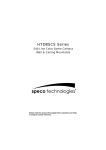
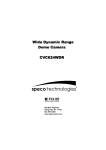
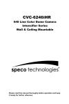
HT7715DNV (Grey Housing)
HT7715DNVW (White Housing)
560 Line Color Bullet Camera
Weatherproof, Day/Night High Resolution
Wall & Ceiling Mountable
Please read this manual thoroughly before operation and keep
it handy for further reference.
WARNING & CAUTION
CAUTION
RISK OF ELECTRIC SHOCK
DO NOT OPEN
CAUTION
:
TO REDUCE THE RISK OF ELECTRIC SHOCK
DO NOT REMOVE COVER (OR BACK).
NO US E R S E R V I C E A B L E P A RT S I N SIDE
REFER SERVICING TO QUALIFIED
SER V ICE PERSONNEL._______________
The lighting flash with an arrowhead symbol, within an equilateral triangle is
Intended to alert the user to the presence of un-insulated “dangerous voltage”
within the product’s enclosure that may be of sufficient magnitude to constitute
a risk of electric shock to persons____________________________________
The exclamation point within an equilateral triangle is intended to alert the user
to the presence of important operating and maintenance (serving) instructions
i n t h e l it e r a t u r e a cc o m p a n y i n g t h e a p p l i a n c e _ _ _ _ _ _ _ _ _ _ _ _ _ _ _ ___
I N F O R M AT I O N - T h i s e q u i p m e n t h a s b e e n t e s t e d a n d f o u n d t o c o m p a n y w i t h
l i m i t s f o r a c l a s s a d i gi t a l device Pursuant to part 15 of the FCC rules.
Th ese lim its a re d e sign e d to provide reasonable protection against harmful
I n terference W hen the equipments operated in a commercial environment.
T h i s e q u ip m e n t g e n e ra t e s , u s e s , a n d C a n R a d i a t e r a d i o f re q u e n c y e n e r g y a n d
if n o t i n s t a l l e d a n d u s e d i n a c c o r d a n c e w it h the instruction manual, may Cause
H a rm f u l in t e rf e r e n ce t o r a d i o c o m m u n i c a t io n s. O p e r a t i o n o f this equipment in a
residential area is likely to cause harmful interference in which
C a s e t h e u s e r wi l l b e r e q u i r e d t o c o r re ct t h e i n t e rf e re n ce a t h i s o wn expense .
WARNING – Change or modification not expressly approved by the manufacturer could void
the user’s authority to operate the equipment__________________________________
CAUTION : To prevent electric shock and risk of fire hazards.
DO NOT use power sources other than that specified.______
DO NOT expose this appliance to rain or moisture.000
This installation should be made by a qualified service person and should conform to all local codes.
2
CONTENTS
Package Contents
4
Precautions
5
Features
6
Camera Installation
7-11
LED Pattern
12
Specifications
13
Dimensions
14
Warranty
15
3
PACKAGE CONTENTS
Please make sure that the following items are included
in the package:
1 HT7715 Camera Series
3 Mounting Screws
1 Video test Connector
1 Wrench
Please leave this manual with the end-user for future
reference.
4
PRECAUTIONS
•
THIS CAMERA SHOULD BE ONLY INSTALLED BY QUALIFIED
PERSONNEL
•
TO PREVENT A FIRE OR ELECTRICAL HAZARD PLEASE USE
PROPER POWER CABLE
•
DO NOT CELAN THE COVER WITH AN ABRAISIVE CLEANING
MATERIAL - PLEASE USE A SOFT CLOTH OR TISSUE TO
CLEAN THE COVER
•
THERE ARE NO USER-SERVICEABLE PARTS INSIDE.
PLEASE DO NOT DISASSEMBLE THIS CAMERA OTHER THAN
TO MAKE INITIAL ADJUSTMENTS
•
PLEASE USE A UL APPROVED REGULATED 24 VOLT AC OR
12 VOLT DC POWER SUPPLY
•
PLEASE USE APPROPRIATE LOW VOLTAGE POWER CABLE
TO PREVENT FIRE OR ELECTRICAL SHOCK
•
PLEASE INSURE THAT YOUR INSTALLATION AREA CAN
SUPPORT THE WEIGHT OF THE CAMERA
•
PLEASE HANDLE THIS CAMERA CAREFULLY:
- DON’T USE A STRONG OR ABRASIVE DETERGENT WHEN
CLEANING THE CAMERA.
- DON’T EXPOSE THE CAMERA TO DIRECT SUN
5
FEATURES
•
1/3” SONY Super-Had HQ-1 , 560 TV lines of resolution
• Spilt Glass Technology – avoids IR reflections
• Auto iris DC Varifocal Lens (4mm – 9mm)
• LUX level dip switch adjusts day/night settings
to your requirements
• Dual voltage operation
• Video Test Connector for easy installation
• Built-in 18 IR LEDs (80’ Range)
and CDS sensor for day/night performance
• Controls for BLC,ELC,F/L and L/L
• Weatherproof operation
• Built-in heater extends operating range
and avoids condensation
• Excellent low light level performance
• 0.03 Lux in existing light , 0.0 Lux with IR LEDs
• Insulated mount reduces ground loops
• Cable runs through the mount for protection
6
CAMERA INSTALLATION
CONNECT POWER CABLE
1. WHEN USING 12 VOLTS DC (constant voltage 500 mA)
Power Input :RED
Center : (+)
DC 12V Power Supply
2. WHEN USING 24 VOLTS AC (40 Volt Amps)
RED(+)
AC 24V
BLACK:(-)
Power Supply
3. CONNECT VIDEO CABLE
-Connect BNC Cable To The BNC Jack.
7
CAMERA INSTALLATION
Inner Controller Details
1.Function
2.V-Phase
3.Video Test
4.LUX Level
7.DC Lens Level
5.Zoom Controller
6.Heater
5.Focus Controller
8
CAMERA INSTALLATION
1.Function
* DIP SWITCH
ON
OFF 1
(1)ELC
2
(2)BLC
3
(3)F/L
4
(4)L/L
(1) ELC- Electronic Light Compensation
ON : Camera is in Electronic Shutter Mode
OFF: Electronic Shutter is fixed at 1/60 and Auto Iris mode
is active
(2) BLC-Back Light Compensation.
BLC: If there is a strong light behind an object
the object may appear as a shadow.
Activating the BLC will minimize this effect.
The Coverage of the BLC is center plus bottom.
(3) F/L- Flicker-Less
ON : Use when the LUX changes often
OFF: Use under normal circumstances
(4) L/L- Line Lock
Locks the camera to the 60 Hz of the wall outlet.
Only operates in the 24 Volt AC mode
9
CAMERA INSTALLATION
2. V-Phase Level (UP/Down)
When desired, the vertical phase may be adjusted to synchronize the
vertical phase of the camera with other cameras in the system.
This feature is only available in 24 Volt AC operation
3. Video Test Connector
Allows the connection of a Local Monitor to make initial adjustments
to the camera
4. Lux Level
Tells the camera when to switch to the B/W night mode.
: Only one switch can be in the “on” position at a time.
ON
OFF 1
#1 STEP - The camera will switch at 1/2 lux
2
#2 STEP - The camera will switch at 1 lux
3
#3 STEP - The camera will switch at 3 lux
4
#4 STEP - The camera will switch at 5 lux
5. Zoom Controller / Focus Controller
6. Heater
7. DC Lens Level
Fine tune the Auto IRIS Lens
10
CAMERA INSTALLATION
COMPATIBILITY
“A” type Box
“B” type Box
CVCTPEXT
CVCTPLATE
★Original Mounting
Flange
Should be removed
to use CVCTPLATE
[CVCTPLATE Hole Description]
Hole 1 : CVCTPEXT
Hole 2 : Electrical Box “B” type
Hole 3 : Electrical Box “A” type
11
LED PATTERN
4-9mm VF lens
18 Mini IR LEDs (80’ Range)
12
SPECIFICATIONS
ITEM
HT7715DNV Series
Image Sensor
1/3” Sony Super-Had HQ-1 DSP CCD
Resolution
560 TV Line
Minimum illumination
0.03lux (IP Off) 0.00 LUX (IP on)
Lens Type
DC Auto Iris 4mm – 9mm (Varifocal)
CDS Sensor
Photoconductive Cells, Adjustable
Electronic Shutter
1/60 – 1/1000,000 seconds
Video Output
1.0vp-p into 75 ohms composite
TV System
NTSC
Scanning System
2 : 1 Interlace
Sync System
Line Locked / Adjustable V-Phase. Line Lock/Internal On-Off
S/N Ratio
More than 60db
IR Cut Filter
Mechanical – Auto Adjusts when required
Gamma Characteristic
0.45
Power Supply
24 Volts AC, 12 Volts DC – Dual Voltage
Power consumption
600mA
Operating Temperature
- 29℃ ~ +50℃ ( - 20℉ ~122℉)
Dimensions
2.4”W x 2.25”H x 7”L
Weight
1 lbs
Warranty
5Years
13
DIMENSIONS
Front View
Side View
14
WARRANTY
15
200 New Highway
Amityville, NY 11701
631-957-8700
www.specotech.com
VER. 090509
This manual is based on the date as shown in the right and specifications are subject
to Change without notice for quality improvement.