1
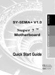
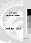
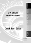
Introduction The SOYO CD Quick BIOS Setup Installation SY-5EHM/5EH5 V1.0/V1.1 Super 7 ™ Motherboard Quick Start Guide Tested To Comply With FCC Standards FOR HOME OR OFFICE USE C FC 100% POST CONSUMER RECYCLED PAPER NSTL “Year 2000 Test” Certification Letter September 23, 1998 Testing Date: September 23, 1998 Certification Date: September 23, 1998 Certification Number: NCY2000-980923-004 To Whom It May Concern: We are please to inform you that the “SY-5EHM/5EH5” system has passed NSTL Year 2000 certification test program. The Year 2000 test program tests a personal computer for its ability to support the year 2000. The “SY-5EHM/5EH5: system is eligible to carry the NSTL :Year 2000 Certification” seal. The Year 2000 certification test has been done under the following system configuration: Company Name System Model Name Hardware Revision CPU Model On Board Memory/L2 Cache System BIOS Best regards, : SOYO COMPUTER INC. : SY-5EHM/5EH5 : N/A : Intel Pentium 200/66Mhz : PC100 SDRAM DIMM 32MBx1 /1MB : Award Modular BIOS V4.51PG, An Energy Star Ally Copyright © 1984— 98, EH-1A6,07/15/1998-VP3-586B8669-2A5LES2AC-00 SPORTON INTERNATIONAL INC. Declaration of Conformity According to 47 CFR, Part 2 and 15 of the FCC Rules Declaration No.: D872907 July.10 1998 The following designated product EQUIPMENT: Main Board MODEL NO.: SY-5EH Which is the Class B digital device complies with 47 CFR Parts 2 and 15 of the FCC rules. Operation is subject to the following two conditions : (1) this device may not cause harmful interference, and (2) this device must accept any interference received, including interference that may cause undesired operation. The product was tested with the following configuration: Monitor: SONY/AK8GDM17SE2T Modem: ACEEX/IF AXDM1414 Printer: HP/DS17XU2225 Keyboard: SILITED/GYUM99SK This declaration is given for the manufacturer SOYO COMPUTER INC. No.21, Wu-Kung 5 Rd., Hsing Chuang City, Taipei Hsien, Taiwan, R.O.C. The test was carried out by SPORTON INTERNATIONAL INC. 6F, No. 106, Hsin Tai Wu Rd., Sec. 1, His Chih, Taipei Hsien, Taiwan, R.O.C. SOYO 5EHM/5EH5 V1.x Super 7 ™ Motherboard Pentium ® Class CPU (66&100MHz) supported ETEQ82C663 PCI/AGP Motherboard AT Form Factor Copyright © 1998 by Soyo Computer Inc. Trademarks: Soyo is a registered trademark of Soyo Computer Inc. All trademarks are the property of their owners. Product Rights: Product and corporate names mentioned in this publication are used for identification purposes only and may be registered trademarks or copyrights of their respective companies. Copyright Notice: All rights reserved. This manual is copyrighted by Soyo Computer Inc. You may not reproduce, transmit, transcribe, store in a retrieval system, or translate into any language, in any form or by any means, electronic, mechanical, magnetic, optical, chemical, manual or otherwise, any part of this publication without express written permission of Soyo Computer Inc. Disclaimer: Soyo Computer Inc. makes no representations or warranties regarding the contents of this manual. We reserve the right to revise the manual or make changes in the specifications of the product described within it at any time without notice and without obligation to notify any person of such revision or change. The information contained in this manual is provided for general use by our customers. Our customers should be aware that the personal computer field is the subject of many patents. Our customers should ensure that their use of our products does not infringe upon any patents. It is the policy of Soyo Computer Inc. to respect the valid patent rights of third parties and not to infringe upon or assist others to infringe upon such rights. Restricted Rights Legend: Use, duplication, or disclosure by the Government is subject to restrictions set forth in subparagraph (c)(1)(ii) of the Rights in Technical Data and Computer Software clause at 252.277-7013. About This Guide: This Quick Start Guide is for assisting system manufacturers and end users in setting up and installing the Motherboard. Information in this guide has been carefully checked for reliability; however, no guarantee is given as to the correctness of the contents. The information in this document is subject to change without notice. If you need any further information, please visit our Web Site on the Internet. The address is "http://www.soyo.com.tw". 5EHM/5EH5 V1.x Serial - Version 1.4 - Edition: August 1999 * These specifications are subject to change without notice 4 SY-5EHM/5EH5 V1.x Quick Start Guide 1 Introduction This guide is designed for all users to provide the basic steps of Motherboard setting and operation. For further information, please refer to 5EHM/5EH5 V1.x Motherboard User's Guide and Technical Reference online manual included on the CD-ROM packed with your Motherboard. Unpacking When unpacking the Motherboard, check for the following items: u The 5EHM/5EH5 V1.x Super 7 ™ Motherboard u This Quick Start Guide u The Installation CD-ROM u SOYO 3-in-1 Bonus Pack CD-ROM (Norton AntiVirus, Ghost and Virtual Drive) u One IDE Device Flat Cable u One Floppy Disk Drive Flat Cable u One dual 25-pin parallel with 25-pin flat cable and 9-pin serial with 9-pin flat cable external connector u One dual 6-pin PS/2 mouse connector with 6-pin flat cable and 9-pin serial connector with 9-pin flat cable 5 Introduction Congratulations on your purchase of the 5EHM/5EH5 V1.x Super 7 ™ Motherboard. This Quick Start Guide describes the steps for installing and setting up your new Motherboard. SY-5EHM/5EH5 V1.x Quick Start Guide SY-5EHM/5EH5 V1.x Motherboard Layout PS/2 Mouse Connector 1 Flash BIOS 3V Lithium Battery SMC 5 1 9 1 ATX Power USB1 1 Introduction 1 AT Power PRT 1COM 2 4 FDC37C669Q KB Connector JP44 1 1 3 JP5 3 5 1 1 IR1 COM 1 1 AGP Slot PCI Slot #3 PCI Slot #2 PCI Slot #1 IDE 1 IDE 2 FDC ISA Slot #3 ETEQ ISA Slot #2 ISA Slot #1 ETEQ 1 EQ82C6638 EQ82C6629 3 JP7 + Power _ LED RST (Optional) Keylock PW2 P.B. SRAM 64Kx64 1 Turbo + _ LED + HDD LED _ + TAG SRAM 2 3 4 5 6 3 SPK _ JP22 JP4 1 3 SW2 JP1 3 1 ON 2 JP9 * 4 1 12 3 4 5 1 JP12 SIMM 1 SIMM 2 DIMM 2 DIMM 1 P.B. SRAM 64Kx64 ON for model 5EHM V1.0 only (1 MB Cache) featuring two P.B. SRAM. JP10 1 3 SW1 Key Features Ø Ø Ø Ø Ø Ø 100MHz AGP Super 7 ™ platform 512KB/1MByte L2 cache Supports CPU voltage from 2.0V to 3.5V in 0.1V increments PC98, ACPI, Ultra DMA/33 Power-on by modem or alarm Supports AT or ATX power connector Ø Ø Ø Ø Ø Ø Ø 6 Supports Wake-On-LAN (WOL) Fan off in suspend mode 3 x 32-bit bus mastering PCI slots 3 x 16-bit ISA slots 1 x IrDA port Supports multiple-boot function Y2K Compliant SY-5EHM/5EH5 V1.x Quick Start Guide 2 Installation l Before handling the Motherboard, ground yourself by grasping an unpainted portion of the system's metal chassis. l Remove the Motherboard from its anti-static packaging. Hold it by the edges and avoid touching its components. l Check the Motherboard for damage. If any chip appears loose, press carefully to seat it firmly in its socket. Follow the directions in this section designed to guide you through a quick and correct installation of your new 5EHM/5EH5 V1.x Super 7 ™ Motherboard. For detailed information, please refer to 5EHM/5EH5 V1.x Motherboard User's guide and Technical Reference online manual included on the CD-ROM packed with your Motherboard. PREPARATIONS Gather and prepare all the necessary hardware equipment to complete the installation successfully: u Pentium® Class processor with cooling fan u SDRAM module u Computer case and chassis with adequate power supply unit u Monitor u Keyboard u Pointing Device (PS/2 mouse) u VGA Card u Sound Card (optional) u Speaker(s) (optional) u Disk Drives: HDD, CD-ROM, Floppy drive … u External Peripherals: Printer, Plotter, and Modem- (optional) 7 Installation To avoid damage to your Motherboard, follow these simple rules while handling this equipment: SY-5EHM/5EH5 V1.x Quick Start Guide Install the Motherboard Follow the steps below in order to perform the installation of your new 5EHM/5EH5 V1.x Super 7 ™ Motherboard. Install the CPU To mount the Pentium® processor that you have purchased separately, follow these instructions. Step 1. CPU Mount Procedure Installation 1 2 3 4 1. Lift the socket handle up to a vertical position. 2. Align the blunt edge of the CPU with the matching pinhole distinctive edge on the socket. 3. Seat the processor in the socket completely and without forcing. 4. Then close the socket handle to secure the CPU in place. Remember to connect the CPU Cooling Fan to the appropriate power connector (JP12) on the Motherboard. The fan is a key component that will ensure system stability. The fan prevents overheating, therefore prolonging the life of your CPU. 8 SY-5EHM/5EH5 V1.x Quick Start Guide Set SW2 ,JP1 for CPU Voltage SW2 is used to set the CPU core voltage, JP1 is used to select the CPU voltage type single voltage or dual voltage. Step 2. Please verify the correct voltage settings with your dealer before installation. Use the following table to set SW2, JP1 to the proper voltage value according to the specifications marked on your CPU: AMD K5 PR100 AMD K5 PR133 AMD K5 PR166 AMD K6 166 AMD K6 200 AMD K6 233 AMD K6 266 AMD K6 300 AMD K6-2 266 AMD K6-2 300 AMD K6-2 333 AMD K6-2 350 AMD K6-2 366 AMD K6-2 380 AMD K6-2 400 AMD K6-2 450 AMD K6-2 475 AMD K6-2 500 AMD K6-III 400 AMD K6-III 450 Cyrix 6x86(L) PR166+ Cyrix 6x86(L) PR200+ Cyrix 6x86MX PR166 Cyrix 6x86MX PR200 Cyrix 6x86MX PR233 Cyrix 6x86MX PR266 Cyrix MII 300 Cyrix MII 333 Cyrix MII 350 Cyrix MII 366 Intel P54C P100 Intel P54C P133 Intel P54C P166 Intel P54C P200 Intel P55C Intel P55C Intel P55C P166 P200 P233 Voltage Setting: SW2 JP1 1-2 3-4 1 2 3 4 5 3.52 V on on on on off open open The AMD K5 and K6 come in several versions with different voltages. Please verify the correct voltage settings with your dealer before installation. The most common K5 runs on 3.52V. Voltage 2.9 V on off off on off close close 3.2 V off off on on off close close 2.2 V off on off off off close close 2.2 V 2.4 V off off on off off on off off off off close close close close The AMD K6-2 and K6-III comes in several versions with different voltages. Please ask your dealer for the correct voltage. The Cyrix 6X86(L) and M¢ º come in several versions with different voltages. Please ask your dealer for the correct voltage. 2.9 V on off off on off close close 3.3 V on off on on off open open The P54C (standard Pentium®) comes in several versions with different voltages. Please ask your dealer for the correct voltage. The most common P54C runs on 3.3V. 2.8 V off off off on off close The P55C (MMX) processors have the same voltage setting. 9 close Installation Processor SY-5EHM/5EH5 V1.x Quick Start Guide Processor Voltage IDT X86 CPU C6/2-225* IDT X86 CPU 2-266 IDT X86 CPU 2-300 Voltage Setting: SW2 1 2 3 4 JP1 1-2 5 3-4 3.52 V on on on on off open open The IDT X86 CPU C6/2 comes in several versions with different. Voltage. Please ask your dealer for the correct voltage. IDT X86 CPU C6/2-200* IDT X86 CPU 2-233* Rise mP6 PR266 3.3 V on off on on off open open 2.8 V off off off on off close close Set SW1 for CPU Frequency The DIP switch SW1 enables you to assign the Frequency Multiplier, CPU Host Bus Clock, AGP Clock and PCI Clock, as shown in the following table: Step 3. Frequency Setting: SW1 Multiplier CPU Bus Clock JP7 AMD K5 PR100 1.5x 66MHz 2-3 2-3 1-2 off off off off off off AMD K5 PR133 2.0x 66MHz 2-3 2-3 1-2 on off off off off off AMD K5 PR166 2.5x 66MHz 2-3 2-3 1-2 on on off off off off AMD K6 166 2.5x 66MHz 2-3 2-3 1-2 on on off off off off AMD K6 200 3x 66MHz 2-3 2-3 1-2 off on off off off off AMD K6 233 3.5x 66MHz 2-3 2-3 1-2 off off off off off off AMD K6 266 4.0x 66MHz 2-3 2-3 1-2 on off on off off off off Processor JP9 JP10 1 2 3 4 5 6 AMD K6 300 4.5x 66MHz 2-3 2-3 1-2 on on on off off AMD K6-2 266 4.0x 66MHz 2-3 2-3 1-2 on off on off off off 4.5x 66MHz 2-3 2-3 1-2 on on on off off off 3x 100MHz 1-2 2-3 1-2 off on off off off on 5.0x 66MHz 2-3 2-3 1-2 off on on off off off AMD K6-2 300 AMD K6-2 333 3.5x 95MHz 1-2 2-3 1-2 off off off on off on AMD K6-2 350 3.5x 100MHz 1-2 2-3 1-2 off off off off off on AMD K6-2 366 5.5x 66MHz 2-3 2-3 1-2 off off on off off off on AMD K6-2 380 4.0x 95MHz 1-2 2-3 1-2 on off on on off AMD K6-2 400 4.0x 100MHz 1-2 2-3 1-2 on off on off off on AMD K6-2 450 4.5x 100MHz 1-2 2-3 1-2 on on on off off on AMD K6-2 475 5.0x 95MHz 1-2 2-3 1-2 off on on on off on AMD K6-2 500 5.0x 100MHz 1-2 2-3 1-2 off on on off off on AMD K6-III 400 4.0x 100MHz 1-2 2-3 1-2 on off on off off on AMD K6-III 450 4.5x 100MHz 1-2 2-3 1-2 on on on off off on Cyrix 6x86 MX PR 166+ 2.0x 66MHz 2-3 2-3 1-2 on off off off off off Cyrix 6x86 PR MX 200+ 2.0x 75MHz 2-3 2-3 1-2 on off off off on off Cyrix 6x86 MX PR 166 2.0x 66MHz 2-3 2-3 1-2 on off off off off off 10 SY-5EHM/5EH5 V1.x Quick Start Guide Frequency Setting: SW1 Multiplier CPU Bus Clock JP7 1 2 3 4 5 6 2.5x 66MHz 2-3 2-3 1-2 on on off off off off off off off on off JP9 JP10 Cyrix 6x86 MX PR 200 2.0x 75MHz 2-3 2-3 1-2 on Cyrix 6x86 MX PR 233 2.5x 75MHz 2-3 2-3 1-2 on on off off on off Cyrix 6x86 MX PR 266 2.5x 83MHz 1-2 2-3 1-2 on on off on on off 3.5x 66MHz 2-3 2-3 1-2 off off off off off off 3x 75MHz 2-3 2-3 1-2 off on off off on off 4.0x 66MHz 2-3 2-3 1-2 on off on off off off Cyrix MII 300 Cyrix MII 333 3.5x 75MHz 2-3 2-3 1-2 off off off off on off 3x 83MHz 1-2 2-3 1-2 off on off on on off Cyrix MII 350 3x 100MHz 1-2 2-3 1-2 off on off off off on Cyrix MII 366 2.5x 100MHz 1-2 2-3 1-2 on on off off off on off P54C P100 1.5x 66MHz 2-3 2-3 1-2 off off off off off P54C P133 2.0x 66MHz 2-3 2-3 1-2 on off off off off off P54C/P55C P166 2.5x 66MHz 2-3 2-3 1-2 on on off off off off P54C/P55C P200 P55C P233 IDT X86 CPU C6/2200 IDT X86 CPU C6/2225 3x 66MHz 2-3 2-3 1-2 off on off off off off 3.5x 66MHz 2-3 2-3 1-2 off off off off off off 3x 66MHz 2-3 2-3 1-2 off on off off off off 3x 75MHz 2-3 2-3 1-2 off on off off on off IDT X86 CPU 2-233 3.5x 66MHz 2-3 2-3 1-2 off off off off off off IDT X86 CPU 2-266 2.33x 100MHz 1-2 2-3 1-2 off on on off off on IDT X86 CPU 2-300 2.5x 100MHz 2-3 2-3 1-2 on on off off off on 3x 66MHz 2-3 2-3 1-2 off on off off off off 2.0x 100MHz 1-2 2-3 1-2 on off off off off on Rise mP6 PR266 This main board supports various CPU multiplier and host bus frequency settings. Please select the proper frequency setting based on specifications of the CPU you have purchased. System stability or components damage, in case of over-specification setting, is not guaranteed. 11 Installation Processor SY-5EHM/5EH5 V1.x Quick Start Guide Installation Jumper JP7 is used to indicate the frequency of the CPU bus clock to the ETEQ chipset. Jumpers JP9 and JP10 are used to determine that the SDRAM is running at the frequency of the CPU bus clock or at that of the AGP clock. CPU BUS Clock AGP BUS Clock PCI Clock JP7 JP9 JP10 SDRAM Clock 66MHz 75MHz 66MHz 75MHz 33MHz 37.5MHz 83MHz 55MHz 27.5MHz 95MHz 63.4MHz 31.7MHz 100MHz 66MHz 33MHz 112MHz 75MHz 37.5MHz 124MHz 82.6MHz 41.3MHz 2-3 2-3 1-2 1-2 1-2 1-2 1-2 1-2 1-2 1-2 1-2 1-2 2-3 2-3 1-2 2-3 1-2 2-3 1-2 2-3 1-2 2-3 1-2 2-3 1-2 1-2 2-3 1-2 2-3 1-2 2-3 1-2 2-3 1-2 2-3 1-2 66MHz 75MHz 55MHz 83MHz 63.4MHz 95MHz 66MHz 100MHz 75MHz 112MHz 82.6MHz 124MHz Note: Use 8ns or faster SDRAM modules (for PC100) when SDRAM is set to run at the frequency of 95/100MHz. Select the CPU Burst Mode There are two types of CPU burst modes according to manufacturer design: Ø Interleave Burst (CPU: Intel P54C/P55C, AMD K5/K6/K6-2/K6-III,IDT X86 CPU, Rise mP6) Ø Linear Burst (CPU: Cyrix 6x86/L/MX/M II) Step 4. Interleave CPU Burst Mode JP22 Setting Intel ™P54C/P55C AMD ™K5/K6/K6-2/K6-III IDT X86 CPU, Rise mP6 When using Intel 1 or AMD CPUs. 2 (Default) 3 Linear Cyrix ™6x86/L/MX/MII When using Cyrix type of CPU. 1 2 3 If you are using a Cyrix ™ 6x86/L/MX/M II series CPU, set the burst mode to Linear by shorting pin 2-3 on jumper JP22, and follow the following steps to select the correct Linear burst mode in BIOS: 1. 2. 3. 4. 5. During the boot-up initial sequence, press the [Delete] key to enter the BIOS setup menu. Select the [CHIPSET FEATURES SETUP] section in BIOS. In the [CHIPSET FEATURES SETUP] sub-menu, set the [Linear Burst] field to [Enabled]. Press [Esc] to return to the BIOS main menu. Then choose [Save & Exit Setup] to re-boot your computer. 12 SY-5EHM/5EH5 V1.x Quick Start Guide Attach Connectors This section tells how to connect internal peripherals and power supply to the Motherboard. Step 5. Internal peripherals include IDE devices (HDD, CD-ROM), Floppy Disk Drive, Front Panel Devices (Turbo LED, Internal Speaker, Reset Button, IDE LED, and KeyLock Switch.), Wake-On-LAN card, VGA card, Sound Card, and other devices. For more details on how to connect internal and external peripherals to your new 5EHM/5EH5 V1.x Super 7 ™ Motherboard, please refer to 5EHM/5EH5 V1.x Motherboard User's Guide and Technical Reference online manual on CD-ROM. Connectors and Plug-ins Power LED Key Lock + _ USB Connect your USB devices to this header. Power LED Speaker + _ Wake-On-LAN Header: JP44 Pin1 Pin2 Pin3 5VSB GND MP-Wakeup Pin5 IRTX Keylock Pin1 Pin2 Pin3 GND GND Control Pin Speaker + _+ _ Pin1 Pin2 Pin3 Pin4 5V NC NC Speaker out Reset PWRBT Turbo LED HDD LED TB LED HDD LED PWRBT RESET Pin1 Pin2 Pin1 Pin2 Pin1 Pin2 Pin1 Pin2 LED LED Power Power LED Anode LED Anode GND GND Cathode Cathode On/Off Good ATX Power On/Off: PWRBT Pin1 5V Pin2 NC Connect your power switch to this header (momentary switch type). To turn off the system, please press this switch and hold down for longer than 4 seconds. ATX Power Supply: ATX PW Attach the ATX Power cable to this connector. Please make sure the ATX power supply can take at least 720mA load on the 5V standby lead (5VSB), if you want to use the advanced power management functions like Power-On by modem or WOL. Note: Use only ONE type of power supply. If an AT power supply is used, do not attach an ATX power supply. AT Power Cable Connect the AT Power cable to this connector. If you use AT power supply. 13 Installation IrDA (Infrared Device Header): IR1 Pin2 Pin3 Pin4 None IRRX GND CPU Cooling Fan: JP12 Pin1 Pin2 Pin3 GND 12V NC Pin1 VCC SY-5EHM/5EH5 V1.x Quick Start Guide Configure Memory Your board comes with one SIMM Bank (2 modules) and two DIMM sockets, providing support for up to 512MB of main memory using DIMM modules from 8MB to 256MB. For 66MHz host bus CPUs use 12ns or faster DIMM modules; for 83MHz host bus CPUs use 8ns modules. Step 6. Memory Configuration Table MEMORY CONFIGURATION RAM Type Single RAM Module Size (MB) SIMM Bank DIMM Banks Bank 1,2 DIMM 1 DIMM 2 FPM/EDO/BEDO EDO/SDRAM EDO/SDRAM 4/8/16/32/64 8/16/32/64/128/256 8/16/32/64/128/256 Note: 1. You must install two SIMM modules to complete the SIMM Bank 2. Do not use FPM or EDO type of SIMM/DIMM if you already use SDRAM. Installation 3. Do not install SIMM Bank and DIMM 1 at the same time. Clear CMOS Clear the CMOS memory by momentarily shorting pin 2-3 on jumper JP5, and then by shorting pin 1-2 to retain new settings. This jumper can be easily identified by its white colored cap. Step 7. CMOS Clearing JP5 Setting Clear CMOS Data 1 short pin 2-3 to clear the CMOS 2 3 Retain CMOS Data Short pin 1-2 to retain new settings 1 2 3 Note: You must unplug the ATX power cable from the ATX power connector when performing the CMOS Clear operation. 14 SY-5EHM/5EH5 V1.x Quick Start Guide 3 Quick BIOS Setup After the hardware installation is complete, turn the power switch on, then press the <DEL> key during the system diagnostic checks to enter the Award BIOS Setup program. The CMOS SETUP UTILITY will display on screen. Then, follow these steps to complete the quick BIOS setup. Step 1. Select [LOAD SETUP DEFAULT] Select the “LOAD SETUP DEFAULT”menu and type “Y”at the prompt to load the BIOS optimal setup. Step 2. Select [STANDARD CMOS SETUP] Set [Date/Time] and [Floppy drive type], then set [Hard Disk Type] to “Auto”. Select [SAVE & EXIT SETUP] Press <Enter> to save the new configuration to the CMOS memory, and continue the boot sequence. Quick BIOS Setup Step 3. 15 SY-5EHM/5EH5 V1.x Quick Start Guide The SOYO CD 4 The SOYO-CD will NOT autorun if you use it on an Operating System other than Windows 9x or NT. Your SY-5EHM/5EH5 V1.x Motherboard comes with a CD-ROM labeled "SOYO CD." The SOYO CD contains (1) the user's manual file for your new Motherboard, (2) the drivers software available for installation, and (3) a database in HTML format with information on SOYO Motherboards and other products. Step 1. Insert the SOYO CD into the CD-ROM drive The SOYO CD The SOYO CD will auto-run, and the SOYO CD Start Up Menu will be shown as below. (SOYO CD Start Up Program Menu) If you use Windows 95/98, the SOYO CD Start Up Program automatically detects which SOYO Motherboard you own and displays the corresponding model name. Step 2. Read SOYO [5EH V1.0] Manual Click the Read Manual button to open the user's manual file of your Motherboard. 16 SY-5EHM/5EH5 V1.x Quick Start Guide Please note that if the Start Up program was unable to determine which SOYO Motherboard you own, the manual selection menu will pop up, as shown below. Then select the user's manual file that corresponds to your Motherboard model name and click OK. SOYO CD Manuals Please select your manual in the box below and click OK. 686 boards: 586 boards: 5EH V1.0 OK Back (Manual Selection Menu) The user's manual files included on the SOYO CD are in PDF (Postscript Document) format. In order to read a PDF file, the appropriate Acrobat Reader software must be installed in your system. Note: The Start Up program automatically detects if the Acrobat Reader utility is already present in your system, and otherwise prompts you on whether or not you want to install it. You must install the Acrobat Reader utility to be able to read the user's manual file. Follow the instructions on your screen during installation, then once the installation is completed, restart your system and re-run the SOYO CD. Install Drivers and Utilities The following describes the best way of installing Windows 95 or Windows 98 on your 5EHM/5EH5 V1.x Motherboard: Ø The following BIOS default settings should not be changed: 1. The ‘OnChip USB Controller’item under ‘Chipset features Setup’is set to enabled. 2. The ‘USB Assigned IRQ’item under ‘PnP/PCI Configuration is set to enabled. You MUST have these two items enabled for Windows 95/98 to run properly on your system. Ø Install Windows 95/98 Ø If you installed Windows 95 you will now need to upgrade your USB driver by running the following program on your Windows CD: Win95/OSR2/Usbsupp/USBsupp.exe 17 The SOYO CD Step 3. SY-5EHM/5EH5 V1.x Quick Start Guide Ø After installation of windows, you will need to install the ETEQ drivers. Follow the instruction below. Click the Enter SOYO CD button to display the list of drivers that can be installed on your Motherboard. The start-up program displays the drivers available for the 5EHM/5EH5 V1.x and the Windows version you use. Click the Install drivers button to display the list of drivers that can be installed on your Motherboard. The start-up program displays the drivers available for the 5EHM/5EH5 V1.x. Driver Installation Please select the driver you want to install and click OK, You will have to restart your system after installation. Only the drivers that are relevant to your board are displayed initially. ETEQ 4 in 1 driver package Display all drivers on the SOYO CD Cancel OK (Driver Installation Menu) The SOYO CD However, to display the list of all drivers software available with SOYO Motherboards, click the Display all drivers on the SOYO CD button. Please make sure to install only the drivers adapted to your system, or otherwise this may cause system malfunctions. A short description of all available drivers follows: Ø ETEQ 4in1 driver package The 4 in 1 driver package includes all drivers your motherboard needs. After selecting this driver package, one driver will be installed automatically (the IRQ remapping utility), the other three are installed if selected. By default all three drivers are selected. A description of the 4 drivers follows: Bus Master PCI IDE Driver This driver will speed up the data-transfer rate to and from the harddisk. 18 SY-5EHM/5EH5 V1.x Quick Start Guide AGP VxD Driver This driver must be installed in order to be able to make use of the on-board AGP Video functionality. ETEQ Chipset Functions Registry This driver will make the necessary changes to the Windows registry, in order to make sure that Windows has no problems recognizing your ETEQ chipset. IRQ remapping utility (This driver is installed automatically) This utility will remap the IRQ lines to make sure that everything functions properly under Windows. Select which driver you want to install and click OK, or click Cancel to return to the main menu. When the installation program of a driver starts running the SOYO-CD will exit. Note: When the installation is complete, most drivers require to restart your system before they can become active. If you want to see all the drivers available on the SOYO –CD, click the Display all drivers on the SOYO CD button. Do NOT install drivers that are not suitable for your board, otherwise your system may crash. Step 4. Check the Latest Releases Click the 'Check the latest Releases' button to go the SOYO Website to automatically find the latest BIOS, manual and driver releases for your motherboard. This button will only work if your computer is connected to the internet through a network or modem connection. Make sure to get your modem connection up before clicking this button. Step 5. Enter the SOYO CD Click the Enter SOYO CD button to enter the SOYO HTML database. The Start Up program will activate the default HTML browser installed on your system (for example, Internet Explorer or Netscape) to display the contents of the SOYO CD. The SOYO CD The SOYO CD contains useful information about your Motherboard and other SOYO products available. For your convenience, this information is available in HTML format, similar to the format widely used on the Internet. 19 SY-5EHM/5EH5 V1.x Quick Start Guide The SOYO CD Note: If no HTML browser is installed on your system, the Start Up program will prompt you on whether or not you would like to install the Internet Explorer* browser. Click YES to install the HTML browser. After the installation is complete, please restart your system. Then re-run the SOYO CD and you will be able to browse the SOYO HTML database. (* Internet Explorer is a Microsoft Trademark) 20 SY-5EHM/5EH5 V1.x Quick Start Guide How to contact us: n If you are interested in our products, please contact the SOYO sales department in the region you live. n If you require Technical Assistance, please contact our Technical Support in the region you live. SOYO prefers Email as communication medium, remember to always add to the email the country that you live in. SOYO Taiwan SOYO USA No. 21 Wu-Kung 5 Rd., Hsin Chuang City, Taipei Hsien, Taiwan 41484 Christy Street, Fremont, CA 94538 Region Covered: US and Canada Region Covered: Taiwan and AsiaPacific. (Including Australia). Web Site: www.soyo.com.tw Sales: Tel: 886-2-22903300-318 Fax: 886-2-22983322 E-mail: [email protected] Web Site: www.soyousa.com, www.soyo.com Sales: Tel: 510-226-7696 Fax: 510-226-9218 Email : [email protected] Technical Support: Tel: 510-226-7696 Fax: 510-226-9218 Email : [email protected] Technical Support: Fax: 886-2-22983322 E-mail: [email protected] SOYO Europe BV Signaalrood 19, 2718 SH Zoetermeer The Netherlands Region Covered: Europe except Germany, Austria and Switserland Web Site: www.soyo.nl, www.soyoeurope.com SOYO (U.K.) LTD. Unit 7, Alice Way, Hounslow Business Park, Hanworth Road, Hounslow, TW3 3UD Region Covered: United Kingdom and Republic of Ireland Web Site: www.soyo.co.uk Sales: Tel : +44 (0)181 569 4111 Fax: +44 (0)181 569 4134 E-mail: [email protected] Sales: Tel: +31-69-3637500 Fax: +31-79-3637575 Email: [email protected] Technical Support: Tel : +31-79-3637500 Fax: +31-79-3637575 Email: [email protected] Technical Support: Tel : +44 (0)181 569 4111 Fax: +44 (0)181 569 4134 21 SY-5EHM/5EH5 V1.x Quick Start Guide E-Mail: [email protected] Sales: tel: 852-27109810 fax: 852-27109078 E-mail: [email protected] SOYO Deutschland GmbH August-Wilhelm-Kuhnholz-Str. 15 D-26135 Oldenburg Technical Support: tel: 852-27109810 fax: 852-27109078 E-mail: [email protected] Region Covered: Germany, Austria and Switzerland. (Zustandig fur Deutschland, Osterreich, Schweiz) Web Site: www.saat.de, www.soyosaat.com, www.soyo-saat.de Vertrieb Mainboards, Notebooks und SoyoCom Produkte: E-Mail: [email protected] Fon: +49-(0)441/20910-31/33 Fax: +49-(0)441/203422 SOYO China (Gin Mei Jei) Region Covered: All of China Sales: Tel: 86-10-62510089 fax: 86-10-62510388 E-mail: [email protected] Technischer Support: E-Mail: [email protected] Fon: +49-(0)441/20910-40 Fax: +49-(0)441/203422 Technical Support: Tel: 86-10-62510089 fax: 86-10-62510388 E-mail: [email protected] SOYO KOREA Region Covered: Korea SOYO Japan Region Covered: Japan Sales: Tel : 82-2-716-2850 Fax : 82-2-704-2619 E-mail : [email protected] Web site: www.soyo.co.jp Sales: Tel: 81-3-33682188 Fax: 81-3-33682199 E-mail: [email protected] Technical Support: tel : 82-2-717-4392 fax : 82-2-712-5853 e-mail : [email protected] Technical Support: Tel: 81-3-33682188 Fax: 81-3-33682199 E-mail: [email protected] SOYO Hong Kong Region Covered: Hong Kong Web Site: www.soyo.com.hk 22 Edition: August 1999 Version 1.4 SY-5EHM/5EM5 V1.0/V1.1 SERIAL