1
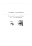
Introduction
The SOYO CD Quick BIOS Setup Installation
SY-5EMA+
Super 7 ™
Mainboard
Quick Start Guide
Tested To Comply
With FCC Standards
FOR HOME OR OFFICE USE
C
FC
100%
POST CONSUMER
RECYCLED PAPER
SOYO ™
SY-5EMA+ Super7 ™ Mainboard
Pentium® Class CPU supported
ETEQ82C663 PCI/AGP Mainboard
ATX Form Factor
Copyright © 1998 by Soyo Computer Inc.
Trademarks:
Soyo is a registered trademark of Soyo Computer Inc. All trademarks are the property of their
owners.
Product Rights:
Product and corporate names mentioned in this publication are used for identification purposes
only and may be registered trademarks or copyrights of their respective companies.
Copyright Notice:
All rights reserved. This manual is copyrighted by Soyo Computer Inc. You may not reproduce,
transmit, transcribe, store in a retrieval system, or translate into any language, in any form or by
any means, electronic, mechanical, magnetic, optical, chemical, manual or otherwise, any part of
this publication without express written permission of Soyo Computer Inc.
Disclaimer:
Soyo Computer Inc. makes no representations or warranties regarding the contents of this
manual. We reserve the right to revise the manual or make changes in the specifications of the
product described within it at any time without notice and without obligation to notify any
person of such revision or change. The information contained in this manual is provided for
general use by our customers. Our customers should be aware that the personal computer field is
the subject of many patents. Our customers should ensure that their use of our products does not
infringe upon any patents. It is the policy of Soyo Computer Inc. to respect the valid patent rights
of third parties and not to infringe upon or assist others to infringe upon such rights.
Restricted Rights Legend:
Use, duplication, or disclosure by the Government is subject to restrictions set forth in
subparagraph (c)(1)(ii) of the Rights in Technical Data and Computer Software clause at
252.277-7013.
About This Guide:
This Quick Start Guide is for assisting system manufacturers and end users in setting up and
installing the mainboard. Information in this guide has been carefully checked for reliability;
however, no guarantee is given as to the correctness of the contents. The information in this
document is subject to change without notice.
If you need any further information, please visit our Web Site on the Internet. The address is
"http://www.soyo.com.tw".
* These specifications are subject to change without notice.
Version 1.1 Edition: September 1998
2
SY-5EMA+ Quick Start Guide
1
Introduction
This guide is designed for all users to provide the basic steps of mainboard setting and
operation. For further information, please refer to SY-5EMA+ Mainboard User's Guide and
Technical Reference online manual included on the CD-ROM packed with your Mainboard.
Unpacking
When unpacking the Mainboard, check for the following items:
Ø
The SY-5EMA+ Mainboard
Ø
This Quick Start Guide
Ø
The Installation CD-ROM
Ø
One IDE Device Flat Cable
Ø
One Floppy Disk Drive Flat Cable
3
Introduction
Congratulations on your purchase of the SY-5EMA+ PCI/AGP Mainboard. This Quick Start
Guide describes the steps for installing and setting up your new mainboard.
SY-5EMA+ Quick Start Guide
SY-5EMA+ Mainboard Layout
CPUFAN
PS/2 Mouse
PS/2 KB
Connector Connector
JP1
1
Introduction
*
JP2
USB1
P.B. SRAM
64Kx64
USB2
JP30
8
6
4
2
P.B. SRAM
64Kx64
ATX Power
JP44
1
7
5
3
1
(Optional)
TAG 32Kx8
IDE 2 IDE 1
ETEQ
3
EQ82C6638
WOL
Header
FDC
3
1
JP9
JP8
JP10
ON
DIMM 1
SW1
DIMM3
DIMM 2
AGP Slot
1
PCI Slot #1
SMC
FDC37C669Q
IR
1
1
1
3V
Lithium
Battery
5
PCI Slot #2
JP5
3
Flash BIOS
1
ETEQ
EQ82C6629
PCI Slot #4
CHAFAN
1
PCI Slot #3
+
SPK
PCI Slot #5
_
Keylock
ISA Slot #2
Power
LED
Key Features
Ø
Ø
Ø
Ø
Ø
Super 7 TM Platform
512KByte/1MByte L2 cache
Supports CPU voltage from 2.0v to 3.5v
in 0.1v increments
PC97, ACPI, Ultra DMA/33MHz
Power-on by modem or RTC alarm
Ø
Ø
Ø
Ø
Ø
Ø
4
Turbo
LED
PW2
+
_
ISA Slot #1
HDD LED
Supports Wake On LAN (WOL)
Fan-off in Suspend mode
5x32-bit bus mastering PCI slots
2xUSB ports, 1xIrDA port
Supports multiple-boot function
DMI utility
RST
SY-5EMA+ Quick Start Guide
2
Installation
l
Before handling the Mainboard, ground yourself by grasping an unpainted portion of
the system's metal chassis.
l
Remove the Mainboard from its anti-static packaging. Hold it by the edges and avoid
touching its components.
l
Check the Mainboard for damage. If any chip appears loose, press carefully to seat it
firmly in its socket.
Follow the directions in this section designed to guide you through a quick and correct
installation of your new SY-5EMA+ Super 7 ™ Mainboard. For detailed information, please
refer to SY-5EMA+ Mainboard User's guide and Technical Reference online manual
included on the CD-ROM packed with your Mainboard.
PREPARATIONS
Gather and prepare all the necessary hardware equipment to complete the installation
successfully:
u Pentium® class processor with cooling fan
u DRAM memory modules
u Computer case and chassis with adequate power supply unit
u Monitor
u Keyboard
u Pointing Device (PS/2 mouse)
u VGA Card
u Sound Card (optional)
u Speaker(s) (optional)
u Disk Drives: HDD, CD-ROM, Floppy drive …
u External Peripherals: Printer, Plotter, and Modem- (optional)
5
Installation
To avoid damage to your Mainboard, follow these simple rules while handling
this equipment:
SY-5EMA+ Quick Start Guide
Install the Mainboard
Follow the steps below in order to perform the installation of your new SY-5EMA+ Super
7 ™ Mainboard.
Step 1.
Install the CPU
To mount the Pentium® class processor that you have purchased separately, follow these
instructions.
Installation
CPU Mount Procedure
1
2
3
4
1.
Lift the socket handle up to a vertical position.
2.
Align the blunt edge of the CPU with the matching pinhole distinctive edge on the
socket.
3.
Seat the processor in the socket completely and without forcing.
4.
Then close the socket handle to secure the CPU in place.
Remember to connect the CPU Cooling Fan to the appropriate power
connector on the Mainboard. The fan is a key component that will ensure
system stability. The fan prevents overheating, therefore prolonging the life of
your CPU.
6
SY-5EMA+ Quick Start Guide
Step 2.
Set JP30 ,JP1 and JP2 for CPU Voltage
JP30 is used to set the CPU core voltage, JP1 and JP2 are used to select the CPU voltage
type single voltage or dual voltage.
Please verify the correct voltage settings with your dealer before installation. Use the
following table to set JP30, JP1 and JP2 to the proper voltage value according to the
specifications marked on your CPU:
AMD K5 PR100
AMD K5 PR133
AMD K5 PR166
Voltage
3.5 V
1-2
3-4
5-6
7-8
close
close
close
close
JP1
JP2
close
open
The AMD K5 and K6 come in several versions with different voltages.
Please verify the correct voltage settings with your dealer before
installation. The most common K5 runs on 3.52V.
AMD K6
AMD K6
166
200
2.9 V
close
open
open
close
open
close
AMD K6
233
3.2 V
open
open
close
close
open
close
2.2 V
open
close
open
open
open
close
AMD K6 266
AMD K6 300
AMD K6-2 266
AMD K6-2 300
AMD K6-2 333
AMD K6-2 350
Cyrix 6x86(L) PR166+
Cyrix 6x86(L) PR200+
Cyrix 6x86MX PR166
Cyrix 6x86MX PR200
Cyrix 6x86MX PR233
Cyrix 6x86MX PR266
Cyrix MII 300
Cyrix MII 333
Cyrix MII 350
Intel P54C P100
Intel P54C P133
Intel P54C P166
Intel P54C P200
Intel P55C
Intel P55C
Intel P55C
P166
P200
P233
The Cyrix 6X86(L) and M¢ º
come in several versions with different
voltages. Please ask your dealer for the correct voltage.
2.9 V
close
open
open
close
open
close
3.3 V
close
open
close
close
close
open
The P54C (standard Pentium ®) comes in several versions with different
voltages. Please ask your dealer for the correct voltage. The most
common P54C runs on 3.3V.
2.8 V
open
open
open
close
open
The P55C (MMX) processors have the same voltage setting.
7
close
Installation
Voltage Setting: JP30
Processor
SY-5EMA+ Quick Start Guide
Step 3.
Set SW1 for CPU Frequency
The DIP switch SW1 enable you to assign the Multiplier and Bus Clock, as shown in the
following table:
Installation
Frequency Setting: SW1
Multiplier
CPU
Bus
Clock
AMD K5 PR100
1.5x
66MHz
1-2
2-3
2-3
off
off
off
off
off
off
AMD K5 PR133
2.0x
66MHz
1-2
2-3
2-3
on
off
off
off
off
off
AMD K5 PR166
2.5x
66MHz
1-2
2-3
2-3
on
on
off
off
off
off
AMD K6 166
2.5x
66MHz
1-2
2-3
2-3
on
on
off
off
off
off
AMD K6 200
3x
66MHz
1-2
2-3
2-3
off
on
off
off
off
off
AMD K6 233
3.5x
66MHz
1-2
2-3
2-3
off
off
off
off
off
off
AMD K6 266
4.0x
66MHz
1-2
2-3
2-3
on
off
on
off
off
off
AMD K6 300
4.5x
66MHz
1-2
2-3
2-3
on
on
on
off
off
off
AMD K6-2 266
4.0x
66MHz
1-2
2-3
2-3
on
off
on
off
off
off
AMD K6-2 300
3x
100MHz
1-2
1-2
2-3
off
on
off
off
off
on
AMD K6-2 333
3.5x
95MHz
1-2
1-2
2-3
off
off
off
on
off
on
AMD K6-2 350
3.5x
100MHz
1-2
1-2
2-3
off
off
off
off
off
on
Cyrix 6x86 MX PR 166+
2.0x
66MHz
1-2
2-3
2-3
on
off
off
off
off
off
Cyrix 6x86 PR MX 200+
2.0x
75MHz
1-2
2-3
2-3
on
off
off
off
on
off
Cyrix 6x86 MX PR 166
2.0x
66MHz
1-2
2-3
2-3
on
off
off
off
off
off
2.5x
66MHz
1-2
2-3
2-3
on
on
off
off
off
off
off
Processor
Cyrix 6x86 MX PR 200
JP10 JP8
JP9
1
2
3
4
5
6
2.0x
75MHz
1-2
2-3
2-3
on
off
off
off
on
Cyrix 6x86 MX PR 233
2.5x
75MHz
1-2
2-3
2-3
on
on
off
off
on
off
Cyrix 6x86 MX PR 266
2.5x
83MHz
1-2
1-2
2-3
on
on
off
on
on
off
3.5x
66MHz
1-2
2-3
2-3
off
off
off
off
off
off
3x
75MHz
1-2
2-3
2-3
off
on
off
off
on
off
4.0x
66MHz
1-2
2-3
2-3
on
off
on
off
off
off
Cyrix MII 300
Cyrix MII 333
Cyrix MII 350
3.5x
75MHz
1-2
2-3
2-3
off
off
off
off
on
off
3x
83MHz
1-2
1-2
2-3
off
on
off
on
on
off
2.5x
100MHz
1-2
1-2
2-3
on
on
off
off
off
on
3x
100MHz
1-2
1-2
2-3
off
on
off
off
off
on
off
P54C
P100
1.5x
66MHz
1-2
2-3
2-3
off
off
off
off
off
P54C
P133
2.0x
66MHz
1-2
2-3
2-3
on
off
off
off
off
off
P54C/P55C P166
2.5x
66MHz
1-2
2-3
2-3
on
on
off
off
off
off
3x
66MHz
1-2
2-3
2-3
off
on
off
off
off
off
3.5x
66MHz
1-2
2-3
2-3
off
off
off
off
off
off
P54C/P55C P200
P55C
P233
This main board supports various CPU multiplier and host bus frequency settings.
Please select the proper frequency setting based on specifications of the CPU you have
purchased. System stability or components damage, in case of over-specification setting, is
not guaranteed.
8
SY-5EMA+ Quick Start Guide
CPU BUS
Clock
AGP BUS
Clock
PCI Clock JP10 JP8
JP9
SDRAM
Clock
66MHz
75MHz
66MHz
75MHz
33MHz
37.5MHz
83MHz
55MHz
27.5MHz
95MHz
63.4MHz
31.7MHz
100MHz
66MHz
33MHz
112MHz
75MHz
37.5MHz
124MHz
82.6MHz
41.3MHz
2-3
2-3
1-2
2-3
1-2
2-3
1-2
2-3
1-2
2-3
1-2
2-3
66MHz
75MHz
55MHz
83MHz
63.4MHz
95MHz
66MHz
100MHz
75MHz
112MHz
82.6MHz
124MHz
1-2
1-2
2-3
1-2
2-3
1-2
2-3
1-2
2-3
1-2
2-3
1-2
2-3
2-3
1-2
1-2
1-2
1-2
1-2
1-2
1-2
1-2
1-2
1-2
Note: Use 8ns or faster SDRAM modules (for PC100) when SDRAM is set to run at
the frequency of 95/100MHz.
Step 4.
Configure Memory
Your board comes with three DIMM sockets, providing support for up to 768MB of main
memory using DIMM modules from 8MB to 256MB. For 66MHz host bus CPUs use 12ns or
faster DIMM modules; for 83MHz host bus CPUs use 8ns modules.
Memory Configuration Table
MEMORY
CONFIGURATION
RAM Type
Single RAM
Module Size (MB)
DIMM Banks
DIMM 1
FPM/EDO/SDRAM
DIMM 2
DIMM 3
FPM/EDO/SDRAM
FPM/EDO/SDRAM
8/16/32/64/128/256
8/16/32/64/128/256
8/16/32/64/128/256
Note: Do not use FPM or EDO type of SIMM/DIMM if you already use SDRAM.
9
Installation
JP8 is used to indicate the frequency of the CPU bus clock to the ETEQ chipset.
JP9 and JP10 are used to determine that the SDRAM is running at the frequency of the
CPU bus clock or the AGP clock.
SY-5EMA+ Quick Start Guide
Step 5.
Attach Connectors
This section tells how to connect internal peripherals and power supply to the Mainboard.
Internal peripherals include IDE devices (HDD, CD-ROM), Floppy Disk Drive, Chassis Fan,
Front Panel Devices (Turbo LED, Internal Speaker, Reset Button, IDE LED, and KeyLock
Switch.), Wake-On-LAN card, VGA card, Sound Card, and other devices.
For more details on how to connect internal and external peripherals to your new SY-5EMA+
Super 7 ™ Mainboard, please refer to SY-5EMA+ Mainboard User's Guide and Technical
Reference online manual on CD-ROM.
Installation
Connectors and Plug-ins
Wake-On-LAN Jumper: JP44
Connect the WOL cable from your LAN card to
JP44.
TB LED
SPK
RESET
Connect your
Connect the
Turbo LED to this speaker cable to
jumper
this jumper
IrDA (Infrared Device
Connector): IR
CPU Cooling Fan : CPUFAN
Chassis Cooling Fan : CHAFAN
Connect you cooling Fan cable to this connector
IDE LED
KB-LOCK
Connect the reset Connect the IDE Connect the
button to this
device LED to this Power LED and
jumper
jumper
the KB Lock
switch to this
jumper
ATX Power On/Off: PWRBT
ATX Power Cable : ATX PW
Connect your IrDA device to this Connect your power switch to Attach the ATX Power cable to
connector
this jumper (momentary switch this connector
type)
CMOS Clear
Clear the CMOS memory by shorting pin 2-3 on jumper JP5, and then by shorting pin 1-2 to
retain new settings. This jumper can be easily identified by its white colored cap.
CMOS Clearing
JP5 Setting
Clear CMOS Data
short pin 2-3 to
clear the CMOS
1
2
3
Retain CMOS Data (Default)
Short pin 1-2 to
retain new settings
1
2
3
Note: You must unplug the ATX power cable from the ATX power connector when
performing the CMOS Clear operation.
10
SY-5EMA+ Quick Start Guide
3
Quick BIOS Setup
After the hardware installation is complete, turn the power switch on, then press the <DEL>
key during the system diagnostic checks to enter the Award BIOS Setup program. The
CMOS SETUP UTILITY will display on screen. Then, follow these steps to complete the
quick BIOS setup.
Step 1.
Select [LOAD SETUP DEFAULT]
Select the “LOAD SETUP DEFAULT”menu and type “Y”at the prompt to load the BIOS
optimal setup.
Step 2.
Select [STANDARD CMOS SETUP]
Set [Date/Time] and [Floppy drive type], then set [Hard Disk Type] to “Auto”.
Step 3.
Select [SAVE & EXIT SETUP]
Quick BIOS
Setup
Press <Enter> to save the new configuration to the CMOS memory, and continue the boot
sequence.
11
SY-5EMA+ Quick Start Guide
4
The SOYO CD
Your SY-5EMA+ Super 7 ™ Mainboard comes with a CD-ROM labeled "SOYO CD." The
SOYO CD contains the user's manual file for your new Mainboard, the drivers software
available for installation, and a database in HTML format with information on SOYO
Mainboards and other products.
Step 1.
Insert the SOYO CD into the CD-ROM drive
The SOYO CD
The SOYO CD will auto-run, and the SOYO CD Start Up Menu will display as shown below.
(SOYO CD Start Up Program Menu)
The SOYO CD Start Up Program automatically detects which SOYO Mainboard you own
and displays the corresponding model name.
Step 2.
Read SOYO [model name] Manual
Click the Read Manual button to open the user's manual file of your Mainboard.
12
SY-5EMA+ Quick Start Guide
Please note that if the Start Up program was unable to determine which SOYO Mainboard
you own, the manual selection menu will pop up, as shown below. Then select the user's
manual file that corresponds to your Mainboard model name and click OK.
SOYO CD Manuals
Please select your manual In the box below
and click OK.
5EMA+
OK
Back
(Manual Selection Menu)
Note: The Start Up program automatically detects if the Acrobat Reader utility is already
present in your system, and otherwise prompts you on whether or not you want to install it.
You must install the Acrobat Reader utility to be able to read the user's manual file. Follow
the instructions on your screen during installation, then once the installation is completed,
restart your system and re-run the SOYO CD.
Step 3.
Installation procedure for Windows 95/98
The following describes the best way of installing Windows 95 or Windows 98 on your 5EMA+
mainboard:
Ø The following BIOS default settings should not be changed:
1. The ‘USB Controller’item under ‘Chipset features’is set to enabled.
2. The ‘USB Assigned IRQ’item under ‘PnP/PCI Configuration is set to enabled.
You MUST have these two items enabled for Windows 95/98 to run properly on your system.
Ø Install Windows 95/98
Ø After installation of windows, you will need to install the ETEQ drivers. Follow the instruction
below.
13
The SOYO CD
The user's manual files included on the SOYO CD are in PDF (Postscript Document) format.
In order to read a PDF file, the appropriate Acrobat Reader software must be installed in your
system.
SY-5EMA+ Quick Start Guide
Click the Install Drivers button to display the list of drivers that can be installed on your mainboard.
The start-up program displays the drivers available for the 5EMA+ and the Windows version you use.
For Windows 95 four drivers will be listed (see ‘Driver Installation Menu’below), for Windows 98 three
drivers will be listed (the ACPI drivers will be left out). We recommend you to install all drivers, and to
do so in the right sequence (top to bottom).
The SOYO CD
If you want to see all the drivers available on the SOYO –CD, click the Display all drivers on the
SOYO CD button. Do NOT install drivers that are not suitable for you board, otherwise your system
may crash.
(Driver Installation Menu)
Select which driver you want to install and click OK, or click Cancel to return to the main
menu. When the installation program of a driver starts running the SOYO-CD will exit. After
finishing the installation, restart the SOYO-CD and install the next driver.
Note: Once you have selected a driver, the system will automatically exit the SOYO CD to
begin the driver installation program. When the installation is complete, most drivers require
to restart your system before they can become active.
14
SY-5EMA+ Quick Start Guide
Step 4.
Enter the SOYO CD
Click the Enter SOYO CD button to enter the SOYO HTML database. The Start Up program
will activate the default HTML browser installed on your system (for example, Internet
Explorer or Netscape) to visualize the contents of the SOYO CD.
(SYO CD HTML Database in English*)
(* The list of menu options may vary between languages)
Note: If no HTML browser is installed on your system, the Start Up program will prompt you
on whether or not you would like to install the Internet Explorer* browser. Click YES to install
the HTML browser. After the installation is complete, please restart your system. Then re-run
the SOYO CD and you will be able to browse the SOYO HTML database.
(* Internet Explorer is a Microsoft Trademark)
15
The SOYO CD
The SOYO CD contains useful information about your Mainboard and other SOYO products
available in as many as eleven different languages. For your convenience, this information is
available in HTML format, similar to the format widely used on the Internet.
Edition: Sep. 1998
Version 1.1
5EMA+ SERIAL
International Headquarters
Soyo Computer Inc., (Taiwan)
Tel: 886-2-2290-3300
Fax: 886-2-2298-3322
Web Site: http://www.soyo.com.tw
E-mail: [email protected]
USA Branch Office
Soyo Tek Inc., (USA)
Tel: (408) 452-7696
Fax: (408) 573-7696
Web Site: http://www.soyousa.com
E-mail: [email protected]
SOYO Europe
Soyo Europe B.V., (Holland)
Tel: 31-79-3637500
Fax: 31-79-3637575
Web Site: http://www.soyo-europe.com
http://www.soyo.nl
E-mail: [email protected]
Germany Branch Office
SAAT Technology GmbH, (Germany)
Tel: 49-(0)441-204044
Fax: 49-(0)441-203422
Web Sites:http://www.saat.de
http://www.soyo-saat.de
http://www.soyo-saat.com
Email: [email protected]
UK Branch Office
SOYO (U.K.) Ltd.
Tel: 44-(0)181-569 4111
Fax: 44-(0)181-5694134
Web Site: http://www.soyo.nl
E-mail: [email protected]
Japan Branch Office
SOYO Computer (Japan)
Tel: 81-3-33682188
Fax: 81-3-33682199
Web Site: http://www.soyo.co.jp
E-mail: [email protected]
Hong Kong Branch Office
Soyo Hong Kong LTD(H.K)
Tel: 852-2710-9810
Fax: 852-2710-9078
Web Site: http://www.soyo.com.hk
E-mail: [email protected]