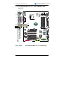
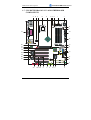
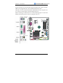
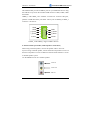
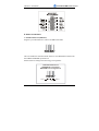
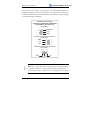
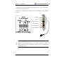
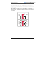
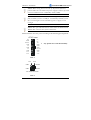
1
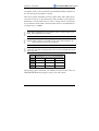
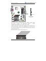
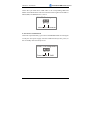
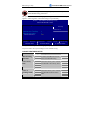
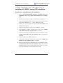
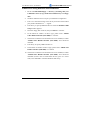
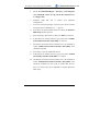
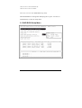
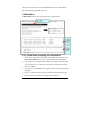
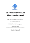
1. 2. 3. 4. 5. 6. 7. 8. Please read the users guide before proceeding with your installations. Serious damage may occur if the procedure is not followed properly. This motherboard does not support CPUs with a Vcore higher than 1.6 volts. Please make sure the CPU you are using 1.6 volts or is below. Check the CPU specification before you insert it in the CPU socket. AGP cards running at 3.3v are not supported. Only AGP cards running at 1.5v (most 4x or 8x AGP cards) are supported on this motherboard. Please make sure that your memory modules are inserted correctly. They can go in only one way, and should fit completely in the socket without sticking out. Failure to do so will damage your motherboard and memory module. An ATX12V power supply (Power supply for Pentium 4 system) is required for the system to operate normally. (Preferably 350 watts for minimal loading or 400 watts for fully loaded system). If you have any problem getting your system to work, please follow the troubleshooting tips in your user manual. On some motherboards, the actual chipset cooler may differ from the chipset cooler as shown on the picture or on the box. However, the chipset fan on the motherboard is of the same quality and will work just as well as the one shown in the picture. (The chipset cooler is as sufficient as the chipset fan based on a different design.) For answers to Technical questions, please visit SOYO tech support link at http://www.soyogroup.com/support and http://www.soyogroup.com/kb. SY-P4I875P DRAGON 2 V1.0 Motherboard **************************************************** mPGA Socket 478 Processor supported Intel 875P AGP/PCI 533/800 MHz Front Side Bus supported ATX Form Factor **************************************************** User's Manual SOYO™ SY-P4I875P DRAGON 2 V1.0 Copyright © 2004 by SOYO Group Inc. Trademarks: SOYO is the registered trademark of SOYO Group Inc. All trademarks are the properties of their owners. Product Rights: All names of the product and corporate mentioned in this publication are used for identification purposes only. The registered trademarks and copyrights belong to their respective companies. Copyright Notice: All rights reserved. This manual has been copyrighted by SOYO Group Inc. No part of this manual may be reproduced, transmitted, transcribed, translated into any other language, or stored in a retrieval system, in any form or by any means, such as by electronic, mechanical, magnetic, optical, chemical, manual or otherwise, without permission in writing from SOYO Group Inc. Disclaimer: SOYO Group Inc. makes no representations or warranties regarding the contents of this manual. We reserve the right to amend the manual or revise the specifications of the product described in it from time to time without obligation to notify any person of such revision or amend. The information contained in this manual is provided to our customers for general use. Customers should be aware that the personal computer field is subject to many patents. All of our customers should ensure that their use of our products does not infringe upon any patents. It is the policy of SOYO Group Inc. to respect the valid patent rights of third parties and not to infringe upon or to cause others to infringe upon such rights. Disclaimer: Please be advised that some SOYO motherboards are designed with overclocking features and may allow users to run the components beyond manufacturer's recommended specifications. Overclocking beyond manufacturer's specifications is not recommended nor endorsed by SOYO Group, Inc. and will void your manufacturer's warranty. Overclocking beyond manufacturer's specifications is not encouraged and should be assumed at the user's own risk. Unsafe overclocking can damage the user's system or cause serious personal injury. If the user is unsure or in doubt about overclocking, please seek professional advise. SOYO, Inc. is not responsible for any direct or indirect damage resulting from overclocking. Restricted Rights Legend: Use, duplication, or disclosure by the Government is subject to restrictions set forth in subparagraph (c)(1)(ii) of the Rights in Technical Data and Computer Software clause at 252.277-7013. About This Guide: This Quick Start Guide can help system manufacturers and end users in setting up and installing the Motherboard. Information in this guide has been carefully checked for reliability; however, to the correctness of the contents there is no guarantee given. The information in this document is subject to amend without notice. For further information, please visit our Web Site on the Internet. The address is "http://www.soyogroup.com". FC Tested To Comply C With FCC Standards Edition: February 2005 FOR HOME OR OFFICE USE Version V1.1 POST CONSUMER P4I875P DRAGON 2 V1.0 Platinum Edition SERIES 100% RECYCLED PAPER iii Table of Contents SY-P4I875P DRAGON 2 V1.0 Table of Contents CHAPTER 1 MOTHERBOARD DESCRIPTION.....................................1 1-1 INTRODUCTION ...........................................................................1 1-2 UNPACKING THE MOTHERBOARD...........................................1 1-3 KEY FEATURES .............................................................................3 1-4 HANDLING THE MOTHERBOARD.............................................5 1-5 ELECTROSTATIC DISCHARGE PRECAUTIONS.......................5 1-6 SY-P4I875P DRAGON 2 V1.0 MOTHERBOARD LAYOUT.........6 1-7 SY-P4I875P DRAGON 2 V1.0 MOTHERBOARD COMPONENTS ...7 CHAPTER 2 HARDWARE INSTALLATION ........................................14 2-1 PREPARATIONS...........................................................................14 2-2 INSTALLATION GUIDE ..............................................................15 A. IDE Device Installation (HDD, CD-ROM) ...........................................22 B. Floppy Drive Installation .......................................................................25 C. Front Panel Connections ........................................................................26 D. Back Panel Connections .........................................................................29 E. Other Connections ..................................................................................32 F. ATX12V Power Supply............................................................................39 G. Center & Bass Select Connector (JP30) ................................................41 H. CMOS Clear (JP5) .................................................................................42 2-3 QUICK BIOS SETUP ....................................................................44 CHAPTER 3 BIOS SETUP UTILITY ......................................................46 3-1 SOYO COMBO FEATURE...........................................................49 3-2 STANDARD CMOS SETUP.........................................................60 3-3 ADVANCED BIOS FEATURES ...................................................63 3-4 ADVANCED CHIPSET FEATURES ............................................68 3-5 INTEGRATED PERIPHERALS ...................................................70 3-6 POWER MANAGEMENT SETUP...............................................76 3-7 PNP/PCI CONFIGURATION SETUP...........................................80 3-8 PC HEALTH STATUS...................................................................83 iv Table of Contents SY-P4I875P DRAGON 2 V1.0 3-9 LOAD FAIL-SAFE DEFAULTS ...................................................84 3-10 LOAD OPTIMIZED DEFAULTS .................................................85 3-11 SUPERVISOR PASSWORD .........................................................86 3-12 USER PASSWORD .......................................................................87 CHAPTER 4 DRIVERS INSTALLATION ..............................................89 CHAPTER 5 USB 2.0 DRIVER INSTALLATION..................................97 CHAPTER 6 ALI M5281 DRIVER INSTALLATION............................98 CHAPTER 7 ALI M5281 SERIAL ATA DRIVER INSTALLATION .....101 CHAPTER 8 ICH5R (SATA1/SATA2) SETUP INFORMATION .......104 APPENDIX A ALI M5283..........................................................................106 APPENDIX B FLASHING BIOS ROM....................................................114 APPENDIX C TROUBLESHOOTING ....................................................118 APPENDIX D CONTACT INFORMATION ...........................................127 v Motherboard Description SY-P4I875P DRAGON 2 V1.0 Chapter 1 MOTHERBOARD DESCRIPTION 1-1 INTRODUCTION The SY-P4I875P DRAGON 2 V1.0 AGP/PCI Motherboard is a high-performance Socket 478 processor, ATX form-factor system board. SY-P4I875P DRAGON 2 V1.0 uses the Intel 875P Chipset technology. This Motherboard is fully compatible with industry standards and adds many technical enhancements. 1-2 UNPACKING THE MOTHERBOARD When unpacking the Motherboard, check for the following items: The SY-P4I875P DRAGON 2 V1.0 Intel 875P AGP/PCI Motherboard The user manual The Installation CD-ROM SOYO Bonus Pack CD-ROM Three IDE Device ATA 100 Flat Cable One Floppy Disk Drive Flat Cable Four Serial ATA cables 1 Motherboard Description SY-P4I875P DRAGON 2 V1.0 One SPDIF Audio Connector Card (optional) One Back panel ΣBOX (optional) Warning: Do not unpack the Motherboard from its anti-static packaging until you are ready to install it. Like most electronic equipment, your Motherboard may be damaged by electrostatic discharge. To avoid permanent damage to components ground yourself while working by using a grounding strap. Otherwise, ground yourself frequently by touching the unpainted portion of the computer chassis to drain the static charges. Handle the Motherboard carefully, holding it by the edges. You are now ready to start the installation. 2 Motherboard Description SY-P4I875P DRAGON 2 V1.0 1-3 KEY FEATURES CPU Chipset Memory AGP PCI Super I/O Supports Intel® mPGA Socket 478 processors: ¾ Pentium® 4 with and without Hyperthreading, Northwood, Prescott (533/800MHz FSB) ¾ Pentium® 4 Celeron ¾ SOYO COMBO Setup CMOS setup menu for complete and easy changing of your CPU settings in CMOS setup, making jumpers obsolete. Note: CPU with higher than 1.6 volts are not supported. Intel® 875P / ICH5R Chipset ¾ The SY-P4I875P DRAGON 2 V1.0 supports PC2700 and PC3200 DDR (non-registered and ECC) memory modules. ¾ SOYO COMBO Setup menu, to fully configure your memory settings. 1x AGP master 4x/8x slot (1.5v only) 5x 32-bit bus master PCI slots ITE IT8712F-A Super I/O controller supporting : ¾ Floppy disk controller ¾ Parallel port (SPP, EPP and ECP compliant) ¾ 2x 16550A compatible RS232 serial ports ¾ IrDA compatible infrared port ¾ PS/2 Keyboard and mouse ¾ Hardware monitor for monitoring temperatures, voltages and fan speeds in the system. ¾ PC/SC (Personal Computer Smart Card Working Group) Standard compliant smart card controller 3 Motherboard Description Storage USB 2.0 Sound Network IEEE1394 BIOS Software Industry standards SY-P4I875P DRAGON 2 V1.0 ¾ ICH5R integrated Serial ATA controller supporting up to 2x UDMA 150 hard disks in normal or RAID 0 mode ¾ ALi M5281 Serial ATA RAID controller supporting up to 2x UDMA 150 hard disks in normal or RAID (0 or 1) mode. ¾ ICH5R Integrated Parallel ATA controller supporting up to 4x UDMA 33/66/100 Parallel ATA devices. ¾ ALi M5281 PCI to IDE RAID controller for support for up to 4x UDMA 33/66/100/133 parallel ATA hard disks in normal or RAID (0, 1 or 0+1) mode. 8x USB 2.0 compliant ports (4 on rear IO panel, 4x motherboard connectors. Onboard CMedia CM8738 6 channel PCI Hardware Audio Onboard Intel 10/100 MBps 100Base-T and 1000BASE-T (Gigabit) Ethernet controller, supporting Wake-On-Lan (WOL) Onboard VIA VT6306 IEEE1394 Firewire controller with 1x rear IO panel connector and 2x motherboard connectors. ¾ Power Failure resume function to allow the system to turn on or off after a power failure, which is indispensable for server systems. ¾ Wake On Ring and Power On by Alarm to allow your system to wake up from suspend or power on through the modem or RTC alarm. ¾ Multiple boot, allowing your system to boot from for example CD-ROM ¾ SOYO Hardware Doctor allowing you to fully monitor and control your system ¾ SOYO Bonus Pack CD-ROM containing free bonus software. This motherboard is compliant with the following industry standards : ¾ Microsoft PC99 ¾ FCC ¾ ACPI 4 Motherboard Description SY-P4I875P DRAGON 2 V1.0 1-4 HANDLING THE MOTHERBOARD To avoid damage to your Motherboard, follow these simple rules while unpacking: ¾ Before handling the Motherboard, ground yourself by grasping an unpainted portion of the system's metal chassis. ¾ Remove the Motherboard from its anti-static packaging. Hold the Motherboard by the edges and avoid touching its components. ¾ Check the Motherboard for damage. If any chip appears loose, contact your dealer or our tech support immediately. Warning: Do not apply power if the Motherboard appears damaged. If the motherboard is damaged, contact your dealer immediately. 1-5 ELECTROSTATIC DISCHARGE PRECAUTIONS Make sure to ground yourself before handling the Motherboard or other system components. Electrostatic discharge can easily damage the components. Note that you must take special precautions when handling the Motherboard in dry or air-conditioned environment. To protect your equipment from electrostatic discharge, take the following precautions: ¾ Do not remove the anti-static packaging until you are ready to install. ¾ Ground yourself before removing any system component from its protective anti-static packaging. (To ground yourself, grasp the expansion slot covers or other unpainted portions of the computer chassis.) ¾ Frequently ground yourself while working or use a grounding strap. ¾ Handle the Motherboard by its edges and avoid touching its components. 5 Motherboard Description SY-P4I875P DRAGON 2 V1.0 1-6 SY-P4I875P DRAGON 2 V1.0 MOTHERBOARD LAYOUT PS/2 KB PS/2 Mouse Connector Connector DDR_B1 DDR_B2 DDR_A1 DDR_A2 I/O CHIP 1394USB SMCARD 14 5 13 SIRCON 1 2 COM A ATX Power COM B PRT LAN Connector +12V Power FDC1 USBLAN MIC IN Audio out 7 1 8 Audio in 2 J30 AGPDET LAN CHIP 3V Lithium Battery PCI Slot #1 SATA2 PCI Slot #2 AUDIO CHIP JP5 IDE 1 CMOS Cl ear Jumper PCI Slot #3 SATA1 JP30 1 2 AUXIN 5 1 4 1394 CHIP ALi CHIP CDIN 1 1 PCI Slot #4 SATA3 SATA4 PCI Slot #5 IDE 4 15 10 FW2 Back Panel 6 10 6 FW1 1 IDE 3 2 10 GAMEPORT 6 10 6 USB20_1 USB20_2 SY-P4I875P DRAGON 2 V1.0 Platform 6 IDE 2 Motherboard Description SY-P4I875P DRAGON 2 V1.0 1-7 SY-P4I875P DRAGON 2 V1.0 MOTHERBOARD COMPONENTS A B C D E F G H I J K L M AL N AK AJ AI AH O AG Q P AF AE R AD S T AC AB AA Z Y 7 X W V U Motherboard Description A B C D E F G SY-P4I875P DRAGON 2 V1.0 Microphone and LAN Status LED Connector (J30) This connector allows you to extend your microphone connector and LAN Status LED to your front panel. Check the MIC & LED Connector (J30) paragraph on page 36 for a lay-out of this header. +12V Power Connector This is where the Power Supply's +12V ATX connector goes. For a lay-out of this connector please check the F. ATX12V Power Supply paragraph on page 39. AGP Slot This is the AGP expansion slot for your video card. Note that it can only work with 1.5v AGP cards. For more information, check the Step 3 Installation of Expansion Cards paragraph on page 19. Socket 478 Connector This is the Zif (Zero Insertion Force) socket for your Pentium 4 or Celeron CPU. For more information, check the Step 1 Install the CPU paragraph on page 15. Intel 875P North Bridge Chip The Intel® 875P chipset features support for an 800 MHz Front Side Bus (FSB) and implements Intel® Performance Acceleration Technology (PAT) with dual-channel DDR400 memory configurations to get incredible performance from the memory interface. Optimized to support the Intel® Pentium® 4 Processor with Hyper-Threading Technology†, the 875P chipset adds intelligence to help manage and prioritize multiple threads received from the microprocessor. 3V Lithium Battery This battery supplies power to the CMOS RAM. As long as the battery supplies enough power, the contents of your CMOS RAM will be valid. CMOS RAM contents are configured by CMOS setup, and can be cleared by JP5. For more details on this check the H. CMOS Clear (JP5) paragraph on page 42. CPU Cooling Fan (CPUFAN1, 2) connectors With these connectors you can attach the CPU fan or fans to your motherboard. They supply power and (in the case of CPUFAN1) allow you to monitor the speed of the FAN via the SOYO Hardware Monitor software or via CMOS setup. For more details on the lay-out of these connectors, check the 2. Cooling Fan Installation paragraph on page 33. 8 Motherboard Description H I J K L M N SY-P4I875P DRAGON 2 V1.0 Chassis Cooling Fan (CHAFAN3) connectors This connector is to connect your chassis fan to your motherboard. This motherboard supports up to 3 chassis fans. Please check the (2) Chassis Cooling Fan (CHAFAN1, CHAFAN2, CHAFAN3) paragraph on page 34 for more details. DDR DIMM Banks These 4, 184 pin memory slots are to install your system memory in. They support up to 4 GB of memory. For more details check the Step 2 Install Memory Module paragraph on page 18. ITE IT8712F-A Super I/O Chip The IT8712F-A is a Low Pin Count Interface-based highly integrated Super I/O. The IT8712F-A provides the most commonly used legacy Super I/O functionality plus the latest Environment Control initiatives, such as H/W Monitor, Fan Speed Controller, ITE's 'SmartGuardian' function and Smart Card Reader Interface. The device's LPC interface complies with Intel 'LPC Interface Specification Rev. 1.0'. The IT8712F-A meets the 'Microsoft® PC98 & PC99 System Design Guide' requirements, and is ACPI & LANDesk compliant. Serial Infrared (IrDA) device header This header allows you to connect an IrDA receiver to the motherboard. You can find the lay-out in the 1. Standard Infrared (SIRCON) paragraph on page 32. Smart Card Reader connector This connector allows you to connect a smart card reader to the PC/SC, ISO 7816 compliant onboard smart card reader. The paragraph 3. Smart Card Reader on page 35 contains more information on the lay-out of this header. ATX Power Supply connector This connector is to connect the ATX connector of your ATX12V compliant power supply to the motherboard. For more details on this connector, please check the F. ATX12V Power Supply paragraph on page 39. Floppy Disk Drive (FDD) connector This 34 pins connector is to connect your floppy drive to. Check for more details in the B. Floppy Drive Installation paragraph on page 25. 9 Motherboard Description O P Q R S T U SY-P4I875P DRAGON 2 V1.0 Chassis Cooling Fan (CHFAN2) connector This connector is to connect your third chassis fan to your motherboard. This motherboard supports up to 3 chassis fans. Please check the (2) Chassis Cooling Fan (CHAFAN1, CHAFAN2, CHAFAN3) paragraph on page 34 for more details. Flash BIOS This chip contains the system BIOS firmware, and is software upgradable. It's size is 4Mbit. For updates of your Flash BIOS, please go to http://www.soyogroup.com/. For details on how to setup your BIOS, please go to the BIOS SETUP UTILITY chapter on page 46. Bus Mastering EIDE/ATAPI Ports These connectors are to attach your IDE devices to. Each connector can support up to 2 IDE devices, 1 master and 1 slave. Please check the IDE Device Installation (HDD, CD-ROM) paragraph on page 22 for more details. CMOS Clear Jumper (JP5) This jumper allows you to clear your CMOS RAM contents in order to reset your system configuration. . For more details on this check the H. CMOS Clear (JP5) paragraph on page 42. Front Panel connectors (J25) This header allows you to connect the switches and LEDs on your front panel. Please check the C. Front Panel Connections chapter on page 26 for more details and lay-outs. 5V Stand-By Indicator LED The ATX 12V power supply will always supply a 5V standby voltage to your motherboard so that it can power on via for example Wake On Lan technology. This LED shows that your ATX 12V power supply is supplying this standby voltage to your motherboard. IDE RAID Ports These IDE ports (IDE 3 and IDE 4) can be used as normal IDE port or in a RAID configuration and are controlled by the ALi M5281chip. ATAPI devices will not work on these ports. For more details, please check the IDE Device Installation (HDD, CD-ROM) paragraph on page 22. 10 Motherboard Description V W X Y Z AA AB SY-P4I875P DRAGON 2 V1.0 ALi M5281 Serial /Parallel ATA RAID chip The M5281 provides personal computer systems with PCI device solution of the highest integration: It includes two Serial-ATA Host controllers for supporting a total of 2 ports, one fully Parallel-ATA Host controller for supporting two channels. SATA Connectors These connectors allow you to attach one UDMA 150 hard disk to each connector. Note that SATA 3 and 4 are controlled by the ALi M5281 chip, and can support RAID 0 and 1. For more information on these connectors check the IDE Device Installation (HDD, CD-ROM) paragraph on page 22. USB 2.0 connectors These connectors support 2 USB 2.0 ports per connector. For details on the lay-out, please check the 5. Universal Serial Bus (USB1/USB2, USB3/USB4, USB20_1/USB20_2) paragraph on page 31. Chassis Cooling Fan (CHAFAN1) connector This connector is to connect your chassis fan to your motherboard. This motherboard supports up to 3 chassis fans. It allows you to monitor the speed of CHAFAN1 in CMOS setup or by using the SOYO Hardware Monitor software. Please check the (2) Chassis Cooling Fan (CHAFAN1, CHAFAN2, CHAFAN3) paragraph on page 34 for more details. CD-IN connector This connector is to attach your analog audio output channel from your CDROM or DVD drive to your motherboard. Please check the 4. CD Line-in (CDIN) paragraph on page 35 for more details. GAMEPORT connector This connector is to attach your gameport connector to. Gameports are used to connect for example joysticks to. For more details check the paragraph on page 31. SPK5 connector This connector is to connect the speaker attached to your case to your motherboard. Please check the 7. SPK5 paragraph on page 37 for more details. 11 Motherboard Description AC AD AE AF AG AH AI SY-P4I875P DRAGON 2 V1.0 IEEE1394 Firewire connector These connectors allow you to attach IEEE 1394 connectors or devices to the motherboard. The lay-out can be found in the 8. IEEE 1394 (Firewire) Connector (FW1/FW2) paragraph on page 38. VIA VT6306 IEEE1394 Firewire chip The VT6306 IEEE 1394 OHCI Host Controller provides high performance serial connectivity. It implements the Link and Phy layers for IEEE 1394-1995 High Performance Serial Bus and 1394a Draft 4.0. It is compliant with 1394 Open HCI 1.0 and 1.1 with DMA engine support for high performance data transfer via a 32-bit bus master PCI host bus interface. Center & Bass select connector (JP30) Because some speaker manufacturers connect their center and bass speakers different, this jumper allows you to select how your center and bass speakers are connected. See the G. Center & Bass Select Connector (JP30) paragraph on page 41 for more details. AUX-IN connector This connector allows you to attach a second CDROM analog audio out output to your mainboard. Please check the 5. AUX-IN (AUXIN) paragraph on page 36 for more details. CMedia CMI 8738 PCI 6 Channel hardware audio chip The CMI 8738 chip is a 2/4/6 Channel PCI hardware audio chip, which uses the HRTF 3D positional audio technology. It is SB Pro compatible and supports SPDIF IN/OUT. It also has a DLS (DownLoadable Sound) wave table music synthesizer which supports DirectMusic. 32 bit PCI slots These are the motherboard's 3.3v busmastering PCI slots, compliant to PCI specification v2.2. Intel 82801ER South Bridge chip ICH5R platforms enable the next generation desktop storage interface with integration of Serial ATA (SATA). The ICH5R also supports eight, high-speed USB 2.0 ports and integrates an Alert Standard Format (ASF) System Management controller for network manageability. The ICH5R includes enhancements for ACPI 2.0 compliant power management logic. ICH5R supports RAID 0 function. 12 Motherboard Description AJ AK AL SY-P4I875P DRAGON 2 V1.0 Intel 82547EI LAN chip The Intel® 82547 family of controllers are highly integrated Platform LAN Connect devices combining 10BASE-T, 100BASE-TX and 1000BASE-T (Gigabit) physical layer capabilities, and providing a core ingredient of the enabling solution for the integrated networking connectivity in Intel® I/O Controller Hub based platforms. It supports a single interface fully compliant with the IEEE 802.3/802.3u/802.3 standard. The IEEE 802.3 standard for 1000BASE-TX defines networking over two pairs of Category 5 unshielded twisted pair cable. AGP DET LED This LED lights up when an AGP 3.3v card is inserted in the system. If this LED lights up, your system will not work, since AGP 3.3v cards are not supported. Back panel connectors These connectors allow you to attach the external devices to the back of your PC. Please check the D. Back Panel Connections paragraph on page 29 for more details. 13 Hardware Installation SY-P4I875P DRAGON 2 V1.0 Chapter 2 HARDWARE INSTALLATION Congratulations on your purchase of SY-P4I875P DRAGON 2 V1.0 Motherboard. You are about to install and connect your new Motherboard. Note: Do not unpack the Motherboard from its protective anti-static packaging until you have made the following preparations. 2-1 PREPARATIONS Gather and prepare all the following hardware equipment to complete the installation successfully: 1. Socket mPGA478 processor with CPU cooling fan. (CPUs with a VCORE higher than 1.6 volts are not supported) 2. DDR memory module(s) 3. A computer case with an adequate power supply unit (350W for a minimally loaded system or 400W for a fully loaded system). 4. Monitor 5. Keyboard 6. Pointing Device (mouse) 7. Disk Drives: HDD, CD-ROM, Floppy drive… 8. External Peripherals: Printer and Modem (optional) 9. VGA Card (AGP or PCI) Note: This M/B only supports 1.5V AGP VGA cards! 3.3V AGP cards are not supported ! 14 Hardware Installation SY-P4I875P DRAGON 2 V1.0 2-2 INSTALLATION GUIDE We will now begin the installation of the Motherboard. Please follow the step-by-step procedure designed to lead you to a complete and correct installation. Step1- Install the Central Processing Unit (CPU). Step2- Install memory modules. Step3- Install expansion cards. Step4- Connect cables, case wires, and power supply. Step5- Power on and enter BIOS setup. Step6- Install supporting software tools. See Chapter 4 for more info. Warning: Turn off the power to the Motherboard, system chassis, and peripheral devices before performing any work on the Motherboard or system. BEGIN THE INSTALLATION Step 1 Install the CPU CPU Mount Procedure: To mount the Pentium® 4 Socket mPGA478 processor that you have purchased separately, follow these instructions. 1. Lift the socket handle up to a vertical position. 15 Hardware Installation SY-P4I875P DRAGON 2 V1.0 2. Align the blunt edge of the CPU with the matching pinhole distinctive edge on the socket. 3. Seat the processor in the socket completely and without forcing. 16 Hardware Installation SY-P4I875P DRAGON 2 V1.0 4. Then close the socket handle to secure the CPU in place. Remember to connect the CPU Cooling Fan to the appropriate power connector on the Motherboard. The fan is a key component that will ensure system stability. The fan prevents overheating, therefore prolonging the life of your CPU. CPU Fan Installation Your Socket 478 processor kit comes with a cooling fan. Mount the fan on the processor according to the instructions provided by the manufacturer. The fan is a key component that will ensure system stability. The fan prevents overheating, therefore prolonging the life of your CPU. Note: Remember to connect the fan to the appropriate power source. 17 Hardware Installation SY-P4I875P DRAGON 2 V1.0 Step 2 Install Memory Module This motherboard supports two Dual Channels to your memory. Note that you can use normal DDR memory for Dual Channel to work. Also note that for Dual Channel to work 2 or 4 modules of equal size and specifications have to be installed. The largest memory capacity possible is 4GB. On this motherboard, DRAM speed can be set independent from the CPU front side bus speed. Note that when installing 4GB of memory, your total memory will be less than 4GB. The reason for this is that the BIOS, PCI and AGP cards claim part of your CPUs address space. Memory Configuration Table If you want to use the Dual Channel feature, please follow the memory configuration table below: 18 Hardware Installation DDR Slots DDR_A1 SY-P4I875P DRAGON 2 V1.0 DDR_A2 DDR_B1 DDR_B2 Performance 128 bit Present Present 128 bit 128 bit Present Present Present Present Present Present Installing your memory in a combination different from the table above will still allow your system to work. The Dual Channel feature will not work then however. This motherboard also supports ECC (error correcting code) memory DDR modules. Memory frequency Table Depending on the front side bus (FSB) frequency of the CPU, you can run memory of different speeds. Please look at the table below for details: CPU FSB (MHz) 400 533 800 Memory Frequency (MHz) 266 266 or 333 400 or 320* DDR DIMM Type PC2100 PC2100 or PC2700 PC3200 or PC2700 * When using a 800 MHz FSB CPU and PC2700 DDR DIMMs, the memory frequency runs at 320 MHz (instead of 333 MHz) due to chipset limitations. Step 3 Installation of Expansion Cards The motherboard has 1 AGP slot and 5 PCI slots. 1. Read the related expansion card’s instruction document before inserting the expansion card into the computer. 2. Press the expansion card firmly into the expansion slot on the motherboard. 3. Make sure the metal contacts on the card are seated in the slot. 4. Replace the screw to secure the slot bracket of the expansion card. 5. Install required driver for the operating system you use. 19 Hardware Installation SY-P4I875P DRAGON 2 V1.0 AGP Slot This motherboard only support 1.5V AGP cards (4X/8X cards). If 3.3V AGP card is used, the system will not power-on and the AGPDET LED will lit. AGPDET LED (When AGPDET LED is lit, it means a 3.3V AGP card is being used.) If you use a 3.3V AGP card, the system will not power-on and the AGPDET LED will lit. 20 Hardware Installation SY-P4I875P DRAGON 2 V1.0 PCI Slots PCI IRQ Assignment The following table shows which PCI IRQs are used by which onboard device. A B C D E F G • AGP ALi M5281 CMedia 8738 PCI Audio VIA VT6306 IEEE1394 Intel 82547EI 10/100/1G Ethernet PCI Slot 1 PCI Slot 2 PCI Slot 3 PCI Slot 4 PCI Slot 5 Intel 82801ER (ICH5R) USB 2.0 • • • • • • • • • • 21 Hardware Installation SY-P4I875P DRAGON 2 V1.0 Step 4 Connect cables, case wire and power supply A. IDE Device Installation (HDD, CD-ROM) IDE 1 IDE 2 Pin -1 Primary Secondary IDE IDE IDE 4 IDE 3 SATA2 SATA1 SATA3 SATA4 This Motherboard offers two primary (IDE1, IDE3) IDE device connectors, 2 secondary IDE device connectors (IDE2, IDE4) and 4 tertiary serial ATA ports. IDE1 and IDE2 can support up to four high-speed Ultra DMA 33/66/100 HDD or CD-ROM. IDE3 and IDE4 can support up to 4 high speed Ultra DMA 33/66/100/133 HDD. SATA1~4 can support up to 4 ATA 150 SATA hard disks. 22 Hardware Installation SY-P4I875P DRAGON 2 V1.0 IDE1,2 are controlled by the 82801ER (ICH5R), IDE3,4 are controlled by the ALi M5281, SATA1,2 are controlled by the 82801ER (ICH5R) and SATA3,4 are controlled by the ALi M5281 controller.. There are 8 parallel ATA HDD connectors (IDE1, IDE2, IDE3, IDE4) and 4 serial ATA connectors on the motherboard. IDE3 and IDE4 are provided for IDE RAID or standard IDE function. SATA1, SATA2, SATA 3 and SATA4 are provided for SATA RAID or standard SATA function. This Motherboard can support up to 12 HDDs. Note: IDE2 and SATA2 are not bootable, SATA1, SATA3, SATA4 and IDE1, IDE3 and IDE4 are bootable. Note1: SATA1 and SATA2 can only support RAID 0 Note2: RAID 0 function of ICH5R can only work under Windows XP, other operating system is not supported. Note: Only Windows XP can use SATA1, SATA2, IDE1 and IDE2 at the same time. All other operating systems can use any