1
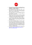
DVI USB Dual Mode LAN or Cat 5 KVM
Extender with Audio - 330ft (100m)
SV565LANDUA
*actual product may vary from photos
DE: Bedienungsanleitung - de.startech.com
FR: Guide de l'utilisateur - fr.startech.com
ES: Guía del usuario - es.startech.com
IT: Guida per l'uso - it.startech.com
NL: Gebruiksaanwijzing - nl.startech.com
PT: Guia do usuário - pt.startech.com
For the most up-to-date information, please visit: www.startech.com
Manual Revision: 06/06/2012
FCC Compliance Statement
This equipment has been tested and found to comply with the limits for a Class A digital
device, pursuant to part 15 of the FCC Rules. These limits are designed to provide reasonable
protection against harmful interference in a residential installation. This equipment generates,
uses and can radiate radio frequency energy and, if not installed and used in accordance with
the instructions, may cause harmful interference to radio communications. However, there
is no guarantee that interference will not occur in a particular installation. If this equipment
does cause harmful interference to radio or television reception, which can be determined by
turning the equipment off and on, the user is encouraged to try to correct the interference by
one or more of the following measures:
• Reorient or relocate the receiving antenna.
• Increase the separation between the equipment and receiver.
• Connect the equipment into an outlet on a circuit different from that to which the receiver
is connected.
• Consult the dealer or an experienced radio/TV technician for help.
Use of Trademarks, Registered Trademarks, and other Protected Names and Symbols
This manual may make reference to trademarks, registered trademarks, and other
protected names and/or symbols of third-party companies not related in any way to
StarTech.com. Where they occur these references are for illustrative purposes only and do not
represent an endorsement of a product or service by StarTech.com, or an endorsement of the
product(s) to which this manual applies by the third-party company in question. Regardless
of any direct acknowledgement elsewhere in the body of this document, StarTech.com hereby
acknowledges that all trademarks, registered trademarks, service marks, and other protected
names and/or symbols contained in this manual and related documents are the property of
their respective holders.
Instruction Manual
Table of Contents
Introduction.............................................................................................1
Packaging Contents.................................................................................................................................. 1
System Requirements............................................................................................................................... 1
Connecting Your KVM Extender............................................................3
Preparing Your Site.................................................................................................................................... 3
Local Extender Unit Installation............................................................................................................ 3
Remote Extender Unit Installation....................................................................................................... 3
Connecting the Local Extender to the Remote Extender............................................................ 4
Powering the Units.................................................................................................................................... 4
LEDs................................................................................................................................................................. 5
Troubleshooting......................................................................................................................................... 6
Pairing a Local Extender to a Remote Extender.............................................................................. 10
Audio.............................................................................................................................................................. 11
Compatibility............................................................................................................................................... 11
Setup & Equipment................................................................................................................................... 11
Specifications...........................................................................................12
Specifications Continued.......................................................................13
Technical Support...................................................................................14
Warranty Information.............................................................................14
Instruction Manual
i
Introduction
The SV565LANDUA Dual Mode USB DVI KVM Console Extender over Cat5 (100m) or
LAN lets you control a USB & DVI-D PC or KVM switch over an IP Local Area Network, or
by direct Cat5 (or better) cable connection, up to 100 meters (330 feet) away.
Connecting over your existing IP LAN avoids the hassle and cost of running new
infrastructure cabling, and allows for a greater overall extension distance that can
easily traverse many floors of your office building. Or you can connect the local and
remote extenders via a single Cat5 cable, providing a versatile KVM extension solution.
The DVI KVM extender supports video resolutions up to 1680x1050 at maximum distance
without signal degradation, and supports 3.5mm audio/mic connections. Also featuring
3 High-Speed 480 Mbps USB 2.0 ports on the remote end, allowing you to connect a
keyboard, mouse or other peripherals such as external storage drives or webcams.
Packaging Contents
• 1 x Local Extender
• 1 x Remote Extender
• 2 x Universal Power Adapter
• 1 x USB cable
• 1 x DVI-D cable
• 1 x Instruction Manual
System Requirements
• USB and DVI-D enabled KVM switch or computer system
• A DVI-D (digital) enabled display device (i.e. monitor, projector, HDTV, etc)
• A standard 104-key wired USB keyboard
• A standard 3-button wired USB mouse
Instruction Manual
1
Front View
Rear View
Instruction Manual
2
Connecting Your KVM Extender
Preparing Your Site
Before you can install the product, you need to prepare your site.
1. Determine where the host computer will be located and set up the computer.
2. Determine where the console devices (mouse, keyboard, monitor) will be located
and place them accordingly.
3. a) If you are using surface cabling, ensure you have enough Category 5 unshielded
twisted pair (UTP) network cabling to connect the Local unit to the LAN switch if
connecting through the network, or to the Remote unit’s location for a point to
point configuration, and that each end is terminated with a RJ45 connector.
OR
b) If you are using premises cabling, ensure that the Category 5 unshielded twisted pair (UTP) network cabling between the Local unit and the Remote unit has been properly terminated in a wall outlet in each location and there is a patch cable long enough to connect both units to their respective outlets.
4. Ensure your corporate LAN will allow the MAC address of your extender system on
the network (indicated on the bottom of the Local and Remote Extenders). Contact
your system administrator for details.
Local Extender Unit Installation
1. Switch off the computer and disconnect any unnecessary devices/peripherals.
2. Using the provided cables, connect the USB cable from the USB type B connector on
the Local unit to an available USB port on the computer system. Connect the DVI-D
cable from the Local unit to the DVI connector on the computer system.
NOTE: If using audio, no separate cables are required, as it will be carried over USB.
Remote Extender Unit Installation
1. Place the Remote Unit near the remote station.
2. Using a DVI-D cable connect a monitor to the DVI-D connector on the Remote unit.
Instruction Manual
3
3. Connect a USB keyboard and/or mouse to any of the USB Hub ports on the Remote unit.
OPTIONAL: Connect any additional USB peripherals you wish to use to the Remote unit
(install any required software as per the manufacturer’s instructions). A powered USB hub
may be connected to the Remote unit, if additional USB ports are required.
Connecting the Local Extender to the Remote Extender
LAN
1. Connect one end of a Cat5 cable or patch cord to the RJ45 connector on the Local unit.
2. Connect the opposite end of the Cat5 cable to the terminated wall outlet near the
host computer.
3. Connect one end of a Cat5 cable into the RJ45 connector on the Remote unit.
4. Connect the opposite end to the terminated wall outlet near the remote devices.
Point to Point (no network)
1. Connect one end of a Cat5 (or better) cable (up to 100m) to the RJ45 connector on
the local unit.
2. Connect the opposite end to the RJ45 port on the remote unit.
Powering the Units
1. Connect the power adapters to the Local and Remote units. Each unit uses a specific
power adapter (5VDC for Local, 24VDC for Remote). Please ensure the correct power
adapter is connected, otherwise damage may occur.
2. The “Status” LED should light up on both units to indicate power. The “Link” LED should also
light up to indicate a connection between the Local and Remote units is established.
Instruction Manual
4
NOTE: Allow up to one minute for the initial boot up of your KVM extender product.
LEDs
LED
Description
Solid Green: ready status.
Status
Flashing Green: the unit is booting up.
Off: no power.
Link
Solid Green: connection between the Local and Remote extenders.
Off: no connection between the Local and Remote extenders.
Solid Green: connection to the Remote extender and the Host computer.
Flashing Green: video signal from the Host computer is being transmitted.
Video
Solid Amber: no video source is connected to the Local extender or no
monitor is connected to the Remote extender.
Flashing Amber: incompatible video resolution is detected.
Off: no connection between the Local and Remote extenders.
Solid Green: successful USB connection to the Host computer.
Flashing Green: USB data transmission.
USB
Solid Amber: no USB connection to the Host computer.
Flashing Amber: over-current (short) on one of the USB connections.
Off: no connection between the Local and Remote extenders.
Instruction Manual
5
Troubleshooting
The following table provides troubleshooting tips. The topics are arranged in the
order in which they should be executed in most situations. If you are unable to resolve
the problem after following these instructions, please contact Technical Support for
further assistance.
Problem
Cause
Solution
All LEDs on Local
Extender unit are off.
The Local Extender
unit is not receiving
power from the Local
Extender DC adapter.
All LEDs on Remote
Extender unit are off.
The Remote Extender
unit is not receiving
power from the
Remote Extender DC
adapter.
Link LEDs on Local
Extender unit and
Remote Extender unit
are off and Status LED
is blinking green.
Instruction Manual
There is no
connection between
the Local Extender
unit and Remote
Extender unit.
6
1. Ensure that the DC power
adapter is properly connected to
the Local Extender unit.
2. Check that the DC adapter
is connected to a live source of
electrical power.
1. Ensure that the DC power
adapter is properly connected to
the Remote Extender unit.
2. Check that the DC adapter
is connected to a live source of
electrical power.
1. Ensure a Cat 5 cable is
connected between the Local
Extender unit and Remote
Extender unit. Use a Cat 5 or
better cable, UTP with a straight
through connector and no
crossovers, and 8 conductor RJ45
connectors are used at both ends.
2. Connect a short Cat 5 patch
cord between the Local Extender
unit and Remote Extender unit to
determine if the LAN needs to be
configured to allow the product
on network or the original Cat 5
cable is defective.
Problem
Cause
Solution
1. Disconnect all USB devices from
the Remote Extender unit.
The host computer is
not powered on.
Link LED on Local
Extender unit is on,
USB LED on Local
Extender unit is
amber.
The Local Extender
unit is not connected
to the computer.
The computer does
not support USB
hubs.
The unit is
malfunctioning.
The USB cable is
defective.
2. Disconnect the Local Extender
unit from the computer.
3. Disconnect the Local Extender
and Remote Extender units from
the DC power adapters.
4. Reconnect the Local Extender
unit to the DC power adapter.
5. Reconnect the Remote
Extender unit to the DC power
adapter.
6. Reconnect the USB devices to
the Remote Extender unit.
7. Reconnect the Local Extender
unit to the computer.
8. If the USB LED continues to be
off, contact Technical Support.
The monitor has a
black screen and the
video LED is blinking
amber.
Instruction Manual
The resolution being
sent by the host
computer is not
compatible with
the KVM extender
product.
7
1. Restart and power cycle the
host computer.
2. Connect the monitor directly to
the host computer.
3. Change to a supported
resolution.
Problem
Cause
Solution
1. Check that the CMEDIA device
is enumerated on the host
computer.
2. If the CMEDIA device is
enumerated as an unknown
device, there is most likely a driver
conflict.
a. Uninstall all USB audio device
drivers (e.g. sound card and
webcam).
3. If the CMEDIA device is not
enumerated contact Technical
Support.
There is no audio.
The USB CMEDIA
PNP Audio device is
not selected as the
default audio device.
4. If the CMEDIA device is
enumerated do the following.
a. In Windows: Go to the Control
Panel, select Sound or Sound and
Audio Devices, Select USB Audio
Devices, set USB Audio Devices as
default playback.
b. In Mac OS X: Go to System
Settings, select Sound, select USB
PNP device, set USB PNP devices
as default.
c. In Linux Ubuntu: Go to System,
Preferences, and select Sound.
To set up the microphone, click
on the ‘Input’ tab and select
“USB_PnP Sound Device Analog
Mono”. To setup Stereo-Out, click
on the “Output” tab and select
“USB_PnP_ Sound_Device Analog
Stereo”.
Video and/ or USB
performance is not ideal
Instruction Manual
There is high amounts
of network traffic.
8
1. Reduce the number of KVM
extenders using the network or
reduce the network traffic.
Problem
Cause
Solution
1. Disconnect the KVM extender
product from the computer.
2. Connect the USB device directly
to the USB port on the computer.
3. If the USB device does not
operate properly, consult the user
documentation for the device.
The USB device is
malfunctioning.
All LEDs on both the
Local Extender unit
and Remote Extender
unit are on, but the
USB device does not
operate correctly
or is detected as an
“Unknown Device” in
the Operating System.
The computer does
not recognize the
USB device.
The application
software for the
device is not
operating.
The KVM extender
product is
malfunctioning.
4. Update your system BIOS, chipset
or USB Host controller drivers
from your System/Motherboard
manufacturer’s website.
5. Make sure the Operating
System has all the latest updates
installed.
6. If the device operates properly
when directly connected to the
computer, connect another device
(of a different type) to the KVM
extender product. Connect the KVM
extender product to the computer.
7. If the second device does
not operate, the KVM extender
product may be malfunctioning.
Contact Technical Support for
assistance.
8. If the second device does
operate properly, the first device
may not be compatible with the
KVM extender product.
The audio device is
not enumerated on
the host computer.
Microphone or
Headphone doesn’t
operate correctly.
Instruction Manual
Audio jack not fully
inserted.
The two connectors
for the Microphone
and Headphone are
reversed.
9
1. Check that the CMEDIA device
is enumerated on the host
computer. On Mac it will be listed
as USB PNP device.
2. If the CMEDIA device is not
enumerated contact Technical
Support.
Problem
Cause
Solution
1. Ensure the latest video drivers
are installed.
Specific resolution
doesn’t show in the
graphics/video settings.
Latest video drives
are not installed or
resolution is not
supported.
2. The specific resolution is not
listed by the monitors EDID and is
therefore not supported with the
KVM extender product.
3. The specific resolution might
not be supported by the KVM
extender product.
Pairing a Local Extender to a Remote Extender
The Local Extender and Remote Extender comes paired with each other. No additional
action is required when you receive your KVM extender. If a Local Extender needs to be
paired to a different Remote Extender or a Remote Extender needs to be paired with a
different Local Extender, follow these steps to pair a Local Extender to a Remote Extender.
1. Disconnect the Local Extender from the host and the network.
2. Disconnect the Remote Extender from the network.
3. Hold the “Pair” button on the front of the Local Extender continuously for 10
seconds. This will clear the MAC address and halt operations. The Link LED will be
solid amber.
4. Repeat Step 3 for the Remote Extender.
5. Connect the Local Extender to the Remote Extender with a Cat 5 patch cable.
6. Power the Local Extender and Remote Extender with their corresponding power adapters.
7. Hold the “Pair” button on the front of the Local Extender continuously for 3 to 5
seconds. The extender will exchange pairing records. During the 3 seconds, the Link
LED will flash green. After pairing, the Link LED will turn off.
8. Hold the pair button on the front of the Remote Extender continuously for 3 to 5
seconds. The extender will exchange pairing records with the Local Extender. The
Link LED will flash green during pairing. After pairing, the Link LED will turn solid
green indicating successful pairing. Additionally, the USB and Video LED should be
solid amber.
9. The Local Extender and Remote Extender are now successfully paired and can be
placed on the LAN.
NOTE: If the user releases the pair button during the 10-sec clearing duration or
during the 3-sec pairing duration, that attempt is aborted and the extender goes back
to its previous state.
Instruction Manual
10
Audio
The audio component of the extender uses a built-in USB Audio Device to transmit
audio from the Host computer to the Remote unit. The Host computer system should
detect and automatically install the audio adapter once the USB cable is connected,
usually setting it as the default audio adapter for the system. Check in the Audio
Properties of the operating system (i.e. “Sound and Audio Devices” in Control Panel for
Windows XP or “Sound” in System Preferences for Mac OS X) to verify the installation
and status of the USB audio adapter. If the audio component of the extender will not
be used, then you may wish to set the default audio device back to the onboard audio.
Compatibility
The product is compatible with many graphic cards, Operating Systems, and monitors.
There is no guarantee that all devices are compatible with the product, as there are
a number of different configurations that may impact the operation of the KVM Extender.
The product complies with USB 1.1 and USB 2.0 specifications governing the design
of USB devices. There is no guarantee that all USB devices are compatible with the
product, as there are a number of different configurations that may impact the
operation of USB devices over extended distances.
Setup & Equipment
The following devices are recommended to be used in the system.
Monitors
• Acer •ASUS •BENQ •Dell •HP •Samsung •Viewsonic
Discrete Graphics Cards
• ATI Radeon HD 2000 Series and Above • ATI FireGL/FirePro Series
• Intel GMA 950 and GMA HD • Matrox P-Series
• NVIDIA Geforce 6000 Series and Above • NVIDIA Geforce Mobility 9000
• NVIDIA ION • NVIDIA Quadro Series
Resolutions
• 1680 x 1050 (16:10) • 1440 x 900 (16:10) • 1360 x 768 (16:9) • 1366 x 768 (16:9)
• 1280 x 1024 (5:4) • 1280 x 800 (16:10) • 1280 x 768 (5:3) • 1280 x 720 (16:9)
• 1024 x 768 (4:3) • 800 x 600 (4:3) • 640 x 480 (4:3)
Instruction Manual
11
Host Operating Systems
• Windows 7 (32 bit & 64 bit) • Windows XP (32 bit)
• Windows Vista (32 bit & 64 bit) • Linux
• Mac OS X (Leopard/Snow Leopard)
Peripherals
• Keyboard • Mouse
• Mass Storage Device • Speakers
• Printer/Scanner • Web Camera • DAQs
Specifications
Video Signal
DVI-D (digital)
Local Extender Unit:
1 x 25-pin DVI-D female
1 x USB type B female
1 x RJ45 Ethernet female
1 x DC Power
Connectors
Remote Extender Unit:
1 x 25-pin DVI-D female
3 x USB type A female
1 x RJ45 Ethernet female
2 x 3.5mm mini-jack Audio female
1 x DC Power
Local Extender Unit:
1 x Status
1 x Link
1 x Video
1 x USB
LEDs
Remote Extender Unit:
1 x Status
1 x Link
1 x Video
1 x USB
Compatible Cabling
Cat 5/5e/6, UTP
Maximum Cable Length
100m / 330ft
Instruction Manual
12
Specifications Continued
Maximum Video
Resolution
1680 x 1050
Maximum Data Transfer
Rate
USB 2.0: 480Mbps
Audio Support
Yes (via built-in USB audio adapter)
DDC Support
Power Adapter
Yes
Local Extender Unit:
5VDC, 3000mA, center positive
Remote Extender Unit:
24VDC, 1000mA, center positive
ESD Protection
4kV Contact, 8kV Air
Operating Temperature
0°C ~ 50°C (32°F ~ 122°F)
Storage Temperature
-20°C ~ 70°C (-4°F ~ 158°F)
Humidity
20% ~ 80% RH
Dimensions (LxWxH)
175.0mm x 112.0mm x 30.0mm
Weight
400g
Instruction Manual
13
Technical Support
StarTech.com’s lifetime technical support is an integral part of our commitment to
provide industry-leading solutions. If you ever need help with your product, visit
www.startech.com/support and access our comprehensive selection of online tools,
documentation, and downloads.
For the latest drivers/software, please visit www.startech.com/downloads
Warranty Information
This product is backed by a two year warranty.
In addition, StarTech.com warrants its products against defects in materials
and workmanship for the periods noted, following the initial date of purchase.
During this period, the products may be returned for repair, or replacement with
equivalent products at our discretion. The warranty covers parts and labor costs only.
StarTech.com does not warrant its products from defects or damages arising from
misuse, abuse, alteration, or normal wear and tear.
Limitation of Liability
In no event shall the liability of StarTech.com Ltd. and StarTech.com USA LLP (or their
officers, directors, employees or agents) for any damages (whether direct or indirect,
special, punitive, incidental, consequential, or otherwise), loss of profits, loss of business,
or any pecuniary loss, arising out of or related to the use of the product exceed the
actual price paid for the product. Some states do not allow the exclusion or limitation
of incidental or consequential damages. If such laws apply, the limitations or exclusions
contained in this statement may not apply to you.
Instruction Manual
14
Instruction Manual
Hard-to-find made easy. At StarTech.com, that isn’t a slogan. It’s a promise.
StarTech.com is your one-stop source for every connectivity part you need. From
the latest technology to legacy products — and all the parts that bridge the old and
new — we can help you find the parts that connect your solutions.
We make it easy to locate the parts, and we quickly deliver them wherever they need
to go. Just talk to one of our tech advisors or visit our website. You’ll be connected to
the products you need in no time.
Visit www.startech.com for complete information on all StarTech.com products and
to access exclusive resources and time-saving tools.
StarTech.com is an ISO 9001 Registered manufacturer of connectivity and technology
parts. StarTech.com was founded in 1985 and has operations in the United States,
Canada, the United Kingdom and Taiwan servicing a worldwide market.