1
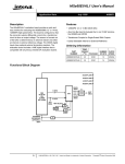
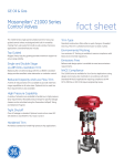
-TABLE
- - OF-CONTENTS--
PLANNING & MOUNTING YOUR SYSTEM
------------------
10
Amplifier's provide high-performance sound reinforcement for you're
mobile audio equipment. The Multi-Mode bridging capabilities allow
flexibility in hosting several different speaker configurations.
To achieve optimum performance, it is highly recommended that you read
this Owners Manual before beginning installation.
FEATURES
- - -
Controls-&- Functions
-
- -
Digital Full range Amplifier
Fully regulated MOSFET power supply
PWM circuitry
2 Ohm stable stereo
Tri-guard amplifier protection
I D I (~intelligent Distresslndicator )gives a visual indication of
the amplifiers protection status
Platinum RCA inputs and outputs
Bi-linear selectable crossover for inputs and outputs (HiIFulllLow)
Continuously variable High pass filter : 50~z-250~fi12dBslopes)
Continuously variable Low pass filter : 50Hz-250Hz (1 2dB slopes)
Subwoofer equalizer control : 0-1 2dB
Input sensitivity : 200mV-8V
Frequency response : 10Hz-20KHz
SIN ratio : 100 dB
OEM floating ground input
Platinum 4-gauge power connectors
Tri-mode operation
SMA2.340 1 2.480 I 2.700 FRONT
Specifications
.-
~
SMA2.700 REAR
Controls-& Functions-
. -
.
-
Controls
-& Functions
..
-~
-
.
BASS
BOOST
I%i\
0
+I268
PWR(Power):This GREEN LED will illuminate when the amplifier is turned "ON". If it fails
to illuminate, check the power connections to the Amplifier and fuses.
BY usina the bass boost function, bass notes at 50Hz are em~hasized
as much as 12dB.
I
JJNE@..
LlNE OUT LlNE IN
CH~,.'"'
CHI
PROT(h0tection):The amplifier protection circuitry will disable the amplifier if input overload.
shod circuit or extremely high temperature conditions are detected. When the protection
mode is in operation, the LED indicator on the side panel will be illuminated, indicating the
amplifier has gone into a self-preservation mode.
.-- LlNEOUT
CHI
If you observe that the Protection LED is lit,please check the system carefully to determine
what has caused the protectionclrcuit to engage. The amplifier can be reset by turning the
remote power off and then on again. If the amplifier shut down due to a thermal overload
condition, please allow it to cool down before restarting. If the amplifier shut down because
of an input overload or short circuit, be sure to repair these conditions before attempting to
power up the amplifier again.
I
These inputs are for signal cables from the source. Always use high quality shielded
RCA cables.
LINE IN
LlNE OUT LlNE IN
CH3
CHI
*! ...+IL~:..
Power
I
Rnmmtn ~ n m a
UNEOUT
.
CHI.."-".
a.
I
I
-Due to the power requirements of the Amplifier, this connection should be made
directly to the positive(+) terminal of battery. For safety measure, install an in-line
fuse Holder (not included) as close to the battery positive(+) terminal as possible with
an ampere rating ; not to exceed total value of fuses in Amp.
The LlNE OUT allows you to build multiple amplifier systems without having to use splitter
cords to distribute the signal. Now it is simply a matter of bringing one set of RCAS into
the first amplifier, then using the line out RCA jacks as the feed to the next amplifier.
I
r
---,
.
m
Power
I
I
I
.......
I
I
Planning and Mounting Your System
-Controls-&-Functions
--- .---
The mounting position of your Amplifier wlll have a great effect on its ability to
dissipate the heat generated during normal operation.
Under normal conditions, the heatsink will dissipate sufficient heat to avoid thermal
shutdown. However please do not install the amplifier in a wooden box or similar
device as this will prevent heat dissipation into the atmosphere.
Power
To avoid unwanted ignition noise caused by ground loops, it is essential that the
Amplifier be grounded to a clean, bare, metal surface of the vehicles chassis.
Note :GROUND WIRE SHOULD NOT BE EXTENDED MORE THAN 3 FT ( I METER).
SPEAKER
CH3
SPEAKER
-
+ CH4
Temperatures in car trunks have been measured as high as (155'F) in the summer
time. since the thermal shut-down point for the amplifier is (158'F) it is easy to
see that it must be mounted for maximum cooling capability. To achieve
maximum advantage of convection air flow in an enclosed trunk, mount the
amplifier in a horizontal position.
Cooling requirements are considerably relaxed when mounting inside the passenger
compartment since the driver will not offen allow temperatures to reach a critical
point. Floor mounting under the seat is usually satisfactory as long as there is at least
1 inch of clearance (2.54 cm) above the Amplifier's fins for. ventilation.
A. Select a suitable location that is convenient for mounting, is accessible for wiring.
And has ample room for air circulation and cooling.
B. Use the amplifier as a template to mark the mounting holes. Remove the Amplifier
and drill holes. Use extreme caution, inspect underneath surface before drilling!
C. Secure the Amplifier using the screws provided.
-
SMA2.340/2.480/2.700
SMA4.680
coo
_ _ _ Shooting
Trouble
_ _ _- -
Tunina on the Am~lifier
The amplifier automatically turns on within a few seconds after remote voltage Is applied.
If your system is set-up so that the headunit provides the remote voltage; then it would
turn on when your stere6 is turned on. Note that there are alternate means of providing
the 12 volt remote control signal, including installing and auxiliary switch.
SYMPTOMS
CHECK
1s the power
LED illuminated?
(NO)
Check all fuses to amplifier.
Be sure Turn-on lead is connected
check signal leads.
Check gain control.
Check TunerIDeck volume level.
Clean contacts on fuse holders.
Is the Diagnostic
LED illuminated?(YES)
Check for speaker short or
amplifier overheating.
AMP NOT
No power to power wire
Repair power wire or connections.
ON
NO power to remote
wire with receiver on
Check connections to radio.
Burnt or broken fuse
Replace fuse
Check Speaker Leads
Inspect for short circult or an
open connection.
Check Audio Leads
Reverse Left and Right RCA inputs
to determine if the problem is
occurring before the amp.
NO SOUND
Adjusting
TheAudio
-- Level
---
As stated previously, it is important to obtain a close match between the source
unit's output voltage and the amplifier's sensitivity or admittance setting.
1. Use a screwdriver to turn GAlN (MIN I MAX) fully counterclockwise to MIN.
2. Turn the auto sound system's volume control to about one-third of its full range.
3. Adjust GAIN (MIN IMAX) to a comfortable listening level.
4. Turn up the auto sound system's volume control until the sound begins to distort.
Then immediately turn the volume down to a point just before where the
distortion began.
Caution : Never turn up the auto sound system's volume control more than
needed to adjust the audio level, more than two thirds of Its maxlmum volume.
5. Adjust GAIN (MIN/ MAX) until the sound is at the maximum level you want the
amplifier to produce.
6. Adjust the auto sound system's volume control to a comfortable listening level.
FREQUENCY RESPONSE
BASS BOOST ON
+20dB
-B
a
NO SOUND
IN ONE
'
AMP TURNING Check Speaker load
impedance
OFF
MEDIUM /
HIGH
VOLUME
+lOdB
ode
PROTECTION
LAMP ON
z
-1OdB
W
IY
-2OdB
-30dB
10
42
100
500
1K
5K
20K
SOK
FREQUENCY (Hz)
NOTE: Raisingthe Bass frequency allows'higher frequencles to reach the bass speakers
while blockinglower frequencies from midrangespeakers. Loweringthe Bass
frequencies allows lower frequencies to reoch the mldrangespeakers while
blockinghigher frequencles from bass speakers.
REMEDY
Be sure proper speaker load
impedance recommendations
are observed.
(If you use an ohmmeter to check
speaker resistance, please
remember that DC resistance and
AC impedance may not be the same.)
Shut down
Turn radio down
Wait for AMP to cool
Speaker wires shorted
Separate speaker wires and
insulate