1
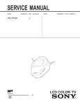
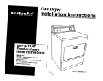
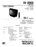
FD-525
SERVICE MANUAL
US Model
FEATURES
SPECIFICATIONS
TV standard
Channel
coverage
American TV standard
VHF channels 2-13
UHF channels 14-69
Radio frequency range
FM 87.6-l 08 MHz
AM 530-l ,710 kHz
VHF/UHF/FM: telescopic antenna
AM: Built-in ferrite bar antenna
4.5-inch
picture measured diagonally
Picture tube
EXT ANT: minijack, 75 ohms
Input
EAR: minijack,
output
impedance 8-300 ohms
Full range 05 cm (02 inches)
Speaker
Power requirements 12 V DC
Battery life
See page 4 for “Power sources.”
Power consumption 10.8 W
Approx. 176.2 x 177x 175.5 mm (w/h/d)
Dimensions
(7 x 7 x 7 inches)
incl. projecting pans and controls
Mass
Approx. 2.8 kg (6 lb 3 oz)
incl. batteries
Supplied accessory AC power adaptor (1)
Antenna
Design and specifications are subject to change without
notice.
Note
Use only recommended AC power adaptor. Do not use
any other AC power adaptor.
Polarity of the plug
l
l
l
l
l
4.5inch black and white 90” deflection picture tube.
The voltage synthesizer tuning system allows easy tuning.
AM/FM tuner is combined.
Built-in e-inch dia. speaker with powerful output and good
sound suitable for garden and kitchen use.
Carrying handle for easy carrying.
SAFETY-RELATED
COMPONENT
WARNING!!
COMPONENTS IDENTIFIED BY MARK A OR DOTTED
LINE WITH MARK A ON THE SCHEMATIC DIAGRAMS
AND IN THE PARTS LIST ARE CRITICAL TO SAFE
OPERATION.
REPLACE THESE COMPONENTS WITH
SONY PARTS WHOSE PART NUMBERS APPEAR AS
SHOWN :lN THIS MANUAL OR IN SUPPLEMENTS PUBLISHED BY SONY.
BLACK AND WHITE
TV-AM/FM TUNER
SONY@
2.
NOTEONTHEANODECAPREMOVAL
Even when the power switch is off, the voltage at the anode
cap is still high.
Remove the anode cap as follows.
1. Discharge the anode pin to the ground.
Pinch and remove the anode pin with a pair of tweezers.
At this time, be careful not to scratch the anode button.
Caution on Reinstallation :
Confirm that the anode button is inserted into the anode cap
securely.
TABLEOFCONTENTS
Section
Section
1. GENERAL
0 Location of Controls. . . . . . . . . . . . . . . . . . . . . . . . . .......
.......
l
Power Sources . . . . . . . . . . . . . . . . . . . . . .
. . . . . . . .......
l Watching the TV . . . . . . . . . . . . . . . . . . . .
.......
l Listening to the Radio . . . . . . . . . . . . . . . .
........
.......
l External Antenna Connection
3. ELECTRICAL ADJUSTMENTS
3-1. Tuner Section . . . . . . . . . . . . . . . . . . . . . . . . . . . . . .
2. DISASSEMBLY
2-1. Cabinet (rear) . . . . . . . . . . . . . . . . . . . .
2-2. A Board . . . . . . . . . . . . . . . . . . . . . . . .
2-3. Cathode-ray Tube . . . . . . . . . . . . . . . .
2-4. R Board . . . . . . . . . . . . . . . . . . . . . . . .
2-5. Pointer Setting . . . . . . . . . . . . . . . . . .
.......
.......
.......
.......
.......
4
4
4
5
5
TV Section . . . . . . . . . . . . . . . . . . . . . . . . . . . . . . . .
....7
....8
4. DIAGRAMS
4.1. Semiconductor Lead Layouts . . . . . . . . . . . . . . .
4-2. Block Diagram . . . . . . . . . . . . . . . . . . . . . . . . . . . . .
4-3. Printed Wiring Boards . . . . . . . . . . . . . . . . . . . . .
4.4. Schematic Diagram . . . . . . . . . . . . . . . . . . . . . . . . .
. ..lO
. . . 11
. . . 13
. . . 15
3-2.
....... 6
....... 6
....... 6
....... 6
....... 6
5. EXPLODED VIEWS
. ..19
5-1. Rear Cabinet Section . . . . . . . . . . . . . . . . . . . . . . .
5-2. Front Cabinet Section . . . . . . . . . . . . . . . . . . . . . . . . 20
6 . ELECTRICAL PARTS LIST . . . . . . . . . . . . . . . . .
-2-
. ..21
SAFETY CHECK-OUT
After correcting the original service problem,
perform the following safety checks before releasing
the set to the customer:
1.
Check the area of your repair for unsoldered or
poorly-soldered connections. Check the entire
board surface for solder splashes and bridges.
2.
Check the interboard wiring to ensure that no
wires are “pinched” or contact high-wattage
resistors.
3.
4.
LEAKAGE
The AC leakage from any exposed metal part to
earth ground and from all exposed metal parts to any
exposed metal part having a return to chassis, must
not exceed 0.5 mA (500 microampers). Leakage
current can be measured by any one of three
methods.
Check that all control knobs, shields, covers,
ground straps, and mounting hardware have
been replaced. Be absolutely certain that you
have replaced all the insulators.
Look for unauthorized replacement parts, particularly transistors, that were installed during a
previous repair. Point them out to the customer
and recommend their replacement.
5.
Look for parts which, though functioning, show
obvious signs of deterioration. Point them out
to the customer and recommend their replacement.
6.
Check the line cord for cracks and abrasion.
Recommend the replacement of any such line
cord to the customer.
I.
Check the condition of the monopole antenna
(if any).
Make sure the end is not broken off, and has
the plastic cap on it. Point out the danger of
impalement on a broken antenna to the
customer,
and recommend the antenna’s
replacement.
Check the B+ and HV to see they are at the
values specified. Make sure your instruments
are accurate; be suspicious of your HV meter
if sets always have low HV.
Check the antenna terminals, metal trim,
“metallized” knobs, screws, and all other
exposed metal parts for AC leakage. Check
leakage as described below.
TEST
1.
A commercial leakage tester, such as the
Simpson 229 or RCA WT-S40A. Follow the
manufacturers’ instructions to use these instruments.
2.
A battery-operated AC milliammeter. The Data
Precision 245 digital multimeter is suitable for
this job.
3.
Measuring the voltage drop across a resistor by
means of a VOM or battery-operated AC voltmeter. The “limit” indication is 0.75V, so
analog meters must have an accurate lowvoltage scale. The Simpson 250 and Sanwa
SH-63Trd are examples of a passive VOM that
is suitable. Nearly all battery operated digital
multimeters that have a 2V AC range are
suitable. (See Fig. A)
HOW TO FIND A GOOD EARTH GROUND
A cold-water pipe is guaranteed earth ground; the
cover-plate retaining screw on most AC outlet boxes is
also at earth ground. If the retaining screw is to be
used as your earth-ground, verify that it is at ground
by measuring the resistance between it and a coldwater pipe with an ohmmeter. The reading should be
zero ohms. If a cold-water pipe is not accessible,
connect a 60-100 watts trouble light (not a neon
lamp) between the hot side of the receptacle and the
retaining screw. Try both slots, if necessary, to locate
the hot side of the line, the lamp should light at
normal brilliance if the screw is at ground potential.
(See Fig. B)
To Exposed Metal
Parts on Set
Trouble Light
Ohmmeter
.
AC
voltmeter
10.75 V)
0.15rF
*
Fig. A.
Earth
Cold-water
Ground
Fig. B.
Using an AC voltmeter to check AC leakage.
-3-
Checking for earth ground.
Pipe
Telescopic
sueen
To indicate the current channel
antenna
POWER swkch
CHANNEL +/- buttons
B R T ( b r i g h t n e s s ) mntrcl
VOLUME control
TV BAND selector (VHFAIHF)
EAR (earphone) jack
CONTR (contrast) ccntml
5
DC IN t2V (external power
i n p u t ) jack
i
RADIO TUNING ~~trcl
CH CALL button
MODE eelector
Dial scale
aattery
comparment (bottom)
Press the CH CALL button.
T h e l i n e a p p e a r s e t t h e p o s i t i o n o f the c u r r e n t c h a n n e l
r---3,6
1
Handle
110 L i s t e n U s i n g t h e E a r p h o n e
CHC :ALL button
2
IEXT A N T ( e x t e r n a l a n t e n n a )
jack
1 Press the POWER switch
2 Se, the MODE selector to TV.
The unit starts
1B a t t e r i e s
Usin on House Current
II 2d AC)
I
MODE
D :6
t . AM
El
4 Select
Size D (R20)
For your safety, do not warch
c o n t r o l s w h i l e drivina.
the N nor operate the
Note
Be sure t o t u r n o f f m e N after use. especially when
l i s t e n i n g w i t h e a r p h o n e . T h i s p r e v e n t s unnecessary
batter/ wear.
the band. VHF or UHF.
x8
4
(P i c t u r e A d j u s t m e n t
5 Tune in the desired channel.
CHANNEL
I
-
>
When to replace batteries
W h e n t h e p i c t u r e became.5
wim new ones.
Use only recommended AC power adaptor. Do not use
any other AC power adaptor.
small, replace all the batteries
3
of the plug
6 A d i u s t t h e a n t e n n a l e n g t h a n d its d i r e c t i o n
7 Adiust the volume.
Battery life
N
Balmtea
I
Polarity
autOmaticallY.
3 Pull cut t h e a n t e n n a f u l l y
Using the supplied AC power adaptor
to DC IN 12V
tunina
I
RAM0
AM PM
Sony SUM-l
PW
1.5
25
25
Sony a l k a l i n e
AM1 (N)
5
70
70
I
V.HOLD control
Turn the control when the picture rolls vertically
To turn off the TV
press
me POWER switch
ad i0id me antenna.
It the channel changes
Note
W h e n m e u n i t i s n o t t o be u s e d f o r a l o n g p e r i o d o f t i m e .
r e m o v e t h e bettedes
to avoid unit damage caused by
ba”ery 1eakaga and ccrrcslon.
If the power is momentarily lost because of a mechanical
s h o c k . o r if t h e u n i t h a s passed t h r o u g h a t u n n e l . t h e
channel may change. If this happens, tune in the desired
channel again with CHANNEL +I-.
BRT Mntrcl
T u r n t h e c o n t r o l c o u n t e r c l o c k w i s e f o r m o r e b r i g h t n e s s end
clcdtwise
lcr l e s s b r i g h t n e s s .
CONTR ccntrcl
T h e p i c t u r e mntrast bewmes s t r o n g e r b y t u r n i n g t h e COntrCl
c o u n t e r c l o c k w i s e . a n d i s r e d u c e d b y t u r n i n g i t ClCckWisB.
1
Outdoor
395
1
antenna
Monitoring the video camera recorder
After connecting as illustrated, turn on the power d the
equipment and tune in the channel 3 or 4.
VHF
antenna
6
4
75ohm
maxtal
cable
1
1 Press the POWER switch.
2 Set the MODE selector to FM or AM.
MODE
3 Pull ail the antenna fully ior FM reception
4 Tune in the desired station
RADIO
TUNING
5 For FM reception. adjust the length and direction of ti?&
Ct”W”M.
For AM reception, rotate the unit.
6 Adjust the volume.
al’
VOLUME
To turn off the radto
Press the POWER switch and told the antenna.
To listen using the earphone
See ‘Watching the TV”.
Note
Se sure to turn oft the radio after we, especially when
listening with earphone. This prevents unnecessary
battery wear.
F-type
COtl”RCtO,
CM)
Antenna cable
(no, Slpplii)
EAC-110
SECTION 2
DISASSEMBLY
Note : Follow the disassembly procedure in the numerical order given.
2-1. CABINET (REAR)
battery case lid
2-3. CATHODE-RAY TUBE
P
Q cabinet (rear)
~BvTP3XlO
C board
\
CRT retainer spring
2-4. R BOARD
0 PTP3XB
OR
2-2. A BOARD
board
2-5. POINTER SETTING
4) Set the pointer bracket.
board
/
pointer to the ditch of
left edge.
0
power button
0 Turn
fully
-6.
PTP3Xb
SECTION 3
ELECTRICAL ADJUSTMENTS
3-1. TUNER SECTION
l
FM Section
FM FREQUENCY COVERAGE
ADJUSTMENT
I
Setting :
MODE switch : FM
I
Adjust for a maximum reading on VTVM.
L3
CT3
86.5MHz
109.5MHz
1
I
FM rf signal
11
generator
antenna
Adjust for a maximum reading on VTVM.
AM FREQUENCY COVERAGE
ADJUSTMENT
deviation by 400Hz signal
output level : as low as possible
Adjust for a maximum reading on VTVM.
l
AM Section
L4
CT4
520kHz
1,750kHz
AM
Setting :
TRACKING
I
ADJUSTMENT
Adjust for a maximum reading on VTVM.
MODE switch : AM
AM rf signal
Ll
CT1
620kHz
1,400kHz
AM IF ADJUSTMENT
Adjust for a maximum reading on VTVM.
Tl
450kHz
30% amplitude
modulation by
400Hz signal
Adjustment Location : R board (component side)
VTVM
(range : 0.5-5V ac)
,
4
EAR j a c k
Repeat the procedures in each adjustment several times,
and the frequency coverage and tracking adjustments
should be finally done by the trimmer capacitors.
l
Remove telescopic antenna in FM section adjustments.
l
I.3
CTJ,
AL-L
FREQFUMENCY
CoYiYGE
-7-
,CTZ
L2-1
::
TR$$ NO
L2-2,
Adjustment Location : A board (component side)
3-2. TV SECTION
Setting :
: TV
MODE switch
TV BAND switch : VHF or UHF
WI01
Centering Adjustment
,
Procedures :
1. Tune in off-the-air signal.
2. Adjust the centering magnet so that the picture is in the
center.
3. After the adjustment, look the magnets with suitable
locking compound.
Adjustment Location :
6+%!v’
ID
WI01
%b”J’”
CRT
El
RV551
V-S I ZE
ADJ
centering magnet
adjustment screw
B+(8.8V) Adjustment
Procedure :
Adjust RV601 for 8.8V reading on collector voltage of Q601.
Horizontal Frequency (H-HOLD) Adjustment
Procedures :
1. Connect between IC201 pin @ and pin @ with lkfi resistor.
2. Connect the frequency counter to IC201 pin 0.
3. Adjust RV501 for a 15.734kHz+60Hz reading on frequency counter.
4. After the adjustment, remove the resistor in item 1.
Vertical Amplitude (V-SIZE) Adjustment
Procedures :
1. Tune in an off-the-air signal.
2. Adjust RV551 for the best vertical amplitude.
RF AGC Adjustment
Procedures :
1. Tune in an off-the-air signal.
2. Adjust RV201 so that snow noise disappears from the
picture.
Tuning Adjustment
Procedures :
1. Short S104 (CH CALL).
(State where the display bar is shown on the screen.)
2. Set S151 (TV BAND) to the VHF side.
3. Receive the broadcast of 2CH by pushing S102 (CHANNEL-) or S103 (CHANNEL+).
4. Adjust RV103 so that the display bar is corresponded to
the position of 2CH.
5. Receive the broadcast of 13CH, and adjust RVlOl so that
the display bar is corresponded to the 13CH.
Note : Since the items 4 and 5 will interfere each other, the
adjustment is necessary for 2 to 3 times.
6. Receive the broadcasts of 2 to 13CH, and check if the
display bar is corresponded to each channel.
7. Set S151 (TV BAND) to the UHF side.
8. Receive the broadcast of 14CH, and adjust RV104 so that
the display bar is corresponded to the position of 14CH.
9. Receive the broadcast of 69CH, and adjust RV102 so that
the display bar is corresponded to the position of 69CH.
Note : Since the items of 8 and 9 will interfere each other,
the adjustment is necessary for 2 to 3 times.
10. Receive the broadcasts of 14CH to 69CH, and check if the
display bar is corresponded to the position of each channel.
11. Disconnect the S104 shorted in the above item 1.
-8-
Adjustment Location : B board (conductor side)
TUNING AOJ
* 1 3 C H G9CH
2CH
14CH’
RVlOl WI02 RV103 R V 1 0 4
n
-9-
SECTION 4
DIAGRAMS
4-1. SEMICONDUCTOR LEAD LAYOUTS
2SB1094mLK
NJM3868S
AN5151N
2SD1159
D
B
e d:
(Top vrnvl
RC78L05A
AN5707NS
2SC2786-K
ITOP VIEW)
CX2011 l-T6
DTC114YS
2SC2785-FEK
GPlOG5020
RL202-Ml1
lOE2
CATHJOE
x
(TOP VIEW)
L5630
DTC144ES
letter ride
AWE
5
RD6.2ES.82
RD7.5ES-B2
lSS119
lSS168
il c a t h o d e
cathode
NJM3404AD
a
7
6
5
2iA952
2SA1175.FEK
2SC2001TP-KlK2
2sc2909
"
anode
RU-3AM
crl
12
(Top
cathode
34
view)
anode
-lO-
SECTION 6
ELECTRICAL PARTS L1S-i
NOTE :
l
Due to standardization, replacements in
the parts list may be different from the
parts specified in the diagrams or the
components used on the set.
l -XX and -X mean standardized parts, so
they may have some difference from the
original one.
l
RESISTORS
All resistors are in ohms.
METAL:Metal-film
resistor.
METAL OXIDE: Metal oxide-film resistor.
F:nonflammable
Ref. No. Part No.
Items marked ‘I*” are not stocked since
they are seldom required for routine service.
Some delay should be anticipated
when ordering these items.
l
SEMICONDUCTORS
In each case, u:~, for example:
uPA..: ,uPA..
uA..: ,uA..
uPB.. : DPB.. U PC.. : L~PC.. uPD..: ,uPD..
l
CAPACITORS
uF: /JF
0 COILS
uH: UH
l
Description
Ref. No. Part No.
Remark
*
A-3016-359-A A BOARD, COMPLETE (INCLUDING B, C BOARD)
****+************
*
l-526-736-00 SOCKET, CRT
7-685-646-79 SCREW +P 3X8 TYPE2 NON-SLIT
< CAPACITOR >
Cl01
Cl02
Cl03
Cl04
Cl05
1-124-464-11
1-162-851-11
l-131-498-00
l-102-074-00
l-102-525-11
ELECT
CERAMIC
TANTALUM
CERAMIC
CERAMIC
0.22uF
0. 1uF
1uF
0. OOluF
68PF
Cl06
Cl07
Cl08
Cl09
Cl10
l-102-121-00
1-101-004-00
1-124-916-11
1-101-004-00
l-102-115-00
CERAMIC
CERAMIC
ELECT
CERAMIC
CERAMIC
2200PF
0. OluF
22uF
0. OluF
560PF
10%
Cl11
Cl14
Cl17
Cl18
Cl20
1-124-927-11 ELECT
l-124-902-00 ELECT
1-101-006-00 CERAMIC
l-102-973-00 CERAMIC
1-101-005-00 CERAMIC
4.7uF
0.47uF
0.047uF
1OOPF
22000PF
20%
20%
Cl21
Cl24
Cl51
Cl52
Cl53
1-124-477-11 ELECT
l-124-902-00 ELECT
l-102-074-00 CERAMIC
l-102-121-00 CERAMIC
l-124-907-11 ELECT
47uF
0.47uF
0. OOluF
2200PF
1OuF
20%
20%
10%
10%
20%
25V
5ov
5ov
5ov
5ov
Cl54
Cl58
Cl59
Cl60
c201
1-101-005-00
l-124-443-00
l-102-074-00
l-102-074-00
1-101-004-00
22000PF
1OOuF
0. OOluF
0. OOluF
0. OluF
20%
10%
10%
5ov
1ov
5ov
5ov
5ov
c202
C203
C205
C206
C207
1-101-004-00 CERAMIC
1-101-004-00 CERAMIC
1-124-916-11 ELECT
l-124-902-00 ELECT
1-101-004-00 CERAMIC
0. OluF
0. OluF
22uF
0.47uF
0. OluF
C208
c209
c210
l-101-880-00 CERAMIC
l-130-473-00 MYLAR
l-123-382-00 ELECT
47PF
0.0015uF
3.3uF
CERAMIC
ELECT
CERAMIC
CERAMIC
CERAMIC
mlslm
20%
10%
10%
5%
20%
10%
5%
20%
20%
5%
5 %
20%
5ov
16V
25V
5ov
5ov
5ov
5ov
63V
5ov
5ov
1oov
5ov
5ov
5ov
5ov
5ov
5ov
63V
5ov
5ov
5ov
5ov
1oov
-21-
Description
l-101-361-00
l-136-161-00
l-124-907-11
l-136-157-00
l-136-157-00
CERAMIC
MYLAR
ELECT
MYLAR
MYLAR
150PF
0.047uF
1OuF
0.022uF
0.022uF
C216 l-102-947-00
C401 l-124-443-00
C402
l-102-116-00
C403
l-102-116-00
C404 l-136-165-00
CERAMIC
ELECT
CERAMIC
CERAMIC
MYLAR
1OPF
1OOuF
680PF
680PF
0. 1uF
5%
20%
10%
10%
10%
5ov
1ov
5ov
5ov
5ov
C405
C406
C407
C408
C451
l-124-907-11
l-101-361-00
l-101-880-00
l-102-121-00
l-136-153-00
ELECT
CERAMIC
CERAMIC
CERAMIC
FILM
1OuF
150PF
47PF
2200PF
0. OluF
20%
5%
5%
10%
5%
5ov
5ov
5ov
5ov
5ov
C452 l-124-120-11
C453 l-136-165-00
C454 1-101-004-00
C455 l-124-360-00
C456 l-124-907-11
ELECT
MYLAR
CERAMIC
ELECT
ELECT
220uF
0. 1uF
0. OluF
1OOOuF
1OuF
20%
10%
25V
5ov
5ov
16V
5ov
C457 1-124-477-11 ELECT
C501 l-136-153-00 FILM
C502 l-130-485-00 MYLAR
C504 1-124-893-11 ELECT
C505
1-101-004-00 CERAMIC
47uF
0. OluF
0.015uF
2200uF
0. OluF
20%
5%
5%
20%
25V
5ov
5ov
1ov
5ov
C506 l-124-903-11 ELECT
C507 l-136-157-00 MYLAR
C508 l-130-479-00 MYLAR
C509 1-126-176-11 ELECT
C551 l-131-347-00 TANTALUM
1uF
0.022uF
0.0047uF
220uF
1uF
20%
10%
5%
20%
10%
5ov
5ov
5ov
1ov
35v
C552
C553
C554
C555
C556
ELECT
TANTALUM
TANTALUM
CERAMIC
ELECT
3.3uF
1uF
1uF
0. OOluF
47uF
20%
10%
10%
10%
20%
1oov
35v
35v
5ov
1ov
ELECT
ELECT
ELECT
ELECT
ELECT
1OOOuF
1OOOuF
47uF
1OOOuF
2200uF
20%
20%
20%
20%
20%
1ov
16V
1ov
1ov
25V
C211
C212
C213
C214
C215
l-323-382-00
l-131-347-00
l-131-347-00
l-102-074-00
l-124-126-00
C557 1-124-473-11
C558 l-124-360-00
C559 l-124-126-00
C560 1-124-473-11
C601 1-124-563-11
20%
20%
Ref. No. Part No.
Description
C602
1-101-005-00 CERAMIC
C603
1-101-004-00 CERAMIC
C604 l-124-907-11 ELECT
0305
1-124-472-11 ELECT
C606 l-124-126-00 ELECT
Remark
22000PF
0. OluF
1OuF
470uF
47uF
CEO1 l-101-005-00 CERAMIC
C802 l-loz-bwoo CERAMIC
C803 l-124-126-00 ELECT
AC804 l-106-379-12 MYLAR
AC805 l-106-379-12 MYLAR
20%
20%
20%
Ref. No. Part No.
5ov
5ov
5ov
1ov
1ov
Description
< FUSE >
AF601 1;532-591-00
FUSE, GLASS TUBE (2A/125V)
< IC >
22000PF ’
0. OOluF
10%
47uF
20%
0.033uF
5%
0.033uF
5%
5ov
5ov
1ov
2oov
2oov
IClOl 8-759-420-88 IC
IC102 8-759-701-50
I C
IC103 8-759-982-21 IC
IC201
l-808-293-11 IC
IC451 8-759-702-01 IC
C806 1-124-915-11 ELECT
C807 1-128-119-21 ELECT
C808
l-102-050-00 CERAMIC
C809 l-136-161-00 MYLAR
C810
1-101-004-00 CERAMIC
1OuF
3.3uF
0. OluF
0.047uF
0. OluF
20%
20%
99%
10%
63V
350v
5oov
5ov
5ov
IC801
C811 1-126-515-11 ELECT
C813 l-106-347-00 MYLAR
C814 l-136-159-00 MYLAR
4.7uF
1500PF
0.033uF
10%
5%
10%
5ov
2oov
5ov
< FILTER >
< CONNECTOR >
1-568-454-11
1-564-777-11
1-564-777-11
1-564-777-11
1-564-778-11
8-759-802-17 IC 15630
< JACK >
5151 l-507-667-00 JACK, MIC (EXT ANT)
5451
1-695-473-11
JACK (EAR)
J601 l-580-288-11 JACK, POWER (DC IN 12V)
< COIL >
1451
1501
1502
PIN. CONNECTOR (PC BOARD) 9P
PLUG, CONNECTOR (2.5MM) 2P
PLUG, CONNECTOR (2.5htM) 2P
PLUG, CONNECTOR (2.5MM) 2P
PLUG, CONNECTOR (2.5MM) 4P
l-408-421-00
l-408-421-00
l-408-418-00
INDUCTOR
INDUCTOR
INDUCTOR
1OOuH
1OOuH
56uH
< TRANSISTOR >
QlOl 8-729-904-36 TRANSISTOR DTCll4YS
QlO2 8-729-119-79 TRANSISTOR 2SC2785-FEK
8151
8-729-119-77 TRANSISTOR
2SA1175-FEK
2SA1175-FEK
4152
8-729-119-77 TRANSISTOR
DTC144ES
8153
8-729-900-89 TRANSISTOR
< DIODE >
Dl
8-719-903-27 DIODE
D2
8-719-903-27 DIODE
DlOl 8-719-911-19 DIODE
D102 8-719-911-19 DIODE
D103 8-719-911-19 DIODE
AN5707NS
NJM3404AD
RC78105A
AN5151N
NJM386BS
1201 l-410-312-11 INDUCTOR
0.22uH
1202 l-404-785-11 COIL, VIF DETECTOR
1203 l-404-785-11 COIL, VIF DETECTOR
1204 l-410-972-11 INDUCTOR
15uH
1402 l-414-030-41 INDUCTOR
27uH
CF201 l-567-115-00 FILTER, CERAMIC
CF202 l-577-066-11 FILTER, CERAMIC (DISCRIMINATOR)
* CN151
CN153
CN451
CN601
* CN801
Remark
lSS168
lSS168
lSS119
lSS119
lSS119
8201
8-729-178-63 TRANSISTOR
8401
8-729-821-01 TRANSISTOR
Q403 8-729-119-79 TRANSISTOR
8451
8-729-904-36 TRANSISTOR
8551
8-729-119-79 TRANSISTOR
D151 8-719-903-27
DIODE lSS168
D152 8-719-911-19 DIODE lSS119
D201 8-719-110-03 DIODE RD7. 5ES-B2
D551 8-719-911-19 DIODE lSS119
D552 8-719-911-19 DIODE lSS119
2SC2786-K
2SC2909
2SC2785-FEK
DTC114YS
2SC2785-FEK
8552
8-729-011-92 TRANSISTOR
2SC2001TP-KlK2
2SA952
8553
8-729-195-23 TRANSISTOR
AQSOl 8-729-141-83 TRANSISTOR 2SB1094-LK
Q602 8-729-119-79 TRANSISTOR 2SC2785-FEK
Q801 8-729-011-92 TRANSISTOR 2SC2001TP-KlK2
D553 8-719-911-19 DIODE lSS119
D601 8-719-979-32 DIODE RL202-Ml1
D602 8-719-109-93 DIODE RD6.2ES-B2
D801 8-719-911-19 DIODE lSS119
D802 8-719-300-33 DIODE RU-3AM
Q802 8-729-017-78
TRANSISTOR 2SD1159
< RESISTOR >
D803 l-808-394-11 DIODE GPlOG5020
D804 8-719-300-33 DIODE RU-3AM
D805 8-719-200-02 DIODE lOE2
R106
R108
-22-
l-249-440-11
1-249-429-11
CARBON
CARBON
82K 5%
10K 5%
l/4!
1/4w
Ref. No. Part No.
Description
Remark
Ref.No. Part No.
Description
Remark
MO9
Ml0
lull
R112
R113
1-249-428-11
1-249-435-11
l-215-459-00
1-249-437-11
1-249-429-11
CARBON
CARBON
METAL
CARBON
CARBON
8.2K
33K
39K
47K
10K
5%
5%
1%
5%
5%
1/4w
1/4w
1/6W
1/4w
1/4w
R401 l-249-409-11 CARBON
R402
1-249-393-11 CARBON
R403
1-249-412-11 CARBON
R404
1-249-417-11 CARBON
R405
1-249-417-11 CARBON
220
5%
10
5%
390
5%
1K
5%
1K
5%
1/4w
1/4w
1/4w
1/4w
1/4w
R115
R116
R117
R118
R120
1-249-426-11
1-249-425-11
1-249-441-11
1-249-437-11
l-215-463-00
CARBON
CARBON
CARBON
CARBON
METAL
5. 6K 5%
4.7K 5%
1OOK 5%
47K 5%
56K 1%
1/4w
1/4w
1/4w
1/4w
1/6W
R406
1-249-429-11 CARBON
R407 1-249-429-11 CARBON
R408
1-249-427-11 CARBON
R409
1-249-413-11 CARBON
R410 l-249-409-11 CARBON
10K
10K
6.8K
470
220
5%
5%
5%
5%
5%
1/4w
1/4w
1/4w
1/4w
1/4w
R121
R122
R123
R124
R125
1-249-417-11
l-249-440-11
1-249-441-11
1-247-899-11
1-249-439-11
CARBON
CARBON
CARBON
CARBON
CARBON
1K
82K
1OOK
680K
68K
5%
5%
5%
5%
5%
1/4w
1/4w
1/4w
1/4w
1/4w
R411
R451
R452
R453
R454
1-249-433-11
1-249-414-11
l-249-401-11
l-249-401-11
1-249-393-11
CARBON
CARBON
CARBON
CARBON
CARBON
22K 5%
560 5 %
47
5%
47
5%
10
5%
1/4w
1/4w
1/4w
1/4w
1/4w
R126
R130
R131
R132
R136
l-249-409-11 CARBON
1-249-417-11 CARBON
l-247-887-00 CARBON
l-247-895-00 CARBON
1-249-437-11 CARBON
220
1K
220K
470K
47K
5%
5%
5%
5%
5%
1/4w
1/4w
1/4w
1/4w
1/4w
R501
R502
R503
R504
R505
l-249-434-11
1-249-433-11
1-249-418-11
1-249-431-11
l-249-405-11
CARBON
CARBON
CARBON
CARBON
CARBON
27K
22K
1.2K
15K
100
5%
5%
5%
5%
5%
1/4w
1/4w
1/4w
1/4w
1/4w
R137
R151
R152
R153
R154
1-249-425-11
1-249-435-11
1-249-429-11
1-249-429-11
1-249-437-11
CARBON
CARBON
CARBON
CARBON
CARBON
4.7K
33K
10K
IOK
47K
5%
5%
5%
5%
5%
1/4w
1/4w
1/4w
1/4w
1/4w
R506
R551
R552
R553
R554
1-249-393-11
1-249-422-11
1-249-418-11
1-249-412-11
1-249-415-11
CARBON
CARBON
CARBON
CARBON
CARBON
10
5%
2.7K 5%
1.2K 5%
390 5 %
680 5 %
1/4w
1/4w
1/4w
1/4w
1/4w
R155
R156
R157
R158
R201
1-249-425-11
1-249-437-11
1-249-425-11
1-249-432-11
1-249-429-11
CARBON
CARBON
CARBON
CARBON
CARBON
4.7K
47K
4.7K
18K
10K
5%
5%
5%
5%
5%
1/4w
1/4w
1/4w
1/4w
1/4w
R555
R556
R557
R558
R559
l-247-889-00
1-249-433-11
1-249-436-11
1-249-426-11
l-249-440-11
CARBON
CARBON
CARBON
CARBON
CARBON
270K 5%
22K 5%
39K 5%
5.6K 5%
82K 5%
1/4w
1/4w
1/4w
1/4w
1/4w
R202
R203
R204
R205
R206
1-249-427-11
1-249-426-11
1-249-413-11
l-249-407-11
l-249-405-11
CARBON
CARBON
CARBON
CARBON
CARBON
6.8K 5%
5.6K 5%
470
5%
150 5 %
100 5 %
1/4w
1/4w
1/4w
1/4w
1/4w
R560
R561
R562
R563
R565
1-249-415-11
1-249-416-11
1-249-411-11
1-249-385-11
1-249-381-11
CARBON
CARBON
CARBON
CARBON
CARBON
680
820
330
2.2
1
5
5
5
5
5
%
%
%
%
%
1/4w
1/4w
1/4w
1/6W
1/4w
R207
R208
R209
R210
R211
1-249-416-11
1-249-429-11
1-249-415-11
l-249-420-11
l-249-409-11
CARBON
CARBON
CARBON
CARBON
CARBON
820
5%
10K 5%
680 5 %
1.8K 5%
220
5%
1/4w
1/4w
1/4w
1/4w
1/4w
R567
R568
R569
R570
R601
1-249-411-11
1-249-433-11
1-249-441-11
1-249-389-11
1-249-416-11
CARBON
CARBON
CARBON
CARBON
CARBON
330
22K
1OOK
4.7
820
5%
5%
5%
5%
5%
1/4w
1/4w
1/4w
1/4w
1/4w
R212
R213
R214
R216
R217
l-249-440-11
1-249-415-11
1-249-421-11
1-249-429-11
1-249-393-11
CARBON
CARBON
CARBON
CARBON
CARBON
82K
680
2.2K
10K
10
5%
5%
5%
5%
5%
1/4w
1/4w
1/4w
1/4w
1/4w
R602
R603
R604
R605
R606
1-249-416-11
1-249-416-11
1-249-416-11
i-249-411-11
i-249-405-11
CARBON
CARBON
CARBON
CARBON
CARBON
820
5%
820
5%
820 ’ 5%
330 5 %
100 5 %
1/4w
1/4w
1/4w
1/4w
1/4w
R218
R219
R220
R221
1-249-423-11
l-249-440-11
l-249-440-11
1-249-429-11
CARBON
CARBON
CARBON
CARBON
3.3K
82K
82K
10K
5%
5%
5%
5%
1/4w
1/4w
1/4w
1/4w
AR607
Ap608
R801
R802
1-249-423-11
1-249-419-11
1-249-417-11
l-249-405-11
CARBON
CARBON
CARBON
CARBON
3.3K
1.5K
1/4w
1/4w
1/4w
1/4w
-23-
5%
5%
5%
100 5%
Ref. No. Part No.
-
Description
Remark
R803 l-249-405-11 CARBON
R804
1-249-429-11 CARBON
R805
1-247-897-11 CARBON
R806
1-247-897-11 CARBON
R807
1-249-433-11 CARBON
100
10K
560K
560K
22K
R808 1-259-882-11 CARBON
R809 1-259-88611 CARBON
R810
1-249-385-11 CARBON
R811 l-247-889-00 CARBON
R812 l-249-436:11
CARBON
3.3M 5%
2.2M 5%
2.2 5%
270K 5%
39K 5%
&4w
1/4w
1/6W
1/4w
1/4w
R813
10K
1/4w
1-249-429-11
CARBON
5%
5%
5%
5%
5%
5%
Ref. No. Part No.
Description
*
A-3016-362-A R BOARD, COMPLETE
**********St*****
1/4w
1/4w
1/4w
1/4w
1/4w
3-714-118-01
4-039-681-01
4-039-691-01
4-039-691-11
4-039-693-01
Remark
SCREW (1.7X4)
GEAR, TUNING
KNOB, RADIO TUNING (BLACK)
KNOB, RADIO TUNING (WHITE)
POINTER
4-039-694-01 DRHM,
TUNING CAPACITOR
4-039-701-01 BRACKET, POINTER
7-685-646-79 SCREW +P 3X8 TYPE2 NON-SLIT
< CAPACITOR >
< VARIABLE RESISTOR >
RVlOl
RV102
RV103
RV104
RV201
RV401
RV451
RV501
RV551
RV552
l-238-020-11 RES, ADJ, CARBON
l-238-020-11 RES, ADJ, CARBON
l-238-019-11 RES. ADJ, CARBON
l-238-019-11 RES, ADJ. CARBON
1-241-629-11 RES, ADJ, CARBON
l-238-049-21
1-223-365-21
l-241-630-11
1-241-628-11
l-238-050-21
RES,
RES,
RES,
RES,
RES,
1OOK
1OOK
47K
47K
4.7K
VAR, CARBON 2K (CONTR)
VAR, CARBON 10K (VOLHME)
ADJ, CARBON 10K
ADJ, CARBON 2.2K
VAIL CARBON 1OOK (Y-HOLD)
ARV601 1-241-627-11 RES. ADJ. CARBON 1K
RV801 l-238-051-21 RES. VAR. CARBON 1M (BRT)
< SWITCH >
SlOl
l-554-088-41 SWITCH, KEY BOARD (CH CALL)
S102 l-554-088-41 SWITCH, KEY BOARD (CHANNEL -1
S103
l-554-088-41 SWITCH, KEY BOARD (CHANNEL +)
S151 l-554-222-00 SWITCH, SLIDE (TV BAND)
S601 1-570-690-U SWITCH, PUSH (POWER)
Cl
c3
c4
c5
C6
l-102-074-00
l-102-960-00
l-102-960-00
l-102-943-00
l-102-973-00
CERAMIC
CERAMIC
CERAMIC
CERAMIC
CERAMIC
0. OOluF
24PF
24PF
6. OPF
1OOPF
10%
5%
5%
0.5PF
5%
5ov
5ov
5ov
50V
5ov
c7
C8
c9
Cl0
Cl1
l-124-907-11 ELECT
l-102-074-00 CERAMIC
l-101-004-00 CERAMIC
l-124-907-11 ELECT
l-124-927-11 ELECT
1OuF
0. OOluF
0. OluF
1OuF
4.7uF
20%
10%
5ov
5ov
5ov
5ov
1oov
Cl2
Cl3
Cl4
Cl5
Cl6
l-124-903-11
l-124-907-11
l-124-907-11
1-101-004-00
l-124-907-11
ELECT
ELECT
ELECT
CERAMIC
ELECT
1uF
1OuF
1OuF
0. OluF
1OuF
20%
20%
20%
20%
5ov
5ov
5ov
5ov
5ov
Cl7
l-124-907-11
ELECT
1OuF
20%
5ov
20%
20%
< FILTER >
CF2
CF3
< FILTER >
1-567-097-61 FILTER, CERAMIC (10.7MHz)
l-567-097-61 FILTER, CERAMIC (10.7MHz)
< CONNECTOR >
SWF201 1-577-244-11 FILTER CERAMIC
* CN152 l-565-980-11 HOUSING,CONNECTOR(PC
BOARD) 9P
< TRANSFORMER >
AT801
< VARIABLE CAPACITOR >
1-439-487-21 TRANSFORMER ASSY, FLYBACK
;;;:;) l-141-458-11 CAP, VAR (RADIO TUNING)
< TUNER >
TH151 1-693-196-11 TUNER U N I T
******t*t*******t********~~****~***********~****~~*~********
< DIODE >
D3
8-719-109-93
DIODE RD6.2ES-B2
< FILTER >
FL1
l-236-022-11 FILTER BAND PASS
The components identified by
mark A or dotted line with mark
A are critical for safety.
Replace only with part number
specified.
-24-
1
R
I
Ref. No. Part No.
Description
Remark
< IC >
ICl
8-752-061-79
I C
Ref. No. Part No.
Description
**t***********************
HARDWARE L 1 ST
*********************LL*****
CX20111-T6
< COIL >
Ll
LZ-1
* 12-z
13
L4
l-402-523-11
l-406-042-00
l-426-074-00
l-422-131-00
l-406-087-11
ANTENNA, FERRITE-ROD (AM)
COIL, FM OSC
COIL, FM RF (A)
COIL, FM OSCILLATION
COIL, OSC (AM)
< RESISTOR >
Ii1
Il.2
R3
R4
R7
1-249-429-11
1-249-421-11
l-249-405-11
1-249-423-11
l-249-409-11
R8
1-249-417-11 CARBON
CARBON
CARBON
CARBON
CARBON
CARBON
10K
2.2K
100
3.3K
220
5%
5%
5%
5%
5%
1/4w
1/4w
1/4w
L/4W
1/4w
1K
5%
1/4w
< SWITCH >
Sl
l-554-061-00 SWITCH, SLIDE (MODE)
< ENCAPSULATED COMPONENT >
Tl
1-236-385-11 ENCAPSULATED COMPONENT
**************t*****+*tt2rr*r*******r*
MISCELLANEOUS
*************
l-546-075-11 CATHODE-RAY TUBE, B/W (E2282)
1-451-365-21 DEFLECTION YOKE
A69
ANT1 l-501-596-11 ANTENNA, TELESCOPIC (BLACK)...(BLACK)
ANT1 l-501-596-21 ANTENNA, TELESCOPIC (WHITE)...(WHITE)
SPl
l-504-247-11 SPEAKER (5CM)
A68
***********************+t*********************************~**
ACCESSORIES & PACKING MATERIALS
*******************************
A
*
*
*
l-467-048-11
3-756-602-21
4-039-803-01
4-039-804-01
4-039-805-01
ADAPTOR, AC (AC-E5251
MANUAL, INSTRUCTION (ENGLISH)
CUSHION (L)
CUSHION (R)
INDIVIDUAL CARTON
-25-
#l
#2
#3
#4
#5
7-685-648-79 SCREW +BVTP 3X12 TYPE2 N-S
7-626-323-31 SPRING PIN 4X14
7-682-548-04 SCREW +B 3X8
7-685-646-79 SCREW +P 3X8 TYPE2 NON-SLIT
7-685-647-79 SCREW, TAPPING, M3XlO
#6
7-685-105-11 SCREW +PTP 2X8
Remark
FD-525
9-957-689-l 1
Sony Corporation
General Audio Group
-26-
English
93co44121
Plinted in Japan
0 1993. 3
Published by Audio Corporate Planning Group