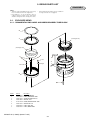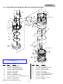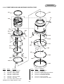
1
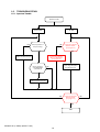
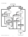
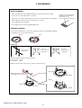
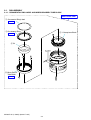
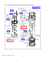
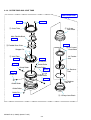
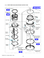
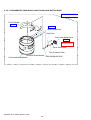
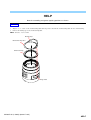
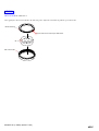
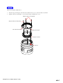
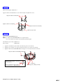
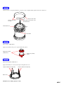
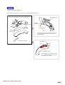
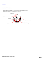
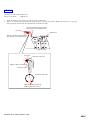
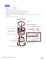
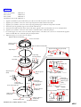
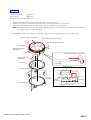
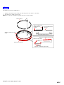
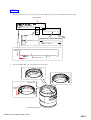
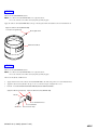
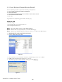
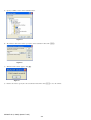
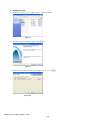
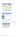
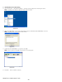
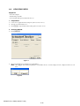
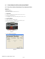
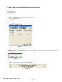
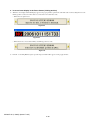
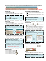
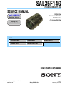
SAL35F14G
(1.4/35G) (35mm F1.4G)
SERVICE MANUAL
US Model
Canadian Model
AEP Model
Chinese Model
Ver 1.1 2007.02
Revision History
How to use
Acrobat Reader
Link
SPECIFICATIONS
DISASSEMBLY
SERVICE NOTE
REPAIR PARTS LIST
ADJUSTMENTS
LENS FOR DSLR CAMERA
SAL35F14G (1.4/35G) (35mm F1.4G)
9-852-108-11
Sony EMCS Co.
2007B0800-1
© 2007.02
Published by Kohda TEC
SPECIFICATIONS
• This lens is equipped with a distance encoder. The distance encoder allows more accurate measurement (ADI) by using a flash for ADI.
• Depending on the lens mechanism, the focal length may change with any change of the shooting distance. The focal length assumes the lens is focused
at infinity.
Equivalent 35mm-format focal length *1 (mm)
52.5
*1 The value for equivalent 35mm-format focal length is based on Digital Single Lens Reflex Cameras equipped with an APS-C sized image sensor.
Lens groups elements
8-10
Angle of view 1 *2
63°
Angle of view 2 *2
44°
*2 The value of angle of view 1 is based on 35mm-format cameras, and that of angle of view 2 is based on Digital Single Lens Reflex Cameras
equipped with an APS-C sized image sensor.
Minimum focus (m (feet)) *3
0.3 (1.0)
*3 Minimum focus is the shortest distance from the image sensor to the subject.
×)
Maximum magnification (×
0.2
Minimum f-stop
f/22
Filter diameter (mm)
55
Dimensions (maximum diameter × height) (mm (in.))
Approx. 69 × 76 (2 3/4 × 3)
Mass (g (oz.))
Approx. 510 (18)
Included items
Lens (1), Front lens cap (1), Rear lens cap (1), Lens hood (1), Carrying case (1), Set of printed documentation
Designs and specifications are subject to change without notice.
SAL35F14G (1.4/35G) (35mm F1.4G)
—2—
TABLE OF CONTENTS
Section
Title
Page
1.
SERVICE NOTE
1-1.
1-2.
1-3.
1-4.
1-5.
Chemicals ······································································· 1-1
Exterior Parts ·································································· 1-1
Unleaded Solder ····························································· 1-1
Safety Check-out ···························································· 1-2
Troubleshooting ····························································· 1-3
2.
DISASSEMBLY
2-1.
Disassembly ··································································· 2-2
3.
REPAIR PARTS LIST
3-1.
3-2.
Exploded Views ······························································ 3-1
Supplied Accessories ······················································ 3-8
4.
ADJUSTMENTS
4-1.
4-2.
4-3.
4-4.
4-5.
Preparations ···································································· 4-1
Aperture Diameter Check/Adjustment ························· 4-13
Projective Resolving Power Check ······························ 4-18
Flange Back (f’F) Check/Adjustment ·························· 4-21
Focus-shift Check/Adjustment (Aperture (Amount of
Spherical Aberration)) ·················································· 4-24
Lens ROM Check ························································· 4-25
Focus Brush Position Check/Adjustment ····················· 4-27
Focus Hold Button Check (Focus Hold Button) ·········· 4-34
Write dSB ····································································· 4-36
4-6.
4-7.
4-8.
4-9.
SAL35F14G (1.4/35G) (35mm F1.4G)
—3—
1. SERVICE NOTE
1-1.
Chemicals
Some chemicals used for servicing are highly volatile.
Their evaporation caused by improper management affects your health and environment, and wastes resources.
Manage the chemicals carefully as follows.
• Store chemicals sealed in a specific place to prevent from exposure to high temperature or direct sunlight.
• Avoid dividing chemicals into excessive numbers of small containers to reduce natural evaporation.
• Keep containers sealed to avoid natural evaporation when chemicals are not in use.
• Avoid using chemicals as much as possible. When using chemicals, divide only required amount to a small plate from the container and
use up it.
1-2.
Exterior Parts
Be careful to the following points for exterior parts used in this unit.
• Use a piece of cleaning paper or cleaning cloth for cleaning exterior parts. Avoid using chemicals.
Even if you have to use chemicals to clean heavy dirt, don’t use paint thinner, ketone, nor alcohol.
• Insert the specific screws vertically to the part when installing a exterior part.
Be careful not to tighten screws too much.
1-3.
Unleaded Solder
This unit uses unleaded solder.
Boards requiring use of unleaded solder are printed with the lead free mark (LF) indicating the solder contains no lead.
(Caution: Some printed circuit boards may not come printed with the lead free mark due to their particular size.)
: LEAD FREE MARK
Be careful to the following points to solder or unsolder.
• Set the soldering iron tip temperature to 350 °C approximately.
If cannot control temperature, solder/unsolder at high temperature for a short time.
Caution: The printed pattern (copper foil) may peel away if the heated tip is applied for too long, so be careful!
Unleaded solder is more viscous (sticky, less prone to flow) than ordinary solder so use caution not to let solder bridges
occur such as on IC pins, etc.
• Be sure to control soldering iron tips used for unleaded solder and those for leaded solder so they are managed separately. Mixing
unleaded solder and leaded solder will cause detachment phenomenon.
SAL35F14G (1.4/35G) (35mm F1.4G)
1-1
1-4.
SAFETY CHECK-OUT
After correcting the original service problem, perform the following safety checks before releasing the set to the customer.
1.
Check the area of your repair for unsoldered or poorly-soldered connections. Check the entire board surface for solder splashes and
2.
bridges.
Check the interboard wiring to ensure that no wires are “pinched” or contact high-wattage resistors.
3.
Look for unauthorized replacement parts, particularly transistors, that were installed during a previous repair. Point them out to the
customer and recommend their replacement.
4.
Look for parts which, through functioning, show obvious signs of deterioration. Point them out to the customer and recommend their
replacement.
5.
6.
Check the B+ voltage to see it is at the values specified.
Flexible Circuit Board Repairing
• Keep the temperature of the soldering iron around 270 °C during repairing.
• Do not touch the soldering iron on the same conductor of the circuit board (within 3 times).
• Be careful not to apply force on the conductor when soldering or unsoldering.
CAUTION
Danger of explosion if battery is incorrectly replaced.
Replace only with the same or equivalent type.
SAFETY-RELATED COMPONENT WARNING!!
ATTENTION AU COMPOSANT AYANT RAPPORT
À LA SÉCURITÉ!
LES COMPOSANTS IDENTIFÉS PAR UNE MARQUE 0 SUR LES
DIAGRAMMES SCHÉMATIQUES ET LA LISTE DES PIÈCES SONT
CRITIQUES POUR LA SÉCURITÉ DE FONCTIONNEMENT. NE
REMPLACER CES COMPOSANTS QUE PAR DES PIÈSES SONY
DONT LES NUMÉROS SONT DONNÉS DANS CE MANUEL OU
DANS LES SUPPÉMENTS PUBLIÉS PAR SONY.
COMPONENTS IDENTIFIED BY MARK 0 OR DOTTED LINE WITH
MARK 0 ON THE SCHEMATIC DIAGRAMS AND IN THE PARTS
LIST ARE CRITICAL TO SAFE OPERATION. REPLACE THESE
COMPONENTS WITH SONY PARTS WHOSE PART NUMBERS
APPEAR AS SHOWN IN THIS MANUAL OR IN SUPPLEMENTS
PUBLISHED BY SONY.
SAL35F14G (1.4/35G) (35mm F1.4G)
1-2
1-5.
TROUBLESHOOTING
1-5-1. Aperture Trouble
Aperture trouble
Function NG
NG
F No. NG
NG
Check operation of
the preset ring.
Perform the aperture
diameter check.
(See page 4-13.)
OK
OK
Perform the aperture
diameter adjustment.
(See page 4-16.)
Replace the defective part.
Check operation
of the diaphragm
control block.
Check operation of the
preset ring, and replace
the defective part.
OK
NG
Replace the defective part.
NG
Perform the aperture
diameter check.
(See page 4-13.)
OK
END
SAL35F14G (1.4/35G) (35mm F1.4G)
1-3
NG
1-5-2. Focus Trouble
Focus trouble
Function NG
Position NG
NG
NG
Check the coupler.
Check the installation of
the main flexible block.
OK
OK
Replace the defective part
or apply the grease.
Reinstall the main
flexible block.
Check the fixed holding
tube and distance
control tube.
OK
NG
NG
Check pattern
of the main flexible block.
OK
Clean the pattern of the
main flexible block.
Replace the defective part
or apply the grease.
Replace the
main flexible block.
NG
Check the operation
again.
OK
Check the foecusing
operation again.
OK
END
SAL35F14G (1.4/35G) (35mm F1.4G)
1-4
NG
2. DISASSEMBLY
NOTE FOR REPAIR
• Make sure that the flat cable and flexible board are not cracked of bent at the terminal.
Do not insert the cable insufficiently nor crookedly.
• When remove a connector, dont’ pull at wire of connector. It is possible that a wire is snapped.
Cut and remove the part of gilt
which comes off at the point.
(Be careful or some
pieces of gilt may be left inside)
• When installing a connector, dont’ press down at wire of connector.
It is possible that a wire is snapped.
• Do not apply excessive load to the gilded flexible board.
UNIVERSAL WRENCH
In case of the following notches or holes are located in the lens block, etc during disassembling/
assembling the lens, Use the universal wrench.
Notches
Holes
How to Use
Chip-A for
universal wrench:
J-6082-609-1
Universal wrench
J-6082-609-A
Chip-B for
universal wrench:
J-6082-609-2
Attach the chip-A or chip-B to the universal wrench.
For the notches: chip-A
For the holes:
chip-B
Match the universal wrench to the holes or notches of the lens block, etc.
Chip-A
Match the universal wrench
to the width of holes or notches.
Universal wrench
Chip-A
Notches
Chip-B
Chip
Chip
Chip-B
Holes
SAL35F14G (1.4/35G) (35mm F1.4G)
2-1
2-1.
DISASSEMBLY
2-1-1. ORNAMENTAL RING LABEL AND MIRROR BARREL TUBE BLOCK
EXPLODED VIEW
1 Ornamental Ring Label
HELP01
2 Ornamental Ring
5 1 Group Lens Block
HELP02
A
3 G1
4 Mirror Barrel
Tube Block
1.4/35G
HELP03
A
SAL35F14G (1.4/35G) (35mm F1.4G)
2-2
2-1-2. LENS MOUNT RIVETING BLOCK AND LIGHT INTER CEPTION TUBE
EXPLODED VIEW
2 Connection Box
!- Orange Ring and
G Ornamental
Ring Block
HELP04
HELP07
HELP04
1 Light Interception
Tube
F
3 Lens Mount
Riveting Block
C
HELP05
SONY
7 Beam
Leather
8 Brush Hole
Cover
A
Preset Ring
Main Spring
HELP06
Preset Ring
Retainer
4 Back Adjustment
Washer
FLANGE BACK (f F)
ADJUSTMENT
B
9 Focus Brush
FOCUS BRUSH
POSITION
ADJUSTMENT
!= Distance Scale
Plate HELP08
D
![ Cam Tube
Reinforcement
6 Coupler and
Coupler Height
Adjustment
Washer
!/ Connector of
DV-FH Flexible
A
HELP09
F
B
5 Ground SP
C
D
E
SAL35F14G (1.4/35G) (35mm F1.4G)
2-3
E
2-1-3. OUTER TUBE AND JOINT TUBE
EXPLODED VIEW
HELP10
HELP10
5 3 Group
Lens Block
1 Outer Tube
Main Flexible Block
HELP11
HELP14
2 Flexible Base Plate
6 Iris Control
Plate Block
Stopper Pin
3 Joint Tube
HELP13
HELP12
Iris Feather
Unit
Guide Pin
HELP13
Guide Roller
Guide Pin
Guide Roller
Guide Roller
HELP13
HELP13
Guide Pin
Guide Pin
Iris Retainer
Tube
Guide Roller
HELP13
Guide Pin
Guide Roller
Iris Retainer
Tube SP
Guide Roller
Guide Pin
4 2 Group Lens Block
HELP13
SAL35F14G (1.4/35G) (35mm F1.4G)
2-4
2-1-4. FIXED TUBE BLOCK AND DISTANCE CONTROL TUBE
EXPLODED VIEW
2 Cam Tube Retainer
HELP15
3 Fixed Tube
Block
6 Friction (SP)
HELP15
7 Torque Ring
Punching
Stopper
Cam Tube
Torque
Ring A
Fixed Tube
C
A
A
C
7 Torque Ring
Punching
Stopper
B
7 Torque Ring
Punching
Stopper
B
Friction
Cloth A
Float Ring
4 Distance Control
Tube and Control
Tube Guide Pin
Scissors
Lever Block
HELP16
Friction Cloth B
HELP18
Torque
Ring B
5 Torque Ring A,
Float Ring,
Scissors Lever Block,
Torque Ring B
HELP17
SAL35F14G (1.4/35G) (35mm F1.4G)
2-5
1 Distance Tube
Rubber Ring
2-1-5. G ORNAMENTAL RING BLOCK AND FOCUS HOLD BUTTON BASE
EXPLODED VIEW
DV-FH Flexible
HELP19
HELP20
Mount Guide Mark
Click Plate
Focus Hold Button Base
HELP21
FOCUS HOLD
BUTTON CHECK
ft
m
SONY
Focus Hold Button
Dust Protection Tape
Distance Scale Window
FHB ADHESION TAPE
G Ornamental Ring Block
SAL35F14G (1.4/35G) (35mm F1.4G)
2-6
2-1-6. 1 GROUP, 2 GROUP AND 3 GROUP LENS BLOCK
EXPLODED VIEW
HELP23
G10 Retainer
G1
G2
G3
G7
G4
1 Group Lens Block
G5
2 Group Lens Block
HELP22
SAL35F14G (1.4/35G) (35mm F1.4G)
2-7
G8 G9 G10
G6
3 Group Lens Block
HELP
Note for assembling and grease applying positions are shown.
HELP01
1.
2.
Align of ”/” of “1.4/35” of the ornamental ring label with range index, and stick the ornamental ring label onto the ornamental ring.
Remove the masking tape of the ornamental ring label.
Note: Tolerance: ±2.5 = ±1 mm
Masking Tape
Ornamental Ring Label
Ornamental Ring
Range Index
SAL35F14G (1.4/35G) (35mm F1.4G)
HELP
HELP02
Adhesive bond (B-10): J-6082-612-A
After applying the adhesive bond (B-10) to the indicated portion, tighten the ornamental ring with the special lens fixture.
Ornamental Ring
Apply the adhesive bond (B-10) in width 10mm.
G1
Mirror Barrel Tube
SAL35F14G (1.4/35G) (35mm F1.4G)
HELP
HELP03
Adhesive bond (B-40): J-6082-614-A
1.
2.
Align the ring positioning pin of the mirror barrel tube block to U groove of the fixed tube, attach them.
Apply the adhesive bond (B-40) to 3 screws shown in figure and tighten the screws.
Apply the adhesive bond (B-40)
Apply the adhesive bond (B-40)
Mirror Barrel Tube Block
Ring Positioning Pin
1 Group Lens Block
U Groove
SAL35F14G (1.4/35G) (35mm F1.4G)
HELP
HELP04
Adhesive bond (B-40): J-6082-614-A
Apply the adhesive bond (B-40) to 5 screws shown in figure and tighten the screws.
Apply the adhesive bond (B-40)
Apply the adhesive bond (B-40)
Apply the adhesive bond (B-40)
Light Interception Tube
HELP05
Adhesive bond (LOCTITE 460) (Note)
Note: Use adhesive bond (LOCTITE 460) or an equivalent article.
Do not use what becomes white after drying like quick-drying glue.
Anti-diffusion agent (A-20): J-6082-611-A
Grease (G-85):
J-6082-626-A
1.
2.
Apply the anti-diffusion agent (A-20) to the indicated portions of lens mount.
Apply the grease (G-85) to 3 locations of indicated portion3 (3 locations) of lens mount.
3.
Apply the adhesive bond (LOCTITE 460) to the stopper screw and attach it to the lens mount.
Apply the adhesive bond (LOCTITE 460)
Apply the grease (G-85) to 3 locations of
indicated portion.
Lens Mount
Apply the anti-diffusion agent (A-20)
to all circumferences of indicated Portion.
Apply the grease (G-85) (rear side)
SAL35F14G (1.4/35G) (35mm F1.4G)
HELP
HELP06
Oil (O-20): J-6082-610-A
Apply small amount of oil (O-20) to the instruction portion of the main spring.
Aplly small amount(O-20)(On contact area)
HELP07
Adhesive bond (B-40):
J-6082-614-A
Anti-diffusion agent (A-20): J-6082-611-A
1.
2.
Apply the anti-diffusion agent (A-20) to the indicated portion of G ornamental ring.
Apply the adhesive bond (B-40) to 4 screws shown in figure and tighten the screws.
3.
Lay out the DV-FH flexible properly.
Apply the adhesive bond (B-40)
Apply the adhesive bond (B-40)
Apply the anti-diffusion agent (A-20) to
all circumferences of indicated portions.
Layout DV-FH Flexible
Connector
G Ornamental Ring Block
Mount Guide
Mark
DV-FH Flexible
G Ornamental Ring Block
Apply the anti-diffusion agent (A-20)
Apply the anti-diffusion agent (A-20) (inside) to
all circumferences of indicated portions.
SAL35F14G (1.4/35G) (35mm F1.4G)
HELP
HELP08
Affix the distance scale plate with distance scale plate set tape, aligning with the punch mark on the cam tube set.
Distance Scale Plate
Distance Scale Plate
Set Tape
Align with the punch mark on the
fixed Tube block.
Fixed Tube Block
Punch Mark
HELP09
Grease (G-85): J-6082-626-A
Apply grease (G-85) to the gear of coupler and the slide portion.
Apply grease (G-85).
(slide portion)
Apply grease (G-85).
(gear)
HELP10
Adhesive bond (B-40): J-6082-614-A
Apply bond (B-40) to 4 screws shown in figure and tighten the screws.
Apply the adhesive bond (B-40)
Apply the adhesive bond (B-40)
Outer Tube
SAL35F14G (1.4/35G) (35mm F1.4G)
HELP
HELP11
Adhesive bond (B-60): J-6082-616-A
Please follow the following points at the time of obtaining a main flexible block.
Main Flexible Block
Part A is bent in the direction of the arrow, and it puts it.
A
Flexible
Base Plate
Flexible Tape B
Sticking standard
Flexible
Base Plate
Flexible tape B is put on the flexible base plate and
after putting, Main flexible block is put along the
putting standard.
Flexible Set Tape D
Flexible Block
A
Flexible base plate
Main Flexible Block is turned in part A, put,
and the adhesive bond (B-60) is spread on
the instruction part in figure.
SAL35F14G (1.4/35G) (35mm F1.4G)
HELP
HELP12
Adhesive bond (B-40): J-6082-614-A
Grease (G-85):
J-6082-626-A
1.
Apply the adhesive bond (B-40) to the tips of screwed portions of 2 stopper pins and tighten 2 stopper pins.
2.
3.
Apply the adhesive bond (B-40) to the tips of 4 screws shown in figure and tighten 4 screws.
Apply the grease (G-85) to all circumferences of gear of joint tube.
Stopper pin
Apply the adhesive bond (B-40)
Stopper pin
Apply the adhesive bond (B-40)
Apply the adhesive bond (B-40)
Apply the grease (G-85)
to the circumference of gear.
SAL35F14G (1.4/35G) (35mm F1.4G)
HELP
HELP13
Adhesive bond (B-40): J-6082-614-A
1.
2.
Rotarting the cam tube, affix indicated hole of the cam tube and U groove of the fixed tube.
Align the notch of the fixed tube and pin of the iris control plate block, attach the inner tube.
3.
Select the guide rollers fitting to the grooves of cam tube set, apply the adhesive bond (B-40) to the tips of screwed portions of guide
pins, and tighten the guide pins.
Note: Confirm that the cam tube rotates smoothly.
Cam Tube
Notch
Fixed Tube
U Groove
Hole
Apply the adhesive
bond (B-40)
Guide Pin
Guide Roller
Guide Pin
Guide Roller
Apply the adhesive
bond (B-40)
Apply the adhesive
bond (B-40)
Apply the adhesive
bond (B-40)
Notch
Guide Pin
Guide Roller
Guide Roller
Guide Pin
Apply the adhesive
bond (B-40)
Guide Roller
Apply the adhesive
bond (B-40)
Guide Pin
Guide Pin
Guide Roller
Pin of iris control plate block
Inner Tube
2 Group Lens Block
SAL35F14G (1.4/35G) (35mm F1.4G)
HELP
HELP14
Anti-diffusion agent (A-20): J-6082-611-A
Adhesive bond (B-10):
J-6082-612-A
1.
Apply anti-diffusion agent (A-20) to the indicated portion of Inner Tube.
2.
After “4-2-2. Aperture Diameter Adjustment”, apply the adhesive bond (B-10) in with of 10mm to all circumferences of portions
indicated in figure at Inner Tube, Iries Retainer Tube and Iris Retainer (SP).
Apply the anti-diffusion agent (A-20) to
all circumference of indicated portion.
Inner tube
G10 Retainer
Apply the anti-diffusion agent (A-20) to
all circumference of indicated portion.
G7
G8 G9 G10
3 group lens block
Inner Tube
Iris Retainer Tube (SP)
Apply the adhesive bond (B-10)
Iris Retainer Tube
Iris Retainer Tube (SP)
Apply the adhesive bond (B-10)
(width of 10mm to 3 locations)
SAL35F14G (1.4/35G) (35mm F1.4G)
HELP
HELP15
Adhesive bond (B-10):
Grease (G-35):
J-6082-612-A
J-6082-621-A
Anti-diffusion agent (A-20): J-6082-611-A
1.
2.
Apply the anti-diffusion agent (A-20) to the indicated portions of cam tube.
Apply the grease (G-35) to the cam tube, cam groove and them contact zone.
3.
4.
Attach the float ring so that the groove of cam tube places the bosses of float ring.
Apply the grease (G-35) to the indicated portions of cam tube retainer.
5.
After tightening the cam tube retainer, loosen it about 10 to 15mm from dead end, apply the adhesive bond (B-10) to indicated
portion.
6.
Comform the movement of the cam tube.
After confirming the movement,
apply the adhesive bond (B-10) in
width of 5 to 10mm to 2 locations.
Cam Tube Retainer
Apply the grease (G-35) to holding
surface sides of cam tube retainer.
Cam Tube
Apply the anti-diffusion agent (A-20)
Apply the anti-diffusion agent (A-20)
Apply the grease (G-35)
(6 locations of cam groove)
Apply the anti-diffusion agent (A-20)
Cam Tube
Cam Tube Apply the grease (G-35)
Apply the grease
Cam Tube Retainer
(G-35)
Groove
Fixed Tube
Apply the grease (G-35)
Boss of float ring
Fixed Tube
Apply the adhesive bond (B-10)
(circumference of 2 locations,
width of 5 to 10mm)
Apply the grease (G-35)
(6 locations of cam groove)
Distance Control Tube
SAL35F14G (1.4/35G) (35mm F1.4G)
HELP
HELP16
Adhesive bond (B-40):
Grease (G-35):
J-6082-614-A
J-6082-621-A
Grease (G-80):
J-6082-625-A
Anti-diffusion agent (A-20): J-6082-611-A
1.
Apply the anti-diffusion agent (A-20) and the grease (G-35) to the indicated portion of the fixed tube.
2.
3.
Apply the grease (G-80) to contact zone of the torque ring B, the fixed tube and the friction (SP).
Apply the grease (G-80) to contact zone of the torque ring punching stopper and the float ring and the fixed tube.
4.
5.
Attach the torque ring punching stopper to the fixed tube with indicated.
Attach the friction (SP) and torque ring A shown in the figure, apply the adhesive bond (B-40) to the screws and tighten them.
6.
7.
Apply the grease (G-80) to contact zone of the distance control tube and the control tube guide pin.
Loosen the stopper screw of the scissors lever block, align the distance control tube to the scissors lever and attach them. Apply the
8.
adhesive bond (B-40) to the control tube guide pin and tighten them.
Tighten the stopper screw of the scissors lever block.
Apply the adhesive bond (B-40)
Scissors lever block
Apply the adhesive
bond (B-40)
Apply the adhesive bond (B-40)
Apply the anti-diffusion agent (A-20)
Torque Ring A
Torque Ring
Punching Stopper
Friction (SP)
long
Fixed Tube
short
Fixed Tube
Torque Ring B
Torque Ring A
Friction (SP)
Apply the grease
(G-35)
Apply the grease
(G-35)
short
Fixed Tube
Apply the grease (G-80)
long
Torque Ring
Punching Stopper
short
long
Torque Ring
Punching Stopper
Control Tube Guide Pin
Torque Ring
Punching Stopper
Groove
Control Tube
Guide Pin
Apply the adhesive
bond (B-40)
Apply the grease
(G-80)
Fixed Tube
Distance Control Tube
Apply the grease (G-80)
Apply the adhesive
bond (B-40)
Distance Control Tube
Apply the adhesive
bond (B-40)
Control Tube Guide Pin
Control Tube
Guide Pin
SAL35F14G (1.4/35G) (35mm F1.4G)
HELP
HELP17
Adhesive bond (B-40):
Grease (G-115):
J-6082-614-A
J-6082-627-A
Anti-diffusion agent (A-20): J-6082-611-A
1.
2.
Apply the anti-diffusion agent (A-20) to the indicated portions of the torque ring A.
Apply the grease (G-115) to contact zone of the torque ring A, the float ring and the scissors lever block.
3.
Attach the float ring and the scissors lever block to the torque ring A, tighten the screw temporarily.
Note: When turning the float ring, to become shake is minimized and to become turn the float ring smoothly, do the adjustment of
the changing wick pin of scissors lever block.
4.
Attach the float ring B to float ring A shown in the figure, apply the adhesive bond (B-40) to the screws and tighten them.
Apply the adhesive bond (B-40)
Apply the anti-diffusion agent (A-20)
Apply the adhesive bond (B-40)
Torque Ring A
Apply the anti-diffusion
agent (A-20)
Apply the anti-diffusion agent (A-20)
Apply the adhesive
bond (B-40)
Float RIng
Torque Ring A
Charging Wick Pin
Torque Ring A
Scissors lever block
Scissors
lever block
Scissors
lever block
Float RIng
Torque Ring B
Apply the grease (G-115)
SAL35F14G (1.4/35G) (35mm F1.4G)
HELP
HELP18
Anti-diffusion agent (A-20): J-6082-611-A
1.
2.
Apply the anti-diffusion agent (A-20) to the indicated portion of the distance control tube.
Affix the friction cloth B shown in figure.
Note: Do not flow the anti-diffusion agent into affix side of friction cloth B.
Friction Cloth B
• Affix to shaded portion.
Standard position
of taping
Do not protrude from the
upper part.
Apply the anti-diffusion agent
(A-20)
Do not float, Do not peel off
Apply the anti-diffusion agent (A-20)
Distance Control Tube
Distance Control Tube
Apply the anti-diffusion agent (A-20)
SAL35F14G (1.4/35G) (35mm F1.4G)
HELP
HELP19
1.
Affix the flexible set tape A, the flexible set tape D and the FHB adhesion tape to the DV-FH flexible shown in figure.
DV-FH Flexible
FHB Adhesive Tape
Flexble Set Tape D
Standard
position
Standard
position
2.
Flexble Set Tape A
Affix the DV-FH flexible to G ornamental block shown in figure.
DV-FH Flexible
Standard
position
G Ornamental Block
SAL35F14G (1.4/35G) (35mm F1.4G)
HELP
HELP20
Adhesive bond (LOCTITE 460) (Note)
Note: Use adhesive bond (LOCTITE 460) or an equivalent article.
Do not use what becomes white after drying like quick-drying glue.
Apply the adhesive bond (LOCTITE 460) to the tip of mount guide mark and install it to the G ornamental block.
Apply the adhesive bond (LOCTITE 460)
to the tip mount guide mark
Mount guide mark
G Ornamental Block
ft
m
HELP21
Adhesive bond (LOCTITE 460) (Note)
Note: Use adhesive bond (LOCTITE 460) or an equivalent article.
Do not use what becomes white after drying like quick-drying glue.
Adhesive bond (B-10): J-6082-612-A
1.
Apply a little amount of the adhesive bond (LOCTITE 460) to the indicated portions of focus hold button base.
2.
3.
Apply the adhesive bond (B-10) to the tip of one screw shown in figure and tighten the screw.
Perform “4-8. FOCUS HOLD BUTTON CHECK (FOCUS HOLD BUTTON)”.
Apply the adhesive bond (B-10)
Apply the adhesive bond (LOCTITE 460)
Washer
Focus Hold Button Base
Focus Hold Button
Click Plate
Dust Protection Tape
SAL35F14G (1.4/35G) (35mm F1.4G)
HELP
HELP22
Anti-diffusion agent (A-20): J-6082-611-A
Apply the anti-diffusion agent (A-20) to all circumferences of indicated portions.
Apply the anti-diffusion agent (A-20) to all
circumference of shaded portion.
Apply the anti-diffusion agent (A-20) to all
circumference of shaded portion.
Large 2 Group Move Frame
G4
G5
G6
2 Group Lens Block
HELP23
Adhesive bond (B-10): J-6082-612-A
After the optical axis adjustment (Refer to 4-22 page), apply the adhesive bond (B-10) to the indicated portion of G10 retainer.
Apply the adhesive bond (B-10)
G10 Retainer
G7
G8 G9 G10
3 Group Lens Block
SAL35F14G (1.4/35G) (35mm F1.4G)
HELP
3. REPAIR PARTS LIST
DISASSEMBLY
NOTE:
• -XX and -X mean standardized parts, so they may
have some difference from the original one.
• Items marked “*” are not stocked since they are
seldom required for routine service. Some delay
should be anticipated when ordering these items.
3-1.
•
The mechanical parts with no reference number in
the exploded views are not supplied.
EXPLODED VIEWS
3-1-1. ORNAMENTAL RING LABEL AND MIRROR BARREL TUBE BLOCK
2
A
1
(See Page 3-6.)
(See Page 3-6.)
4
3
8
3
7
4
4
5
Ref. No.
Part No.
Description
1
2
3
4
5
2-684-732-01
2-887-838-01
2-684-731-01
2-684-730-01
A-1191-451-A
RING, ORNAMENTAL
LABEL, ORNAMENTAL RING
SCREW, TAPPING M1.6X3.5
WASHER, FLAT
BLOCK, MIRROR BARREL TUBE
6
7
8
2-684-737-01 NAME PLATE 3514
2-684-073-01 LABEL, LENS (NO.)
2-695-837-01 LABEL, MODEL NAME
6
SAL35F14G (1.4/35G) (35mm F1.4G)
3-1
1.4/35G
A
DISASSEMBLY
3-1-2. LENS MOUNT RIVETING BLOCK AND LIGHT INTER CEPTION TUBE
51
62
61
52
51
61
62
65
F
53
63
(See Page 3-5.)
51
C
54
54
67
55
SONY
64
65
66
68
56
69
B
A
57
70
71
58
D
59
E
67
60
72
73
(Note 1)
(Note 1)
(See Page 3-3.)
A
74
F
B
C
D
(Note 1)
Ref. No.
The number or type of these parts need to be selected
according to adjustment etc..
Select the part referring to page 3-7.
E
Part No.
Description
Ref. No.
51
52
53
54
55
2-684-064-01
2-684-844-01
2-684-736-01
2-687-685-01
A-1191-450-A
SCREW, M1.4X2.2 P1
CONNECTION BOX
TUBE, LIGHT INTERCEPTION
SCREW, TAPPING M2.0X4.0
BLOCK, LENS MOUNT RIVETING
56
57
58
59
60
2-684-244-01
2-684-856-01
2-684-233-01
2-684-234-01
Selection parts
SCREW, STOPPER
RING, PRESET
SPRING, MAIN
RETAINER, PRESET RING
WASHER (A) to (E), BACK ADJUSTMENT (Note 1)
61
62
2-687-690-01 SCREW, M1.6X3.0
2-684-170-01 SCREW, M1.6X3.0
SAL35F14G (1.4/35G) (35mm F1.4G)
3-2
Part No.
Description
63
64
65
66
67
2-684-961-01
2-684-740-01
2-684-738-01
2-684-739-01
2-684-774-01
RING, ORANGE
LEATHER, BEAM
TAPE, BEAM LEATHER FIXED
COVER, BRUSH HOLE
SCREW, M1.4X2.0 P2
68
69
70
71
72
2-684-786-01
2-684-775-01
2-684-776-01
2-684-773-01
2-684-784-01
BRUSH, FOCUS
PLATE, DISTANCE SCALE
TAPE, DISTANCE SCALE PLATE SET
REINFORCEMENT, CAM TUBE
COUPLER
73
74
Selection Parts WASHER (A) to (E) (Note 1)
2-684-735-01 GROUND SP
DISASSEMBLY
3-1-3. OUTER TUBE AND JOINT TUBE
101
101
(See Page 3-6.)
102
103
101
101
104
106
105
111
101
107
107
101
112
108
113
109
109
110 (Note 1)
110 (Note 1)
(See Page 3-4.)
114
109
110 (Note 1)
109
110
(Note 1)
109
(See Page 3-6.)
110
(Note 1)
110
(Note 1)
109
(Note 1)
Ref. No.
Part No.
Description
101
102
103
104
105
2-687-690-01
2-684-781-01
A-1191-446-A
2-684-841-01
2-684-840-01
SCREW, M1.4 P3 M1.6X3.0
TUBE, OUTER
BLOCK, MAIN FLEXIBLE
TAPE (B), FLEXIBLE
PLATE, FLEXIBLE BASE
106
107
2-684-842-01 TAPE (D), FLEXIBLE SET
2-684-779-01 PIN, STOPPER
Ref. No.
SAL35F14G (1.4/35G) (35mm F1.4G)
3-3
The number or type of these parts need to be selected
according to adjustment etc..
Select the part referring to page 3-7.
Part No.
Description
108
109
110
111
112
2-684-777-01
2-684-749-01
Selection parts
A-1191-444-A
A-1191-443-A
TUBE, JOINT
PIN, GUIDE
ROLLER (A) to (I), GUIDE (Note 1)
BLOCK, IRIS CONTROL PLATE
FEATHER UNIT, IRIS
113
114
2-684-814-01 TUBE, IRIS RETAINER
2-684-815-01 TUBE (SP), IRIS RETAINER
DISASSEMBLY
3-1-4. FIXED TUBE BLOCK AND DISTANCE CONTROL TUBE
151
160
161
152
154
155
155
C
153
A
A
154
161
154
163
155
155
161
C
B
B
162
163
156
163
157
164
164
158
158
158
164
159
165
Ref. No.
Part No.
Description
151
152
153
154
155
2-684-748-01
A-1191-438-A
2-684-802-01
2-684-119-01
2-684-762-01
RETAINER, CAM TUBE
BLOCK, FIXED TUBE
RING (A), TORQUE
SCREW, M1.6X2.5
SCREW, M1.6X2.5
156
157
158
2-684-803-01 CLOTH (A), FRICTION
2-684-804-01 RING, FLOAT
A-1191-440-A BLOCK, SCISSORS LEVER
Ref. No.
SAL35F14G (1.4/35G) (35mm F1.4G)
3-4
Part No.
Description
159
160
161
162
163
2-684-806-01
2-684-745-01
2-684-746-01
2-684-811-01
2-684-747-01
RING (B), TORQUE
FRICTION (SP)
STOPPER, TORQUE RING PUNCHING
TUBE, DISTANCE CONTROL
PIN, CONTROL TUBE GUIDE
164
165
2-684-812-01 CLOTH (B), FRICTION
2-684-741-01 RING, DISTANCE TUBE RUBBER
DISASSEMBLY
3-1-5. G ORNAMENTAL RING BLOCK AND FOCUS HOLD BUTTON BASE
201
202
207
203
209
208
204
ft
m
SONY
205
212 213
211
210
(7.7 x 7 mm)
206
Ref. No.
Part No.
Description
201
202
203
204
205
2-684-847-01
2-684-848-01
2-683-692-01
A-1191-448-A
A-1191-455-A
TAPE (A), FLEXIBLE SET
TAPE (D), FLEXIBLE SET
GUIDE MARK, MOUNT
BLOCK, G ORNAMENTAL RING
WINDOW, DISTANCE SCALE
206
207
2-684-846-01 TAPE, FHB ADHESION
2-684-849-01 FLEXIBLE, DV-FH
Ref. No.
SAL35F14G (1.4/35G) (35mm F1.4G)
3-5
Part No.
Description
208
209
210
211
212
2-684-850-01
2-684-209-01
2-684-208-01
2-689-275-01
2-684-853-01
WASHER, STANDARD
SCREW, M1.4X1.5 P1
PLATE, CLICK
TAPE, DUST PROTECTION
BUTTON, FOCUS HOLD
213
2-684-852-01 BASE, FOCUS HOLD BUTTON
DISASSEMBLY
3-1-6. 1 GROUP, 2 GROUP AND 3 GROUP LENS BLOCK
(Ornamental Ring, See Page 3-1.)
253
255
257
G1
G2
G3
G7
G4
G5
G8 G9 G10
G6
258
251
252
Ref. No.
Part No.
Description
251
252
253
254
255
2-684-879-01
A-1191-451-A
2-684-759-01
A-1191-452-A
2-684-813-01
G1
BLOCK, 1 GROUP LENS
FRAME, LARGE 2 GROUP MOVE
BLOCK, 2 GROUP LENS
TUBE, INNER
256
257
258
A-1191-453-A BLOCK, 3 GROUP LENS
2-684-872-01 RETAINER, G10
2-684-871-01 G10
254
256
SAL35F14G (1.4/35G) (35mm F1.4G)
3-6
3-1-7. SELECTION PARTS
Ref. No.60
These washers are provided for flange back adjustment.
Change the thickness (t) according to result of adjustment.
Part No.
Description
2-684-123-01
2-684-124-01
2-684-125-01
2-684-126-01
2-684-127-01
WASHER (A), BACK ADJUSTMENT (t=0.05mm)
WASHER (B), BACK ADJUSTMENT (t=0.07mm)
WASHER (C), BACK ADJUSTMENT (t=0.1mm)
WASHER (D), BACK ADJUSTMENT (t=0.2mm)
WASHER (E), BACK ADJUSTMENT (t=0.5mm)
Ref. No.73
These washers are provided for coupler height adjustment.
Change the thickness (t) according to result of adjustment.
Part No.
Description
2-684-057-01
2-684-058-01
2-684-059-01
2-684-060-01
2-684-061-01
WASHER (A) (t=0.05mm)
WASHER (B) (t=0.07mm)
WASHER (C) (t=0.1mm)
WASHER (D) (t=0.2mm)
WASHER (E) (t=0.5mm)
Ref. No.110
Select the type of part according to the operation load of the associated parts.
D1
D2
Part No.
Description
2-684-750-01
2-684-751-01
2-684-752-01
2-684-753-01
2-684-754-01
2-684-755-01
2-684-756-01
2-684-757-01
2-684-758-01
ROLLER (A), GUIDE (D1=4.53mm, D2=4.03mm)
ROLLER (B), GUIDE (D1=4.53mm, D2=4.02mm)
ROLLER (C), GUIDE (D1=4.53mm, D2=4.01mm)
ROLLER (D), GUIDE (D1=4.52mm, D2=4.03mm)
ROLLER (E), GUIDE (D1=4.52mm, D2=4.02mm)
ROLLER (F), GUIDE (D1=4.52mm, D2=4.01mm)
ROLLER (G), GUIDE (D1=4.51mm, D2=4.03mm)
ROLLER (H), GUIDE (D1=4.51mm, D2=4.02mm)
ROLLER (I), GUIDE (D1=4.51mm, D2=4.01mm)
SAL35F14G (1.4/35G) (35mm F1.4G)
3-7
3-2.
SUPPLIED ACCESSORIES
Checking supplied accessories.
Other accessories
Lens Hood (SH0001)
2-687-324-01
2-685-162-01 MANUAL, INSTRUCTION
(JAPANESE, ENGLISH, FRENCH, SPANISH)
2-685-162-11 MANUAL, INSTRUCTION
(GERMAN, DUTCH, SWEDISH, ITALIAN) (AEP)
2-685-162-21 MANUAL, INSTRUCTION (PORTUGUESE, RUSSIAN,
TRADITIONAL CHINESE, KOREAN) (AEP)
2-685-162-31 MANUAL, INSTRUCTION
(SIMPLIFIED CHINESE, ARABIC) (AEP, CH)
Front Lens Cap
2-683-616-01
• Abbreviation
CH: chinese model
Rear Lens Cap
2-683-615-01
Carrying Case
2-694-833-01
SAL35F14G (1.4/35G) (35mm F1.4G)
3-8
4. ADJUSTMENTS
Note: After the service repair, perform the adjustments referring to this section.
4-1.
PREPARATIONS
4-1-1. List of Service Tools and Equipments
• Variable Transformer (Output voltage: AC 100 V) (Note 3)
• Camera DSLR-A100
• Compact Flash (CF) Card (For image saving)
• Screen (Art paper)
• Tape Measure
• Plane Mirror (For SLRs)
• Adhesive bond (B-10): J-6082-612-A
• Lens Adjustment Program (ActuatorChecker.exe)
• PC Card Setup File (InstaCal.exe)
• Color Calculator 2
Note: Color Calculator 2 and ActuatorChecker is downloadable from the ESI homepage.
J-1
J-2
USB cord with
connector
1-833-062-11
Personal computer
(Note 1)
J-4
J-3
J-5
J-6
1000 mm Collimator
110V: J-6082-604-A
240V: J-6082-604-B
(Note 2)
AE master lens
J-6082-597-A
J-8
J-7
Flange back tester
J-6082-606-A
Lens test projector
J-6082-605-A
(Note 3)
J-9
60
80
70
A-mount
attachment
J-6082-607-A
90
50
0
40
20
10
30
J-11
J-10
Luminance box
J-6082-581-A
Finished
Inspection
JIG
J-6082-645-A
(Note 4)
Aberration
measuring cap
(SAL35F14G)
J-6082-641-A
Fig.4-1-1
SAL35F14G (1.4/35G) (35mm F1.4G)
4-1
Flange back gauge
(43.50mm)
J-6082-608-A
Note 1:
Personal Computer (PC)
(Color Calculator 2 installed)
OS:
MEMORY:
Windows XP
40 M Byte or more recommended
Hard disk free area: 15 M Byte or more recommended
USB terminal:
Standard equipment
Graphics:
32,000 colors or more recommended VGA monitor
Note 2: Attach the chart to the 1000 mm collimator as shown in Fig. 4-1-2.
Align the marks
Chart
1000 mm collimator
Fig.4-1-2
Note 3: Connect the variable transformer (Output voltage: AC 100 V) to the lens test projector.
Note 4: Finished Inspection JIG is AC 100 V only.
SAL35F14G (1.4/35G) (35mm F1.4G)
4-2
4-1-2. Lens Adjustment Program (ActuatorChecker)
The lens adjustment program is required for the following check/adjustment.
4-5. FOCUS-SHIFT CHECK/ADJUSTMENT (APERTURE)
4-6. LENS ROM CHECK
4-7. FOCUS BRUSH POSITION CHECK/ADJUSTMENT AND PATTERN CHECK
4-8. FOCUS HOLD BUTTON CHECK
4-9. Write dSB
Prepare/start the lens adjustment program with the following steps.
Equipment used
• Personal Computer
• Lens Adjustment Program (ActuatorChecker.exe)
• PC Card Setup File (InstaCal.exe)
Note 1: Lap top PC with PC card slot on which Windows XP runs
Note 2: Obtain the PC card setup file (InstaCal.exe) from the ESI homepage.
Note 3: Obtain the lens adjustment program (ActuatorChecker Ver. x.x.x.x.zip) from the ESI homepage.
1. Download of PC card setup file (InstaCal.exe)
1)
Create the “MCC”folder in the C drive.
Fig.4-1-3
2)
Download the file from Service Fixture and Software of ESI homepage, and save it in “C:\MCC”.
3)
4)
Double-click the downloaded file “InstaCal.exe”to extract it.
The window to specify the extract destination folder appears. Click [Browse...].
Fig.4-1-4
SAL35F14G (1.4/35G) (35mm F1.4G)
4-3
5)
Specify “C:\MCC” for the extract destination folder.
Fig.4-1-5
6)
The window returns to the menu to specify the extract destination folder. Click [Unzip].
Fig.4-1-6
7)
When the window below appears, click [OK].
Fig.4-1-7
8)
Return to the menu to specify the extract destination folder. Then, click [Close] to close the window.
SAL35F14G (1.4/35G) (35mm F1.4G)
4-4
2. Setup of PC Card
1)
Double-click “InstaCal.exe” in “C:\MCC” folder to begin the installation.
Fig.4-1-8
2)
The menu to begin the installation appears. Click [Next>].
Fig.4-1-9
3)
Specify the install destination folder. As the default is used for it, click [Next>].
Fig.4-1-10
SAL35F14G (1.4/35G) (35mm F1.4G)
4-5
4)
The menu to tell that the wizard is ready to install appears. Click [Install].
Fig.4-1-11
5)
The installation is completed. Click [Finish].
Note: To refer to the “readme” file, check the “Show the readme file” and click [Finish].
Fig.4-1-12
6)
To make the configuration installed effective, the window to prompt the restart appears.
Click “Yes” to restart the PC.
Note: If a device is connected without restarting, the program may not work properly.
Fig.4-1-13
SAL35F14G (1.4/35G) (35mm F1.4G)
4-6
7)
8)
After restarting the PC, insert the PC-CARD-DIO48 in the PC card slot.
The software installation window appears.
Click “Install the software automatically. (Recommended)”.
Fig.4-1-14
9)
The software is detected and installed. When the window below appears, click [Finish] to terminate the installation.
Fig.4-1-15
SAL35F14G (1.4/35G) (35mm F1.4G)
4-7
3. Confirmation of PC card setting
1)
Select “All programs” - “MeasumentComputing” - “InstaCal” from the startup menu, and start up the software.
Note: Depending on the Windows setting, the window below may differ.
Fig.4-1-16
2)
When “PC-CARD-DIO48” is detected, the window below appears. Confirm that the PC-CARD-DIO48” is checked.
Note: Depending on the slot inserted, the slot No. differs.
Fig.4-1-17
3)
Confirm that “PC-CARD-DIO48” is recognized as “Board#0”.
Note: If not recognized as “Board#0”, the program does not work properly.
Fig.4-1-18
4)
Click “File” - “Exit” to terminate “InstaCal”.
SAL35F14G (1.4/35G) (35mm F1.4G)
4-8
4. Startup of Lens Adjustment Program (ActuatorChecker.exe)
1)
Download the file “ActuatorChecker VerX.X.X.X.zip” from Service Fixture and Software of ESI homepage, save and extract it.
2)
3)
Start up “ActuatorChecker.exe” from an arbitrary folder.
If “PC-CARD-DIO48” is properly installed, the window below appears.
Note: The version of “ActuatorCheker” might be updated.
Fig.4-1-19
SAL35F14G (1.4/35G) (35mm F1.4G)
4-9
4-1-3. Connection of Finished Inspection JIG and Lens Adjustment Program
(ActuatorChecker.exe)
Note: Confirm “4-1-2. Lens Adjustment Program (ActuatorChecker)” has been completed before this procedure is executed.
Equipment
• Personal Computer
• USB cord with connector
• Finished Inspection JIG
• Lens Adjustment Program (ActuatorChecker.exe)
1.
Connect equipment and checking lens as shown Fig.4-1-20.
Finished Inspection JIG
Lens
Fig.4-1-20
2.
3.
Turn on the finished inspection JIG.
Turn on the personal computer.
4.
Start up “ActuatorChecker.exe” from an arbitrary folder, conform that start up program normally.
Note: Turn off the finished inspection jig after use.
SAL35F14G (1.4/35G) (35mm F1.4G)
4-10
4-1-4. Initial Setting of “ActuatorChecker”
1.
Start up “ActuatorChecker.exe”.
Fig.4-1-21
2.
Depending on the initial startup or setting made at the previous startup, the window differs.When the English window appears, click
the [Set up] button.
Note: When any button is clicked, the Serial window appears. The window to enter the lens serial number appears.
Fig.4-1-22
SAL35F14G (1.4/35G) (35mm F1.4G)
4-11
3.
Set the following contents in the SETUP window.
• MODEL
Model to be adjustment this time
• Language
• State
4.
English
FINAL
• PROCESS
SERVICE
Confirm that all of the items are set, and click [OK].
Fig.4-1-23
4-1-5. About Inspection Procedure of Lens Adjustment Program (ActuatorChecker)
The inspection method has the method of executing the method of inspecting the corresponding model as everything continues and the
inspection of each item one by one.
Click [START] from the start up window when you inspect the corresponding model as everything continues.
The procedure for executing the inspection of each item one by one has been described in this manual.
SAL35F14G (1.4/35G) (35mm F1.4G)
4-12
4-2.
APERTURE DIAMETER CHECK/ADJUSTMENT
4-2-1. Aperture Diameter Check
Equipment
• Luminance Box
• Camera DSLR-A100
• AE Master Lens
• Compact Flash (CF) Card (For image saving)
• Personal Computer (PC)
(Color Calculator 2 installed)
1. Preparations
1)
Install the CF card to the camera.
2)
Set the equipments, camera and master lens as shown in Fig.4-2-1.
Shoot the center of the luminance surface
Luminance box
Luminance: EV11
Camera
ISO: 100
Exposure Mode: M
Shutter Speed: 1/125
Aperture: F5.6
Focus Mode: MF
Metering: Center weighted
Preset white balance: Tungsten
D-R: OFF
Master lens or checking lens
Focus: Infinity end
Fig.4-2-1
3)
Shoot the images under the following conditions and save them.
Note: Shoot the center of the luminance surface three times with the master lens and checking lens.
Setting of Luminance box:
Luminance:
Setting of Lens:
EV11
Focus:
Setting of Camera:
Infinity end
ISO:
Exposure Mode:
100
M
shutter Speed:
Aperture:
1/125
F5.6
Focus Mode:
Metering:
MF
Center weighted
Preset white balance: Tungsten
D-R:
OFF
SAL35F14G (1.4/35G) (35mm F1.4G)
4-13
2. Checking of Image
Note: Check the image of both master lens and checking lens.
1)
Start the Color Calculator 2.
Fig.4-2-2
2)
Read the image from the file menu.
k
Fig.4-2-3
3)
Set the Color Calculator 2 as follows.
Measured value display (Display menu): RGB+L*a*b*
Measuring method (Display menu):
Center Single Area
Fig.4-2-4
Color space (Edit menu): sRGB
Fig.4-2-5
Area size for calculate (Edit menu →Option): 256×256 Pixels
Fig.4-2-6
SAL35F14G (1.4/35G) (35mm F1.4G)
4-14
4)
5)
Click the calculate button to measure the image.
After measuring, check the “G” values.
Average “G” value of the three images shoot with master lens: (a)
Average “G” value of the three images shoot with checking lens: (b)
Calculate button
Check the “G” value
Fig.4-2-7
3. Checking Method
1)
Calculate aperture error using the following formula, and check that the aperture error is within the specification.
Aperture error = Average “G” value of master lens (a) - Average “G” value of checking lens (b)
Specification
Aperture error = 0 ±12
2)
When the aperture error is out of specification, perform “4-2-2. Aperture Diameter Adjustment”.
SAL35F14G (1.4/35G) (35mm F1.4G)
4-15
4-2-2. Aperture Diameter Adjustment
Equipment
• Luminance Box
• Camera DSLR-A100
• AE Master Lens
• Compact Flash (CF) Card (For image saving)
• Personal Computer (PC)
(Color Calculator 2 installed)
• Adhesive bond (B-10)
1. Preparations
1)
2)
Disassemble up to the group lens block.
Assemble the lens mount (including the preset ring).
Lens Mount
Fixed Tube Block
Fig.4-2-8
3)
Remove the adhesive bond fixing the iris retainer tube (SP).
Apply bond(B-10) (3 areas)
Iris Retainer Tube
Bond
Bond
Iris Retainer Tube SP
Fig.4-2-9
SAL35F14G (1.4/35G) (35mm F1.4G)
4-16
2. Adjusting Method
1)
Move the preset ring and fix it at the fully opened position.
Set the preset ring at the open aperture position.
Preset lever
Fig.4-2-10
2)
Adjust by rotating the iris retainer ring so that the blades of iris are just hidden within the inner diameter of iris retainer ring.
Diaphragm blades are hidden into the
edge completely.
Fig.4-2-11
3)
4)
After adjustment, apply the adhesive bond (B-10) to portions shown in Fig.4-2-9.
Assemble the lens in the state of near completion. Perform “4-2-1. Confirmation of iris diameter”.
Note: Repeat “4-2-2. Adjustment of iris diameter” and “4-2-1. Confirmation of iris diameter” until the iris tolerance meets the specification.
SAL35F14G (1.4/35G) (35mm F1.4G)
4-17
Ver 1.1 2007.02
4-3.
PROJECTIVE RESOLVING POWER CHECK
Equipment
• Lens Test Projector and Variable Transformer (Output voltage: AC 100 V)
Note: Connect the variable transformer (Output voltage: AC 100 V) to the lens test projector.
• A-mount Attachment
• Screen (Art paper)
• Tape Measure
• Plane Mirror (For SLRs)
1. Preparations
Note: Check the projective resolving power of the checking lens at the following focal-length and distance.
Focal-length
f (mm)
Distance (m)
35
1.4
Table 4-3-1
1)
Perform the following steps (1) to (3), and incorporate the internal lenses of the lens test projector according to the checking focallength.
(1) Open the lid of the lens test projector.
(2) Pull up and turn the fixed levers on the right and left sides of the lens test projector.
(3) Remove or insert the lens.
Note: Be sure to have the right position and direction of the lens.
Incorporate of the lenses
according to the checking focal-length (f).
Lens
Fixed lever
Heat-absorbing filter
Chart
Chart
Filament
f=18 to 35 mm
Filament
f=100 to 200 mm
Fixed lever
Lid
Chart
Chart
Filament
f=35 to 100 mm
Lens test projector
Fig.4-3-1
SAL35F14G (1.4/35G) (35mm F1.4G)
4-18
Filament
f=200 to 300 mm
2)
3)
Attach the checking lens to the lens test projector, and set the equipments as shown in Fig.4-3-2.
Turn the fan switch of the lens test projector to ON, then turn the lamp switch to ON.
Screen
A-mount attachment
Checking lens
Fan switch
Chart
Plane mirror
F
L
Lamp switch
Lens test projector
Distance
Fig.4-3-2
4)
5)
Turn the focus ring of the checking lens until the chart image projected on the screen is the sharpest at the center (y’=0).
Set the plane mirror to the center of the projected image (y’= 0), and adjust the projector position so that the mirror reflects the light
to the center of the lens.
SAL35F14G (1.4/35G) (35mm F1.4G)
4-19
Ver 1.1 2007.02
2. Checking Method
1)
Turn the focus ring of the checking lens until the chart image projected on the screen is the sharpest at the center (y’=0).
2)
Read the number of the smallest pitched lines at the center (y’= 0).
The number represents for lines per mm.
Saggital (S)
Meridional (M)
Fig.4-3-3
3)
Turn the mount rotation ring of lens test projector until the projected image at a certain peripheral point (y’= 15) on the screen
appears the most unsharp.
Read the number of the smallest pitched lines (both saggital and meridional: 3 lines) at the peripheral point.
Note: When reading the number of the smallest pitched lines, be careful of the spurious resolution.
Spurious resolution is the reversed image of 2 or 4 lines which appears on screen when focus is beyond maximum revolving
power.
Do not confuse spurious resolution for the smallest pitched lines.
Correct resolution
Spurious resolution
Fig.4-3-4
4)
Check that the all readings (y’= 0, saggital (S) and meridional (M) at y’= 15) is within the specification of the Table 4-3-2.
Specification
Number of the smallest pitched lines
Distance (m)
1.4
Center (y’= 0)
(Lines per mm)
125 or greater
Peripheral (y’= 15)
(Lines per mm)
S
M
50 or greater
40 or greater
Table 4-3-2
5)
After the checking is completed, turn the lamp switch of the lens test projector to OFF and cool the inside of the lens test projector,
then turn the fan switch to OFF.
SAL35F14G (1.4/35G) (35mm F1.4G)
4-20
4-4.
FLANGE BACK (f’F) CHECK/ADJUSTMENT
4-4-1. Flange Back (f’F) Check
Equipment
• 1000 mm Collimator
• Flange Back Tester
• A-mount Attachment
• Flange Back Gauge (43.50mm)
1. Preparations
1)
Set the equipments as shown in the Fig.4-4-1.
flange back gauge (43.50mm)
A-mount attachment
Dial Gauge (Min. scale: 0.01 mm)
Objective lens (10x)
Eyepiece ring
Eyepiece lens (7x)
Scale ring
Fig.4-4-1
2)
3)
Looking through the eyepiece lens, turn the eyepiece ring of the flange back tester so that cross line or scale in the view is the sharpest.
Attach the flange back gauge (43.50mm) securely to the A-mount attachment and hold them together.
4)
Turn the focusing knob of the flange back tester so that fine scratches on the flange back gauge (43.50mm) is the sharpest.
Note: Turn the knob in the direction of the arrow of Fig.4-4-2 for correct reading.
Always turn the knob in the arrow
direction for correct reading.
Focusing knob
Focus on fine lines on the surface.
Fig.4-4-2
5)
Turn the scale ring of the dial gauge until the long pointer indicates “0”.
Note: This position is the flange back (f’F) = 43.5 mm.
Memorize the position of short-pointer.
SAL35F14G (1.4/35G) (35mm F1.4G)
4-21
2. Frange Back (f’F) Check
1)
Attach the checking lens to the flange back tester, and set the 1000 mm collimator.
Checking lens
1000 mm collimator
Fig.4-4-3
2)
Set the focus ring of the checking lens to infinity end position while looking through the microscope, and align the optical axis to the
3)
center of the chart image accurately.
Turn the focusing knob of the tester until the chart image is the sharpest (red and green color areas are equal on the chart *).
*: Position in which the color of collimator chart changes from green into red and come into focus.
Also check the optical axis aligns with the chart center. (Refer to Fig.4-4-4.)
Note: Figure shows example. The cause depends on individual lens.
Incorrect aligned
e.g. As the focusing knob is turned, the chart may appear blurry as illustrated.
The cause depends on individual lens.
Optical Alignment
Best alignment
Fig.4-4-4
Optical Axis Adjustment
1)
2)
Turn the G10, or do the adjustment of looseness. After align the axis.
Apply the adhesive bond (B-10) to the G10 retainer.
Note: Tolerance: 0.02 mm or less
3. Checking Method
1)
Calculate the flange back (f’F) of the checking lens using the following formula, and check that the specification of the Table 4-4-1 is
satisfied.
Flange back (f’F) of the checking lens = (SR flange back gauge) + (Number of short-pointer revolution) + (Reading of long-pointer)
Specification
Focal-length
f (mm)
f’F (mm)
(Infinity position)
35
44.58 to 44.60
Table 4-4-1
2)
When the flange back (f’F) of the checking lens is out of specification of the Table 4-4-1, perform “4-4-2. Flange Back (f’F)
Adjustment”.
SAL35F14G (1.4/35G) (35mm F1.4G)
4-22
4-4-2. Over Infinity (Infinity End) Flange Back (f’F) Adjustment
Equipment
•
•
•
•
•
1000 mm Collimator
Flange Back Tester
A-mount Attachment
Flange Back Gauge (43.50mm)
Adhesive bond (B-10)
Adjusting Method
1)
Perform “4-4-1. Confirmation of flange-back (f’F)” and confirm that the flange-back value (f’F) of lens does not meet the specification in Table 4-4-1.
2)
3)
Adjust the lens focus to the infinite.
Observing the microscope, adjust the focus by turning the knob of flange-back measuring equipment.
4)
Calculate the shift amount by formula below.
Shift Amount (x) = f’F (measured value) at infinite - 44.59mm
x: Shift amount to be adjusted by backwasher
5)
Depending on the result in step 4), adjust the thickness of backwasher. (Refer to Table 4-4-2.)
Note: Measure the thickness of backwasher with micrometer or calipers.
• When the shift amount (x) is the positive (+) value: Increase the thickness of backwasher by a value of x.
• When the shift amount (x) is the negative (-) value: Decrease the thickness of backwasher by a value of x.
6)
Build in the backwasher and perform “4-4-1. Confirmation of flange-back (f’F)” again.
Specification
Focal-length
f(mm)
f’F (mm)
(Infinity position)
35
44.58 to 44.60
Table 4-4-2
7)
When the flange back (f’F) is out of specification of the Table 4-4-2, repeat steps 2) to 6) again.
Part No.
Description
2-684-123-01
2-684-124-01
2-684-125-01
2-684-126-01
2-684-127-01
WASHER (A), BACK ADJUSTMENT (t=0.05mm)
WASHER (B), BACK ADJUSTMENT (t=0.07mm)
WASHER (C), BACK ADJUSTMENT (t=0.1mm)
WASHER (D), BACK ADJUSTMENT (t=0.2mm)
WASHER (E), BACK ADJUSTMENT (t=0.5mm)
SAL35F14G (1.4/35G) (35mm F1.4G)
4-23
4-5.
FOCUS-SHIFT CHECK/ADJUSTMENT (APERTURE (AMOUNT OF SPHERICAL
ABERRATION))
This section describes the check/adjustment of focus-shift amount resulting change of focal-length by aperture setting.
Equipment
• 1000 mm Collimator
• Flange Back Tester
• A-mount Attachment
• Flange Back Gauge (43.50mm)
• Aberration measuring cap 55mm (SAL35F14G)
1. Preparations
1)
Perform “1. Preparations” of “4-4-1. Flange Back (f’F) Check”.
2)
Set the checking lens focus to the infinite.
2. Checking Method
1)
Set the lens aperture to the open aperture position, and measure the flange back (f’F).
2)
Set the aberration measuring cap 55mm (F8 equivalent) on the tip of lens as shown in the Fig.4-5-1, then measure the flange back
(f’F).
Aberration measuring cap 55mm (SAL35F14G)
Fig.4-5-1
3)
Calculate amount of focus-shift using the following formula, and check that the specification is satisfied.
Note: The focus-shift amount of the checking lens is difference between the flange back (f’F) of open aperture and flange back
(f’F) reading (using aberration measuring cap 55mm).
Focus-shift = flange back (f’F) of open aperture reading - Flange back (f’F) reading (using aberration measuring cap 55mm)
Specification
Focus-shift (mm) = 0 to +0.15
4)
Perform the “4-9. WRITE dSB”.
SAL35F14G (1.4/35G) (35mm F1.4G)
4-24
4-6.
LENS ROM CHECK
Equipment
• Personal Computer
• Finished Inspection JIG
• Lens Adjustment Program (ActuatorChecker.exe)
1. Preparations
1)
Connected to equipment with checking lens. (Refer to Section 4-1-3.)
2)
3)
Start up of “ActuatorChecker.exe”.
Click [Set up], and perform the initial setting. (Refer to Section 4-1-4.)
2. Checking Method
1) Click [ROM Data].
Fig.4-6-1
2)
The Serial window appears. Input the lens serial number.
Note: When [OK] is clicked without inputting the serial number, the date executed is displayed on the completion window of each
item.
Fig.4-6-2
SAL35F14G (1.4/35G) (35mm F1.4G)
4-25
3)
The message “Move FOCUS to Infinity position. Then push [ENTER].” is displayed on the pop-up window.
Set the focus to the infinity position and press down the ENTER key.
Fig.4-6-3
4)
When “OK” is displayed on the pop-up window, press the ENTER key to return to the initial window.
Fig.4-6-4
3. In case of error display in the ROM Data
1)
When the error display and the NG display appear to the pop up window, press the ENTER key to return to the initial window, and
perform “2. Checking Method” again.
Fig.4-6-5
Fig.4-6-6
2)
Although the lens is positioned at the infinity position, if the “NG” appears, confirm or perform the following.
• 4-7-1. FOCUS BRUSH POSITION CHECK(Search Focus Adjustment Point)
• Cleaning of flexible pattern or the brush.
• Replaceing the brush.
• Replaceing the main flexible unit.
3)
Perform “2. Checking Method” again, repeat the inspection until “OK” appears on the pop-up window.
SAL35F14G (1.4/35G) (35mm F1.4G)
4-26
4-7.
FOCUS BRUSH POSITION CHECK/ADJUSTMENT
4-7-1. Focus Brush Position Check (Search Focus Adjustment Point)
Equipment
• Personal Computer
• Finished Inspection JIG
• Lens Adjustment Program (ActuatorChecker.exe)
1. Preparations
1)
Connected to equipment with checking lens. (Refer to Section 4-1-3.)
2)
3)
Start up of “ActuatorChecker.exe”.
Click [Set up], and perform the initial setting. (Refer to Section 4-1-4.)
2. Checking Method
1)
2)
Set the focus position to infinity position.
Remove the beam leather, confirm that can see the brush base plate.
3)
Loosen two screws fixing the brush base plate.
Screw Screw
Brush Base Plate
Fig.4-7-1
4)
Click the [Search Focus Adj Point].
Fig.4-7-2
SAL35F14G (1.4/35G) (35mm F1.4G)
4-27
5)
The message “If Focus-Adjustment-Point is found, Buzzer sounds”. is displayed on the pop-up window.
Search the position where the sound beeps by turning the lens to the infinity position.
Fig.4-7-3
6)
7)
At the position where the sound beeps, tighten two screws loosened, apply the adhesive bond (B-10) to the screws.
Perform “4-7-2. Focus Brush Position Check” and “4-7-3. Focus Brush Pattern Check”
3. In case of error display in the Search Focus Adjustment Point
1)
When the error display and the NG display appear to the pop-up window, press the ENTER key to return to the initial window, and
perform “2. Checking Method”again.
Fig.4-7-4
Fig.4-7-5
2)
If the “NG” appears again, thought cause communication error of the finished inspection JIG and checking lens, confirm or perform
the following.
• Improper connection of connector.
• Improper of BL contact.
• Disconnection of mirror box fixture.
SAL35F14G (1.4/35G) (35mm F1.4G)
4-28
4-7-2. Focus Brush Position Check (Focus Adjustment Point)
Equipment
• Personal Computer
• Finished Inspection JIG
• Lens Adjustment Program (ActuatorChecker.exe)
1. Preparations
1)
2)
Connected to equipment with checking lens. (Refer to Section 4-1-3.)
Start up of “ActuatorChecker.exe”.
3)
Click [Set up], and perform the initial setting. (Refer to Section 4-1-4.)
2. Checking Method
1) Click the [Focus Adjustment Point].
Fig.4-7-6
2)
The Serial window appears. Input the lens serial number.
Note: When [OK] is clicked without inputting the serial number, the date executed is displayed on the completion window of each
item.
Fig.4-7-7
3)
The message “Move FOCUS to Near position. Then push [ENTER].” is displayed on the pop-up window.
Set the focus to the near position and press down the ENTER key.
Fig.4-7-8
SAL35F14G (1.4/35G) (35mm F1.4G)
4-29
4)
When the Near position check finishes normally, the message “Move FOCUS to Infinity position. Then push [ENTER].” is displayed
on the pop-up window.
Set the focus to the infinity position and press down the ENTER key.
Fig.4-7-9
5)
When the infinity position check finishes normally, “OK” is displayed on the pop-up window, and press the ENTER key to return to
the initial window.
Fig.4-7-10
3. In case of error display in the Focus Adjustment Point
1)
When the error display and the NG display appear to the pop up window, press the ENTER key to return to the initial window, and
perform “2. Checking Method”again.
• In case of error at the near position in the Focus Adjustment Point
Fig.4-7-11
Fig.4-7-12
• In case of error at the infinity position in the Focus Adjustment Point
Fig.4-7-13
Fig.4-7-14
2)
Although the lens is positioned at the near position or the infinity position, if “NG” appears, confirm or perform the following.
• 4-7-1. Focus Brush Position Check (Search Focus Adjustment Point)
• Cleaning of flexible pattern or the brush.
• Replaceing the brush.
3)
Perform “2. Checking Method”again, repeat the inspection until “OK” appears on the pop-up window.
SAL35F14G (1.4/35G) (35mm F1.4G)
4-30
4-7-3. Focus Brush Pattern Check(Focus Brush Pattern)
Equipment
• Personal Computer
• Finished Inspection JIG
• Lens Adjustment Program (ActuatorChecker.exe)
1. Preparations
1)
2)
Connected to equipment with checking lens. (Refer to Section 4-1-3.)
Start up of “ActuatorChecker.exe”.
3)
Click [Set up], and perform the initial setting. (Refer to Section 4-1-4.)
2. Checking Method
1) Click the [Focus Pattern].
Fig.4-7-15
2)
The Serial window appears. Input the lens serial number.
Note: When [OK] is clicked without inputting the serial number, the date executed is displayed on the completion window of each
item.
Fig.4-7-16
3)
The message “Move FOCUS to Near position. Then push [ENTER].” is displayed on the pop-up window.
Set the focus to the near position and press down the ENTER key.
Fig.4-7-17
SAL35F14G (1.4/35G) (35mm F1.4G)
4-31
4)
When the Near position check finishes normally, the message “Move FOCUS to Infinity position at about 5sec.” is displayed on the
pop-up window.
Set the focus to the infinity position and press down the ENTER key.
Fig.4-7-18
5)
When the infinity position check finishes normally, “OK” is displayed on the pop-up window, and press the ENTER key to return to
the initial window.
Fig.4-7-19
3. In case of error display in the Focus Pattern (near position)
1)
When the error display and the NG display appear to the pop-up window, press the ENTER key to return to the initial window, and
perform “2. Checking Method”again.
Fig.4-7-20
Fig.4-7-21
2)
Although the lens is positioned at the near position, if “NG” appears, confirm or perform the following.
• 4-7-1. Focus Brush Position Check (Search Focus Adjustment Point)
• Cleaning of flexible pattern or the brush.
• Replaceing the brush.
• Rotating operation error of the focus ring (rotation speed is not suitable at a regulated speed.).
3)
Perform “2. Checking Method”again, repeat the inspection until “OK” appears on the pop-up window.
SAL35F14G (1.4/35G) (35mm F1.4G)
4-32
4. In case of error display in the Focus Pattern (infinity position)
1)
When the error display and the NG display appear to the pop-up window, perform the work with caution so that setting the lens to the
infinity position can be done in more than 5 seconds and no more than 20 seconds.
• When the focus pattern error
Fig.4-7-22
Fig.4-7-23
• When the lens does not reach the infinity end infinity position seconds.
Fig.4-7-24
2)
Perform “2. Checking Method”again, repeat the inspection until “OK” appears on the pop-up window.
SAL35F14G (1.4/35G) (35mm F1.4G)
4-33
4-8.
FOCUS HOLD BUTTON CHECK (FOCUS HOLD BUTTON)
Equipment
• Personal Computer
• Finished Inspection JIG
• Lens Adjustment Program (ActuatorChecker.exe)
1. Preparations
1)
Connected to equipment with checking lens. (Refer to Section 4-1-3.)
2)
3)
Start up of “ActuatorChecker.exe”.
Click [Set up], and perform the initial setting. (Refer to Section 4-1-4.)
2. Checking Method
1) Click the [Focus Hold Button].
Fig.4-8-1
2)
The Serial window appears. Input the lens serial number.
Note: When [OK] is clicked without inputting the serial number, the date executed is displayed on the completion window of each
item.
Fig.4-8-2
3)
The message “Push [FOCUS HOLD] button once softly.” is displayed on the pop-up window.
Press the focus hold button.
Fig.4-8-3
4)
When the focus hold button check finishes normally, “OK” is displayed on the pop-up window.
Fig.4-8-4
SAL35F14G (1.4/35G) (35mm F1.4G)
4-34
3. In case of error display in the Focus Hold Button
1)
When the Focus Hold Button cannot be pressed within a certain period of time or the button is defective, the window below appears.
Fig.4-8-5
2)
In case of error caused by time-out of key pressing, perform the work with caution so as to press the focus hold button within a
certain period of time.
3)
Although the button is pressed within a certain period of time, if the error occurs, replace parts relating to the focus hold button.
(Refer to “2-1-5. G ORNAMENTAL RING BLOCK AND FOCUS HOLD BUTTON BASE”)
4)
Perform “2. Checking Method”again, repeat the inspection until “OK” appears on the pop-up window.
SAL35F14G (1.4/35G) (35mm F1.4G)
4-35
4-9.
WRITE dSB
Equipment
• Personal Computer
• Finished Inspection JIG
• Lens Adjustment Program (ActuatorChecker.exe)
1. Preparations
1)
Connected to equipment with checking lens. (Refer to Section 4-1-3.)
2)
3)
Start up of “ActuatorChecker.exe”.
Click [Set up], and perform the initial setting. (Refer to Section 4-1-4.)
2. Checking Method
1) Click the [Write dSB].
Fig.4-9-1
2)
The Serial window appears. Input the lens serial number.
Note: When [OK] is clicked without inputting the serial number, the date executed is displayed on the completion window of each item.
Fig.4-9-2
3)
The “Select dsb” window appears.
4)
Being based on the image point shift amount calculated by “4-5. FOCUS-SHIFT CHECK/ADJUSTMENT (APERTURE (AMOUNT
OF SPHERICAL ABERRATION))”, select the button.
Fig.4-9-3
5)
When the Write dSB finishes normally, “OK” appears on the pop-up window.
Fig.4-9-4
SAL35F14G (1.4/35G) (35mm F1.4G)
4-36
3. In case of error in the Write dSB
1)
When the error display and the NG display appear to the pop-up window, press the ENTER key to return to the initial window.
Fig.4-9-5
Fig.4-9-6
2)
If the “NG” appears again, confirm or perform the following.
• Replaceing the main flexible unit.
• Connected state of equipment (Improper connection of BL error.).
3)
Perform “2. Checking Method”again, repeat the inspection until “OK” appears on the pop-up window.
SAL35F14G (1.4/35G) (35mm F1.4G)
4-37
[Description of main button functions on toolbar of the Adobe Acrobat Reader Ver5.0 (for Windows)]
Toolbar
Printing a text
Reversing the screens displayed once
1. Click the Print button
.
2. Specify a printer, print range, number of copies, and other options, and then click [OK].
• To reverse the previous screens (operation) one by one, click
.
the
• To advance the reversed screens (operation) one by one, click
the
.
Application of printing:
To set a range to be printed within a page, select the graphic
and drag on the page to enclose a range to
selection tool
be printed, and then click the Print button.
Application to the Service Manual:
This function allows you to go and back between circuit diagram and printed circuit board diagram, and accordingly it
will be convenient for the voltage check.
Finding a text
1. Click the Find button
.
2. Enter a character string to be found into a text box, and click
the [Find]. (Specify the find options as necessary)
Application to the Service Manual:
To execute “find” from current page toward the previous pages,
select the check box “Find Backward” and then click the
“Find”.
Moving with link
1. Select either palm tool
, zoom tool
, text selection tool
, or graphic selection tool
.
2. Place the pointer in the position in a text where the link exists
(such as a button on cover and the table of contents page, or
blue characters on the removal flowchart page or drawing page),
and the pointer will change to the forefinger form
.
3. Then, click the link. (You will go to the link destination.)
Moving with bookmark:
3. Open the find dialog box again, and click the [Find Again] and
you can find the matched character strings displayed next.
(Character strings entered previously are displayed as they are
in the text box.)
Click an item (text) on the bookmark pallet, and you can move
can display the
to the link destination. Also, clicking
hidden items.
(To go back to original state, click
)
Application to the Service Manual:
The parts on the drawing pages (block diagrams, circuit diagrams, printed circuit boards) and parts list pages in a text
can be found using this find function. For example, find a
Ref. No. of IC on the block diagram, and click the [Find Again]
continuously, so that you can move to the Ref. No. of IC on
the circuit diagram or printed circuit board diagram successively.
Note: The find function may not be applied to the Service
Manual depending on the date of issue.
Zooming or rotating the screen display
“Zoom in/out”
• Click the triangle button in the zoom control box to select the
display magnification. Or, you may click
ing in or out.
or
for zoom-
Switching a page
• To move to the first page, click the
.
• To move to the last page, click the
.
• To move to the previous page, click the
• To move to the next page, click the
.
.
“Rotate”
• Click rotate tool
, and the page then rotates 90 degrees each.
Application to the Service Manual:
The printed circuit board diagram you see now can be changed
to the same direction as the set.
Reverse
985210812.pdf
Revision History
Ver.
Date
History
1.0
2006.10
Official Release
1.1
2007.02
Correction-1
(C1)
SAL35F14G (1.4/35G) (35mm F1.4G)
Contents
—
• Correction of Section 4-3
S.M Correction : Page 4-18, 4-20
S.M. Rev.
issued
—
Yes