1
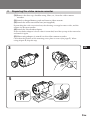
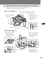
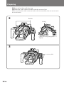
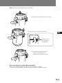
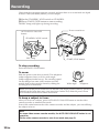
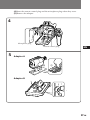
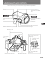
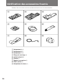
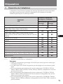
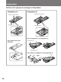
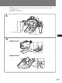
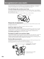
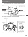
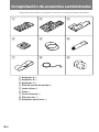
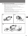
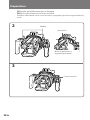
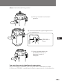
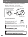
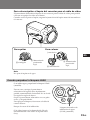
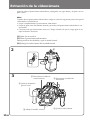
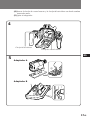
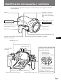
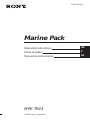
3-862-538-11 (1)
Marine Pack
Operating Instructions
EN
Mode d’emploi
F
Manual de instrucciones
ES
MPK-TRV3
©1998 by Sony Corporation
WARNING
For the Customers in the U.S.A.
This equipment has been tested and found to comply with the limits for a Class B digital device, pursuant to
Part 15 of the FCC Rules. These limits are designed to provide reasonable protection against harmful
interference in a residential installation. This equipment generates, uses, and can radiate radio frequency energy
and, if not installed and used in accordance with the instructions, may cause harmful interference to radio
communications. However, there is no guarantee that interference will not occur in a particular installation. If
this equipment does cause harmful interference to radio or television reception, which can be determined by
turning the equipment off and on, the user is encouraged to try to correct the interference by one or more of the
following measures:
– Reorient or relocate the receiving antenna.
– Increase the separation between the equipment and receiver.
– Connect the equipment into an outlet on a circuit different from that to which the receiver is connected.
– Consult the dealer or an experienced radio/TV technician for help.
You are cautioned that any changes or modifications not expressly approved in this manual could void your
authority to operate this equipment.
Owner’s Record
The model and serial number are located on the inside of the front shell. Record the serial number in the space
provided below.
Refer to these numbers whenever you call upon your Sony dealer regarding this product.
Model No MPK-TRV3
Serial No. ____________________
Table of contents
Features ................................................................................................................................................. 3
Precautions ........................................................................................................................................... 4
Checking supplied accessories .......................................................................................................... 6
Preparing .............................................................................................................................................. 7
1 Preparing the adaptor ............................................................................................................. 7
2 Preparing the video camera recorder ................................................................................... 9
3 Attaching the video camera recorder to the marine pack ................................................. 11
Recording ............................................................................................................................................ 14
When the LEAK lamp flashes ................................................................................................... 15
Removing the video camera recorder ............................................................................................ 16
Note on O-ring ................................................................................................................................... 18
Underwater recording ...................................................................................................................... 20
Labeling parts and controls .............................................................................................................. 21
Specifications ...................................................................................................................................... 22
2-EN
Features
• The MPK-TRV3 marine pack allows the following 8 mm video camera recorders to be used
underwater.
CCD- TR44/TR54/TR57*/TR64/TR66/TR67*/TR74/TR78/TR84/TR86*/TR87*/TR88/TR94/
TR96*/TR98/TR99/TR200*/TR300*/TR500*/TR514/TR555*/TR614/TR710*/TR714/
TR814/TR910*/TR916*/TR917*/TR930*/TR940*/TR2300*/TR3000*/TR3300*/TR3400*
TRV11/TRV12/TRV15*/TRV21/TRV22/TRV25*/TRV30/TRV32*/TRV33/TRV40/TRV41*/
TRV52*/TRV53*/TRV62*/TRV65*/TRV70/TRV72*/TRV75*/TRV81*/TRV82*/TRV85*/
TRV93*/TRV95*/TRV99*/TRV101*/TRV112/TRV212/TRV215*/TRV312*/TRV512*/
TRV615*/TRV715*/TRV815*
• Recording at a depth of 246 feet (75 meters) is possible.
• The following operation can be performed underwater.
– Power on/off
– Auto focusing on/off (models marked with *)
– Recording start/stop
– Power zooming
We recommend you use a wide-conversion lens (not supplied) when using the marine pack.
EN
F
This mark indicates that this product is a genuine accessory for Sony video
products. When purchasing Sony video products, Sony recommends that you
purchase accessories with this “GENUINE VIDEO ACCESSORIES” mark.
ES
3-EN
Precautions
On the video camera recorder
Take care not to expose the equipment to salty air. Do not drip water on the equipment.
• Do not open the marine pack while at sea or at the seaside. Preparations such as
installing and checking the equipment should be made in a place with low humidity
and no salty air.
• When a video camera recorder is used near the sea for a long time, we recommend
that it is checked periodically by a Sony dealer.
• If the equipment becomes wet, take it immediately to the nearest Sony dealer for
preventive maintenance.
On the video camera recorder power source
We recommend that you use battery packs with a large capacity. However, in some
cases battery packs NP-99/4500/F930/F950 cannot be attached to the video camera
recorder.
On the marine pack
• If you open and join the front and rear shells in a place with high temperature and
high humidity, moisture condensation may occur when you put the marine pack in
the water, causing the front glass to fog.
• The waterproof integrity of the marine pack is maintained by the O-ring, and the
groove and surface where it touches. Be especially careful not to damage or deform
that area. For details, see “Note on the O-ring” (page 18).
• Do not leave the marine pack under direct sunlight for a long period of time,
otherwise the temperature in the marine pack may rise and the equipment inside
may be damaged. If you cannot avoid leaving the marine pack under direct sunlight,
be sure to cover the marine pack with a towel or other protection.
• Do not throw the marine pack into the water. Lower it gently into the water.
• Whenever you pick up the marine pack, handle the grip. If the underwater video
light (not supplied) is attached to the marine pack, do not handle the underwater
video light’s arm.
On recording underwater
• Check that the equipment operates correctly and there is no water leak at a depth of
about 3 feet (one meter) before you dive deeper.
• Be sure to follow the safety rules for diving, such as diving period and depth.
• Remove the bubbles from the outside of the front glass.
Sony does not accept liability for damage to the video camera recorder, battery, etc. in
the marine pack or for the loss of prerecorded material if water leak caused by
incorrect operation occurs.
4-EN
On maintenance
After recording in the sea, submerge the marine pack with the buckles tightly fastened
in fresh water for a while to remove the sea water. Then rinse it with fresh water and
wipe it with a soft cloth.
• Every time you use the marine pack and the video camera recorder underwater,
clean the video camera recorder and the inside of the marine pack with a dry soft
cloth. Do not use any type of solvent, such as alcohol or benzine for cleaning, as this
may damage the finish.
• If water comes between the rear shell and the rubber part, remove the rubber and
clean it with a dry soft cloth.
EN
When you store the marine pack
• Coat the O-ring slightly with the supplied grease, and put it in the groove correctly.
Join the front and rear shells then put in a cool place without fastening the buckles.
• Prevent dust from collecting on the O-ring.
• Avoid storing the marine pack in a cold, very hot or humid place, or together with
naphthalene or camphor, as these conditions might damage the unit.
F
ES
On transportation
• When transporting the marine pack, be sure to remove the video camera recorder
from the marine pack.
• When transporting the marine pack by air or by car, use a marine pack carrying case
(not supplied).
5-EN
Checking supplied accessories
Check that the following accessories are supplied with your marine pack.
1
2
3
4
5
6
7
8
9
1 Adaptor A (1)
2 Adaptor B (1)
3 Adaptor C (1)
4 Mounting screw plate (1)
5 O-rings (2)
6 Grease (1)
7 Accessory belt (1)
8 Color filter (1)
9 Viewfinder adaptor (1)
6-EN
Preparing
1
Preparing the adaptor
The adaptor and the position of the mounting screw plate depend on the video camera
model. See the following page when attaching the adaptor and mounting screw plate.
Check the position for the video camera recorder you use.
Position of the mounting screw
plate on the adaptor
Video camera recorder CCDWithout a wide- With a wideconversion lens conversion lens
TRV30/TRV40/TRV70
A1
TR44/TR54/TR64/TR66/TR74/TR78/TR84/TR88/TR94/
TR98/TR99/TR514/TR614/TR714/TR814
A2
A3
TR200/TR300/TR500
B1
B3
TR86/TR96/TR916/TRV11/TRV12/TRV21/TRV22/
TRV32/TRV33/TRV52/TRV53/TRV112/TRV212/TRV312/
TRV512
B2
B5
TRV62/TRV72/TRV82
B2
B9
TR3000
B3
B6
TR555
B3
B7
TRV101
B3
—
TR710/TR910
TR2300/TR3300/TR3400/TRV41/TRV81
B4
B4
B6
B7
TR930
B5
B8
TR57/TR67/TR87/TR917/TR940/TRV15/TRV25/TRV65/
TRV75/TRV85/TRV93/TRV215/TRV615/TRV715/TRV815
B5
B12
TRV95/TRV99
B8
B9
EN
F
ES
A, B —— adaptor to be used.
1, 2, 3… — corresponding number on the adaptor.
Notes
• You should use the wide conversion lens VCL-0637H (not supplied) for the CCDTRV95/TRV99 video camera recorder.
• The CCD-TRV101 video camera recorder cannot be fitted with a wide conversion
lens.
• When you attach a wide conversion lens to the CCD-TRV11/TRV12/TRV21/TRV22/
TRV33/TRV41/TRV81/TRV112/TRV212 video camera recorders, you cannot attach
the viewfinder adaptor.
• When you attach a wide conversion lens to the CCD-TRV11/TRV12/TRV21/TRV22/
TRV33/TRV112/TRV212 video camera recorders, you cannot attach Sony battery
NP-99/4500.
• When you attach a wide conversion lens to the CCD-TR2300/TR3300/TR3400/
TRV95/TRV99 video camera recorders, you cannot attach Sony battery NP-F930/
F950.
7-EN
Preparing
Attaching the mounting screw plate to the adaptor
Adaptor A
Adaptor B
Mounting screw plate
Mounting screw plate
Adaptor A
Adaptor B
Attach adaptor C to adaptor B.
To disassemble after using
Adaptor C
1
2
Adaptor B
To detach adaptor C from adaptor B
3
2
1
8-EN
2
Preparing the video camera recorder
(1) Remove the lens cap, shoulder strap, filter, etc., from the video camera
recorder.
(2) Attach a charged battery pack and insert a video cassette.
(3) Attach the wide conversion lens (not supplied).
By attaching the wide conversion lens, the shooting coverage becomes wider, and the
subject size becomes smaller.
(4) Attach the Viewfinder adaptor.
If the viewfinder adaptor is loose when it is attached, bend the eyecup of the camcorder
and attach it again.
(5) When using adaptor A, attach it to the video camera recorder.
Check that the position of the mounting screw plate is correct (See pages 7). When
using adaptor B, skip this step.
3
4
EN
F
ES
5
1
2
9-EN
Preparing
(6) Adjust the video camera recorder.
Refer to the operation manual of your video camera recorder.
1 Set the POWER
switch to
CAMERA.
L
2 Set the STANDBY
switch to
STANDBY.
K
OC
CAMERA
S
TA
ND BY
The following adjustments are needed when your video camera recorder has the
corresponding function.
Refer to the operation manual of the video camera recorder for details.
White balance
Normally set to w (outdoor).
Set to e (indoor) for night diving.
Shutter speed
Set where no indicator appears.
Program AE
Set where no indicator appears.
Brightness
Turn off the indicator.
Notes
• On some video camera recorder models, you cannot adjust the focus with the button
on the marine pack.
Set the focus to auto focus mode (see page 3).
• When the viewfinder adaptor is attached to the viewfinder of your video camera
recorder, you get a wide view of what appears in the viewfinder screen.
However, the view may be destorted depending on the viewing angle.
10-EN
3
Attaching the video camera recorder to the marine pack
(1) Attach the video camera recorder to the marine pack.
Check the position of the adaptor (See page 7).
When using adaptor A
1 Connect the microphone cable to MIC.
(The sound is recorded in monaural.)
2 Slide the video
camera recorder into
the marine pack until
the hooks of the
camera mount catch
the adaptor.
3 Connect the remote
control cable to l
REMOTE.
4 Fasten the screw.
EN
F
Screwdriver
ES
Camera mount
When using adaptor B
1 Align the right side of
the adaptor with the
hooks of the camera
mount, then push down
the adaptor.
3 Connect the microphone
cable to MIC jack of the
video camera recorder.
(The sound is recorded
in monaural.)
4 Attach the video camera
recorder to the adaptor.
2 Fasten the screw.
5 Connect the remote
control cable to the
l REMOTE jack of the
video camera recorder.
11-EN
Preparing
(2) Raise the buckles until they stop.
(3) Fasten the video camera recorder with the accessory belt.
When you fasten the video camera recorder with accessory belt, take care not to touch
the zoom button.
2
Buckles
O-ring
Check the O-ring and grease it
slightly.
3
Accessory belt
12-EN
(4) Attach the front shell to the rear shell.
1 Put the front shell on the rear shell.
2 Press the top of both grips frimy.
EN
F
Align here as
shown in the
illustration.
ES
3 Lower both buckles at the
same time until they are
locked. You will hear a click.
Now you ready for underwater recording.
Set the STANDBY/LOCK switch of the marine pack to LOCK.
If you set it to STANDBY, the battery may be used up before recording.
13-EN
Recording
Check that the equipment operates correctly and that there is no water leak at a depth
of about 3 feet (one meter) before you dive deeper.
(1) Set the STANDBY/LOCK switch to STANDBY.
(2) Press START/STOP button to start recording.
The REC lamp (red) lights up during recording.
Power zoom lever
AUTO FOCUS ON/OFF
button
ON
/ OFF
STA
FOC
TO
US
AU
STANDBY/LOCK switch
BY LOCK
ND
REC LEAK
1
REC lamp
2
START/STOP button
To stop recording
Press the START/STOP button.
To zoom
Slide the power zoom lever towards T for telephoto
(subject appears closer) or W for wide-angle
(subject appears farther away). The zooming speed
can be changed on some video camera recorder
models from a slow speed to faster by sliding the
zooming lever a little more.
W
Wide-angle
T
Telephoto
When you set the power zoom lever to the full wide-angle position (macro), specks or
bubbles on the front glass may come into focus. In this case, slide the power zoom
lever a little towards T and return towards W.
To keep a subject in focus
After you focus on a subject, press AUTO FOCUS ON/OFF button to set the video
camera recorder to manual focus mode.
Even if fish swim between the video camera recorder and the subject, you can still keep
the subject in focus.
Note
On some video camera recorder models, the AUTO FOCUS ON/OFF button is not
operative.
Set the video camera recorder to auto focus mode (see page 3).
14-EN
To attach/detach the lid of the video cable connector
A video cable connector is provided so that video equipment can be connected to the
marine pack in the future.
When you reattach the lid, grease the O-ring of the lid before inserting it into the
connector.
To detach
EN
To attach
F
O-ring
ES
2 pull out.
1 While
pressing
here,
1 While
pressing
here,
2 press in.
Note
Do not remove the lid underwater.
When the LEAK lamp flashes
ON
/ OFF
STA
FOC
TO
US
In such a case, remove the marine pack from
the water as soon as possible, keeping it
horizontal. Be sure to surface following the
safety rules for diving.
Dry the marine pack with a soft cloth and then
open it.
To switch off the lamp, disconnect the remote
control cable.
Check the cause of the leak.
AU
If water happen to leak in , the LEAK lamp
(yellow) flashes.
BY LOCK
ND
REC LEAK
LEAK lamp (yellow)
If the video camera recorder is wet, take it to
the nearest Sony dealer immediately.
15-EN
Removing the camcorder
Before opening the marine pack, rinse it with fresh water and dry with a soft cloth.
Note
When you open the marine pack, follow this procedure to prevent the video camera
recorder from getting wet.
• Dry the marine pack well.
• Wipe off any water between the front and rear shells with a towel.
• Make sure you are dry. Take care that no water drips from your diving suit.
(1) Remove the accessories.
(2) Open the marine pack.
Unfasten both buckles and remove the front shell.
(3) Take the video camera recorder out of the front shell.
2
3
1
2
3
1 Disconnect the remote
control cable.
4 Disconnect the
microphone cable.
5 Remove the
viewfinder adaptor.
2 Unfasten the screw.
16-EN
3 Detach the video camera
recorder.
(4) Insert the remote control plug and the microphone plug where they were.
(5) Remove the adaptor.
4
Microphone plug
Remote control plug
EN
F
5
ES
Adaptor A
2
1
Adaptor B
17-EN
Note on the O-ring
The O-ring assures the waterproof function of the marine pack. To maintain waterproof
integrity, use it correctly. Incorrect handling may cause water to leak in.
O-ring
Check that there are no scratches or cracks
Scratches or cracks on the O-ring may cause water to leak in. If the O-ring is damaged
in this way, replace it with a new one. Do not remove the O-ring from the groove with a
metal tool or a tool with a sharp point.
Crack
Scratches
Remove any dust, sand or hair from the O-ring
Make sure there is no dust, sand or hair on the O-ring, in the groove, or on the surface
of the marine pack where the O-ring touches. If there is, clean them completely, or the
O-ring and the surface of the marine pack may be damaged and water may leak in.
Grease the O-ring
The grease protects the O-ring from wear.
Check that there are no cracks or dust on the O-ring, then grease it using your finger.
While greasing, double check that there are no cracks or dust.
Never use cloth or paper to apply grease because the fibers may cling.
Do not use any type of grease other then the supplied one, or it may damage the O-ring.
If you run out of silicone grease (2-115-921-01) you can purchase it from your nearest
Sony Service Center.
18-EN
Do not twist the O-ring
Put the O-ring in the groove evenly. Never twist it.
Do not pinch the O-ring with the marine pack
When jointing the front and rear shells, take care not to pinch the O-ring between them.
If this happens, not only will the O-ring be damaged, but water may leak in.
Storage
Put the supplied spare O-rings in the original carton and store it in a cool place.
• Do not expose the O-ring to direct sunlight.
• Do not place a heavy object on the O-ring.
• Do not fold the O-ring.
Useful life of the O-ring
Depending upon the maintenance and the length of use, we recommend changing the
O-ring every one or two years.
The O-ring (3-952-928-01) can be replaced at your nearest Sony Service Center.
EN
F
ES
19-EN
Underwater recording
Recording underwater is different from recording on land because it is affected by the
clarity and depth of the water and the light conditions. The following are hints for good
recording underwater.
Color characteristic underwater
Water absorbs light, especially red light, so that objects in deep water or in the distance
are seen as bluish. The color of objects is affected by the clarity of the water.
To record the subject with nearly actual color, use the color filter.
Color filter
Best time for recording
The best recording time is about from 10:00 a.m. to 2:00 p.m. When the sun is its
highest, optimum results can be obtained.
Subject size underwater
Since the refractive index underwater is higher than that in air, an object appears 1/4
more closer, and therefore larger. This phenomenon affects the lens on the video camera
recorder as well as the human eye. Using a wide-conversion lens (not supplied) is
recommended.
Camera work on slow and stable motion
When recording, keep your body stable.
An unstable shot will be magnified on the TV screen. Move the video camera recorder
as slowly as possible. As most of the object underwater move, you can record a good
programme without moving the video camera recorder.
Underwater video light
In deep water or under rocks where direct sunlight does not reach, recording with an
underwater video light is recommended.
To record at night, use a powerful underwater video light.
Underwater video light
HVL-ML20 (not supplied)
Attachable to the left and
right shoes
20-EN
Labeling parts and controls
• For the use of each part or control, see the pages indicated in parenthesis.
Accessory shoes for
underwater video lights
(20)
Eyecup
Accessory shoe
Rear shell
Front shell
Power zoom lever T/W
(14)
Underwater microphone
(monaural)
Grip
Front glass
EN
Video cable connector (15)
Lead weight
START/STOP button (14)
F
ES
Buckles (12, 13)
O-ring (18)
AUTO FOCUS ON/OFF
button (14)
Video output
jack
ON
/ OFF
STA
O FOC
UT
US
A
STANDBY/ LOCK
switch (14)
BY LOCK
ND
REC LEAK
LEAK lamp (yellow)
(14)
Camera mount (11)
Remote control cable (11)
REC (recording) lamp
(red) (14)
Microphone cable (11)
21-EN
Specifications
Compatible video camera recorder
See page 3.
Material
Aluminum alloy, glass, plastic, lead
Waterproofing
O-ring, 2 buckles
Usable depth
Up to 246 feet (75 meters)
Underwater microphone
Condenser microphone (monaural)
Controllable function
Power on/off, recording start/stop, auto focus on/off, power zooming
Dimensions
Approx. 13 3/8 × 8 × 12 7/8 in. (w/h/d)
(337 × 201 × 327 mm)
Mass
Approx. 17 lb 10 oz (8 kg)
Supplied accessories
Adaptor A (1)/B (1)/C (1)
Mounting screw plate (1)
O-rings (2)
Grease (1)
Accessory belt (1)
Color filter (1)
Viewfinder adaptor (1)
Recommended accessories
Underwater video light HVL-ML20
Carrying case LCH-M40
Design and specifications are subject to change without notice.
22-EN
EN
F
ES
23-EN
Tables des matières
Caractéristiques ................................................................................................................................... 3
Précautions ........................................................................................................................................... 4
Vérification des accessoires fournis .................................................................................................. 6
Préparation ........................................................................................................................................... 7
1 Préparation de l’adaptateur ................................................................................................... 7
2 Préparation du camescope ..................................................................................................... 9
3 Fixation du camescope dans le Marine Pack ...................................................................... 11
Enregistrement ................................................................................................................................... 14
Si le témoin LEAK clignote ........................................................................................................ 15
Retrait du camescope ........................................................................................................................ 16
Remarques sur le joint torique ......................................................................................................... 18
Enregistrement sous-marin .............................................................................................................. 20
Nomenclature ..................................................................................................................................... 21
Spécifications ...................................................................................................................................... 22
2-F
Caractéristiques
• Le Marine Pack MPK-TRV3 permet d’utiliser dans l’eau les camescopes 8 mm suivants.
CCD- TR44/TR54/TR57*/TR64/TR66/TR67*/TR74/TR78/TR84/TR86*/TR87*/TR88/TR94/
TR96*/TR98/TR99/TR200*/TR300*/TR500*/TR514/TR555*/TR614/TR710*/TR714/
TR814/TR910*/TR916*/TR917*/TR930*/TR940*/TR2300*/TR3000*/TR3300*/TR3400*
TRV11/TRV12/TRV15*/TRV21/TRV22/TRV25*/TRV30/TRV32*/TRV33/TRV40/TRV41*/
TRV52*/TRV53*/TRV62*/TRV65*/TRV70/TRV72*/TRV75*/TRV81*/TRV82*/TRV85*/
TRV93*/TRV95*/TRV99*/TRV101*/TRV112/TRV212/TRV215*/TRV312*/TRV512*/
TRV615*/TRV715*/TRV815*
• Un enregistrement à une profondeur de 246 pieds (75 mètres) est possible.
• Les fonctions suivantes sont utilisables sous l’eau.
– Mise sous/hors tension
– Mise en/hors service de l’autofocus (modèles signalés par un*)
– Marche/arrêt d’enregistrement
– Zoom électrique
Lorsque vous utilisez le Marine Pack, nous vous conseillons d’utiliser un convertisseur grand
angle (non fourni).
EN
F
Ce logo indique qu’il s’agit d’un accessoire d’origine pour les produits vidéo
Sony. Quand vous vidéo Sony, Sony vous recommande les accessoires portant le
logo “GENUINE VIDEO ACCESSORIES”.
ES
3-F
Précautions
A propos du camescope
Veiller à ne pas exposer le camescope aux embruns marins et à ne pas le mouiller.
• Eviter d’ouvrir le Marine Pack en mer ou sur une plage. Les préparatifs, tels que la
mise en place et la vérification de l’appareil, doivent être effectués dans un endroit
sec et à l’abri de l’air marin.
• Si le camescope doit être utilisé en mer pendant longtemps, il est conseillé de le faire
vérifier régulièrement par un revendeur Sony.
• Si le camescope a été mouillé, l’emporter immédiatement chez le revendeur Sony
pour le faire contrôler.
Source d’alimentation du camescope
Nous vous conseillons d’utiliser des batteries rechargeables ayant une grande capacité.
Cependant avec certains camescopes, les batteries rechargeables NP-99/4500/F930/
F950 ne peuvent pas être utilisées.
A propos du Marine Pack
• Si le Marine Pack est plongé dans l’eau après avoir été ouvert et scellé dans un
endroit très chaud et très humide, une condensation d’eau risque de se produire qui
peut embuer le verre.
• L’étanchéité du Marine Pack dépend du joint torique ainsi que de la rainure et de la
surface avec lesquels il est en contact. Veiller tout particulièrement à ne pas
endommager ou déformer ces pièces. Pour plus de détails, voir “Remarque sur le
joint torique” (page 18).
• Ne pas laisser le Marine Pack en plein soleil pendant une durée prelongée, car
l’élévation de la température interne peut endommager le camescope qui se trouve à
l’intérieur. Si le Marine Pack doit être laissé en plein soleil, prendre soin de le
recouvrir d’une serviette ou autre.
• Ne pas jeter le Marine Pack dans l’eau, mais l’immerger avec précaution.
• Toujours saisir le Marine Pack par la poignée. Si une torche vidéo sous-marine (non
fournie) est fixée au Marine Pack, ne pas saisir le camescope par la poignée de la
torche vidéo.
Enregistrement sous-marin
• Avant la plongée, il est conseillé de vérifier que l’appareil fonctionne et que l’eau ne
s’infiltre pas à l’intérieur à trois pieds de profondeur (un mètre).
• Respecter strictement les règles de plongée, notamment en ce qui concerne la durée et
la profondeur.
• Avant un enregistrement, enlever les bulles sur l’extérieur du verre avant.
Sony décline toute responsabilité pour les dégâts que le camescope, la batterie et les
autres composants du Marine Pack ainsi que le matériel enregistré peuvent avoir
subis suite à une infiltration d’eau provenant d’une utilisation inadéquate.
4-F
Entretien
Après avoir filmé sous l’eau, plonger le Marine Pack, toutes boucles fermées, pendant
un certain temps dans de l’eau douce. Le rincer ensuite à l’eau douce, puis le sécher
avec un chiffon sec.
• Chaque fois que le Marine Pack est utilisé avec le camescope sous l’eau, nettoyer le
camescope et l’intérieur du Marine Pack avec un chiffon doux et sec. Ne pas utiliser
de solvants, tels que l’alcool ou la benzine, pour ne pas abîmer la finition.
• Si de l’eau rentre entre la partie arrière et la partie en caoutchouc, enlever le
caoutchouc et le nettoyer avec un chiffon doux.
EN
Rangement du caisson étanche
• Appliquer sur le joint torique une fine couche de la graisse fournie et le réinsérer
correctement dans la rainure. Refermer les parties avant et arrière et ranger le caisson
dans un endroit frais sans en serrer les boucles.
• Eviter l’accumulation de poussière sur le joint torique.
• Ne pas ranger le caisson étanche dans un endroit chaud, très humide, ni en présence
de naphtaline ou de camphre, car cela risque d’endommager le caisson.
F
ES
Transport
• Avant de transporter le Marine Pack, en retirer le camescope.
• Pour transporter le Marine Pack en avion ou en voiture, utiliser une valise de
transport (non fournie).
5-F
Vérification des accessoires fournis
Vérifiez si les accessoires suivants ont bien été fournis avec le caisson étanche.
1
2
3
4
5
6
7
8
9
1 Adaptateur A (1)
2 Adaptateur B (1)
3 Adaptateur C (1)
4 Plaque de montage (1)
5 Joints toriques (2)
6 Graisse (1)
7 Sangle à accessoires (1)
8 Filtre couleur (1)
9 Adaptateur de viseur (1)
6-F
Préparation
1
Préparation de l’adaptateur
L’adaptateur et la position de la plaque de montage dépendent du camescope utilisé.
Voir page suivante pour la fixation de l’adaptateur et de la plaque de montage.
Vérifier la position pour le camescope utilisé.
Camescope
CCD-
TRV30/TRV40/TRV70
Position de la plaque de
montage sur l’adaptateur
Sans convertisseur Avec convertisseur
grand angle
grand angle
A1
TR44/TR54/TR64/TR66/TR74/TR78/TR84/TR88/TR94/
TR98/TR99/TR514/TR614/TR714/TR814
A2
A3
TR200/TR300/TR500
B1
B3
TR86/TR96/TR916/TRV11/TRV12/TRV21/TRV22/
TRV32/TRV33/TRV52/TRV53/TRV112/TRV212/TRV312/
TRV512
B2
B5
TRV62/TRV72/TRV82
B2
B9
TR3000
B3
B6
TR555
B3
B7
TRV101
B3
—
TR710/TR910
TR2300/TR3300/TR3400/TRV41/TRV81
B4
B4
B6
B7
TR930
B5
B8
TR57/TR67/TR87/TR917/TR940/TRV15/TRV25/TRV65/
TRV75/TRV85/TRV93/TRV215/TRV615/TRV715/TRV815
B5
B12
TRV95/TRV99
B8
B9
EN
F
ES
A, B —— Adaptateur à utiliser.
1, 2, 3… — Numéro correspondant sur l’adaptateur.
Remarques
• Utiliser le convertisseur grand angle VCL-0637H (non fourni) pour les camescopes
CCD-TRV95/TRV99.
• Les camescopes CCD-TRV101 ne peuvent pas être équipés de convertisseur grand
angle.
• Si un convertisseur grand angle est fixé sur les camescopes CCD-TRV11/TRV12/
TRV21/TRV22/TRV33/TRV41/TRV81/TRV112/TRV212, l’adaptateur de viseur ne
pourra pas être utilisé.
• Si un convertisseur grand angle est fixé sur les camescopes CCD-TRV11/TRV12/
TRV21/TRV22/TRV33/TRV112/TRV212, les batteries rechargeables Sony NP-99/
4500 ne pourront pas être utilisées.
• Si un convertisseur grand angle est fixé sur les camescopes CCD-TR2300/TR3300/
TR3400/TRV95/TRV99, les batteries rechargeables Sony NP-F930/F950 ne pourront
pas être utilisées.
7-F
Préparation
Fixation de la plaque de montage à l’adaptateur
Adaptateur A
Adaptateur B
Plaque de montage
Plaque de montage
Adaptateur A
Adaptateur B
Fixer l’adaptateur C sur l’adaptateur B.
Pour le démonter après
utilisation
Adaptateur C
1
2
Adaptateur B
Pour détacher l’adaptateur C de l’adaptateur B
3
2
1
8-F
2
Préparation du camescope
(1) Enlever le capuchon d’objectif, la bandoulière, le filtre, etc, du camescope.
(2) Fixer une batterie rechargée et insérer une cassette vidéo.
(3) Fixer le convertisseur grand angle (non fourni).
Avec le convertisseur grand angle, la plage de prise de vues devient plus large et le
sujet plus petit.
(4) Fixer l’adaptateur de viseur.
Si l’adaptateur de viseur bouge quand il est fixé, rabattre l’oeilleton du camescope et
insérer à nouveau l’adaptateur.
(5) Si l’adaptateur A est utilisé, le fixer sur le camescope.
S’assurer que la position de la plaque de montage est correcte (Voir page 7). Si
l’adaptateur B est utilisé, sauter cette étape.
3
4
EN
F
ES
5
1
2
9-F
Préparation
(6) Effectuer les réglages sur le camescope.
Se reporter au mode d’emploi du camescope.
1 Mettre
l’interrupteur
POWER sur
CAMERA.
L
2 Mettre le
commutateur
STANDBY sur
STANDBY.
K
OC
CAMERA
S
TA
ND BY
Les réglages suivants sont indispensables si le camescope présente ces fonctions.
Se reporter au mode d’emploi du camescope pour les détails.
Balance du blanc
Normalement, régler sur w (extérieur).
Régler sur e (intérieur) pour la plongée nocturne.
Vitesse d’obturation Régler sur la position sans témoin.
Programme AE
Régler sur la position sans témoin.
Luminosité
Eteindre le témoin.
Remarques
• Sur certains modèles de camescope, vous ne pouvez pas régler la mise au point à
l’aide de la touche du Marine pack. Dans ce cas, sélectionnez le mode de mise au
point automatique (voir page 3).
• Quand l’adaptateur de viseur est installé sur le viseur du camescope, l’image qui
apparaît dans le viseur est grossie, mais sous certains angles elle peut être déformée.
10-F
3
Fixation du camescope dans le Marine Pack
(1) Fixer le camescope dans le Marine Pack.
Vérifier la position de l’adaptateur (Voir page 7).
Quand l’adaptateur A est utilisé
1 Brancher le câble de microphone sur MIC.
(Le son est enregistré en mono.)
3 Brancher le câble de
télécommande
sur l REMOTE.
2 Faire glisser le
camescope dans le
Marine pack jusqu’à ce
que les crochets de la
monture du camescope
se prennent dans
l’adaptateur.
4 Visser la vis.
EN
F
ES
Tournevis
Monture du camescope
Quand l’adaptateur B est utilisé
1 Aligner le côté droit de
l’adaptateur sur les crochets
de la monture de camescope,
puis appuyer sur
l’adaptateur.
3 Raccorder le câble de
microphone à la prise
MIC du camescope.
(le son est enregistré en
monophonie)
4 Fixer le camescope sur
l’adaptateur.
2 Serrer la vis.
5 Raccorder le câble de
télécommande à la prise
l REMOTE du
camescope.
11-F
Préparation
(2) Relever complètement les boucles.
(3) Maintenir le camescope à l’aide de la sangle à accessoires.
Lorsque vous fixez le camescope à l’aide de la sangle à accessoires, veillez à ne pas
toucher la touche de commande du zoom.
2
Boucles
Joint torique
Vérifier le joint torique et le
graisser légèrement.
3
Sangle à accessoires
12-F
(4) Fixer la partie avant sur la partie arrière.
1 Mettre la partie avant sur la partie
arrière.
2 Appuyer fermement sur le haut de chaque
poignée.
EN
F
Faire
correspondre
les parties
comme sur
l’illustration.
ES
3 Rabattre les boucles en même
temps de manière qu’elles se
bloquent. Un déclic est
audible.
L’appareil est prêt pour l’enregistrement sous-marin
Mettre le commutateur STANDBY/LOCK du Marine Pack sur LOCK.
S’il est sur STANDBY, la batterie risque d’être épuisée avant l’enregistrement.
13-F
Enregistrement
Avant la plongée en profondeur, s’assurer que l’appareil fonctionne correctement et
qu’il n’y a pas d’infiltration d’eau à environ 3 pieds (un mètre) de profondeur.
(1) Mettre le commutateur STANDBY/LOCK sur STANDBY.
(2) Appuyer sur la touche START/STOP pour commencer l’enregistrement.
Le témoin REC (rouge) s’allume pendant l’enregistrement.
Levier de zoom
ON
/ OFF
STA
FOC
TO
US
AU
Touche AUTO FOCUS ON/OFF
Commutateur
STANDBY/LOCK
BY LOCK
ND
REC LEAK
1
Témoin REC
2
Touche START/STOP
Arrêt de l’enregistrement
Appuyer sur la touche START/STOP.
Variation de focale
Pousser le levier de zoom électrique vers T pour la
téléphoto (sujet rapproché) et vers W pour le grand
angle (sujet éloigné). On peut augmenter la vitesse
du zooming sur certains modèles de camescope en
appuyant un peu plus sur le levier.
W
Grand angle
T
Téléphoto
Lorsque le levier du zoom électrique est à la position extrême du grand angle
(macro), les taches ou des bulles sur le verre avant peuvent devenir visibles. Dans ce
cas, pousser le levier un peu vers T puis revenir vers W.
Verrouillage de la mise au point
Après avoir effectué la mise au point, appuyer sur la touche AUTO FOCUS ON/OFF
pour passer au mode de mise au point manuelle du camescope.
La mise au point ne changera pas si un poisson nage devant le camescope.
Remarque
Sur certains modèles de camescope, la touche AUTO FOCUS ON/OFF est
inopérante.
Régler le camescope en mode de mise au point automatique (voir page 3).
14-F
Insertion et retrait du cache-connecteur de câble vidéo
Le connecteur de câble vidéo sur le Marine Pack permet de raccorder celui-ci à un
appareil vidéo.
Avant d’insérer le cache dans le connecteur, graisser le joint torique.
Retrait
EN
Insertion
F
Joint torique
ES
2 tirer.
1 Tout en
appuyant
ici,
1 Tout en
appuyant
ici,
2 enfoncer.
Remarque
Ne pas enlever le cache sous l’eau.
Si le témoin LEAK clignote
Si le camescope est mouillé, le confier
immédiatement à un revendeur Sony.
ON
/ OFF
STA
FOC
TO
US
Dans ce cas, retirer le Marine Pack le plus vite
possible de l’eau en le tenant à l’horizontal.
Veiller à respecter les règles de plongée en
refaisant surface.
Après avoir séché le Marine Pack avec un
chiffon doux, l’ouvrir.
Débrancher le câble de télécommande pour
éteindre le témoin et rechercher la cause de
l’infiltration.
AU
Si de l’eau s’infiltre dans le Marine Pack, le
témoin LEAK (jaune) clignote.
BY LOCK
ND
REC LEAK
Témoin d’infiltration
(jaune) (LEAK)
15-F
Retrait du camescope
Avant d’ouvrir le Marine Pack, le rincer à l’eau douce, puis le sécher avec un chiffon
sec.
Remarque
Ouvrir le Marine Pack en respectant les points suivants afin d’éviter que le camescope
ne soit mouillé.
• Bien sécher le Marine Pack.
• Essuyer l’eau entre les parties avant et arrière du Marine Pack à l’aide d’une serviette.
• Veiller à ne pas être mouillé et à ce qu’aucune goutte d’eau ne tombe de votre
vêtement isothermique.
(1) Enlever les accessoires.
(2) Ouvrir le Marine Pack.
Desserrer les deux boucles et retirer la partie avant.
(3) Sortir le camescope de la partie avant.
2
3
1
2
3
1 Débrancher le câble de
télécommande.
4 Débrancher le câble de
microphone.
5 Retirer l’adaptateur
de viseur.
2 Desserrer la vis.
16-F
3 Enlever le camescope.
(4) Insérer la fiche de télécommande et celle du microphone dans leurs prises
respectives.
(5) Retirer l’adaptateur.
4
Fiche de microphone
EN
Fiche de télécommande
F
5
ES
Adaptateur A
2
1
Adaptateur B
17-F
Remarques sur le joint torique
Le joint torique assure l’étanchéité du Marine Pack. Pour prévenir toute infiltration
d’eau, ce joint doit être utilisé correctement. Une infiltration d’eau peut provenir d’une
mauvaise manipulation.
Joint torique
Présence de fissures ou de griffes
Des fissures ou des griffes sur le joint torique peuvent entraîner une infiltration d’eau.
Si le joint est endommagé, le remplacer par un neuf. Ne pas retirer le joint torique de la
rainure à l’aide d’un outil métallique ni d’un objet pointu.
Fissure Griffes
Enlever la poussière, le sable et les cheveux sur le joint torique
Vérifier qu’il n’y a pas de poussière, de sable ni de cheveux sur le joint torique ni dans
la rainure et sur la surface du Marine Pack avec laquelle le joint torique est en contact.
Le cas échéant les enlever, sinon le joint torique et la surface du Marine Pack risquent
d’être endommagés et une infiltration de se produire.
Graissage du joint torique
La graisse protège le joint torique de l’usure.
Après avoir vérifié qu’il n’y a aucune fissure ni poussière sur le joint, le graisser avec le
bout du doigt. En le graissant, s’assurer encore une fois qu’il n’y a pas de fissure ni de
poussière.
Ne jamais utiliser de tissu ni de papier soie pour le graissage, car des fibres pourraient
rester collées.
Utiliser uniquement le type de graisse fournie, afin d’éviter d’endommager le joint
torique.
Quand le tube de graisse au silicone (2-115-921-01) est épuisé, il est possible de s’en
procurer un nouveau auprès d’un service après-vente Sony.
18-F
Ne pas tordre le joint torique
Poser le joint bien à plat dans sa rainure sans le tordre.
Ne pas pas coincer le joint torique
Lors du scellage, prendre soin de ne pas coincer le joint torique entre les parties avant et
arrière du Marine Pack, car non seulement il risque d’être endommagé mais de l’eau
peut s’infiltrer.
Entreposage
Ranger les joints toriques fournis dans le carton original et entreposer celui-ci dans un
endroit frais.
• Ne pas exposer le joint torique à la lumière directe du soleil.
• Ne pas placer d‘objet lourd sur le joint.
• Ne pas tordre le joint.
Durée d’utilisation du joint torique
Elle dépend de l’entretien et de la fréquence d’utilisation, mais il est conseillé de le
changer chaque année ou tous les deux ans.
Il est possible de se procurer un nouveau joint torique (3-952-928-01) auprès d’un
service après-vente Sony.
EN
F
ES
19-F
Enregistrement sous-marin
Un enregistrement sous-marin diffère d’un enregistrement ordinaire car il dépend de la
clarté et de la profondeur de l’eau ainsi que des conditions d’éclairage. Le conseils
suivants seront utiles pour réussir des enregistrements sous l’eau.
Caractéristiques des couleurs sous l’eau
Les couleurs absorbent la lumière, particulièrement la lumière rouge, ce qui explique
que les objets dans l’eau apparaissent bleus. La couleur des objets est également affectée
par la limpidité de l’eau.
Pour une restitution fidèle des couleurs, filmer avec un filtre couleur.
Filtre couleur
Moment de l’enregistrement
Le meilleur moment pour effectuer un enregistrement est entre 10:00 du matin et 2:00
de l’après-midi environ.
Les meilleurs résultats sont obtenus lorsque le soleil est au zénith.
Taille des objets sous l’eau
Etant donné que sous l’eau l’indice de réfraction est plus élevé que dans l’air, un objet
se rapproche d’1/4 et paraît par conséquent plus grand. Ce phénomène affecte aussi
bien l’objectif du camescope que l’oeil humain. C’est pourquoi l’utilisation d’un
convertisseur grand angle (non fourni) est conseillé.
Tournage au ralenti et en position stable
Comme les instabilités de la prise de vues seront renforcées sur le téléviseur, essayer de
maintenir une position stable. Déplacer le camescope aussi lentement que possible.
Comme la plupart des objets filmés sous l’eau sont en mouvement, un tournage réussi
et intéressant est possible sans guère déplacer le camescope.
Torche vidéo sous-marine
En profondeur et sous les rochers, où la lumière directe du soleil ne parvient pas, il est
conseillé d’enregistrer avec une torche vidéo sous-marine.
Pour enregistrer la nuit, utiliser une torche sous-marine puissante.
Torche vidéo sous-marine
HVL-ML20 (non fournie)
Peut se fixer sur la griffe
gauche ou droite.
20-F
Nomenclature
• Pour l’utilisation de chaque élément ou commande, voir les pages indiquées entre
parenthèses.
Oeilleton
Griffe porte-accessoires
pour torche vidéo sousmarine (20)
Griffe porte-accessoires
Partie arrière
Partie avant
Levier de zoom
électrique T/W (14)
Microphone sous-marin
(monophonique)
Poignée
Verre avant
EN
Connecteur de câble vidéo (15)
Plomb
Touche de marche/arrêt
(START/STOP) (14)
F
ES
Boucles (12, 13)
Joint torique (18)
A
US
O FOC
UT
ON
/ OFF
STA
Touche de mise en/hors
service de l’autofocus (AUTO
FOCUS ON/OFF) (14)
Commutateur
d’attente/verrouillage
(STANDBY/LOCK) (14)
Prise de sortie
vidéo
BY LOCK
ND
REC LEAK
Témoin d’infiltration
(jaune) (LEAK) (14)
Monture du camescope (11)
Câble de télécommande (11)
Témoin d’enregistrement
(rouge) (REC) (14)
Câble de microphone (11)
21-F
Spécifications
Camescopes compatibles
Voir page 3.
Matériau
Alliage d’aluminium, verre, plastique, plomb
Etanchéité
Joint torique, deux boucles
Profondeur utilisable
Jusqu’à 246 pieds (75 mètres)
Microphone sous-marin
Microphone électrostatique (monophonique)
Fonctions utilisables
Mise sous/hors tension, marche/arrêt d’enregistrement, marche/arrêt de l’auto-focus,
zoom électrique
Dimensions
Environ 13 3/8 × 8 × 12 7/8 pouces (l/h/p)
(337 × 201 × 327 mm)
Poids
Environ 17 li. 10 on. (8 kg)
Accessoires fournis
Adaptateurs A (1)/B (1)/C (1)
Plaque de montage (1)
Joints toriques (2)
Graisse (1)
Sangle à accessoires (1)
Filtre couleur (1)
Adaptateur de viseur (1)
Accessoires recommandés
Torche vidéo sous-marine HVL-ML20
Valise de transport LCH-M40
La conception et les spécifications peuvent être modifiées sans préavis.
22-F
EN
F
ES
23-F
Índice
Particularidades ................................................................................................................................... 3
Precauciones ......................................................................................................................................... 4
Comprobación de accesorios suministrados ................................................................................... 6
Preparativos .......................................................................................................................................... 7
1 Preparación del adaptador ..................................................................................................... 7
2 Preparación de la videocámara .............................................................................................. 9
3 Colocación de la videocámara subacuático ........................................................................ 11
Videofilmación ................................................................................................................................... 14
Cuando parpadee la lámpara LEAK ........................................................................................ 15
Extracción de la videocámara .......................................................................................................... 16
Notas sobre la junta tórica ................................................................................................................ 18
Videofilmación subacuática ............................................................................................................. 20
Identificación de las partes y controles .......................................................................................... 21
Especificaciones ................................................................................................................................. 22
2-ES
Particularidades
• Este portacámara subacuático MPK-TRV3 permitirá emplear bajo el agua las siguientes
videocámaras de 8 mm.
CCD- TR44/TR54/TR57*/TR64/TR66/TR67*/TR74/TR78/TR84/TR86*/TR87*/TR88/TR94/
TR96*/TR98/TR99/TR200*/TR300*/TR500*/TR514/TR555*/TR614/TR710*/TR714/
TR814/TR910*/TR916*/TR917*/TR930*/TR940*/TR2300*/TR3000*/TR3300*/TR3400*
TRV11/TRV12/TRV15*/TRV21/TRV22/TRV25*/TRV30/TRV32*/TRV33/TRV40/TRV41*/
TRV52*/TRV53*/TRV62*/TRV65*/TRV70/TRV72*/TRV75*/TRV81*/TRV82*/TRV85*/
TRV93*/TRV95*/TRV99*/TRV101*/TRV112/TRV212/TRV215*/TRV312*/TRV512*/
TRV615*/TRV715*/TRV815*
• Posibilidad de videofilmar a una profundidad de hasta 246 pies (75 metros).
• Las siguientes operaciones podrán realizarse bajo el agua.
– Conexión/desconexión de la alimentación
– Activación/desactivación del enfoque automático (para los modelos con un asterisco*)
– Inicio/parada de la videofilmación
– Zoom motorizado
EN
Se recomienda utilizar un objetivo de conversión panorámica (no suministrado) cuando
emplee el portacámara subacuático.
F
ES
Esta marca indica que este producto es un accesorio genuino para los productos
de vídeo Sony. A la hora de adquirir los productos de vídeo Sony, recomendamos
adquirir los accesorios con esta marca “GENUINE VIDEO ACCESSORIES”.
3-ES
Precauciones
Sobre la videocámara
Tenga cuidado de no exponer el equipo al aire salado, ni deje que le entre agua.
• Evite abrir el portacámara subacuático en el mar o en la playa. Los preparativos, tales
como la colocación y la comprobación del equipo, deberán realizarse en un lugar de
poca humedad y sin aire salado.
• Cuando haya utilizado la videocámara en el mar durante mucho tiempo,
recomendamos que la haga revisar periódicamente en un centro de reparaciones
Sony.
• Si el equipo se humedece, llévelo inmediatamente a un centro de reparaciones Sony
para realizar el mantenimiento preventivo.
Sobre las fuentes de alimentación de la videocámara
Se recomienda utilizar baterías de capacidad grande. Sin embargo, en algunos casos, es
posible que las baterías NP-99/4500/F930/F950 no puedan fijarse a la videocámara.
Sobre el portacámara subacuático
• Si sumerge el portacámara subacuático en el agua después de haber abierto y unido
las mitades frontal y posterior en un lugar de gran temperatura y humedad, es
posible que se condense humedad, lo que hará que se empañe el vidrio.
• La hermeticidad del portacámara subacuático se mantiene mediante la junta tórica, y
la ranura y la superficie de contacto de la misma. Tenga especial cuidado para no
dañar ni deformar tales áreas. Para más información, consulte “Notas sobre la junta
tórica” (página 18).
• No deje el portacámara subacuático bajo la luz solar directa durante mucho tiempo, ya
que la temperatura del mismo aumentaría y se dañaría el equipo colocado en su
interior. Si no tiene más remedio que dejar el portacámara subacuático bajo el sol,
cúbralo con una toalla u otros medios de protección.
• No tire el portacámara subacuático al agua. Sumérjalo suavemente.
• Para sujetar el portacámara subacuático, utilice la empuñadura. Si el portacámara
subacuático tiene instalada una lámpara para vídeo subacuática (no suministrada),
no utilice la empuñadura de la misma.
Sobre la videofilmación subacuática
• ompruebe si el equipo funciona correctamente y que no se infiltre agua a una
profundidad de aproximadamente 3 pies (un metro) antes de bucear más
profundamente.
• No se olvide de seguir las reglas de seguridad de buceo, tales como la duración y
profundidad.
• Limpie las burbujas de la parte exterior del vidrio frontal.
Sony no se hará responsable de los daños que pueda sufrir la videocámara, la batería,
etc. en el interior del portacámara subacuático, ni por el coste de la grabación, si se
infiltra agua debido a operaciones incorrectas.
4-ES
Sobre el mantenimiento
Después de videofilmar en el mar, sumerja completamente durante cierto tiempo el
portacámara subacuático en agua dulce, con las hebillas cerradas, a fin de eliminar el
agua salada. Después enjuáguelo con agua dulce y séquelo con un paño suave.
• Cada vez que haya utilizado el portacámara subacuático y la videocámara en el mar,
limpie la videocámara y el interior del portacámara subacuático con un paño suave y
seco. No use ningún tipo de disolventes, como alcohol o bencina para limpiarlos, ya
que podría dañar el acabado.
• Si se infiltra agua entre la mitad posterior y la parte de goma, quite la goma y
límpiela con un paño suave y seco.
EN
Cuando guarde el portacámara subacuático
• Cubra ligeramente la junta tórica con la grasa suministrada, y colóquela
correctamente en la ranura. Una las mitades frontal y superior, y después coloque el
portacámara subacuático en un lugar fresco sin apretar las hebillas.
• Evite que se acumule polvo en la junta tórica.
• No guarde el portacámara subacuático en un lugar frío, muy cálido, ni húmedo, ni
junto con naftaleno ni alcanfor, ya que podría dañarse.
F
ES
Sobre el transporte
• Antes de transportar el portacámara subacuático, asegúrese de extraer la
videocámara.
• Para transportar el portacámara subacuático en avión o en un automóvil, utilice un
maletín (no suministrada).
5-ES
Comprobación de accesorios suministrados
Compruebe si ha recibido los siguientes accesorios con este potacámara subacuático.
1
2
3
4
5
6
7
8
9
1 Adaptador A (1)
2 Adaptador B (1)
3 Adaptador C (1)
4 Placa del tornillo de montaje (1)
5 Juntas tóricas (2)
6 Grasa (1)
7 Correa accesoria (1)
8 Filtro de color (1)
9 Adaptador para el visor (1)
6-ES
Preparativos
1
Preparación del adaptador
El adaptador y la posición de la placa del tornillo de montaje dependen del modelo de
la videocámara. Con respecto a la fijación del adaptador y la placa del tornillo de
montaje, consulte la página siguiente.
Verifique la posición de acuerdo con la videocámara empleada.
Videocámara
CCD-
TRV30/TRV40/TRV70
Posición de la placa del tornillo
de montaje en el adaptador
Sin un objetivo de
Con un objetivo de
conversión panorámica conversión panorámica
A1
TR44/TR54/TR64/TR66/TR74/TR78/TR84/TR88/TR94/
TR98/TR99/TR514/TR614/TR714/TR814
A2
A3
TR200/TR300/TR500
B1
B3
TR86/TR96/TR916/TRV11/TRV12/TRV21/TRV22/
TRV32/TRV33/TRV52/TRV53/TRV112/TRV212/TRV312/
TRV512
B2
B5
TRV62/TRV72/TRV82
B2
B9
TR3000
B3
B6
TR555
B3
B7
TRV101
B3
—
TR710/TR910
TR2300/TR3300/TR3400/TRV41/TRV81
B4
B4
B6
B7
TR930
B5
B8
TR57/TR67/TR87/TR917/TR940/TRV15/TRV25/TRV65/
TRV75/TRV85/TRV93/TRV215/TRV615/TRV715/TRV815
B5
B12
TRV95/TRV99
B8
B9
EN
F
ES
A, B —— Adaptador empleado
1, 2, 3… — Número correspondiente en el adaptador
Notas
• Para la videocámara CCD-TRV95/TRV99, tendrá que utilizar un objetivo de
conversión panorámica VCL-0637H (no suministrado).
• El objetivo de conversión panorámica no podrá fijarse a las videocámaras CCDTRV101.
• Cuando utilice la videocámara CCD-TRV11/TRV12/TRV21/TRV22/TRV33/
TRV41/TRV81/TRV112/TRV212 con un objetivo de conversión panorámica, no
podrá fijar el adaptador para el visor.
• Cuando haya fijado un objetivo de conversión panorámica a videocámaras CCDTRV11/TRV12/TRV21/TRV22/TRV33/TRV112/TRV212, no podrá instalar la
batería NP-99/4500 Sony.
• Cuando haya fijado un objetivo de conversión panorámica a videocámaras CCDTR2300/TR3300/TR3400/TRV95/TRV99, no podrá instalar la batería NP-F930/F950
Sony.
7-ES
Preparativos
Fijación de la placa del tornillo de montaje en el adaptador
Adaptador A
Adaptador B
Placa del tornillo de montaje
Placa del tornillo de montaje
Adaptador A
Adaptador B
Ajuste el adaptador C al adaptador B.
Desmontaje después del empleo
Adaptador C
1
2
Adaptador B
Retire el adaptador C del adaptador B
3
2
1
8-ES
2
Preparación de la videocámara
(1) Quite la tapa del objetivo, la bandolera, el filtro, etc. de la videocámara.
(2) Fije una batería cargada e inserte un videocassette.
(3) Fije un objetivo de conversión panorámica (no suministrado).
Utilizando el objetivo de conversión panorámica, la toma se ampliará y el motivo se
tomará con tamaño más pequeño.
(4) Fije el adaptador para el visor.
Si el adaptador para el visor queda flojo cuando lo fije, doble el ocular de la
videocámara y vuelva a fijar el adaptador.
(5) Cuando utilice el adaptador A, fíjelo a la videocámara.
Compruede que la posición de la placa del tornillo de montaje sea la correcta. (Consulte
la página 7). Cuando utilice el adaptador B, salte este paso.
3
4
EN
F
ES
5
1
2
9-ES
Preparativos
(6) Ajuste la videocámara.
Refiérase al manual de instrucciones de la videocámara.
1 Ponga el selector
POWER en
CAMERA.
L
2 Ponga el interruptor
STANDBY en
STANDBY.
K
OC
CAMERA
S
TA
ND BY
Los siguientes ajustes serán necesarios si la videocámara posee la función
correspondiente.
Para los datalles, refiérase al manual de instrucciones de la videocámara.
Equilibrio del
blanco
Normalmente déjelo en w (exteriores).
Póngalo en e (interiores) para bucear por la noche.
Velocidad de
obturación
Ajústela a una posición en la que no aparezca el indicador.
Exposición
automática
programada
Ajuste a una posición en la que no aparezca el indicador.
Brillo
Haga desaparecer el indicador.
Notas
• En algunos modelos de videocámara no es posible ajustar el enfoque con el botón del
portacámara subacuático. Ajuste el enfoque en la posición de enfoque automático
(consulte la página 3).
• Cuando el adaptador para el visor esté fijado al visor de la videocámara, se ampliará
la imagen visualizada en la pantalla del visor.
Sin embargo, dependiendo del ángulo de visión, la imagen podrá verse
distorsionada.
10-ES
3
Colocación de la videocámara en el portacámara subacuático
(1) Coloque la videocámara en el portacámara subacuático.
Verifique la posición del adaptador (consulte la página 7).
Cuando utilice el adaptador A
1 Conecte el cable del micrófono a MIC.
(El sonido se grabará en monoaural.)
3 Conecte el cable de
control remoto a l
REMOTE.
2 Deslice la videocámara
en el interior del
portacámara
subacuático hasta que el
adaptador quede
enganchado en los
ganchos de la montura
para la videocámara.
4 Apriete el tornillo.
EN
F
ES
Destornillador
Montura para la videocámara
Cuando utilice el adaptador B
1 Alinee el lado derecho del
adaptador con los ganchos de la
montura para la videocámara, y
después empuje el adaptador
hacia abajo.
3 Conecte el cable del
micrófono a la toma
MIC de la videocámara.
(El sonido se grabará en
monoaural.)
4 Fije la videocámara al
adaptador.
2 Apriete el tornillo.
5 Conecte el cable de
control remoto a la toma
l REMOTE de la
videocámara.
11-ES
Preparativos
(2) Levante las hebillas hasta que se detengan.
(3) Fije la videocámara con la correa accesoria.
Al fijar la videocámara con la correa accesoria, compruebe que ésta no toque el botón de
zoom.
2
Hebillas
Junta tórica
Revise la junta tórica y
engrásela ligeramente.
3
Correa accesoria
12-ES
(4) Fije la mitad frontal a la posterior.
1 Coloque la mitad frontal sobre la
posterior.
2 Presione firmemente la parte superior de las
dos empuñaduras.
EN
F
Alinee esta
parte como se
ilustra.
ES
3 Cierre simultáneamente las
dos hebillas hasta que se
bloqueen. Sonará un
chasquido.
Todo está listo para la videofilmación subacuática.
Ponga el interruptor STANDBY/LOCK del portacámara subacuático en LOCK.
Si lo pone en STANDBY, es posible que la batería se agote antes de la videofilmación.
13-ES
Videofilmación
Compruebe si el equipo funciona correctamente y que no se produzca infiltración de
agua a aproximadamente 3 pies (un metro) antes de bucear a mayor profundidad.
(1) Ponga el interruptor STANDBY/LOCK en STANDBY.
(2) Presione la tecla START/STOP para iniciar la videofilmación.
La lámpara REC (roja) permanecerá encendida durante la videofilmación.
Palanca del zoom
motorizado
ON
/ OFF
STA
FOC
TO
US
AU
Tecla AUTO FOCUS ON/OFF
Interruptor de espera/
bloqueo (STANDBY/LOCK)
BY LOCK
ND
REC LEAK
1
Lámpara indicadora de videofilmación (REC)
2
Botón de inicio/parada
(START/STOP)
Para parar la videofilmación
Presione la tecla START/STOP.
Zoom motorizado
Deslice la palanca del zoom motorizado hacia T
para telefoto (el motivo aparecerá más cercano) o
hacia W para gran angular (el motivo aparecerá
más alejado). La velocidad del zoom podrá
cambiarse con algunos modelos de videocámaras
de velocidad lenta a rápida deslizando algo más la
palanca del zoom.
W
Gran angular
T
Telefoto
Cuando deslice la palanca del zoom motorizado hasta la posición extrema de gran
angular (macro), es posible que el enfoque se fije en partículas o burbujas en el vidrio
frontal. En este caso, deslice ligeramente dicha palanca hacia T y vuelva a deslizar
hacia W.
Para mantener enfocado un motivo
Después de haber enfocado el motivo, presione la tecla AUTO FOCUS ON/OFF para
poner la videocámara en el modo de enfoque manual.
Aunque un pez pase entre la videocámara y el motivo, el enfoque se mantendrá.
Nota
En algunos modelos de la videocámara, el botón AUTO FOCUS ON/OFF no se
activará.
Ajuste la videocámara en el modo de enfoque automático (página 3).
14-ES
Para colocar/quitar el tapón del conector para el cable de vídeo
El portacámara subacuático dispone de un conector para el cable de vídeo para poderle
conectar un equipo de vídeo en el futuro.
Cuando vuelva a poner el tapón, engrase la junta tórica del tapón antes de insertarlo en
el conector.
Para quitar
EN
Para colocar
F
Junta tórica
ES
2 extráigalo.
1 Manteniendo
presionado
aquí,
1 Manteniendo
presionado
aquí,
2 introdúzcalo.
Nota
No quite el tapón en el agua.
Cuando parpadee la lámpara LEAK
Si la videocámara se ha humedecido, llévela
inmediatamente a un centro de reparaciones
Sony.
ON
/ OFF
STA
FOC
TO
US
En este caso, extraiga el portacámara
subacuático del agua lo más rápidamente
posible, manteniéndolo horizontal. No se olvide
de seguir las reglas de buceo.
Seque el portacámara subacuático con un paño
suave, y después ábralo.
Para apagar la lámpara, desconecte el cable de
control remoto.
Busque la causa de la infiltración.
AU
Si se infiltra agua, parpadeará la lámpara LEAK
(amarilla).
BY LOCK
ND
REC LEAK
Lámpara indicadora de
infiltración de agua
(LEAK) (amarilla)
15-ES
Extracción de la videocámara
Antes de abrir el portacámara subacuático, enjuáguelo con agua dulce y séquelo con un
paño suave.
Nota
Cuando abra el portacámara subacuático, tenga en cuenta lo siguiente para evitar que la
videocámara se humedezca.
• Seque completamente el portacámara subacuático.
• Seque el agua entre las mitades frontal y posterior del portacámara subacuático con
una toalla.
• Cerciórese de que usted mismo esté seco. Tenga cuidado de que no caiga agua de su
traje isotérmico de buceo.
(1) Quite los accesorios.
(2) Abra el portacámara subacuático.
Desenganche las dos hebillas y quite la mitad frontal.
(3) Extraiga la videocámara de la mitad frontal.
2
3
1
2
3
1 Desconecte el cable de
control remoto.
4 Desconecte el cable del
micrófono.
5 Quite el adaptador
para el visor.
2 Afloje el tornillo.
16-ES
3 Quite la videocámara.
(4) Inserte la clavija de control remoto y la clavija del micrófono en donde estaban
insertadas antes.
(5) Quite el adaptador.
4
Clavija del micrófono
EN
Clavija de control remoto
5
F
ES
Adaptador A
2
1
Adaptador B
17-ES
Notas sobre la junta tórica
La junta tórica asegura la función de sumergibilidad del portacámara subacuático. Para
mantener la hermeticidad, emplee correctamente esta junta. La utilización incorrecta
puede causar la infiltración de agua.
Junta tórica
Compruebe que no haya rascaduras ni rajas
Las rascaduras o las rajas en la junta tórica pueden causar la infiltración de agua. En
caso de que la junta tórica tenga rascaduras o rajas, reemplácela por otra nueva. No
intente extraer la junta tórica de la ranura con una herramienta metálica ni puntiaguda.
Raja
Rascaduras
Elimie el polvo, la arena o el pelo de la junta tórica
Compruebe que no haya polvo, arena, ni pelo en la junta tórica, ni tampoco en la ranura
y la superficie de contacto del portacámara subacuático. En caso de haberlos, elimínelos
completamente, ya que si no la junta tórica y la superficie del portacámara subacuático
podrían dañarse y producirse la infiltración de agua.
Engrase la junta tórica
La grasa protegerá la junta tórica contra el desgaste.
Después de comprobar que no haya rajas ni polvo en la junta tórica, engrásela con un
dedo. Durante el engrase, vuelva a comprobar que no haya rajas ni polvo.
No utilice nunca un paño ni papel para engrasar, porque podrían adherirse fibras.
No emplee ningún tipo de grasa que no sea la suministrada, ya que podría dañar la
junta tórica.
Si se queda sin grasa de silicona (2-115-921-01), adquiérala en el centro de reparación
Sony más cercano.
18-ES
No retuerza la junta tórica
Coloque uniformemente la junta tórica en la ranura. No la retuerza nunca.
No pille la junta tórica con el portacámara subacuático
Cuando una las mitades frontal y posterior, tenga cuidado de no pillar la junta tórica
entre ellas. Si la pillase, no solamente la dañaría sino que se produciría la infiltración de
agua.
Almacenamiento
Guarde las juntas tóricas de repuesto suministradas en un lugar fresco empacadas en la
caja original.
• No exponga la junta tórica a la luz solar directa.
• No coloque objetos pesados sobre ella.
• No la doble.
Duración útil de la junta tórica
La duración dependerá del mantenimiento y del tiempo que la utilice, pero
recomendamos cambiarla anualmente o cada dos años.
La junta tórica (3-952-928-01) podrá reemplazarla en el centro de reparación Sony más
cercano.
EN
F
ES
19-ES
Videofilmación subacuática
La videofilmación bajo el agua es diferente de la realizada en tierra, porque se ve
afectada por la claridad y la profundidad del agua, y las condiciones de iluminación. A
continuación se ofrecen algunos consejos para videofilmar mejor bajo el agua.
Características del color bajo el agua
El agua absorbe luz, especialmente la luz roja, por lo que los objetos en aguas profundas
se ven azulados. El color de los objetos también se ve afectado por la claridad del agua.
Para videofilmar un motivo con colores prácticamente naturales, utilice un filtro de
color.
Filtro de color
Mejor período para videofilmar
El mejor período para videofilmar es de aproximadamente las 10 de la mañana a las 2
de la tarde. Con el sol en el cenit podrán obtenerse los resultados óptimos.
Tamaño del motivo bajo el agua
Como el índice de refracción bajo el agua es mayor que en el aire, los objetos se verán 1/
4 más cerca y, por lo tanto, más grande. Este fenómeno afecta tanto el objetivo de la
videocámara como el ojo humano. Se recomienda emplear un objetivo de conversión
para gran angular (no suministrado).
Trabajo de cámara en movimiento lento y estable
Cuando videofilme, mantenga el cuerpo estable.
Una videofilmación inestable aparecerá ampliada en la pantalla del televisor. Mueva la
videocámara lo más lentamente posible. Como la mayoría de los motivos subacuáticos
se mueven, usted podrá grabar un buen programa sin mover la videocámara.
Lámpara para vídeo subacuática
En lugares profundos o bajo rocas, donde no llegue la luz solar directa, se recomienda
videofilmar con una lámpara para vídeo subacuática.
Para videofilmar por la noche, utilice una lámpara para vídeo subacuática potente
adicional.
Lámpara para vídeo subacuática
HVL-ML20 (no suministrada)
Instalable en la zapata izquierda o
derecha
20-ES
Identificación de las partes y controles
• Con respecto al empleo de cada parte o control, refiérase a las páginas indicadas
entre paréntesis.
Zapatas de accesorio
para fijar la lámpara
para vídeo subacuática
(20)
Ocular
Zapata para accesorios
Mitad posterior
Mitad frontal
Palanca del zoom
motorizado T/W (14)
Micrófono subacuático
(monoaural)
Empuñadura
Vidrio frontal
EN
Conector para el cable de vídeo (15)
Contrapeso de plomo
Tecla de inicio/parada
(START/STOP) (14)
F
ES
Hebillas (12, 13)
Junta tórica (18)
Tecla de activación/desactivación
del enfoque automático (AUTO
FOCUS ON/OFF) (14)
Toma de salida
de vídeo
ON
Montura para la videocámara (11)
Cable de control remoto (11)
/ OFF
STA
O FOC
UT
US
A
Interruptor de
espera/bloqueo
(STANDBY/LOCK) (14)
BY LOCK
ND
REC LEAK
Lámpara indicadora de
infiltración de agua
(LEAK) (amarilla) (14)
Lámpara indicadora de
videofilmación (REC) (roja) (14)
Cable del micrófono (11)
21-ES
Especificaciones
Videocámaras compatibles
Consulte la página 3.
Material
Aleación de aluminio, vidrio, plástico, plomo
Impermeabilización
Junta tórica, 2 hebillas
Profundidad de utilización
Hasta 246 pies (75 metros)
Micrófono subacuático
Micrófono electrostático (monoaural)
Funciones controlables
Conexión/desconexión de la alimentación, inicio/parada de videofilmación,
activación/desactivación del enfoque automático, zoom motorizado
Dimensiones
Aprox. 3 3/8 × 8 × 12 7/8 pulg. (an/al/prf)
(337 × 201 × 327 mm)
Masa
Aprox. 17 ib 10 oz (8 kg)
Accesorios suministrados
Adaptador A (1)/B (1)/C (1)
Placa del tornillo de montaje (1)
Juntas tóricas (2)
Grasa (1)
Correa accesoria (1)
Filtro de color (1)
Adaptador para el visor (1)
Accesorios recomendados
Lámpara para vídeo subacuática HVL-ML20
Maletín LCH-M40
Diseño y especificaciones sujetos a cambio sin previo aviso.
22-ES
EN
F
ES
23-ES
Sony Corporation
Printed in Japan