1
HCD-PX333
SERVICE MANUAL
AEP Model
UK Model
E Model
Australian Model
Ver 1.0 2001. 06
HCD-PX333 is the Amplifier, CD player, MD
Deck and Tuner section in CMT-PX333.
US and foreign patents licensed from Dolby
Laboratories.
CD
Section
MD
Section
Model Name Using Similar Mechanism
CD Mechanism Type
Base Unit Name
Optical Pick-up Name
Model Name Using Similar Mechanism
MD Mechanism Type
Optical Pick-up Name
HCD-MD595
CDM55A-21BD53
BU-21BD53
OP Assy (A-MAX. 2)
HCD-MD595
MDM-7X2A
KMS-262
SPECIFICATIONS
Amplifier section
European model:
DIN power output (Rated):20 + 20 watts
(6 ohms at 1 kHz, DIN,
230 V)
Continuous RMS power output (Reference):
25 + 25 watts
(6 ohms at 1 kHz,
10% THD, 230 V)
Music power output (Reference):
50 + 50 watts
Other models:
DIN power output (Rated):20 + 20 watts (6 ohms at
1 kHz, DIN, 240 V)
18 + 18 watts (6 ohms at
1 kHz, DIN, 220 V)
Continuous RMS power output (Reference):
25 + 25 watts
(6 ohms at 1 kHz, 10%
THD, 240 V)
23 + 23 watts
(6 ohms at 1 kHz, 10%
THD, 220 V)
Inputs
TAPE IN (phono jacks): voltage 250 mV,
impedance 47 kilohms
DIGITAL OPTICAL IN (Supported sampling
frequencies: 32 kHz, 44.1 kHz and 48 kHz)
Outputs
TAPE OUT (phono jacks): voltage 250 mV,
impedance 1 kilohm
PHONES (stereo minijack):
accepts headphones of
8 ohms or more.
SPEAKER:
accepts impedance of 6 to
16 ohms.
CD player section
System
Laser
Frequency response
MD deck section
System
Laser
Sampling frequency
Frequency response
Other models:
Compact disc and digital
audio system
Semiconductor laser
(λ=800 nm)
Emission duration:
continuous
2 Hz – 20 kHz
Antenna
Intermediate frequency
MiniDisc digital audio
system
Semiconductor laser
(λ=780 nm)
Emission duration:
continuous
44.1 kHz
5 Hz – 20 kHz
Tuner section
FM stereo, FM/AM superheterodyne tuner
FM tuner section
Tuning range
87.5 – 108.0 MHz
(50 kHz step)
Antenna
FM lead antenna
Antenna terminals
75 ohms unbalanced/
300 ohms balanced
Intermediate frequency
10.7 MHz
AM tuner section
Tuning range
European model:
531 – 1,602 kHz
(with the interval set at
9 kHz)
531 – 1,602 kHz
(with the interval set at
9 kHz)
530 – 1,710 kHz
(with the interval set at
10 kHz)
AM loop antenna
External antenna terminals
450 kHz
General
Power requirements
European model:
230 V AC, 50/60 Hz
Australian and Hong Kong models:
220 – 240 V AC, 50/60 Hz
Power consumption
European model:
70 watts
0.8 W or less in standby
mode
Other models:
70 watts
Dimensions (w/h/d) incl. projecting parts and controls
Approx. 190 × 141 ×
325 mm
Approx. 4.9 kg
Mass
Design and specifications are subject to change
without notice.
MICRO HI-FI COMPONENT SYSTEM
9-873-168-01
Sony Corporation
2001F1600-1
© 2001.6
Home Audio Company
Shinagawa Tec Service Manual Production Group
HCD-PX333
SELF-DIAGNOSIS FUNCTION
The self-diagnosis function consists of error codes for customers, which are displayed automatically when errors occur, and error codes,
which show the error history in the test mode during servicing. For details on how to view error codes for the customer, refer to the following
box in the instruction manual. For details on how to check error codes during servicing, refer to the following “Procedure for using the SelfDiagnosis Function (Error History Display Mode)”.
Self-diagnosis display
This system has a Self-diagnosis display
function to let you know if there is a system
malfunction. The display shows a code made
up of three letters and a message alternately to
show you the problem. To solve the problem
refer to the following list. If any problem
persists, consult your nearest Sony dealer.
C11/Protected
The MD is protected against erasure.
t Remove the MD and slide the tab to close the
slot.
C12/Cannot Copy
You tried to record a CD or MD with a format that
the system does not support, such as a CD-ROM.
t Remove the disc and turn off the system once,
then turn it on again.
C13/REC Error
Recording could not be performed properly.
t Move the system to a stable place, and start
recording over from the beginning.
The MD is dirty or scratched, or the MD does not
meet the standards.
t Replace the MD and start recording over from
the beginning.
C13/Read Error
The MD deck cannot read the disc information
properly.
t Remove the MD once, then insert it again.
C14/Toc Error
The MD deck cannot read the disc information
properly.
t Replace the MD.
t Erase all the recorded contents of the MD using
the All Erase function.
C41/Cannot Copy
The sound source is a copy of a commercially
available music software, or you tried to record a
CD-R (Recordable CD).
t The Serial Copy Management System prevents
making a digital copy (see page 44). You cannot
record a CD-R.
C71/Check OPT-IN
This appears momentarily because of the signal of
the digital broadcast during recording.
t There is no affect on the recorded contents.
No component is connected to the DIGITAL
OPTICAL IN jack, or a digital component is not
connected properly.
t Connect a digital component to the DIGITAL
OPTICAL IN jack properly using a digital
connecting cable.
The connected digital component is not turned on.
t See the operating instructions supplied with the
connected component and confirm whether the
component is turned on.
The digital connecting cable connected to the
DIGITAL OPTICAL IN jack is pulled out, or the
connected digital component is turned off during
digital recording.
t Connect the cable, or turn on the digital
component.
E0001/MEMORY NG
There is an error in the internal data that the system
needs in order to operate.
t Consult your nearest Sony dealer.
E0101/LASER NG
There is a problem with the optical pickup.
t The optical pickup may have failed. Consult your
nearest Sony dealer.
MD SECTION
PROCEDURE FOR USING THE SELF-DIAGNOSIS FUNCTION (ERROR HISTORY DISPLAY MODE)
Note 1:About “R”
As this unit has only a few buttons, some operations require the use of remote commander (RM-S55EM/provided with unit: 1-476-664-21)
buttons. These operations are indicated as “R” in this manual.
Example: MENU/NO “R” ...Press the [MENU/NO] button of the remote commander.
Note 2:Incorrect operations may be performed if the MD test mode is not entered properly.
In this case, press the ?/1 button to turn the power off, and retry to enter the MD test mode.
Note 3:Perform the self-diagnosis function in the “error history display mode” in the MD test mode. The following describes the least required
procedure. Be careful not to enter other modes by mistake. If you set other modes accidentally, press the MENU/NO “R” button to exit the
mode.
Procedure:
1. Press the ?/1 button to turn the power on.
2. Press the [FUNCTION] button to set the MD function.
3. Press three buttons of M > TUNING+ , [REC MODE], and . m (MD) simultaneously to enter the MD test mode and display “[Check]”.
4. Press the . “R” or > “R” button to display “[Service]”.
5. Press the ENTER/YES “R” button to display “AUTO CHECK”, and press the > “R” button to display “Err Display”.
6. Press the ENTER/YES “R” button to enter the error history mode and display “op rec tm”.
7. Select the contents to be displayed or executed using the . “R” or > “R” button.
8. Press the [CD SYNC NORMAL] button to light up “IT” indicator, then press the [REC MODE] button will display or execute the
contents selected.
9. Press the [REC MODE] button another time returns to step 7.
10. Press the MENU/NO “R” button displays “Err Display” and release the error history mode.
11. To release the MD test mode, press the [REPEAT STEREO/MONO] button to display “Initialize” and release the MD test mode.
2
HCD-PX333
ITEMS OF ERROR HISTORY MODE ITEMS AND CONTENTS
Display
Details of History
op rec tm
Displays the recording time.
Displayed as “rssmin”.
The displayed time is the total time the laser is set to the high power state.
This is about 1/4 of the actual recording time.
The time is displayed in decimal digits from 0h.
op play tm
Displays the playback time.
Displayed as “pssssssh”. The displayed time is the total of the actual play time.
The time is displayed in hexadecimal digits from 0h.
spdl rp tm
Displays the spindle motor running time.
Displayed as “rssssssh”.
The time is displayed in hexadecimal digits from 0h.
retry err
Displays the total number of retries during recording and number of retry errors during play.
Displayed as “r ss p ss”.
“r” indicates the retries during recording while “p” indicates the retry errors during play.
The number of retries and retry errors are displayed in hexadecimal digits from 00 to FF.
total err
Displays the total number of errors.
Displayed as “total ss”.
The number of errors is displayed in hexadecimal digits from 00 to FF.
err history
Displays the 10 latest errors.
Displayed as “0s ErrCd @@”.
s indicates the history number. The smaller the number, the more recent is the error. (00 is the latest)
@@ indicates the error code.
Refer to the following table for the details. The error history can be switched by pressing the . “R” or
> “R” button.
Display the 5 latest retry address.
Display as “ss ADRS@@@@”.
ss indicates the history number. The smaller the number, the more recent is the error. (00 is the latest)
@@@@ indicates the cluster of retry address.
The number of retry address can be switched by pressing the .“R” or > “R” button.
retry adrs
er refresh
Mode to clear the error history and retry address history.
Procedure:
1) Press the [REC MODE] button.
2) The display will change to “er refresh?”, and then press the ENTER/YES “R” button.
The operation is over if “Complete!” is displayed.
After this mode was executed, check the following:
• The data have been cleared.
• Perform the recording and playing to check that the mechanism operates normally.
tm refresh
Mode to clear cumulative time of “op rec tm” and “op play tm”.
Procedure:
1) Press the [REC MODE] button.
2) The display will change to “tm refresh?”, and then press the ENTER/YES “R” button.
The operation is over if “Complete!” is displayed.
op change
Mode to clear cumulative time of “op rec tm” and “op play tm”.
These historical data are used to determine the timing when the optical pick-up is to be replaced. When the optical
pick-up was replaced, perform this operation to clear historical data.
Procedure:
1) Press the [REC MODE] button.
2) The display will change to “op change?”, and then press the ENTER/YES “R” button.
The operation is over if “Complete!” is displayed.
spdl change
Mode to clear cumulative time of “spdl rp tm”.
This historical data is used to determine the timing when the spindle motor is to be replaced. When the spindle
motor was replaced,
perform this operation to clear historical data.
Procedure:
1) Press the [REC MODE] button.
2) The display will change to “spdl change?”, and then press the ENTER/YES “R” button.
The operation is over if “Complete!” is displayed.
3
HCD-PX333
Table of Error Codes
Error Code
4
Details of Error
10
Loading failed
12
Loading switch combination is illegal
20
Head of PTOC could not be read within the
specified time
21
Head of PTOC could be read but its content is
erroneous
22
Access to UTOC could not be made within the
specified time
23
UTOC could be not read within the specified
time
24
Content of UTOC is erroneous
30
Playing could not start
31
Content of sector is erroneous
40
Cause of retry occurred during normal
recording
41
D-RAM overflowed and retry was executed
42
Retry was executed during the writing to TOC
43
S.F editing was interrupted by retry
50
Address could not be read except in access
processing
51
Focusing failed and it is out of control
60
Unlock retry
HCD-PX333
CD SECTION
PROCEDURE FOR USING THE SELF-DIAGNOSIS FUNCTION (ERROR HISTORY DISPLAY MODE)
1. To Enter The CD Test Mode
Procedure:
1. Press the ?/1 button to turn the power on.
2. Press the [FUNCTION] button to set the CD function.
3. Press three buttons of x (CD), [ .m TUNING-] and
[TUNER/BAND] simultaneously.
4. The set enter the CD test mode (menu) and displays “dvt ERR
CODE”.
4. Display of No Disc Error History
Procedure:
1. In the CD test mode menu, press the [.m TUNING-],
[M> TUNING+] button to display “dvt ECODE BU”.
2. Press the Z (CD) button to display as bellow.
Display
E**D********
(a)
(b) (c) (d) (e)
(a) Number of mechanical error.
(b) Number of no disc error that occurred after chucking.
(a) The number of no disc error.
Latest one “00” to last ten “09”
(Press the [.m TUNING-] or [M> TUNING+] button to
change the error number)
(b) 01: Focus error
02: GFS error
03: Set up error
04: Focus error (not used in servicing)
(c) 00:No disc error (Did not chucking retry)
02: No disc error (Chucking retry to completion)
(d) The status, when determined no disc error.
2x: During setting up
3x: During reading TOC
4x: During accessing
5x: During playback
6x: During pause
7x: During manual search (during playback)
8x: During manual search (during pause)
2. Press the x (CD) button and return to CD test mode menu
(“dvt ERR CODE” is displayed).
3. Press the x (CD) button and return to CD test mode menu
(“dvt ECODE BU” is displayed).
3. Display of Mechanical Error History
Procedure:
1. In the CD test mode menu, press the [.m TUNING-],
[M> TUNING+]button to display “dvt ECODE MEC”.
2. Press the Z (CD) button to display as bellow.
4. To Erase The Error History
When returning the unit to the customer after completing repairs,
perform this to erase the past error history.
Procedure:
1. In the CD test mode menu, press the [ .m TUNING-],
[M> TUNING+] button to display “dvt ECNT0 MEC”. (When
erase the mechanical error)
Or one more press the [M> TUNING+] button to display
“dvt ECNT0 BU”. (When erase the no disc error)
2. Press the Z (CD) button to erase the error history (mechanical
error or no disc error) and display as bellow.
Note: If the consequence was displayed except “dvt ERR CODE”, press the
[.m TUNING-], [ M> TUNING+]button to display “dvt
ERR CODE”.
2. Display of Error Number
Procedure:
1. Press the Z (CD) button to display as bellow.
Display
Emc=**Edc=**
(a)
(b)
Display
E**M********00
(a)
(b) (c) (d) (e)
(a) The number of mechanical error.
Latest one “00” to last ten “09”
(Press the [.m TUNING-],[M> TUNING+] button to
change the error number)
(b) FF: Mechanical error, when normal operation.
Other display: Mechanical error, between mechanical initialize.
(c), (d), (e): Not used in servicing.
Display
Emc=00Edc=00
5. To Release The CD Test Mode
Press the ?/1 button to turn the power off.
3. Press the x (CD) button and return to CD test mode menu
(“dvt ECODE MEC” is displayed).
5
HCD-PX333
TABLE OF CONTENTS
SELF-DIAGNOSIS FUNCTION ..................................... 2
MODEL IDENTIFICATION
— Back panel —
PART No.
1.
SERVICING NOTES ............................................... 7
2.
GENERAL ................................................................... 17
3.
DISASSEMBLY ......................................................... 19
4.
TEST MODE ............................................................... 31
5.
ELECTRICAL ADJUSTMENTS
MD Section ..................................................................... 37
CD Section ...................................................................... 48
6.
DIAGRAMS
6-1. Block Diagram – MD Servo Section – ........................... 51
– D/A, A/D Converter Section – ..................................... 52
– Main Section ................................................................ 53
– Display, Power Supply Section – ................................ 54
6-2. Note for Printed Wiring Boards and
Schematic Diagrams ....................................................... 55
6-3. Printed Wiring Board – BD (CD) Board – ..................... 56
6-4. Schematic Diagram – BD (CD) Board – ........................ 57
6-5. Printed Wiring Board – BD (MD) Board – .................... 58
6-6. Schematic Diagram – BD (MD) Board (1/2) – .............. 59
6-7. Schematic Diagram – BD (MD) Board (2/2) – .............. 60
6-8. Printed Wiring Board – MD DIGITAL Section – .......... 61
6-9. Schematic Diagram – MD Digital Section (1/3) – ......... 62
6-10. Schematic Diagram – MD Digital Section (2/3) – ......... 63
6-11. Schematic Diagram – MD Digital Section (3/3) – ......... 64
6-12. Printed Wiring Boards – Main Board – ......................... 65
6-13. Schematic Diagram – Main Board (1/2) – ..................... 66
6-14. Schematic Diagram – Main Board (1/2) – ..................... 67
6-15. Printed Wiring Board – AMP Board – .......................... 68
6-16. Printed Wiring Board – SP Board – .............................. 68
6-17. Schematic Diagram – AMP Board – ............................. 69
6-18. Schematic Diagram – SP Board – .................................. 70
6-19. Printed Wiring Boards – Panel Section1 – .................... 71
6-20. Schematic Diagram – Panel Section1 – ........................ 72
6-21. Printed Wiring Boards – Panel Section2 – .................... 73
6-22. Schematic Diagram – Panel Section2 – ........................ 73
6-23. Printed Wiring Boards – Power Board – ....................... 74
6-24. Schematic Diagram – Power Board – ........................... 75
6-25. IC Block Diagrams .......................................................... 77
6-26. IC Pin Function Description ........................................... 81
7.
EXPLODED VIEWS ................................................ 93
8.
ELECTRICAL PARTS LIST .............................. 100
6
Model
Part No.
AEP,UK models
4-231-958-1[]
Homg Kong,Malaysia,
Singapore models
4-231-958-2[]
Australian model
4-231-958-3[]
HCD-PX333
SECTION 1
SERVICING NOTES
NOTES ON HANDLING THE OPTICAL PICK-UP
BLOCK OR BASE UNIT
The laser diode in the optical pick-up block may suffer electrostatic
break-down because of the potential difference generated by the
charged electrostatic load, etc. on clothing and the human body.
During repair, pay attention to electrostatic break-down and also
use the procedure in the printed matter which is included in the
repair parts.
The flexible board is easily damaged and should be handled with
care.
For CD
NOTES ON LASER DIODE EMISSION CHECK
The laser beam on this model is concentrated so as to be focused on
the disc reflective surface by the objective lens in the optical pickup block. Therefore, when checking the laser diode emission,
observe from more than 30 cm away from the objective lens.
For MD
NOTES ON LASER DIODE EMISSION CHECK
Never look into the laser diode emission from right above when
checking it for adjustment. It is feared that you will lose your sight.
This appliance is classified as a CLASS 1 LASER product. The
CLASS 1 LASER PRODUCT MARKING is located on the rear
exterior.
The following caution label is located inside the unit.
Notes on chip component replacement
• Never reuse a disconnected chip component.
• Notice that the minus side of a tantalum capacitor may be
damaged by heat.
Flexible Circuit Board Repairing
• Keep the temperature of soldering iron around 270˚C
during repairing.
• Do not touch the soldering iron on the same conductor of the
circuit board (within 3 times).
• Be careful not to apply force on the conductor when soldering
or unsoldering.
SAFETY-RELATED COMPONENT WARNING!!
COMPONENTS IDENTIFIED BY MARK 0 OR DOTTED LINE WITH
MARK 0 ON THE SCHEMATIC DIAGRAMS AND IN THE PARTS
LIST ARE CRITICAL TO SAFE OPERATION. REPLACE THESE
COMPONENTS WITH SONY PARTS WHOSE PART NUMBERS
APPEAR AS SHOWN IN THIS MANUAL OR IN SUPPLEMENTS
PUBLISHED BY SONY.
CAUTION
Danger of explosion if battery is incorrectly replaced.
Replace only with the same or equivalent type recommended by
the manufacturer.
Discard used batteries according to the manufacturer’s instructions.
ADVARSEL
Eksplosjonsfare ved feilaktig skifte av batteri.
Benytt samme batteritype eller en tilsvarende type
anbefalt av apparatfabrikanten.
Brukte batterier kasseres i henhold til fabrikantens
instruksjoner.
VARNING
Explosionsfara vid felaktigt batteribyte.
Använd samma batterityp eller en likvärdig typ som
rekommenderas av apparattillverkaren.
Kassera använt batteri enligt gällande föreskrifter.
VAROITUS
Paristo voi räjähtää, jos se on virheellisesti asennettu.
Vaihda paristo ainoastaan laitevalmistajan suosittelemaan tyyppiin.
Hävitä käytetty paristo valmistajan ohjeiden mukaisesti.
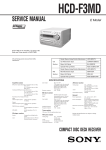
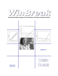
CLEANING OBJECTIVE LENS OF OPTICAL PICK-UP
• In cleaning the objective lens of optical pick-up, be sure the
following below.
1. In cleaning the lens, do not apply an excessive force.
As the optical pick-up is vulnerable, application of excessive
force could damage the lens holder.
2. In cleaning, do not use a cleaner other than exclusive cleaning
liquid (KK-91 or isopropyl alcohol).
3. Wipe the objective lens spirally from center toward outside. (See
Figure A)
CAUTION
Use of controls or adjustments or performance of procedures
other than those specified herein may result in hazardous radiation
exposure.
(Figure A)
4. Eject the disk, if loaded.
5. Disconnect the power cord from the socket to shut off the power
supply.
6. When cleaning the objective lens of optical pick-up in CD, refer
to “HOLDER (BU) ASS’Y” on page XX for removing
HOLDER (BU) ASS’Y.
7
HCD-PX333
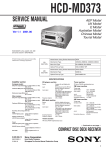
SERVICE POSITION
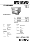
• In checking the MD mechanism deck section (MDM-7X2A), prepare two extension jigs (Part No. J-2501-100-A: 1.00 mm 27 core and
Part No. J-2501-198-A: 1.00 mm 17 core).
• In checking the CD mechanism deck section (CDM55A-21BD53), prepare extension jig (Part No. J-2501-075-A: 1.00 mm 21 core.)
Connect extension jig (J-2501-198-A) to the
BD (MD) board (CN103) and MD DIGITAL board (CN1004).
MD mechanism deck section
(MDM-7X2A)
CN103
Connect extension jig (J-2501-100-A) to the
BD (MD) board (CN102) and MD DIGITAL board (CN1003).
CN102
BD (MD) board
CN1004
CN1003
CD mechanism deck section
(CDM55A-21BD53)
BD (CD) board
CN101
CN1005
MD DIGITAL board
CN1002
Pin 2 (GND)
Connect extension jig (J-2501-075-A)
to the BD (CD) board (CN101) and
MD DIGITAL board (CN1002).
CN1005
Pin 3 (OUTSW)
harness
Note on Checking CD Mechanism Deck Section
In performing the operation check with the CD mechanism deck section removed from the main unit, the CD disc loading will be disabled if
the connector cable between MD DIGITAL board (CN1005) and LOADING board (CN151) is disconnected. Accordingly, make preparation
through the following steps.
1. Insert the CD disc for test with the set assembled.
2. Unplug the AC power cord to turn the power off, and remove the CD mechanism deck section. (Disconnect the connector cable between
MD DIGITAL board (CN1005) and LOADING board (CN151), and also the connector cable between MD DIGITAL board (CN1002)
and BD (CD) board (CN101))
3. Connect the CN1005 pin 3 (OUTSW) and pin 2 (GND) on the MD DIGITAL board with a lead wire.
4. Connect the connectors between MD DIGITAL board (CN1002) and BD (CD) board (CN101) with the extension tool (part No.: J-2501075-A).
Note 1:
Note 2:
8
Under this condition, the CD can be played but the disc loading operation is disabled.
After checking, disconnect the lead wire connected in step 3.
HCD-PX333
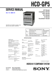
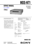
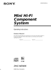
JIG FOR CHECKING BD (MD) BOARD WAVEFORM
The special jig (J-2501-196-A) is useful for checking the waveform of the BD (MD) board. The names of terminals and the checking items
to be performed are shown as follows.
I+3V
IOP
GND
TE
FE
VC
RF
: For measuring IOP (Check the deterioration of the optical pick-up laser)
: For measuring IOP (Check the deterioration of the optical pick-up laser)
: Ground
: Tracking error signal (Traverse adjustment)
: Focus error signal
: Reference level for checking the signal
: RF signal (Check jitter)
CN105
IOP
TE
I+3V
GND
FE
VC
RF
1
I+3V
IOP
GND
TE
FE
VC
RF
I+3V
IOP
GND
TE
FE
VC
RF
for
MDM-7X2A
7
9
HCD-PX333
Note 1: About “R”
As this unit has only a few buttons, some operations require the use of remote commander (RM-S55EN/provided with unit: 1-476-664-21)
buttons. These operations are indicated as “R” in this manual.
Example: MENU/NO “R” ... Press the [MENU/NO] button of the remote commander.
Note 2: Incorrect operations may be performed if the MD test mode is not entered properly.
In this case, press the ?/1 button to turn the power off, and retry to enter the MD test mode.
IOP DATA RECORDING AND DISPLAY WHEN OPTICAL PICK-UP AND NON-VOLATILE MEMORY (IC195 OF BD
(MD) BOARD) ARE REPLACED
The IOP value labeled on the optical pick-up can be recorded in the non-volatile memory. By recording the value, it will eliminate the need
to look at the value on the label of the optical pick-up. When replacing the optical pick-up or non-volatile memory (IC195 of BD (MD)
board), record the IOP value on the optical pick-up according to the following procedure.
Record Procedure:
1. Press the ?/1 button to turn the power on.
2. Press the [FUNCTION] button to set the MD function.
3. Press three buttons of [M> TUNING+], [REC MODE], and .m (MD) simultaneously to enter the MD test mode and display
“[Check]”.
4. Press the . “R” or > “R” button to display “[Service]”.
5. Press the ENTER/YES “R” button to display “AUTO CHECK”, and press the > “R” button to display “Iop Write”.
6. Press the ENTER/YES “R” button.
7. The display becomes “Ref= @@@.@” (@ is an arbitrary number) and the numbers which can be changed will blink.
8. Input the IOP value written on the optical pick-up.
To select the number : Press the . “R” or > “R” button.
To select the digit
: Press the [REC MODE] button after press the [CD SYNC NORMAL] button to display “IT”.
9. When the ENTER/YES “R” button is pressed, the display becomes “Measu=@@@.@” (@ is an arbitrary number).
10. As the adjustment results are recorded for the step 9 value. Leave it as it is and press the ENTER/YES “R” button.
11. “Complete!” will be displayed momentarily. The value will be recorded in the non-volatile memory and the display will become “Iop
Write”.
12. Press the [REPEAT STEREO/MONO] button to complete. “Initialize” will be displayed and release the MD test mode.
Display Precedure:
1. Press the ?/1 button to turn the power on.
2. Press the [FUNCTION] button to set the MD function.
3. Press three buttons of [M> TUNING+], [REC MODE], and .m (MD) simultaneously to enter the MD test mode and display
“[Check]”.
4. Press the . “R” or > “R” button to display “[Service]”.
5. Press the ENTER/YES “R” button to display “AUTO CHECK”, and press the > “R” button to display “Iop Read”.
6. Press the ENTER/YES “R” button.
7. “@@.@/##.#” is displayed and the recorded contents are displayed.
@@.@ : Indicates the Iop value labeled on the pick-up.
##.#
: Indicates the Iop value after adjustment.
8. Press the [REPEAT STEREO/MONO] button to complete. “Initialize” will be displayed and release the MD test mode.
WHEN MEMORY NG IS DISPLAYED
If the nonvolatile memory data is abnormal, “E001 MEMORY NG” will be displayed so that the MD deck does not continue operations. In
this case, set the test mode promptly and perform the following procedure.
Procedure:
1. Enter the MD test mode.
2. Normally a message for selecting the test mode will be displayed. However if the nonvolatile memory is abnormal, the following will be
displayed “INIT EEP?”.
3. Press the x (MD) and Z (MD) buttons simultaneously.
4. Press the . “R” or > “R” button to display “MDM-7X2A”.
5. Press the ENTER/YES “R” button. If the nonvolatile memory is successfully overwritten, the normal MD test mode will be set and a
message to select the MD test mode will be displayed.
10
HCD-PX333
CHECKS PRIOR TO PARTS REPLACEMENT AND ADJUSTMENTS IN MD
Before performing repairs, perform the following checks to determine the faulty locations up to a certain extent.
Details of the procedures are described in “5 Electrical Adjustments”.
Criteria for Determination
(Unsatisfactory if specified value is not satisfied)
Laser power check
(6-2 : See page 40)
Traverse check
(6-6 : See page 41)
Focus bias check
(6-7 : See page 42)
C PLAY check
(6-8 : See page 42)
Self-recording/playback
check
(6-9 : See page 42)
Temperature
compensation
offset check
(6-1 : See page 40)
• 0.9 mW power
Specified value : figure1
• 8.4 mW power
Specified value : figure2
Iop (at 8.4mW)
• Labeled on the optical pick-up
Iop value ± 10mA
• Traverse waveform
Specified value : Below 10% offset
• Error rate check
Specified value : For points A and B
C1 error : About 200
AD error : below 2
For point C
C1 error: 20
AD error: below 2
• Error rate check
Specified value:
a.
When using test disc (MDW-74/GA-1)
C1 error : Below 20
AD error : 00
b.
When using check disc (TDYS-1)
C1 error : Below 20
• CPLAY error rate check
Specified value:
C1 error : Below 20
AD error : Below 2
• Unsatisfactory if displayed as T=@@ (##) [NG]”
NG
(@@, ## are both arbitrary numbers)
Measure if unsatisfactory
• Clean the optical pick-up
• Adjust again
• Replace the optical pick-up
• Replace the optical pick-up
• Replace the optical pick-up
• Replace the optical pick-up
• Replace the optical pick-up
If always unsatisfactory:
• Replace the overwrite head
• Check for disconnection of the circuits around the
overwrite head
If occasionally unsatisfactory:
• Check if the overwrite head is distorted
• Check the mechanism around the sled
• Check for disconnection of the circuits around
D101 (BD (MD) board)
• Check the signals around IC101, IC151, CN102,
CN103 (BD (MD) board)
Note:
The criteria for determination above is intended merely to determine if satisfactory or not, and does not serve as the specified value for adjustments.
When performing adjustments, use the specified values for adjustments.
Figure1:
SPECIFIED VALUE
KMS-262A
KMS-262E
0.84 to 0.92 mW
0.90 to 0.96 mW
KMS-262A
KMS-262E
8.1 to 8.7 mW
8.4 to 8.9 mW
Figure2:
SPECIFIED VALUE
11
HCD-PX333
RETRY CAUSE DISPLAY MODE IN MD
• In this test mode, the causes for retry of the unit during recording can be displayed on the liquid crystal display. During playback, the
“track mode” for obtaining track information will be set.
This is useful for locating the faulty part of the unit.
• The following will be displayed :
During recording and stop : Retry cause, number of retries, and number of retry errors.
During playback
: Information such as type of disc played, part played, copyright.
These are displayed in hexadecimal.
Precedure:
1. Load a recordable disc whose contents can be erased into the unit.
2. Press the MENU/NO “R” button. When “Edit Menu” is displayed on the liquid crystal display, press the . “R” or
> “R” button to display “All Erase?”.
3. Press the ENTER/YES “R” button.
4. When “All Erase??” is displayed on the liquid crystal display, the music calendar number blinks.
5. Press the ENTER/YES “R” button to display “Complete!”.
6. Press the [REC/REC IT] button to start recording. Then press the [N X MD] button and start recording. If recording cannot be performed, press
the [FUNCTION] button and set a different function.
7. Press three buttons of . m , [PLAY MODE TUNING MODE] and [N XMD] simultaneously to enter the retry cause display mode.
8. To check the “track mode”, press the [N X MD] button to start playback.
9. To release this mode, press the I/1 button to turn the power off. When “TOC” goes off, disconnect the power plug from the outlet.
If the test mode cannot be released, refer to “MC COLD RESET” on page 31.
Fig. 1 Reading the Test Mode Display
(During recording and stop)
Fig. 2 Reading the Test Mode Display
(During playback)
RTs@@c##e**
Liquid crystal display
@@ ###** $$
Liquid crystal display
@@ : Cause of retry
## : Number of retries
** : Number of retry errors
@@ :
## :
** :
$$ :
Parts No. (name of area named on TOC)
Cluster
Sector Address
Track mode (Track information such as
copyright information of each part)
Reading the Retry Cause Display
Higher Bits
Lower Bits
HexaHexadecimal 8 4 2 1 8 4 2 1 decimal Cause of Retry
Bit
b7 b6 b5 b4 b3 b2 b1 b0
Binary
0 0 0 0 0 0 0 1
01
shock
0
0
0
0
0
0
1
0
02
ader5
0
0
0
0
0
1
0
0
0
0
1
0
0
0
0
1
0
0
0
0
1
0
0
0
0
1
0
0
0
0
1
0
0
0
0
0
0
0
0
0
0
0
0
0
0
0
0
0
04
08
10
20
40
80
Discontinuous address
DIN unlock
FCS incorrect
IVR rec error
CLV unlock
Access fault
Occurring conditions
When track jump (shock) is detected
When ADER was counted more than five times
continuously
When ADIP address is not continuous
When DIN unlock is detected
When not in focus
When ABCD signal level exceeds the specified range
When CLV is unlocked
When access operation is not performed normally
Reading the Display:
Convert the hexadecimal display into binary display. If more than two causes, they will be added.
Example
When 42 is displayed:
Higher bit : 4 = 0100 t b6
Lower bit : 2 = 0010 t b1
In this case, the retry cause is combined of “CLV unlock” and “ader5”.
When A2 is displayed:
Higher bit : A = 1010 t b7 + b5
Lower bit : 2 = 0010 t b1
The retry cause in this case is combined of “Access fault”, “IVR rec error”, and “ader5”.
12
HCD-PX333
Reading the Retry Cause Display
Higher Bits
Hexadecimal 8 4 2
b7 b6 b5
Bit
Binary
0 0 0
0 0 0
0 0 0
0 0 0
0 0 0
0 0 1
0 1 0
1 0 0
1
b4
0
0
0
0
1
0
0
0
Lower Bits
8
b3
0
0
0
1
0
0
0
0
4
b2
0
0
1
0
0
0
0
0
2
b1
0
1
0
0
0
0
0
0
HexaDetails
1 decimal
b0
When 0
When 1
1
01
Emphasis OFF
Emphasis ON
0
02
Monaural
Stereo
0
04
This is 2-bit display. Normally 01.
0
08
01:Normal audio. Others:Invalid
0
10
Audio (Normal)
Invalid
0
20
Original
Digital copy
0
40
Copyright
No copyright
0
80
Write prohibited
Write allowed
Reading the Display:
Convert the hexadecimal display into binary display. If more than two causes, they will be added.
Example When 84 is displayed:
Higher bit : 8 = 1000 t b7
Lower bit : 4 = 0100 t b2
In this case, as b2 and b7 are 1 and others are 0, it can be determined that the retry cause is combined of “Emphasis OFF”, “Monaural”,
“Original”, “Copyright”, and “Write allowed”.
Example When 07 is displayed:
Higher bit : 0 = 0000 t All 0
Lower bit : 7 = 0111 t b0 + b1 + b2
In this case, as b0, b1, and b2 are 1 and others are 0, it can be determined that the retry cause is combined of “Emphasis ON”, “Stereo”,
“Original”, “Copyright”, and “Write prohibited”.
Hexadecimal t Binary Conversion Table
Hexadecimal
0
1
2
3
4
5
6
7
Binary
0000
0001
0010
0011
0100
0101
0110
0111
Hexadecimal
8
9
A
B
C
D
E
F
Binary
1000
1001
1010
1011
1100
1101
1110
1111
13
HCD-PX333
CD SECTION
CD AGING MODE
Procedure:
1. Press the ?/1 button to turn the power on.
2. Press the [FUNCTION] button to set the CD function, and press the Z (CD) button to insert a disc.
3. Press three buttons of x (CD) , [.m TUNING-] and x (MD) simultaneously.
4. The set displays “AGING SEL=00”. Between it is displayed, press the Z (CD) button to start CD aging mode.
5. The sequence during the CD aging mode is following as below.
Note: If the triple button pressing failed to activate the CD test mode, press the [.m TUNING-] button, and the x (MD) button in this
order while pressing the x (CD) button. Also, release the x (MD), [ .m TUNING-] and x (CD) buttons in this order, when
releasing the buttons.
CD aging mode sequence:
CD disk tray open
CD disc tray close
TOC read
Playback track 1
Playback last track
Display aging number
6. To release from this mode, press the ?/1 button to turn the power off.
Note: Refer to “Error History Display Mode” (page 5) for display at an error occurred.
14
HCD-PX333
CD-TEXT TEST DISC
This unit is able to display the test data (character information) written in the CD on its fluorescent indicator tube.
The CD-TEXT TEST DISC (TGCS-313:4-989-366-01) is used for checking the display.
To check, perform the following procedure.
Checking Method:
1. Press the ?/1 button to turn the power on, set the disc to the disc table with the “test disc” label facing up, and chuck the disc.
2. Press the [CD N X] button and playback the disc.
3. The following will be displayed on the liquid crystal display.
Display : 1kHz/0db/L&R
4. Pressing the [.m TUNING-] or [M > TUNING+] button, select the track. The text data of each track will be displayed.
For details of the displayed contents for each track, refer to “Table 1 : CD-TEXT TEST DISC TEXT Data Contents” and “Table 2 : CDTEXT TEST DISC Recorded Contents and Display”.
Restrictions in CD-TEXT Display
In this unit, some special characters will not be displayed properly. These will be displayed as a space or a character resembling it. For details,
refer to “Table 2 : CD-TEXT DISC Recorded Contents and Display”.
Table 1 : CD-TEXT TEST DISC TEXT Data Contents (TRACKS No. 1 to 41:Normal Characters)
TRACK
No.
Displayed Contents
TRACK
Displayed Contents
No.
1
1kHz/0dB/L&R
22
1kHz/–90dB/L&R
2
20Hz/0dB/L&R
23
Infinity Zero w/o emphasis//L&R
3
40Hz/0dB/L&R
24
Infinity Zero with emphasis//L&R
4
100Hz/0dB/L&R
25
400Hz+7kHz(4:1)/0dB/L&R
5
200Hz/0dB/L&R
26
400Hz+7kHz(4:1)/–10dB/L&R
6
500Hz/0dB/L&R
27
19kHz+20kHz(1:1)/0dB/L&R
7
1kHz/0dB/L&R
28
19kHz+20kHz(1:1)/–10dB/L&R
8
5kHz/0dB/L&R
29
100Hz/0dB/L*
9
7kHz/0dB/L&R
30
1kHz/0dB/L*
10
10kHz/0dB/L&R
31
10kHz/0dB/L*
11
16kHz/0dB/L&R
32
20kHz/0dB/L*
12
18kHz/0dB/L&R
33
100Hz/0dB/R*
13
20kHz/0dB/L&R
34
1kHz/0dB/R*
14
1kHz/0dB/L&R
35
10kHz/0dB/R*
15
1kHz/–1dB/L&R
36
20kHz/0dB/R*
16
1kHz/–3dB/L&R
37
100Hz Squer Wave//L&R
17
1kHz/–6dB/L&R
38
1kHz Squer Wave//L&R
18
1kHz/–10dB/L&R
39
1kHz w/emphasis/–0.37dB/L&R
19
1kHz/–20dB/L&R
40
5kHz w/emphasis/–4.53dB/L&R
20
1kHz/–60dB/L&R
41
16kHz w/emphasis/–9.04dB/L&R
21
1kHz/–80dB/L&R
Note: The contents of Track No. 1 to 41 are the same as those of the current TEST DISC-their titles are displayed.
15
HCD-PX333
Table 2: CD-TEXT TEST DISC Recorded Contents and Display
(In this unit, some special characters cannot be displayed. This is not a fault)
TRACK
No.
Recorded contents
42
! ” # $%& ´
(21h to 27h)1kHz 0dB L&R
T All the same
43
( )
(28h to 2Fh)
T All the same
*
+ , – . /
44
01234567
(30h to 37h)
T All the same
45
89 : ; <=>?
(38h to 3Fh)
T All the same
46
@A B C D E F G
(40h to 47h)
T All the same
47
H I J K L MNO
(48h to 4Fh)
T All the same
48
P Q R S T U V W (50h to 57h)
T All the same
49
XYZ [ ¥ ] ^ _
(58h to 5Fh)
T All the same
50
′
ab c de f g
(60h to 67h)
T All the same
51
h i j k l mn o
(68h to 6Fh)
T All the same
52
pq r s t u vw
(70h to 77h)
T All the same
53
x y z { I } ~
(78h to 7Fh)
T All the same
i ¢£¤¥ §
C ª ¬ PR–
54
(A0h to A7h) 8859-1
(A0h to A7h) 8859-1
(A8h to AFh)
(A8h to AFh)
′
µ¶ •
(B0h to B7h)
(B0h to B7h)
1
4
1
2
¿
(B8h to BFh)
À Á Â Ã Ä Å ÆÇ
(C0h to C7h)
55
•
±
57
†
1
58
59
È ÉÊË Ì Í Î Ï
(C8h to CFh)
EEEE I I I I
(C8h to CFh)
60
D ÑÒÓÔÕÖ
Ø Ù Ú Û Ü Y˙ ß
(D0h to D7h)
DNOOOOO
(D0h to D7h)
(D8h to DFh)
O UUUUY
(D8h to DFh)
62
à á â ã ä åæç
(E0h to E7h)
aaaaaa
c
(E0h to E7h)
63
è éêë ì í î ï
(E8h to FFh)
eeee i i i i
(E8h to EFh)
64
∂ ñòóôõö÷
(F0h to F7h)
dnooooo
(F0h to F7h)
65
ø ù ú û ü y´
(F8h to FFh)
ouuuu y
66
No.66
T All the same
67
No.67
T All the same
56
61
to
99
16
Display
2
º
to
No.99
3
3
4
ÿ
(B8h to BFh)
AAAAAA
C
y
to
T All the same
(C0h to C7h)
(F8h to FFh)
HCD-PX333
SECTION 2
GENERAL
This section is extracted
from instruction manual.
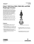
Parts Identification
The items are arranged in alphabetical order. Refer to the pages indicated in parentheses for details
Main unit
1
2
3 4
ws
5
wa
w;
6
7
8
ql
9
qk qj
CD disc tray 9 (8)
CD SYNC HIGH q; (17)
CD SYNC NORMAL qa (17)
CD N X ws (9)
Display window 3
FUNCTION qh (9, 13, 18, 25, 41)
MD insertion slot 2 (13)
MD NX 6 (13)
PHONES jack qj
qh qg qf qd qs qa
PLAY MODE qg (9, 13, 24)
REC/REC IT qs (18)
REC MODE qd (20)
REPEAT qf (9, 14)
STEREO/MONO ql (35)
TUNER/BAND qd (34)
TUNING MODE qg (34)
TUNING +/– w; (34)
VOLUME +/– qk
q;
BUTTON DESCRIPTIONS
?/1 1
ZMD 4
x (MD) 5
m/M (MD) 7
./> (MD) 7
ZCD 8
m/M (CD) w;
./> (CD) w;
x (CD) ws
4
17
HCD-PX333
Remote Control
1
2
qk
qj
3
4
Parts Identification
w;
ql
5
6
7
qh
qg
qf
8
9
qd
q;
qs
qa
CLEAR 6 (11, 15, 26, 36)
CLOCK/TIMER SELECT ql
(38)
CLOCK/TIMER SET ql (7, 38)
DBFB qa (37)
DISPLAY qj (8, 11, 15)
ENTER/YES qg (7, 10, 14, 23,
25, 34, 38)
FUNCTION qf (9, 13, 18, 25, 41)
Letter/Number buttons 5 (10, 14,
25)
MD z REC qs (18)
MENU/NO qg (11, 23)
NAME EDIT 8 (12, 25, 36)
PLAY MODE qk (9, 13, 24)
PRESET EQ qa (37)
REPEAT qk (9, 14)
SCROLL 4 (12, 26)
SELECT 8 (12, 25)
SLEEP w; (37)
STEREO/MONO 2 (35)
TIME qj (8, 11, 15)
TIME MACHINE REC qs (19)
TUNER/BAND 9 (34)
TUNING MODE 3 (34)
VOLUME +/– q;
BUTTON DESCRIPTIONS
?/1 1
M/CURSORt 7
>/+ 7
N (MD) qd
N (CD) qd
X qd
x qd
m/TCURSOR qh
./– qh
Setting the time
1 Turn on the system.
2 Press CLOCK/TIMER SET on the
remote.
Proceed to step 5 when you set the clock for
the first time.
3 Press . or > on the remote to
select “CLOCK SET?”.
4 Press ENTER/YES on the remote.
5 Press + or – on the remote to set the
day.
6 Press ENTER/YES or M on the
remote.
The hour indication flashes.
5
7 Press + or – on the remote to set the
hour.
8 Press ENTER/YES or M on the
remote.
The minute indication flashes.
9 Press + or – on the remote to set the
minute.
10 Press ENTER/YES on the remote.
The clock starts working.
If you made a mistake
Press m or M on the remote repeatedly
until the incorrect item flashes, then set it
again.
To change the preset time
Start over from step 1.
18
HCD-PX333
SECTION 3
DISASSEMBLY
• This set can be disassembled in the order shown below.
SET
CASE
(Page 20)
BACK PANEL,
SP BOARD, TUNER
(Page 22)
FRONT PANEL SECTION
(Page 20)
JACK BOARD,
BL BOARD, VOL BOARD
(Page 21)
REC BOARD, VOL BOARD
(Page 21)
POWER TRANSFORMER,
DC FAN
(Page 22)
AMP BOARD
(Page 23)
HOLDER (BU) ASSY
(Page 28)
TRAY (CDM),
LOADING BOARD
(Page 29)
MD DIGITAL BOARD
(Page 28)
MD MECHANISM DECK
(MDM-7X2A)
(Page 24)
BASE UNIT (BU-21BD53),
HOLDER (55-BU21),
(Page 29)
CAM
(CDM55)
(Page 30)
HOLDER ASSY
(Page 25)
OVER WRITE HEAD
(HR901),
BD (MD) BOARD
(Page 24)
LOADING MOTER ASSY
(M103)
(Page 25)
SLED MOTOR ASSY
(M102)
(Page 26)
OPTICAL PICK-UP
(KMS-262)
(Page 26)
MAIN BOARD,
POWER BOARD
(Page 23)
CD MECHANISM DECK
(CDM55A-21BD53)
(Page 27)
SPINDLE MOTOR ASSY
(M101)
(Page 27)
19
HCD-PX333
3-1. CASE
1 two screws
(CASE3 TP2)
4
5 case
3
3
2 two screws
(CASE3 TP2)
3-2. FRONT PANEL SECTION
4 wire (flat type)(23 core)
(CN100)
5 front panel section
3
2 three claws
1 three screws (+BVTT3 × 6)
20
HCD-PX333
3-3. JACK BOARD, BL BOARD, PANEL BOARD, LCD
5 four screws (+BVTP 2.6 × 8)
4 JACK board
qf PANEL board
qd holder (LCD)
9 plate (LCD), light guide
8 sheet, diffusion
6 wire (flat type)(23 core)
(CN601)
7 LCD
1 two screws (+BVTP 2.6 × 8)
2 connector 2p (CN604)
3 connector 2p (CN606)
qs spacer (LCD)
qa BL board
q; lid (LCD holder)
3-4. REC BOARD, VOL BOARD
5 shaft (lid rec)
4 screw (+BVTP 2.6 × 8)
qa two screws (+BVTP 2.6 × 8)
qs VOL board
1 screw (+PTPWH M2.6)
2 screw (+BVTP 2.6 × 8)
3 spring (lid func), leaf
6
7 three screws (+BVTP 2.6 × 8)
8REC board
9 buttan (REC)
q; lid (REC)
21
HCD-PX333
3-5. BACK PANEL, SP BOARD, TUNER
4 back panel
5 two connectors
(CN103, 801)
1 four screws
(+BVTP3 ×10)
7 wire (flat type)
(11 core)
2 four screws
(+BVTP3 ×10)
6 SP board
3
9 tuner pack (FM/AM)
8 screw (+BVTP3 ×10)
3-6. TRANSFORMER, POWER and DC FAN
4 transformer, power (T900)
2 connector 2p
(CN992)
6 two screws
(+B3 × 16)
1 connector 4p
(CN993)
8 DC fan
(M901)
7 spacer (FAN)
5 Remove two solderings.
3 four screws
(+BVTT 3 × 6)
22
HCD-PX333
3-7. MAIN BOARD, POWER BOARD
8 connector 2p (CN992)
1 connector 4p (CN993)
7 connector 2p (CN991)
4 wire (flat type)(31 core)
(CN107)
9 screw (+BVTT 3 × 6)
5 wire (flat type)(11 core)
(CN105)
qa POWER board
6 MAIN board
3 connector (CN101)
2 two screws (+BVTT 3 × 6)
q; two screws (+BVTT 3 × 6)
3-8. AMP BOARD
9 screw (+BV 3 × 10)
qa heat sink
1 screw (+BVTT 3 × 6)
2 screw (+BVTT 3 × 6)
q; bracket (H/S R)
4 three screws (+BVTP 3 × 10)
7 screw (+BV 3 × 10)
8 bracket (H/S F)
5 two screws (+BV 3 × 10)
6 AMP board
3 screw (+BVTT 3 × 6)
23
HCD-PX333
3-9. MD MECHANISM DECK (MDM-7X2A)
4 ground wire
3 screw (1.7 × 3), btn
5 four screws
(+BVTPWH M3), step
1 wire (flat type)(17 core)(CN103)
2 wire (flat type)(27 core)(CN102)
7 two insulators
8 MD mechanism deck
(MDM-7X2A)
7 two insulators
6
3-10. OVER WRITE HEAD (HR901), BD (MD) BOARD
Note : When the 1 connector (CN104) is removed first
of all, the overwrite head (HR901) and the BD
(MD) board can be removed to either side.
2 screw (+P1.7 × 6)
3 head, over write (HR901)
Note : The overwrite head (HR901) is very fragile and
easy to be damaged. Be careful to handle it
gently with care not to break it.
4 Remove four solderings
8 BD (MD) board
6
1 connector (CN104)
7 flexible board (CN101)
4 Remove five solderings
5 two screws (+BTP2 × 6)
24
HCD-PX333
3-11. HOLDER ASSY
3
2 claw
5 holder assy
4 boss
4 boss
1 spring (holder), tension
3-12. LOADING MOTOR ASSY (M103)
1 belt (loading)
2 two screws
(+PWH1.7 × 3.5)
3 motor assy, loading
(M103)
25
HCD-PX333
3-13. SLED MOTOR ASSY (M102)
3
5 Slide in the direction of arrow A while
pulling up the claw.
4 slider (EJ)
A
8 lever (head)
6 slider
2 guide (L)
1 two screws
(+BTP2 × 6)
9 two screws
(+PWH1.7 × 3.5)
7 lever (CHG)
q; motor assy, sled (M102)
3-14. OPTICAL PICK-UP (KMS-262)
qa optical pick-up
(KMS-262)
7 Pull out the main shaft.
1 flexible board
q; base, SL
9 screw (+P1.7 × 6)
8
6 two screws (+K2 × 6)
4 screw
(+BTP2 × 6)
5 base (BU-A)
3 gear (SD)
2 screw (M1.7), tapping
26
HCD-PX333
3-15. SPINDLE MOTOR ASSY (M101)
2 motor assy, spindle
(M101)
1 three screws (M1.7),
tapping (M1.7)
3-16. CD MECHANISM DECK (CDM55A-21BD53)
2 four screws (+BVTT 3 × 6)
1 wire (flat type)(21 core)
(CN1002)
3
8 panel, loading
4 screw (+BVTT3 × 6)
7 two claws
5
q; CD mechanism deck
(CDM55A-21BD53)
9 connector 5p (CN151)
6 two claws
27
HCD-PX333
3-17. MD DIGITAL BOARD
1 wire (flat type)(17 core)
(CN1004)
2 wire (flat type)(27 core)
(CN1003)
4 two claws
5
8 MD DIGITAL board
7 connector 5p (CN1005)
6 wire (flat type)(31 core)
(CN1001)
3 screw (+BV 3 × 10)
3-18. HOLDER (BU) ASSY
2 screw (+PTPWH M2.6),
floating
4 holder (BU) assy
3
A
1 Rotate the lever (SW) in the direction of arrow A.
28
HCD-PX333
3-19. BASE UNIT (BU-21BD53), HOLDER (55-BU21)
1 three screws (+PTPWH M2.6), floating
2 screw (+PTPWH M2.6),
floating
5 base unit (BU-21BD53)
4 insulator (BU21)
4 three insulators (BU21)
6 three springs, cone coil
6 spring, cone coil
3
8 holder (55-BU21)
7 shaft (BU21)
3-20. TRAY (CDM), LOADING BOARD
2 belt (CDM55)
claw
A
1 Rotate the gear (B) in the
direction of arrow A.
3 Pull the tray (CDM)
while pushing the claw.
4 two screws
(+BTP2.6 × 6)
5 LOADING board
29
HCD-PX333
3-21. CAM (CDM55)
3 spacer (55)
4 pulley (LDG)
6 gear (B)
5 gear (A)
1 spring, torsion
7 roller
2 lever (SW)
30
8 cam (CDM55)
HCD-PX333
SECTION 4
TEST MODE
Note 1: About “R”
As this unit has only a few buttons, some operations require the use of remote commander (RM-S55EN/provided with unit: 1-476-664-21)
buttons. These operations are indicated as “R” in this manual.
Example: MENU/NO “R” ...Press the [MENU/NO] button of the remote commander.
Note 2: Incorrect operations may be performed if the MD test mode is not entered properly.
In this case, press the ?/1 button to turn the power off, and retry to enter the MD test mode.
MC COLD RESET
• The cold reset clears all data including preset data stored in the RAM to initial conditions. Execute this mode when returning the set to
the customer.
Procedure:
1. Press the ?/1 button to turn the power on.
2. Press three buttons of [VOLUME –] , [REC MODE], and x (MD) simultaneously.
3. The set is reset, and displays “See you”, then becomes standby status.
AMP TEST
Procedure:
1. Press the ?/1 button to turn the power on.
2. Press three buttons of .m TUNING – , M > TUNING + ,and M > (MD) simultaneously.
3. Each buttons are pressed, it changes display as follows.
Button
Display
x (CD)
7[TESTMIN]
REC MODE
8[TESTMID]
x (MD)
9[TESTMAX]
4. Press the [VOLUME +] button, the display switches “VOLUME 21” to “VOLUME MAX”. And the display returns to the original
display after a few second.
5. Press the [VOLUME -] button, the display switches “VOLUME 21” to “VOLUME MIN”. And the display returns to the original
display after a few second.
6. To release from this mode, press the ?/1 button to turn the power off and cold reset.
VERSION DISPLAY
Procedure:
1. Press the ?/1 button to turn the power on.
2. Press three buttons of .m TUNING – , M > TUNING + , and [TUNER/BAND] simultaneously.
3. Enter the version display mode and STR version is shown in the upper position, the distination is shown in the lower position
4. Each time the x (MD) button is pressed, it changes display STR version → CD version → MD version → STR version → ...
5. To release from this mode, press the ?/1 button to turn the power off.
LCD AND LED TEST
Procedure:
1. Press the ?/1 button to turn the power on.
2. Press three buttons of .m TUNING – , M > TUNING + , and x (MD) simultaneously.
3. Liquid crystal display and LEDs are all turned on.
4. Each time the x (MD) button is pressed, it changes display all turned on → all turned off → pattern 1 → pattern 2 → all turned on → ...
5. Each time the x (CD) button is pressed, it changes LED indication all turned on → all turned off → “?/1” → “REC” → “N” (MD)
→ “X” (MD) → “N” (CD) → “X” (CD) → all turned on → ...
6. To release from this mode, press the ?/1 button to turn the power off.
PATTERN 1
PATTERN 2
CD
MD
OVER
TRACK
TOC
DBFB
OVER
DISC
PRESET
SHUFFLE
SYNC
1
IT HCMS
c DAILY c REC 2
2
MONO
TEXT
TUNED
MANUAL AUTO
PROGRAM REPEAT
S.F EDIT
REC
NORM HIGH L-SYNC
MONO
1 3 SLEEP
LP 4
KEY TEST
Procedure:
1. Press the ?/1 button to turn the power on.
2. Press three buttons of .m TUNING – , M > TUNING + , and .m (MD) simultaneously.
3. Enter the key test mode and display “KEY00”.
4. Each time a button is pressed, “KEY” value increases. However, once a button is pressed, it is no longer taken into account.
5. To release from this mode, press three buttons in the same manner as step 2 , or disconnect the power cord.
31
HCD-PX333
MD SECITON
1. PRECAUTIONS FOR USE OF TEST MODE
• As operations related to loading will be performed regardless of the test mode operations being performed, be sure to check that the disc
is stopped before setting and removing it.
Even if the Z (MD) button is pressed while the disc is rotating during continuous playback, continuous recording, etc., the disc will not
stop rotating.
Therefore, it will be ejected while rotating.
Be sure to press the Z (MD) button after pressing the MENU/NO “R” button and the rotation of disc is stopped.
1-1. Recording laser emission mode and operating buttons
• Continuous recording mode (CREC 2MODE)
• Laser power check mode (LDPWR CHECK)
• Laser power adjustment mode (LDPWR ADJUST)
• Comparison with initial Iop value written in nonvolatile memory (Iop Compare)
• Write current Iop value in read nonvolatile memory using microprocessor (Iop NV Save)
• Traverse (MO) check (EF MO CHECK)
• Traverse (MO) adjustment (EF MO ADJUST)
• When pressing the [REC/REC IT] button.
2. SETTING THE TEST MODE
The following are two methods of entering the test mode.
Procedure 1: 1. Press the ?/1 button to turn the power on.
2. Press the [FUNCTION] button to set the MD function.
3. Press three buttons of M > TUNING + , [REC MODE], and . m (MD) simultaneously.
When the test mode is set, “[Check]” will be displayed. Pressing the . “R” or > “R” button between the following
three groups; ···Tt [Check] Tt [Service] Tt [Develop] Tt ···.
Procedure 2: 1. Press the ?/1 button to turn the power on.
2. Press the [FUNCTION] button to set the MD function.
3. Press three buttons of x (CD) , [REC MODE], and M > (MD) simultaneously.
When the test mode is set, “AUTO CHECK” (C01) will be displayed. By setting the test mode using this method, only the
“Check” group of procedure1 can be executed.
Note: Do not use the test mode in the [Develop] group.
If used, the unit may not operate normally.
If the [Develop] group is set accidentally, press the MENU/NO “R” button immediately to exit the [Develop] group.
3. RELEASING THE TEST MODE
Press the [REPEAT STEREO/MONO] button to display “Initialize”, then release the MD test mode.
4. BASIC OPERATIONS OF THE TEST MODE
All operations are performed using the . “R” , > “R” , ENTER/YES “R” and MENU/NO “R” .
The functions of these buttons are as follows.
Function name
. “R” , > “R” buttons
Function
Changes parameters and modes
ENTER/YES “R” button
Proceeds onto the next step. Finalizes input
MENU/NO “R” button
Returns to previous step. Stops operations
32
HCD-PX333
5. SELECTING THE TEST MODE
There are 26 types of test modes as shown below. The groups can be switched by pressing the . “R” or > “R” button. After selecting
the group to be used, press the ENTER/YES “R” button. After setting a certain group, pressing the . “R” or > “R” button switches modes
shown below.
Refer to “Group” in the table for details can be selected.
All items used for servicing can be treated using group [Service]. So be carefully not to enter other groups by mistake.
Note: Do not use the test mode in the [Develop] group.
If used, the unit may not operate normally.
If the [Develop] group is set accidentally, press the MENU/NO “R” button immediately to exit the [Develop] group.
Group
Display
No.
Details
AUTO CHECK
C01
Automatic self-diagnosis
Err Display
C02
Error history display, clear
TEMP ADJUST
C03
Temperature compensation offset adjustment
LDPWR ADJUST
C04
Laser power adjustment
Iop Write
C05
Iop data writing
Iop NV Save
C06
Writes current Iop value in read nonvolatile memory using microprocessor
EF MO ADJUST
C07
Traverse (MO) adjustment
EF CD ADJUST
C08
Traverse (CD) adjustment
FBIAS ADJUST
C09
Focus bias adjustment
AG Set (MO)
C10
Auto gain output level adjustment (MO)
AG Set (CD)
C11
Auto gain output level adjustment (CD)
TEMP CHECK
C12
Temperature compensation offset check
LDPWR CHECK
C13
Laser power check
EF MO CHECK
C14
Traverse (MO) check
EF CD CHECK
C15
Traverse (CD) check
FBIAS CHECK
C16
Focus bias check
ScurveCHECK
C17
S-curve check
VERIFYMODE
C18
Nonvolatile memory check
DETRK CHECK
C19
Detrack check
0920 CHECK
C25
Most circumference check
Iop Read
C26
Iop data display
Iop Compare
C27
Comparison with initial Iop value written in nonvolatile memory
ADJ CLEAR
C28
Initialization of nonvolatile memory for adjustment values
INFORMATION
C31
Display of microprocessor version, etc.
CPLAY2MODE
C36
Continuous playback mode
CREC 2MODE
C37
Continuous recording mode
Mark
Check
Service
• For details of each adjustment mode, refer to “5. Electrical Adjustments”.
For details of “Err Display”, refer to “Self-Diagnosis Function” on page 2.
• If a different mode has been selected by mistake, press the MENU/NO “R” button to release that mode.
• Modes with (×) in the Mark column are not used for servicing and therefore are not described in detail. If these modes are set accidentally, press the MENU/NO “R” button to release the mode immediately.
33
HCD-PX333
5-1. Operating the Continuous Playback Mode
1. Entering the continuous playback mode
(1) Set the disc in the unit. (Whichever recordable discs or discs for playback only are available)
(2) Press the . “R” or > “R” button to display “CPLAY2MODE” (C36).
(3) Press the ENTER/YES “R” button to change the display to “CPLAY2MID”.
(4) When access completes, the display changes to “C =
AD = )”.
Note: The numbers “ ” displayed show you error rates and ADER.
2. Changing the parts to be played back
(1) Press the ENTER/YES “R” button during continuous playback to change the display as below.
“CPLAY2MID” t “CPLAY2OUT” t “CPLAY2IN”
(2)
When pressed another time, the parts to be played back can be moved.
When access completes, the display changes to “C =
AD = )”.
Note: The numbers “ ” displayed show you error rates and ADER.
3. Ending the continuous playback mode
(1) Press the MENU/NO “R” button. The display will change to “CPLAY2MODE” (C36).
(2) Press the Z (MD) button and take out the disc.
Note: The playback start addresses for IN, MID, and OUT are as follows.
IN
MID
OUT
: 40h cluster
: 300h cluster
: 700h cluster
5-2. Operating the Continuous Recording Mode (Use only when performing self-recording/palyback check)
1. Entering the continuous recording mode
(1) Set a recordable disc in the unit.
(2) Press the . “R” or > “R” button to display “CREC 2MODE” (C37).
(3) Press the ENTER/YES “R” button to change the display to “CREC 2MID”.
” and “ REC ” lights up.
(4) When access completes, the display changes to “CREC 2(
Note: The numbers “ ” displayed shows you the recording position addresses.
2. Changing the parts to be recorded
(1) When the ENTER/YES “R” button is pressed during continuous recording, the display changes as below.
“CREC 2MID” t “CREC 2OUT” t “CREC 2IN”
(2)
When pressed another time, the parts to be recorded can be changed. “ REC ” goes off.
” and “ REC ” lights up.
When access completes, the display changes to “CREC 2(
Note: The numbers “ ” displayed shows you the recording position addresses.
3. Ending the continuous recording mode
(1) Press the MENU/NO “R” button. The display changes to “CREC 2MODE” (C37) and “ REC ” goes off.
(2) Press the Z (MD) button and take out the disc.
Note 1: The recording start addresses for IN, MID, and OUT are as follows.
IN
MID
OUT
: 40h cluster
: 300h cluster
: 700h cluster
Note 2: The MENU/NO “R” button can be used to stop recording anytime.
Note 3: Do not perform continuous recording for long periods of time above 5 minutes.
Note 4: During continuous recording, be careful not to apply vibration.
6. FUNCTIONS OF OTHER BUTTONS
Function
Contents
N X MD
Sets continuous playback when this is pressed in the STOP state. When this is pressed during continuous playback, playback position moves.
x (MD)
Stops continuous playback and continuous recording
M “R”
The sled moves to the outer circumference only when this is pressed
m “R”
The sled moves to the inner circumference only when this is pressed
CD SYNC HIGH
Switches between the pit and groove modes when pressed
PLAY MODE
Switches the spindle servo mode (CLV S y CLV A)
CD SYNC HIGH (*1)
Switches the displayed contents each time the button is pressed
MD Z
Ejects the disc
REPEAT STEREO/MONO
Releases the test mode
*1) Press the [CD SYNC NORMAL] button to light up “IT” indicator, then press the [CD SYNC HIGH] button.
34
HCD-PX333
7. TEST MODE DISPLAYS
Each time the [CD SYNC HIGH] button is pressed, the display changes in the following order.
When CPLAY or CREC are started, the display will forcibly be switched to the error rate display as the initial mode.
1. Mode display
Displays “TEMP ADJUST” (C03), “CPLAY2MODE” (C36), etc.
Mode display
2. Error rate display
Displays the error rate in the following way.
C=
AD = )
C = : Indicates the C1 error.
AD = : Indicates ADER.
Error rate display
Address display
Auto gain display
(Not used in servicing)
3. Address display
The address is displayed as follows. (MO: recordable disc, CD: playback only disc)
h=
s=
(MO pit and CD)
h=
a=
(MO groove)
h = : Indicates the header address.
s = : Indicates the SUBQ address.
a = : Indicates the ADIP address.
Detrack check display
(Not used in servicing)
IVR display
(Not used in servicing)
C1 error and jitter display
(Not used in servicing)
Note: “–” is displayed when servo is not imposed.
AD error and jitter display
(Not used in servicing)
MEANINGS OF OTHER DISPLAYS
Contents
Display
When Lit
When Off
2
Servo ON
Servo OFF
4
Tracking servo OFF
Tracking servo ON
REC
Recording mode ON
Recording mode OFF
SYNC, TRACK
CLV low speed mode
CLV normal mode
L.SYNC
ABCD adjustment completed
PROGRAM
Tracking offset cancel ON
TOC
Tracking auto gain OK
REPEAT
Focus auto gain OK
SF EDIT
Pit
Groove
DISC
High reflection
Low reflection
NORM
CLV S
CLV A
MONO
CLV LOCK
CLV UNLOCK
Tracking offset cancel OFF
35
HCD-PX333
8. AUTOMATIC SELF-DIAGNOSIS FUNCTION
This test mode performs CREC and CPLAY automatically for mainly checking the characteristics of the optical pick-up.
To perform this test mode, the laser power must first be checked.
Perform AUTO CHECK after the laser power check and Iop Compare.
Procedure:
1. Press the . “R” or > “R” button to display “AUTO CHECK” (C01).
2. Press the ENTER/YES “R” button. If “LDPWR
” is displayed, it means that the laser power check has not been performed. In
this case, perform the laser power check and Iop Compare, and then repeat from enter the MD test mode.
3. If a disc is in the mechanical deck, it will be ejected forcibly.
“DISC IN” will be displayed in this case. Load a test disc (MDW-74/GA-1) which can be recorded.
4. If a disc is loaded at step 3, the check will start automatically.
5. When “XX CHECK” is displayed, the item corresponding to XX will be performed.
When “06 CHECK” completes, the disc loaded at step 3 will be ejected. “DISC IN” will be displayed. Load the check disc (TDYS-1).
6. When the disc is loaded in step 5, the check will automatically be resumed from “07 CHECK”.
7. After completing to test item 12, check OK or NG will be displayed. If all items are OK, “CHECK ALL OK” will be displayed. If any item
is NG, it will be displayed as “NG:xxxx”.
When “CHECK ALL OK” is displayed, it means that the optical pick-up is normal. Check the operations of other parts (spindle motor,
sled motor, etc.).
When displayed as “NG:xxxx”, it means that the optical pick-up is faulty. In this case, replace the optical pick-up.
9. INFORMATION
Display the software version.
Procedure:
1. Press the . “R” or > “R” button to display “INFORMATION” (C31).
2. Press the ENTER/YES “R” button.
3. The software version will be displayed.
4. Press the MENU/NO “R” button to end this mode.
36
HCD-PX333
SECTION 5
ELECTRICAL ADJUSTMENTS
MD SECTION
Note 1: About “R”
As this unit has only a few buttons, some operations require the use of remote commander (RM-S55EN/provided with unit: 1-476-664-21)
buttons. These operations are indicated as “R” in this manual.
Example: MENU/NO “R” ...Press the [MENU/NO] button of the remote commander.
Note 2: Incorrect operations may be performed if the MD test mode is not entered properly.
In this case, press the ?/1 button to turn the power off, and retry to enter the MD test mode.
1. PARTS REPLACEMENT AND ADJUSTMENT
If malfunctions caused by optical pick-up such as sound skipping are suspected, follow the following check.
Check before replacement
Start
6-2.
Laser Power Check
(See page 40)
NG
OK
6-3.
Iop Compare
(See page 40)
NG
OK
6-4.
Auto Check
(See page 41)
NG
Replace optical pick-up or MDM-7X2A
OK
Other faults are suspected.
Check the mechanism parts (spindle motor, sled motor, etc.).
37
HCD-PX333
Adjustment flow
• Abbreviation
OP: optical pick-up
Start
Replace IC195
YES
After turning off and then on the power,
initialize the EEPROM
For details, refer to “WHEN MEMORY NG IS DISPLAYED” in 1. SERVICING NOTES (See page 10)
NO
Replace OP or IC195
YES
7. INITIAL SETTING OF ADJUSTMENT VALUE
(See page 43)
YES
9. TEMPERATURE COMPENSATION OFFSET
ADJUSTMENT (See page 43)
NO
Replace IC101, IC195, or D101
NO
Replace OP, IC190, or IC195
YES
10. LASER POWER ADJUSTMENT (See page 43)
NO
Replace OP, IC102, IC190,
or IC195
YES
11. Iop NV SAVE (See page 44)
NO
Replace OP, IC101, IC151,
or IC195
YES
12. TRAVERSE ADJUSTMENT (See page 44)
13. FOCUS BIAS ADJUSTMENT (See page 45)
16. AUTO GAIN CONTROL OUTPUT LEVEL
ADJUSTMENT (See page 46)
NO
Replace OP
YES
“op change” in SELF-DIAGNOSIS FUNCTION
(ITEMS OF ERROR HISTORY MODE ITEMS
AND CONTENTS) (See page 3)
8. RECORDING AND DISPLAYING THE IOP
INFORMATION (See page 43)
YES
“spdl change” in SELF-DIAGNOSIS FUNCTION
(ITEMS OF ERROR HISTORY MODE ITEMS
AND CONTENTS) (See page 3)
NO
Replace the spindle motor
NO
6-4. Auto Check
(See page 41)
End adjustments
38
HCD-PX333
2. PRECAUTIONS FOR CHECKING LASER DIODE
EMISSION
To check the emission of the laser diode during adjustments, never
view directly from the top as this may lose your eye-sight.
3. PRECAUTIONS FOR USE OF OPTICAL PICKUP (KMS-262A/262E)
As the laser diode in the optical pick-up is easily damaged by static
electricity, solder the laser tap of the flexible board when using it.
Before disconnecting the connector, desolder first. Before connecting
the connector, be careful not to remove the solder. Also take adequate
measures to prevent damage by static electricity. Handle the flexible
board with care as it breaks easily.
pick-up
flexible board
•
•
•
•
Oscilloscope (Measure after performing CAL of prove.)
Digital voltmeter
Thermometer
Jig for checking BD (MD) board waveform
(Part No. : J-2501-196-A)
5. When observing several signals on the oscilloscope, etc.,
make sure that VC and ground do not connect inside the
oscilloscope.
(VC and ground will become short-circuited.)
6. Using the above jig enables the waveform to be checked without
the need to solder.
(Refer to Servicing Notes on page 9.)
7. As the disc used will affect the adjustment results, make sure
that no dusts nor fingerprints are attached to it.
*1
Laser power meter
When performing laser power checks and adjustment (electrical
adjustment), use of the new MD laser power meter 8010S (Part
No. J-2501-145-A) instead of the conventional laser power
meter is convenient.
It sharply reduces the time and trouble to set the laser power
meter sensor onto the objective lens of optical pick-up.
laser tap
Optical pick-up flexible board
4. PRECAUTIONS FOR ADJUSTMENTS
1. When replacing the following parts, perform the adjustments
and checks with in the order shown in the following table.
2. Set the MD test mode when performing adjustments.
After completing the adjustments, exit the MD test mode.
Perform the adjustments and checks in “Group Service” of the
MD test mode.
3. Perform the adjustments to be needed in the order shown.
4. Use the following tools and measuring devices.
• Extension jig (27 core) (Part No. : J-2501-100-A)
CN102 on the BD (MD) board to CN1003 on the MD DIGITAL
board
Extension jig (17 core) (Part No. : J-2501-198-A)
CN103 on the BD (MD) board to CN1004 on the MD DIGITAL
board
• Check Disc (TDYS-1) (Part No. : 4-963-646-01)
• Test Disk (MDW-74/GA-1) (Part No. : 4-229-747-01)
• Laser power meter LPM-8001 (Part No. : J-2501-046-A)
or
MD Laser power meter 8010S (Part No. : J-2501-145-A)*1
Parts to be replaced
Adjustment
Optical
Pick-up
IC101
IC102
IC151
IC190
IC195
D101
7. Initial setting of adjustment value
8. Recording of Iop information
9.
Temperature compensation
offset adjustment
10. Laser power adjustment
11. Iop NV Save
12. Traverse adjustment
13. Focus bias adjustment
16. Auto gain adjustment
6-4. AUTO CHECK
39
HCD-PX333
5. USING THE CONTINUOUSLY RECORDED DISC
* This disc is used in focus bias adjustment and error rate check.
The following describes how to create a continuous recording
disc.
1. Insert a disc (blank disc) commercially available.
2. Press the . “R” or > “R” button and display “CREC 2MODE”
(C37).
3. Press the ENTER/YES “R” button again to display “CREC 2
MID”.
Display “CREC 2(0300” and start to recording.
4. Complete recording within 5 minutes.
5. Press the MENU/NO “R” button and stop recording .
6. Press the Z (MD) button and remove the disc.
The above has been how to create a continuous recorded data for
the focus bias adjustment and error rate check.
Note: Be careful not to apply vibration during continuous recording.
6. CHECKS PRIOR TO REPAIRS
These checks are performed before replacing parts according to
“approximate specifications” to determine the faulty locations. For
details, refer to “Checks Prior to Parts Replacement and Adjustments
in MD” (see page 11).
6-1. Temperature Compensation Offset Check
When performing adjustments, set the internal temperature and room
temperature to 22 to 28ºC.
Procedure:
1. Set the laser power meter on the objective lens of the optical
pick-up. (When it cannot be set properly, press the m “R” button
or M“R” button to move the optical pick-up.)
Connect the digital volt meter to CN105 pin 1 (I+3V) and
CN105 pin 2 (IOP).
2. Then, press the .“R” or >“R” button and display
“LDPWR CHECK” (C13).
3. Press the ENTER/YES “R” button once and display “LD
0.9mW$ ”. Check that the reading of the laser power meter
becomes specified value.
SPECIFIED VALUE
KMS-262A 0.84 to 0.92 mW
KMS-262E 0.90 to 0.96 mW
4. Press the ENTER/YES “R” button once more and display “ LD
8.4mW$ ”. Check that the reading the laser power meter and
digital volt meter satisfy the specified value.
Specified Value:
Laser power meter reading :
KMS-262A 8.4 ± 0.3 mW
KMS-262E 8.65 ± 0.25 mW
Digital voltmeter reading : Optical pick-up displayed value ± 10%
(Optical pick-up label)
Procedure:
1. Press the . “R” or > “R” button to display “TEMP
CHECK” (C12).
2. Press the ENTER/YES “R” button.
3. “T=@@(##) [OK]” should be displayed. If “T=@@ (##) [NG]”
is displayed, it means that the results are bad.
(@@ indicates the current value set, and ## indicates the value
written in the non-volatile memory.)
6-2. Laser Power Check
Before starting adjustment;
The laser power adjustment value changes depending upon the types
of the optical pick-up (KMS-262A or KMS-262E).
Check the type of the optical pick-up before starting adjustment.
(See the illustrations “The method of ideutifying the optical pickup” on page 44
Before checking, check the Iop value of the optical pick-up.
(Refer to 8. Recording and Displaying the Iop Information (see page
43)
Connection:
laser
power meter
digital voltmeter
BD (MD) board
40
For details of the method for
checking this value, refer to
“8. Recording and Displaying
the Iop Information”
lOP=82.5 mA in this case
lOP (mA) = Digital voltmeter reading (mV)/1 (Ω)
5. Press the MENU/NO “R” button and display “LDPWR CHECK”
(C13) and stop the laser emission.
(The MENU/NO “R” button is effective at all times to stop the
laser emission.)
Note: After step 4, each time the ENTER/YES “R” button is pressed, the
display will be switched to “LD 0.7W$ ”and “LD 7.5mW$ ”
“LD WP
$ ”. Nothing needs to be performed here.
Checking Location: BD (MD) board (see page 47)
6-3. Iop Compare
The current Iop value at laser power 8.4 mW output and reference
Iop value (set at shipment) written in the nonvolatile memory are
compared, and the rate of increase/decrease will be displayed in
percentage.
Note: Perform this function with the optical pick-up set at room temperature.
Optical pick-up
objective lens
CN105 pin 1 (I+3V)
CN105 pin 2 (IOP)
KMS262A
20101
B0825
+
–
Procedure:
1. Press the .“R” or > “R” button to display “Iop Compare”
(C27).
2. Press the ENTER/YES “R” button and start measurements.
3. When measurements complete, the display changes to “± xx%
yy”.
xx is the percentage of increase/decrease, and OK or NG is
displayed at yy to indicate whether the percentage of increase/
decrease is within the allowable range.
4. Press the MENU/NO “R” button to end.
HCD-PX333
6-4. Auto Check
This test mode performs CREC and CPLAY automatically for
mainly checking the characteristics of the optical pick-up. To perform
this test mode, the laser power must first be checked. Perform Auto
Check after the laser power check and Iop compare.
Procedure:
1. Press the . “R” or > “R” button to display “AUTO
CHECK” (C01).
” is
2. Press the ENTER/YES “R” button. If “LDPWR
displayed, it means that the laser power check has not been
performed. In this case, perform the laser power check and Iop
Compare, and then repeat from enter the MD test mode.
3. If a disc is in the mechanical deck, it will be ejected forcibly.
“DISC IN” will be displayed in this case. Load a test disc (MDW74/GA-1) which can be recorded.
4. If a disc is loaded at step 3, the check will start automatically.
5. When “XX CHECK” is displayed, the item corresponding to
XX will be performed.
When “06 CHECK” completes, the disc loaded at step 3 will be
ejected. “DISC IN” will be displayed. Load the check disc
(TDYS-1).
6. When the disc is loaded in the step 5, the check will automatically
be resumed from “07 CHECK”.
7. After completing to test item 12, check OK or NG will be
displayed. If all items are OK, “CHECK ALL OK” will be
displayed. If any item is NG, it will be displayed as “NG:xxxx”.
When “CHECK ALL OK” is displayed, it means that the optical
pick-up is normal. Check the operations of other parts (spindle motor,
sled motor, etc.).
When displayed as “NG:xxxx”, it means that the optical pick-up is
faulty. In this case, replace the optical pick-up.
6-5. Other Checks
All the following checks are performed by the Auto Check mode.
They therefore need not be performed in normal operation.
6-6. Traverse Check
6-7. Focus Bias Check
6-8. C PLAY Check
6-9. Self-Recording/Playback Check
6-6. Traverse Check
Note 1: Data will be erased during MO reading if a recorded disc is
used in this adjustment.
Note 2: If the traverse waveform is not clear, connect the oscilloscope
as shown in the following figure so that it can be seen more
clearly.
oscilloscope
(DC range)
BD (MD) board
CN105 pin 4 (TE)
CN105 pin 6 (VC)
330 k Ω
+
–
10 pF
Connection:
oscilloscope
(DC range)
BD (MD) board
CN105 pin 4 (TE)
CN105 pin 6 (VC)
+
–
V: 0.1 V/div
H: 10 ms/div
Procedure:
1. Connect an oscilloscope to CN105 pin 4 (TE) and CN105 pin
6 (VC) on the BD (MD) board.
2. Load a disc (any available on the market). (Refer to Note 1)
3. Press the M “R” button to move the optical pick-up outside
the pit.
4. Press the . “R” or > “R” button to display “EF MO
CHECK”(C14).
5. Press the ENTER/YES “R” button to display “EFB =
MOR”.
(Laser power READ power/Focus servo ON/tracking servo OFF/
spindle (S) servo ON)
6. Observe the waveform of the oscilloscope, and check that the
specified value is satisfied. Do not press the . “R” or
> “R” button.
(Read power traverse checking)
Traverse Waveform
A
VC
B
Specified value : Below 10% offset value
Offset value (%) = IA – BI X 100
2 (A + B)
7. Press the ENTER/YES “R” button to display “EFB =
MOW”.
8. Observe the waveform of the oscilloscope, and check that the
specified value is satisfied. Do not press the . “R” or
> “R” button.
(Write power traverse checking)
Traverse Waveform
A
VC
B
Specified value : Below 10% offset value
Offset value (%) = IA – BI X 100
2 (A + B)
41
HCD-PX333
9. Press the ENTER/YES “R” button to display “EFB =
MOP”.
Then, the optical pick-up moves to the pit area automatically
and servo is imposed.
10. Observe the waveform of the oscilloscope, and check that the
specified value is satisfied. Do not press the . “R” or
> “R” button.
Traverse Waveform
A
VC
B
Specified value : Below 10% offset value
Offset value (%) = IA – BI X 100
2 (A + B)
11. Press the ENTER/YES “R” button to display “EF MO CHECK”
(C14).
The disc stops rotating automatically.
12. Press the Z (MD) button and take out the disc.
13. Load the check disc (TDYS-1).
14. Press the . “R” or > “R” button and display “EF CD
CHECK” (C15).
15. Press the ENTER/YES “R” button to display “EFB =
CD”.
Servo is imposed automatically.
16. Observe the waveform of the oscilloscope, and check that the
specified value is satisfied. Do not press the . “R” or
> “R” button.
Traverse Waveform
A
VC
B
Specified value : Below 10% offset value
Offset value (%) = IA – BI X 100
2 (A + B)
17. Press the ENTER/YES “R” button to display “EF CD CHECK”
(C15).
18. Press the Z (MD) button and take out the check disc (TDYS-1).
Checking Location: BD (MD) board (see page 47)
6-7. Focus Bias Check
Change the focus bias and check the focus tolerance amount.
Procedure:
1. Load the test disc (MDW-74/GA-1).
2. Press the . “R” or > “R” button to display “CPLAY2MODE”
(C36).
3. Press the ENTER/YES “R” button to display “CPLAY2MID”.
4. Press the MENU/NO “R” button when “C =
AD = )” is
displayed.
5. Press the . “R” or > “R” button to display “FBIAS
CHECK” (C16).
6. Press the ENTER/YES “R” button to display “
/ c = ”.
The first four digits indicate the C1 error rate, the two digits
after [/] indicate ADER, and the 2 digits after [c =] indicate the
focus bias value.
Check that the C1 error is below 20 and ADER is below 2.
7. Press the ENTER/YES “R” button to display “
/ b = ”.
Check that the C1 error is about 200 and ADER is below 2.
8. Press the ENTER/YES “R” button to display “
/ a = ”.
Check that the C1 error is about 200 and ADER is below 2.
9. Press the MENU/NO “R” button, then press the Z (MD) button
and take out the test disc.
6-8. C PLAY Check
MO Error Rate Check
Procedure:
1. Load the test disc (MDW-74/GA-1).
2. Press the . “R” or > “R” button to display “CPLAY2MODE”
(C36).
3. Press the ENTER/YES “R” button to display “CPLAY2MID”.
4. The display changes to “C =
AD = )”.
5. If the C1 error rate is below 20, check that ADER is 00.
6. Press the MENU/NO “R” button to stop playback, then press the
Z (MD) button and take out the test disc.
CD Error Rate Check
Procedure:
1. Load the check disc (TDYS-1).
2. Press the . “R” or > “R” button to display “CPLAY2MODE”
(C36).
3. Press the ENTER/YES “R” button to display “CPLAY2MID”.
4. The display changes to “C =
AD = )”.
5. Check that the C1 error rate is below 20.
6. Press the MENU/NO “R” button to stop playback, then press the
Z (MD) button and take out the check disc.
6-9. Self-Recording/playback Check
Prepare a continuous recording disc using the unit to be repaired
and check the error rate.
Procedure:
1. Load a recordable disc (blank disc).
2. Press the . “R” or > “R” button to display “CREC
2MODE” (C37).
3. Press the ENTER/YES “R” button to display “CREC 2MID”.
4. When recording starts, lights up “ REC ” and display “CREC 2
@@@@” (@@@@ is the address).
5. About 1 minute later, press the MENU/NO “R” button to stop
continuous recording.
6. Press the . “R” or > “R” button to display “CPLAY2
MODE” (C36).
7. Press the ENTER/YES “R” button to display “CPLAY2 MID”.
8. “C =
AD = )” will be displayed.
9. Check that the C1 error becomes below 20 and the AD error
below 2.
10. Press the MENU/NO “R” button to stop playback, then press the
Z (MD) button and take out the disc.
42
HCD-PX333
7. INITIAL SETTING OF ADJUSTMENT VALUE
Note:
Mode which sets the adjustment results recorded in the non-volatile
memory to the initial setting value. However the results of the temperature compensation offset adjustment will not change to the initial setting
value.
If initial setting is performed, perform all adjustments again excluding the
temperature compensation offset adjustment.
For details of the initial setting, refer to “4. Precautions for Adjustments”
(See page 39) and execute the initial setting before the adjustment as required.
Procedure:
1. Press the . “R” or > “R” button to display “ADJ CLEAR”
(C28).
2. Press the ENTER/YES “R” button. “Complete!” will be
displayed momentarily and initial setting will be executed, after
which “ADJ CLEAR” (C28) will be displayed.
Procedure:
1. Press the . “R” or > “R” button to display “TEMP
ADJUST” (C03).
2. Press the ENTER/YES “R” button to select the “TEMP
ADJUST” mode.
3. “TEMP =
[OK]” and the current temperature data will be
displayed.
4. To save the data, press the ENTER/YES “R” button.
When not saving the data, press the MENU/NO “R” button.
5. When the ENTER/YES “R” button is pressed, “TEMP =
SAVE” will be displayed and turned back to “TEMP ADJUST”
(C03) display then. When the MENU/NO “R” button is pressed,
“TEMP ADJUST” (C03) will be displayed immediately.
Specified Value:
The “TEMP =
” should be within “E0 - EF”, “F0 - FF”, “00 0F”, “10 - 1F” and “20 - 2F”.
10.LASER POWER ADJUSTMENT
8. RECORDING AND DISPLAYING THE IOP
INFORMATION
The IOP data can be recorded in the non-volatile memory. The IOP
value on the optical pick-up label and the IOP value after the
adjustment will be recorded. Recording these data eliminates the
need to read the label on the optical pick-up.
Recording Procedure:
1. Press the . “R” or > “R” button to display “Iop Write”
(C05), and press the ENTER/YES “R” button.
2. The display becomes “Ref=@@@.@” (@ is an arbitrary
number) and the numbers which can be changed will blink.
3. Input the IOP value on the optical pick-up label.
To select the number: Press the . “R” or > “R” button.
To select the digit : Press the [CD SYNC NORMAL] button
so that "IT" is displayed. Then press the
[REC MODE] button.
Press the [REC MODE] button.
4. When the ENTER/YES “R” button is pressed, the display
becomes “Measu=@@@.@” (@ is an arbitrary number).
5. As the adjustment results are recorded for the step 4 value. Leave
it as it is and press the ENTER/YES “R” button.
6. “Complete!” will be displayed momentarily. The value will be
recorded in the non-volatile memory and the display will become
“Iop Write” (C05).
Display Procedure:
1. Press the . “R” or > “R” button to display “IopRead”(C26).
2. “@@.@/##.#” is displayed and the recorded contents are
displayed.
@@.@ indicates the IOP value on the optical pick-up label.
##.# indicates the IOP value after adjustment
3. To end, press the MENU/NO “R” button to display “Iop Read”
(C26).
9. TEMPERATURE COMPENSATION OFFSET
ADJUSTMENT
Save the temperature data at that time in the non-volatile memory
as 25 ˚C reference data.
Note:
1. Usually, do not perform this adjustment.
2. Perform this adjustment in an ambient temperature of 22 ˚C to 28 ˚C.
Perform it immediately after the power is turned on when the internal
temperature of the unit is the same as the ambient temperature of 22 ˚C
to 28 ˚C.
3. When D101 has been replaced, perform this adjustment after the temperature of this part has become the ambient temperature.
Before starting adjustment;
The laser power adjustment value changes depending upon the types
of the optical pick-up (KMS-262A or KMS-262E).
Check the type of the optical pick-up before starting adjustment.
(See the illustrations “The method of identifying the optical pickup on page 44.)
Check the IOP value of the optical pick-up before adjustments.
(Refer to 8. Recording and Displaying the Iop Information)
laser
power meter
Connection:
Optical pick-up
objective lens
digital voltmeter
BD (MD) board
CN105 pin 1 (I+3V)
CN105 pin 2 (IOP)
+
–
Procedure:
1. Insert the laser power meter probe into the disk insertion slot
and set it on top of the objective lens of the optical pick-up.
(When it cannot be set properly, press the m “R” button
or M “R” button to move the optical pick-up)
Connect the digital voltmeter to CN105 pin 1 (I+3V) and
CN105pin 2 (IOP) on the BD (MD) board.
2. Press the . “R” or > “R” button to display “LDPWR
ADJUST” (C04).
(Laser power : For adjustment)
3. Press the ENTER/YES “R” button once to display “LD 0.9 mW
$ ”.
4. Press the . “R” or > “R” button until the laser power
meter reading matches with the specified value as described in
the following table.
SPECIFIED VALUE
KMS-262A 0.85 to 0.91 mW
KMS-262B 0.90 to 0.95 mW
Press the ENTER/YES “R” button after setting the range knob
of the laser power meter, and save the adjustment results. (“LD
SAVE $ ” will be displayed for a moment)
5. Then “LD 8.4 mW $ ” will be displayed.
43
HCD-PX333
6. Press the . “R” or > “R” button so that the reading
of the laser power meter becomes the specified value, press the
ENTER/YES “R” button to save it.
SPECIFIED VALUE
KMS-262A 8.2 to 8.6 mW
KMS-262E 8.5 to 8.8 mW
Note: Do not perform the emission with 8.4 mW more than 15 seconds
continuously.
7. Then, press the . “R” or > “R” button to display
“LDPWR CHECK” (C13).
8. Press the ENTER/YES “R” button once to display “LD 0.9mW$
”. Check that the reading of the laser power meter matches
with the specified value as described in the following table.
SPECIFIED VALUE
KMS-262A 0.84 to 0.92 mW
KMS-262E 0.90 to 0.96 mW
9. Press the ENTER/YES “R” button once more to display “LD
8.4mW$ ”. Check that the reading the laser power meter and
digital voltmeter satisfy the specified value.
Note down the digital voltmeter reading value.
Specified Value:
Laser power meter reading :
SPECIFIED VALUE
Digital voltmeter reading
KMS-262A 8.4 ± 0.3 mW
KMS-262E 8.65 ± 0.25 mW
: Value on the optical pick-up label ±10%
Write the reference values in the nonvolatile memory to perform
“Iop compare”. As this involves rewriting the reference values, do
not perform this procedure except when adjusting the laser power
during replacement of the optical pick-up and when replacing the
IC102. Otherwise the optical pick-up check may deteriorate.
Note: Perform this function with the optical pick-up set at room temperature.
Procedure:
1. Press the . “R” or > “R” button to display “Iop NV Save” (C06).
2. Press the ENTER/YES “R” button and display “Iop [stop]”.
3. After the display changes to “Iop =xxsave?”, press the ENTER/
YES “R” button.
4. After “Complete!” is displayed momentarily, the display changes
to “Iop 8.4 mW”.
5. After the display changes to “Iop=yysave?”, press the ENTER/
YES “R” button.
6. When “Complete!” is displayed, it means that Iop NV saving
has been completed.
12. TRAVERSE ADJUSTMENT
Note 1:Data will be erased during MO reading if a recorded disc is
used in this adjustment.
Note 2:If the traverse waveform is not clear, connect the oscilloscope
as shown in the following figure so that it can be seen more
clearly.
oscilloscope
(DC range)
BD (MD) board
(Optical pick-up label)
KMS262A
20101
B0825
11.Iop NV SAVE
For details of the method for
checking this value, refer to
“8. Recording and Displaying
the Iop Information”
lOP=82.5 mA in this case
lOP (mA) = Digital voltmeter reading (mV)/1 (Ω)
10. Press the MENU/NO “R” button to display “LDPWR CHECK”
(C13) and stop the laser emission.
(The MENU/NO “R” button is effective at all times to stop the
laser emission)
11. Press the . “R” or > “R” button to display “Iop Write”
(C05).
12. Press the ENTER/YES “R” button. When the display becomes
Ref=@@@.@ (@ is an arbitrary number), press the ENTER/
YES “R” button to display “Measu=@@@.@” (@ is an arbitrary
number).
13. The numbers which can be changed will blink. Input the Iop
value noted down at step 9.
To select the number : Press the . “R” or > “R button.
To select the digit : Press the [CD SYNC NORMAL] button
so that “IT” is displayed.
Then press the[REC MODE] button.
14. When the ENTER/YES “R” button is pressed, “Complete!” will
be displayed momentarily. The value will be recorded in the nonvolatile memory and the display will become “Iop Write” (C05).
Note: After step 4, each time the ENTER/YES “R” button is pressed, the
display will be switched to “LD 0.7mW$ ”, “LD 7.5mW$ ”
and “LD WP
” Nothing needs to be performed here.
The method of identifying the optical pick-up (KMS-262A/262E)
CN105 pin 4 (TE)
CN105 pin 6 (VC)
330 k Ω
+
–
10 pF
Connection:
oscilloscope
(DC range)
BD (MD) board
CN105 pin 4 (TE)
CN105 pin 6 (VC)
+
–
V: 0.1 V/div
H: 10 ms/div
Procedure:
1. Connect an oscilloscope to CN105 pin 4 (TE) and CN105 pin
6 (VC) on the BD (MD) board.
2. Load a disc (any available on the market). (Refer to Note 1)
3. Press the M “R” button to move the optical pick-up outside
the pit.
4. Press the . “R” or > “R” button to display “EF MO
ADJUST” (C07).
5. Press the ENTER/YES “R” button to display “EFB = MO-R”.
(Laser power READ power/Focus servo ON/tracking servo OFF/
spindle (S) servo ON)
6. Press the . “R” or > “R” button so that the waveform of
the oscilloscope becomes the specified value.
(When the . “R” or > “R” button is pressed, the
of
“EFB= ” changes and the waveform changes) In this adjustment,
waveform varies at intervals of approx. 2%. Adjust the waveform
so that the specified value is satisfied as much as possible.
(Read power traverse adjustment)
Traverse Waveform
UV adhesive agent = Pink : KMS-262A
White : KMS-262E
A
VC
B
UV adhesive agent
Specification A = B
Optical pick-up
(KMS-262A/262E)
44
7. Press the ENTER/YES “R” button and save the result of
adjustment to the non-volatile memory (“EFB = SAVE” will
be displayed for a moment. Then “EFB =
MO-W” will be
displayed).
HCD-PX333
8. Press the . “R” or > “R” button so that the waveform of
the oscilloscope becomes the specified value.
of
(When the . “R” or > “R” button is pressed, the
“EFB= ” changes and the waveform changes) In this
adjustment, waveform varies at intervals of approx. 2%. Adjust
the waveform so that the specified value is satisfied as much as
possible.
(Write power traverse adjustment)
18. Press the ENTER/YES “R” button, display “EFB =
SAVE”
for a moment and save the adjustment results in the non-volatile
memory.
Next “EF CD ADJUST” (C08) will be displayed.
19. Press the Z (MD) button and take out the check disc.
Adjustment Location: BD (MD) board (see page 47)
13.FOCUS BIAS ADJUSTMENT
Traverse Waveform
A
VC
B
Specification A = B
9. Press the ENTER/YES “R” button, and save the adjustment
results in the non-volatile memory. (“EFB = SAVE” will be
displayed for a moment)
10. “EFB = MO-P” will be displayed.
The optical pick-up moves to the pit area automatically and
servo is imposed.
11. Press the . “R” or > “R” button until the waveform of
the oscilloscope moves closer to the specified value.
In this adjustment, waveform varies at intervals of approx. 2%.
Adjust the waveform so that the specified value is satisfied as
much as possible.
Traverse Waveform
A
VC
B
Specification A = B
12. Press the ENTER/YES “R” button, and save the adjustment
results in the non-volatile memory. (“EFB = SAVE” will be
displayed for a moment)
Next “EF MO ADJUST” (C07) is displayed. The disc stops
rotating automatically.
13. Press the Z (MD) button and take out the disc.
14. Load the check disc (TDYS-1).
15. Press the . “R” or > “R” button to display “EF CD
ADJUST” (C08).
16. Press the ENTER/YES “R” button to display “EFB =
CD”.
Servo is imposed automatically.
17. Press the . “R” or > “R” button so that the waveform of
the oscilloscope moves closer to the specified value.
In this adjustment, waveform varies at intervals of approx. 2%.
Adjust the waveform so that the specified value is satisfied as
much as possible.
Procedure:
1. Load the continuously-recorded disc. (Refer to “5. USING
THE CONTINUOUSLY RECORDED DISC” (See page 40))
2. Press the . “R” or > “R” button to display “CPLAY2
MODE” (C36).
3. Press the ENTER/YES “R” button to display “CPLAY2MID”.
4. Press the MENU/NO “R” button when “C =
AD = )” is
displayed.
5. Press the . “R” or > “R” button to display “FBIAS
ADJUST” (C09).
6. Press the ENTER/YES “R” button to display “
/ a = ”.
The first four digits indicate the C1 error rate, the two digits
after “/ ” indicate ADER, and the 2 digits after “a =” indicate
the focus bias value.
7. Press the > “R” button and find the focus bias value at which
the C1 error rate becomes about 200 (refer to Note 2).
/ b = ”.
8. Press the ENTER/YES “R” button to display “
9. Press the . “R” button and find the focus bias value at which
the C1 error rate becomes about 200.
10. Press the ENTER/YES “R” button to display “
/ c = ”.
11. Check that the C1 error rate is below 20 and ADER is 00. Then
press the ENTER/YES “R” button.
12. If the “( )” in “ - - ( )” is above 20, press the ENTER/
YES “R” button.
If below 20, press the MENU/NO “R” button and repeat the
adjustment from step 2.
13. Press thet Z (MD) button and take out the disc.
Note 1: The relation between the C1 error and focus bias is as shown in
the following figure. Find points A and B in the following figure
using the above adjustment. The focal point position C is automatically calculated from points A and B.
Note 2: As the C1 error rate changes, perform the adjustment using the
average vale.
C1 error
about
200
Focus bias value
B
C
A
Traverse Waveform
A
VC
B
Specification A = B
45
HCD-PX333
14. ERROR RATE CHECK
16. AUTO GAIN CONTROL OUTPUT LEVEL
ADJUSTMENT
14-1. CD Error Rate Check
Procedure:
1. Load the check disc (TDYS-1).
2. Press the . “R” or > “R” button and display “CPLAY2
MODE” (C36).
3. Press the ENTER/YES “R” button twice and display “CPLAY2
MID”.
4. The display changes to “C =
AD = )”.
5. Check that the C1 error rate is below 20.
6. Press the MENU/NO “R” button to stop playback, then press the
Z (MD) button and take out the check disc.
Be sure to perform this adjustment when the optical pick-up is
replaced.
If the adjustment results becomes “Adjust NG!”, the optical pickup may be faulty or the servo system circuits may be abnormal.
14-2. MO Error Rate Check
Procedure:
1. Load the continuously-recorded disc. (Refer to “5. USING
THE CONTINUOUSLY RECORDED DISC” (See page 40))
2. Press the . “R” or > “R” button to display “CPLAY2
MODE” (C36).
3. Press the ENTER/YES “R” button to display “CPLAY2MID”.
4. The display changes to “C1 =
AD = )”.
5. If the C1 error rate is below 20, check that ADER is 00.
6. Press the MENU/NO “R” button to stop playback, then press the
Z (MD) button and take out the disc.
15. FOCUS BIAS CHECK
Change the focus bias and check the focus tolerance amount.
Procedure:
1. Load the continuously-recorded disc. (Refer to “5. USING
THE CONTINUOUSLY RECORDED DISC” (See page 40))
2. Press the . “R” or > “R” button to display “CPLAY2
MODE” (C36).
3. Press the ENTER/YES “R” button twice to display “CPLAY2
MID”.
4. Press the MENU/NO “R” button when “C1 =
AD = )”
is displayed.
5. Press the . “R” or > “R” button to display “FBIAS
CHECK” (C16).
6. Press the ENTER/YES “R” button to display “
/ c = ”.
The first four digits indicate the C1 error rate, the two digits
after “/ ” indicate ADER, and the 2 digits after “c =” indicate
the focus bias value.
Check that the C1 error is below 20 and ADER is below 2.
7. Press the ENTER/YES “R” button and display “
/ b=
”.
Check that the C1 error is below 100 and ADER is below 2.
8. Press the ENTER/YES “R” button and display “
/ a=
”.
Check that the C1 error is below 100 and ADER is below 2
9. Press the MENU/NO “R” button, then press the Z (MD) button
and take out the disc.
Note:
46
If the C1 error and ADER are above other than the specified
value at points a (step 8. in the above) or b (step 7. in the above),
the focus bias adjustment may not have been carried out properly. Adjust perform the beginning again.
16-1. CD Auto Gain Control Output Level Adjustment
Procedure:
1. Load the check disc (TDYS-1).
2. Press the . m “R” or M > “R” button to display “AG
Set (CD)” (C11).
3. When the ENTER/YES “R” button is pressed, the adjustment
will be performed automatically.
“Complete!” will then be displayed momentarily when the value
is recorded in the non-volatile memory, after which the display
changes to “AG Set (CD)” (C11).
4. Press the Z (MD) button and take out the check disc.
16-2. MO Auto Gain Control Output Level Adjustment
Procedure:
1. Load the test disc (MDW-74/GA-1).
2. Press the . “R” or > “R” button to display “AG Set (MO)”
(C10).
3. When the ENTER/YES “R” button is pressed, the adjustment
will be performed automatically.
“Complete!” will then be displayed momentarily when the value
is recorded in the non-volatile memory, after which the display
changes to “AG Set (MO)” (C10).
4. Press the Z (MD) button and take out the test disc.
HCD-PX333
Adjustment and checking Loacation:
– BD (MD) BOARD (Component Side) –
– BD (MD) BOARD (Conductor Side) –
D101
IC101
CN101
IC151
CN105
1. I+3V
1
2. IOP
7
3. GND
4. TE
5. FE
6. VC
7. RF
IC190
Note: It is useful to use the jig