1
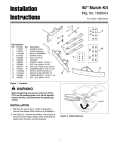
Attachment
Illustrated
Parts List
Attachment
Mfg. No.
Description
1694947
Lift Lever Kit
MANUFACTURING, INC.
500 N. Spring Street / PO Box 997
Port Washington, WI 53074-0997 USA
www.simplicitymfg.com
© Copyright 2007 Simplicity Manufacturing, Inc. All Rights Reserved. Printed In USA.
Part No.: 1734852
Rev. 04/2007
TP 400-4568-00-AT-SMA
Table Of Contents
PRODUCT COMPONENTS
PAGES
Lift Lever Kit .........................................................................................................................................................
4
Torque Specification Chart ..................................................................... Inside Back Cover
Lift Lever Kit
987175
NOTE: Unless noted otherwise,
use the standard hardware torque
specification chart.
The above parts group applies to the following Mfg. Nos.:
1694947 - Lift Lever Kit
Briggs and Stratton Yard Power Products Group
Copyright © 2007 by Briggs and Stratton Corporation
Milwaukee, WI, USA. All rights reserved
4
TP 400-4568-00-AT-SMA
Lift Lever Kit
REF NO PART NO.
1
2
3
4
5
6
7
8
9
10
11
12
13
14
15
16
17
18
19
20
21
1725959ASM
1960033SM
1723124SM
1713995SM
1960674SM
1723321SM
1725958SM
1721999ASM
1960126SM
1727441ASM
1927609SM
1931277SM
1708298SM
1732511ASM
1960074SM
1960585SM
1725957SM
2826149SM
1960636SM
1731381ASM
1921221SM
QTY. DESCRIPTION
1
1
1
1
1
1
1
1
1
1
1
6
2
1
2
2
2
3
3
1
1
ROD & TUBE ASSEMBLY
CLIP, Hair Pin
BUTTON, Red
GRIP, Soft, Black
PUSH NUT, 1/4
SPRING, Compression
ROD, Latch
LATCH, Lift Lever
PUSH NUT, 1/4
LEVER ASSEMBLY
PIN, 3/8 x 1
NUT, Hex, Flange Whiz Lock, 5/16-18
PIN, Round Head, Drilled, 3/8 x 1
BRACKET, Mounting
CLIP, Hair Pin
CAPSCREW, Hex Head, 5/16-18 x 1-3/4
PAD, Rubber
CAPSCREW, Hex Head, 5/16-18 x 1
NUT, Hex, KEPS, 5/16-18
SHAFT ASSEMBLY
CAPSCREW, Hex Head, 5/16-18 x 1-1/2
Footnotes
The above parts group applies to the following Mfg. Nos.:
1694947 - Lift Lever Kit
Briggs and Stratton Yard Power Products Group
Copyright © 2007 by Briggs and Stratton Corporation
Milwaukee, WI, USA. All rights reserved
5
TP 400-4568-00-AT-SMA
Hardware Identification & Torque Specifications
Common Hardware Types
Torque Specification Chart
Hex Head Capscrew
FOR STANDARD MACHINE HARDWARE (Tolerance ± 20%)
Washer
Hardware
Grade
Lockwasher
Carriage Bolt
No
Marks
SAE Grade 2
Hex Nut
Size Of
Hardware
Standard Hardware Sizing
8-32
8-36
10-24
10-32
1/4-20
1/4-28
5/16-18
5/16-24
3/8-16
3/8-24
7/16-14
7/16-20
1/2-13
1/2-20
9/16-12
9/16-18
5/8-11
5/8-18
3/4-10
3/4-16
7/8-9
7/8-14
1-8
1-12
When a washer or nut is identified as 1/2”, this is the
Nominal size, meaning the inside diameter is 1/2 inch; if a
second number is present it represent the threads per inch
When bolt or capscrew is identified as 1/2 - 16 x 2”, this
means the Nominal size, or body diameter is 1/2 inch; the
second number represents the threads per inch (16 in this
example, and the final number is the body length of the
bolt or screw (in this example 2 inches long).
The guides and ruler furnished below are designed to
help you select the appropriate hardware and tools.
0
1/4
Nut, 1/2”
1/2
Inside
Diameter
3/4
1
1/4
1/2
3/4
Screw, 1/2 x 2
2
1/4
Body
Diameter
in/lbs
ft/lbs
19
20
27
31
66
76
11
12
20
23
30
35
50
55
65
75
90
100
160
180
140
155
220
240
Nm.
2.1
2.3
3.1
3.5
7.6
8.6
15.0
16.3
27.2
31.3
40.8
47.6
68.0
74.8
88.4
102.0
122.4
136
217.6
244.8
190.4
210.8
299.2
326.4
SAE Grade 5
in/lbs
ft/lbs
30
31
43
49
8
10
17
19
30
35
50
55
75
90
110
120
150
180
260
300
400
440
580
640
SAE Grade 8
Nm.
in/lbs
ft/lbs
Nm.
3.4
3.5
4.9
5.5
10.9
13.6
23.1
25.8
40.8
47.6
68.0
74.8
102.0
122.4
149.6
163.2
204.0
244.8
353.6
408.0
544.0
598.4
788.8
870.4
41
43
60
68
12
14
25
27
45
50
70
80
110
120
150
170
220
240
386
420
600
660
900
1,000
4.6
4.9
6.8
7.7
16.3
19.0
34.0
34.0
61.2
68.0
95.2
108.8
149.6
163.2
204.0
231.2
299.2
326.4
525.0
571.2
816.0
897.6
1,244.0
1,360.0
NOTES
1. These torque values are to be used for all hardware
excluding: locknuts, self-tapping screws, thread forming
screws, sheet metal screws and socket head setscrews.
2. Recommended seating torque values for locknuts:
a. for prevailing torque locknuts - use 65% of grade 5
torques.
b. for flange whizlock nuts and screws - use 135% of
grade 5 torques.
3. Unless otherwise noted on assembly drawings, all torque
values must meet this specification.
1/2
Body
Length
3/4
3
1/4
1/2
3/4
4
Wrench & Fastener Size Guide
1/4
5/16
3/8
1/4” Bolt or Nut
Wrench—7/16”
5/16” Bolt or Nut
Wrench—1/2”
3/8” Bolt or Nut
Wrench—9/16”
7/16
DIA.
7/16” Bolt or Nut
Wrench (Bolt)—5/8”
Wrench (Nut)—11/16”
1/2
DIA.
1/2” Bolt or Nut
Wrench—3/4”