1
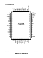
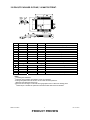
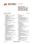
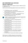
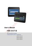
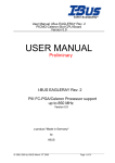
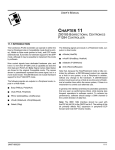
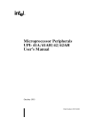
LPC47S45x Advanced I/O with X-Bus Interface FEATURES 2.88MB Super I/O Floppy Disk Controller - Licensed CMOS 765B Floppy Disk Controller - Software and Register Compatible with SMSC's Proprietary 82077AA Compatible Core - Configurable Open Drain/Push-Pull Output Drivers - Supports Vertical Recording Format - 16-Byte Data FIFO - 100% IBM Compatibility - Detects All Overrun and Underrun Conditions - Sophisticated Power Control Circuitry (PCC) Including Multiple Powerdown Modes for Reduced Power Consumption - DMA Enable Logic - Data Rate and Drive Control Registers - 480 Address, up to 15 IRQ and Four DMA Options Enhanced Digital Data Separator - 2 Mbps, 1 Mbps, 500 Kbps, 300 Kbps, 250 Kbps Data Rates - Programmable Precompensation Modes Keyboard Controller - 8042 Software Compatible - 8-Bit Microcomputer - 2k Bytes of Program ROM - 256 Bytes of Data RAM - Four Open Drain Outputs Dedicated for Keyboard/Mouse Interface - Asynchronous Access to Two Data Registers and One Status Register - Supports Interrupt and Polling Access - 8-Bit Counter Timer - Port 92 Support - Fast Gate A20 and KRESET Outputs Serial Ports - Two Full Function Serial Ports - High Speed NS16C550A Compatible UARTs with Send/Receive 16-Byte FIFOs - Supports 230k and 460k Baud - Programmable Baud Rate Generator - Modem Control Circuitry - 480 Address and 15 IRQ Options - IrDA 1.0, HP-SIR, ASK IR Support 3.3 Volt Operation (5V tolerant) Floppy Disk Controller (Supports 2 FDCs) Multi-Mode Parallel Port Two UARTs 8042 Keyboard Controller SMBus Controller - SMBus access to LCD Interface - SMBus Serial Port 2 Interface Disable - SMBus access to Power On Elapsed Time Counters - Programmable Slave Address X-Bus Interface - Supports up to four external I/O components - Offers two modes of operation - Support for Driving LCD Panel Interface Controller - Supports Port 80h “Snooping” Programmable Wakeup Event Interface (IO_PME# Pin) SMI Support (IO_SMI# Pin) GPIOs (55) Fan Controller - One Fan Speed Control Output - One Fan Tachometer Input ISA IRQ to Serial IRQ Conversion XNOR Chain for Board Test Mode PC2001 and ACPI 2.0 Compliant 128-pin QFP Package ISA Plug-and-Play Compatible Register Set Intelligent Auto Power Management Power On Elapsed Time Counters - Counter for Main Power - Counter for Standby Power Real Time Clock - MC146818 and DS1287 Compatible - 256 Bytes of Battery Backed CMOS in Two 128Byte Banks - 128 Bytes of CMOS RAM Lockable in 4x32 Byte Blocks - 12 and 24 Hour Time Format - 24-hour daily alarm - 30-day alarm - Binary and BCD Format - <1µA Standby Current (typ) SMSC LPC47S45x 1 PRODUCT PREVIEW Rev. 04-30-07 Multi-Mode Parallel Port with ChiProtect - Standard Mode IBM PC/XT, PC/AT, and PS/2 Compatible Bi-directional Parallel Port - Enhanced Parallel Port (EPP) Compatible - EPP 1.7 and EPP 1.9 (IEEE 1284 Compliant) - IEEE 1284 Compliant Enhanced Capabilities Port (ECP) - ChiProtect Circuitry for Protection Against Damage Due to Printer Power-On - 960 Address, up to 15 IRQ and Four DMA Options Pin Reduced ISA Host Interface (LPC Bus) - Multiplexed Command, Address and Data Bus - 8-Bit I/O Transfers - 8-Bit DMA Transfers - 16-Bit Address Qualification - Serial IRQ Interface Compatible with Serialized IRQ Support for PCI Systems - Power Management Event (PME) Interface Pin Power Management ACPI Registers ORDERING INFORMATION LPC47S457-NS for 128 pin QFP package with Phoenix 42i Keyboard BIOS Lead-Free RoHS Compliant LPC47S457-NC for 128 pin QFP package with Phoenix 42i Keyboard BIOS 80 ARKAY DRIVE, HAUPPAUGE, NY 11788 (631) 435-6000, FAX (631) 273-3123 Copyright © 2007 SMSC or its subsidiaries. All rights reserved. Circuit diagrams and other information relating to SMSC products are included as a means of illustrating typical applications. Consequently, complete information sufficient for construction purposes is not necessarily given. Although the information has been checked and is believed to be accurate, no responsibility is assumed for inaccuracies. SMSC reserves the right to make changes to specifications and product descriptions at any time without notice. Contact your local SMSC sales office to obtain the latest specifications before placing your product order. The provision of this information does not convey to the purchaser of the described semiconductor devices any licenses under any patent rights or other intellectual property rights of SMSC or others. All sales are expressly conditional on your agreement to the terms and conditions of the most recently dated version of SMSC's standard Terms of Sale Agreement dated before the date of your order (the "Terms of Sale Agreement"). The product may contain design defects or errors known as anomalies which may cause the product's functions to deviate from published specifications. Anomaly sheets are available upon request. SMSC products are not designed, intended, authorized or warranted for use in any life support or other application where product failure could cause or contribute to personal injury or severe property damage. Any and all such uses without prior written approval of an Officer of SMSC and further testing and/or modification will be fully at the risk of the customer. Copies of this document or other SMSC literature, as well as the Terms of Sale Agreement, may be obtained by visiting SMSC’s website at http://www.smsc.com. SMSC is a registered trademark of Standard Microsystems Corporation (“SMSC”). Product names and company names are the trademarks of their respective holders. SMSC DISCLAIMS AND EXCLUDES ANY AND ALL WARRANTIES, INCLUDING WITHOUT LIMITATION ANY AND ALL IMPLIED WARRANTIES OF MERCHANTABILITY, FITNESS FOR A PARTICULAR PURPOSE, TITLE, AND AGAINST INFRINGEMENT AND THE LIKE, AND ANY AND ALL WARRANTIES ARISING FROM ANY COURSE OF DEALING OR USAGE OF TRADE. IN NO EVENT SHALL SMSC BE LIABLE FOR ANY DIRECT, INCIDENTAL, INDIRECT, SPECIAL, PUNITIVE, OR CONSEQUENTIAL DAMAGES; OR FOR LOST DATA, PROFITS, SAVINGS OR REVENUES OF ANY KIND; REGARDLESS OF THE FORM OF ACTION, WHETHER BASED ON CONTRACT; TORT; NEGLIGENCE OF SMSC OR OTHERS; STRICT LIABILITY; BREACH OF WARRANTY; OR OTHERWISE; WHETHER OR NOT ANY REMEDY OF BUYER IS HELD TO HAVE FAILED OF ITS ESSENTIAL PURPOSE, AND WHETHER OR NOT SMSC HAS BEEN ADVISED OF THE POSSIBILITY OF SUCH DAMAGES. SMSC LPC47S45x 2 PRODUCT PREVIEW Rev. 04-30-07 GENERAL DESCRIPTION The LPC47S45x is a 3.3V PC2001 compliant Super I/O controller designed for server applications. The LPC47S45x implements the LPC interface, a pin reduced ISA interface which provides the same or better performance as the ISA/X-bus with a substantial savings in pins used. The part provides 55 GPIO pins, ACPI support, an X-Bus interface, two SMBus controllers, a fan speed control output, a fan tachometer input and four ISA IRQs that can be routed to any of the serial IRQs. The LPC47S45x also provides Power on Elapsed Time counters for Main Power and Standby Power, power supply on/off control, and a Real Time Clock. The X-Bus interface allows the LPC47S45x to interface to as many as four external components that have an eight bit data bus and occupy up to 4 contiguous I/O address ports. It is accessible by either the SMBus or the LPC interface. It is capable of interfacing to an LCD Panel Interface Controller without any external logic and it can be used for Port 80h “snooping”. The LPC47S45x offers two SMBus controllers that share the same pin interface. The SMBus slave only device provides external access to an LCD controller that can be attached to the X-Bus. It is capable of disabling the floppy port, the serial ports, and the parallel port. The SMBus slave only device can also tristate the Serial Port 2 interface so that it may be muxed with an external UART controller. The LPC47S45x is equipped with two counters that may be monitored either by the SMBus slave only device or by the LPC interface, which monitor the length of time VCC and VTR are active. The LPC47S45x incorporates a keyboard interface, SMSC's true CMOS 765B floppy disk controller, advanced digital data separator, two 16C550 compatible UARTs, one Multi-Mode parallel port which includes ChiProtect circuitry plus EPP and ECP, and Intelligent Power Management. The true CMOS 765B core provides 100% compatibility with IBM PC/XT and PC/AT architectures in addition to providing data overflow and underflow protection. The SMSC advanced digital data separator incorporates SMSC's patented data separator technology, allowing for ease of testing and use. The on-chip UARTs are compatible with the NS16C550. The parallel port is compatible with IBM PC/AT architecture, as well as IEEE 1284 EPP and ECP. The LPC47S45x incorporates sophisticated power control circuitry (PCC). The PCC supports multiple low power down modes. The LPC47S45x supports the ISA Plug-and-Play Standard (Version 1.0a) and provides the recommended functionality to support Windows 2000, Windows Me, and PC2001. The I/O Address, DMA Channel and Hardware IRQ of each logical device in the LPC47S45x may be reprogrammed through the internal configuration registers. There are 480 I/O address location options, a Serialized IRQ interface, and three DMA channels. SMSC LPC47S45x 3 PRODUCT PREVIEW Rev. 04-30-07 128 127 126 125 124 123 122 121 120 119 118 117 116 115 114 113 112 111 110 109 108 107 106 105 104 103 nPS_ON nPB_IN CLKO40 VTR XOSEL XD7/GP17 XD6/GP16 XD5/GP15 XD4/GP14 XD3/GP13 XD2/GP12 XD1/GP11 XD0/GP10 LCDCS XCS1/GP77 nXCS0/GP76 XA3/GP75 XA2/GP74 XA1/GP73 XA0/GP72 nXRD/GP71 nXWR/GP70 VSS SDAT SCLK GP57/nDTR2/SADR1 PIN CONFIGURATION 1 2 3 4 5 6 7 8 9 10 11 12 13 14 15 16 17 18 19 20 21 22 23 24 25 26 27 28 29 30 31 32 33 34 35 36 37 38 LPC47S45x 128 PIN QFP 102 101 100 99 98 97 96 95 94 93 92 91 90 89 88 87 86 85 84 83 82 81 80 79 78 77 76 75 74 73 72 71 70 69 68 67 66 65 GP56/nCTS2 GP55/nRTS2/SADR0 GP54/nDSR2 GP53/TXD2/IRTX GP52/RXD2/IRRX GP51/nDCD2 VCC GP50/nRI2 nDCD1 nRI1 nDTR1 nCTS1 nRTS1 nDSR1 TXD1 RXD1 nSTROBE nALF nERROR nACK BUSY PE SLCT VSS PD7 PD6 PD5 PD4 PD3 PD2 PD1 PD0 nSLCTIN nINIT VCC GP37/A20M GP36/nKBDRST GP35/IRQINB GP84 GP85 GP86 GP87 GP62/IRQINC GP20/P17/DS1# GP21/P16 GP22/P12/MTR1# GP23/IRQIND GP24/P17 GP25/P12 GP26/SYSOPT GP60/LED1 GP61/LED2 GP27/IO_SMI# GP30/nXCS2 GP31/nXCS3 VTR GP32/FAN_TACH GP33/FAN KDAT KCLK MDAT MCLK VSS GP34/IRQINA 39 40 41 42 43 44 45 46 47 48 49 50 51 52 53 54 55 56 57 58 59 60 61 62 63 64 VTR Vbat XTAL1 XTAL2/CLKI32 AVSS GP40/DRVDEN0 GP41/DRVDEN1 MTR0# DSKCHG# DS0# DIR# STEP# WDATA# WGATE# HDSEL# INDEX# TRK0# WRTPRT# RDATA# GP42/IO_PME# VCC CLOCKI LAD0 LAD1 LAD2 LAD3 LFRAME# LDRQ# PCI_RESET# LPCPD# GP43/DDRC PCI_CLK SER_IRQ VSS GP80 GP81 GP82 GP83 SMSC LPC47S45x 4 PRODUCT PREVIEW Rev. 04-30-07 128 PIN QFP PACKAGE OUTLINE, 3.9 MM FOOTPRINT. A A1 A2 D D1 E E1 H L L1 e θ W R1 R2 ccc MIN ~ 0.05 2.55 23.70 19.90 17.70 13.90 0.09 0.73 ~ 0o 0.10 0.13 0.13 ~ NOMINAL ~ ~ ~ ~ ~ ~ ~ ~ 0.88 1.95 0.50 Basic ~ ~ ~ ~ ~ MAX 3.4 0.5 3.05 24.10 20.10 18.10 14.10 0.20 1.03 ~ REMARKS Overall Package Height Standoff Body Thickness X Span X body Size Y Span Y body Size Lead Frame Thickness Lead Foot Length Lead Length Lead Pitch Lead Foot Angle Lead Width Lead Shoulder Radius Lead Foot Radius Coplanarity 7o 0.30 ~ 0.30 0.08 Notes: Controlling Unit: millimeter. 2 Tolerance on the position of the leads is ± 0.04 mm maximum. 3 Package body dimensions D1 and E1 do not include the mold protrusion. Maximum mold protrusion is 0.25 mm. 4 Dimension for foot length L measured at the gauge plane 0.25 mm above the seating plane. 5 Details of pin 1 identifier are optional but must be located within the zone indicated. 1 SMSC LPC47S45x 5 PRODUCT PREVIEW Rev. 04-30-07