1
USER’S MANUAL
V390 Semi Recumbent Bike
USER WEIGHT LIMITATION: 300lbs(136kgs)
SERIAL NUMBER (found on frame):
2
V 390 SEMI-RECUMBENT BIKE
PRECAUTIONS
For future service or related questions:
Please staple your receipt and/or write in the name and phone number of the retail store where you purchased your bike.
Name: ______________________________ Phone Number: ___________________ Receipt: ______________________
Precautions:
WARNING:
To reduce the risk of burns, fire, electric shock, or injury to persons, read the following important precautions
and information before operating the bike. It is the responsibility of the owner to ensure that all users of this bike are adequately
informed of all warnings and precautions.
•
Use the bike only as described in this manual.
•
Place on a level surface. Do not place the bike on any surface that blocks air openings. To protect the floor or carpet from
damage, place a mat under the bike.
•
When choosing a location for the bike be sure that the location and position permit access to a plug.
•
Keep the bike indoors, away from moisture and dust. Do not put the bike in a garage or covered patio, or near water.
•
Do not operate the bike where aerosol products are used or where oxygen is being administered.
•
Keep children under the age of 12 and pets away from the bike at all times.
•
The bike should not be used by persons weighing more than 300LBS (136 Kgs).
•
Never allow more than one person on the bike at a time. Wear appropriate exercise clothing when using the bike. Do not
wear loose clothing that could become caught in the bike. Athletic support clothes are recommended for both men and
women. Always wear athletic shoes. Never use the bike with bare feet, wearing only stockings, or in sandals.
•
When connecting the power cord, plug the power cord into a grounded circuit.
•
Always examine your bike before using to ensure all parts are in working order.
•
Allow the bike to come to a full stop before stepping off.
•
Never insert any object or body parts into any opening.
•
Follow the safety information in regards to plugging in your bike.
•
The item is suitable for semi-commercial, light-commercial and home usage.
•
Keep the power cord away from the incline wheels and do not run the power cord underneath your bike. Do not operate
the bike with a damaged or frayed power cord.
•
Always unplug the bike before cleaning and/or servicing. Service to your bike should only be performed by an authorized
service representative, unless authorized and/or instructed by the manufacturer. Failure to follow these instructions will
void the bike warranty.
www.smoothfitness.com
3
PRECAUTIONS
Pour réparations futures ou questions connexes :
Please staple your receipt and/or write in the name and phone number of the retail store where you purchased your bike.
Name: ______________________________ Phone Number: ___________________ Receipt: ______________________
AVERTISSEMENT : Pour réduire le risque de brûlures, d'incendie, d'électrocution ou de blessures, lire les précautions
suivantes et informations importantes avant d'utiliser le vélo. Il est de la responsabilité du propriétaire de s'assurer
que tous les utilisateurs de ce vélo sont correctement informés de tous les avertissements et les précautions.
•
•
•
•
•
•
•
•
Utilisez le vélo uniquement comme décrit dans ce manuel.
Placez-le sur une surface plane. Ne pas placer la moto sur une surface qui bloque les ouvertures d'air. Afin de
protéger le plancher ou le tapis de tout dommage, placez un tapis sous la moto.
Lorsque vous choisissez un emplacement pour le vélo être sûr que l'emplacement et la position de permettre
l'accès à un bouchon.
Gardez le vélo de l'intérieur, loin de l'humidité et la poussière. Ne pas mettre la moto dans un garage ou un
patio couvert, ou près de l'eau.
Ne pas faire fonctionner la moto où des produits aérosols sont utilisés et où l'oxygène est administré.
Gardez les enfants sous l'âge de 12 ans et les animaux loin de la moto à tout moment.
Le vélo ne doit pas être utilisé par des personnes pesant plus de 300lbs (136 kg).
Ne laissez jamais plus d'une personne sur le vélo à la fois. Porter des vêtements exercice approprié lors de
l'utilisation du vélo. Ne portez pas de vêtements amples qui pourraient se coincer dans le vélo. Les
vêtements de support sont recommandés pour les hommes et les femmes. Portez toujours des chaussures
de sport. Ne jamais utiliser le vélo avec les pieds nus, porter des bas seulement, ou en sandales..
•
•
Lorsque vous branchez le cordon d'alimentation, branchez le cordon d'alimentation dans un circuit à la terre.
Toujours examiner votre vélo avant de l'utiliser pour s'assurer que toutes les pièces sont en ordre de marche.
•
•
•
Laisser le vélo à venir à un arrêt complet avant ma descente.
Ne jamais insérer d'objet ou le corps des pièces dans les ouvertures.
Suivez les consignes de sécurité en ce qui concerne le branchement de votre vélo
•
Gardez le cordon d'alimentation loin des roues pente et ne pas courir le cordon d'alimentation en dessous de
votre vélo. Ne pas faire fonctionner la moto avec un cordon d'alimentation endommagé ou effiloché.
Débranchez toujours le vélo avant de le nettoyer et / ou d'entretien. Service pour votre moto ne doit être
effectuée par un représentant de service autorisé, sauf autorisation et / ou les instructions du fabricant. Le
non respect de ces instructions annule la garantie de vélo
•
4
V 390 SEMI-RECUMBENT BIKE
POWER REQUIREMENTS
Power Requirements:
IMPROPER CONNECTION OF THE EQUIPMENT GROUNDING CONNECTOR CAN RESULT IN THE RISK OF AN ELECTRIC
SHOCK. CHECK WITH A QUALIFIED ELECTRICIAN OR SERVICE MAN IF YOU ARE IN DOUBT AS TO WHETHER THE
PRODUCT IS PROPERLY GROUNDED. DO NOT MODIFY THE PLUG PROVIDED WITH THE PRODUCT, IF IT WILL NOT FIT
THE OUTLET; HAVE A PROPER OUTLET INSTALLED BY A QUALIFIED ELECTRICIAN.
This bike can be seriously damaged by sudden voltage changes in your home’s electrical power. Voltage spikes, surges and noise
interference can result from weather conditions or from other appliances being turned on or off. To reduce the possibility of bike
damage, always use a surge protector (not included) with your bike.
Surge protectors can be purchased at most hardware stores. The manufacturer recommends a single outlet surge protector with a
UL 1449 rating as a Transient Voltage Surge Suppressor (TVSS) with a UL suppressed voltage rating of 400V or less and an
electrical rating 120VAC, 15 amps.
This bike must be grounded to reduce the risk of electrical shock. Grounding provides a path of least resistance for electric current,
should the bike malfunction. This bike is equipped with an electrical cord that has an equipment-grounding conductor and a
grounding plug. Always plug the power cord into a surge protector, and plug the surge protector into an appropriate outlet that is
properly installed and grounded in accordance with all local codes and ordinances.
Alimentation :
UN MAUVAIS BRANCHEMENT DU CONNECTEUR DE MISE À LA TERRE DE L’ÉQUIPEMENT POURRAIT PROVOQUER UN
CHOC ÉLECTRIQUE. EN CAS DE DOUTE, CONSULTER UN ÉLECTRICIEN OU UN RÉPARATEUR QUALIFIÉ POUR SAVOIR
SI LE PRODUIT EST CORRECTEMENT MIS À LA TERRE. NE PAS MODIFIER LA FICHE FOURNIE AVEC LE PRODUIT. SI
ELLE N’ENTRE PAS DANS LA PRISE, FAIRE INSTALLER UNE PRISE APPROPRIÉE PAR UN ÉLECTRICIEN
PROFESSIONNEL.
Ce tapis roulant pourrait être gravement endommagé en cas de changement soudain de tension dans votre alimentation électrique.
Les conditions météorologiques ou la mise sous tension ou hors tension d’autres appareils électriques peuvent provoquer des
pointes de tension, des surtensions ou un brouillage. Pour réduire la possibilité que le tapis soit endommagé, toujours utiliser un
limiteur de surtension (non inclus) avec votre tapis roulant.
Il est possible d’acheter des limiteurs de surtension dans la plupart des quincailleries. Le fabricant recommande un limiteur de
surtension UL 1449 à prise unique comme suppresseur de tension transitoire (TVSS) ayant un taux de suppression de tension de
400 V ou moins et une tension électrique de 110 V C.A., 15 A.
Ce tapis roulant doit être mis à la terre pour réduire le risque de choc électrique. La mise à la terre fournit une voie de moindre
résistance au courant électrique en cas de mauvais fonctionnement du tapis roulant. Ce tapis roulant est équipé d’un cordon
électrique avec un conducteur de mise à la terre et une fiche de mise à la terre. Brancher toujours le cordon électrique dans un
limiteur de surtension et brancher le limiteur de surtension dans une prise appropriée, correctement installée et mise à la terre
conformément à tous les codes locaux et ordonnances.
www.smoothfitness.com
5
BEFORE YOU BEGIN
Open the boxes:
Open the boxes of your new equipment. Inventory all parts included in the boxes, and Supplied Hardware lists
on pages 7 for a full count of the parts included. If you are missing any parts or have any questions contact us
directly at 888-800-1167
Gather your tools:
Before you begin, make sure that you have gathered all the necessary tools you may require to assemble the unit
properly. Having all of the necessary equipment at hand will save time and make the assembly quick and hassle-free.
Clear your work area:
Make sure that you have cleared away a large enough space to properly assemble the unit. Make sure the space is
free from anything that may cause injury during assembly. After the unit is fully assembled, make sure there is a
comfortable amount of free area around the unit for unobstructed operation.
Invite a friend:
Some of the assembly steps may require heavy lifting. It is recommended that you obtain the assistance of another
person when assembling this product.
User Weight Limitation:
Please note that there is a weight limitation for this product. If you weigh more than 300LBS (Approx. 136 Kgs). It is
not recommended that you use this product. Serious injury may occur if the user’s weight exceeds the limit shown
here. This product is not intended to support users whose weight exceeds this limit.
Care and maintenance:
The safety level can be maintained only if it is examined for damage and wear.
Replace any defective components immediately and stop all use of the equipment until repaired.
Always take care when mounting the equipment. Straddle the equipment by placing your feet on the straddle rails.
Dismount from the equipment only after all parts have stopped.
Always check the wear and tear components like pulley, belts, etc.…To prevent injury.
6
V 390 SEMI-RECUMBENT BIKE
SUPPLIED COMPONENTS / SUPPLIED HARDWARE
This list identifies the major components you will use to assemble this product.
Console Upper Cover
Console Bottom Cover
Console Sleeve
Upright Post Assembly &
Water Bottle Bracket
Front Small Handlebar
Upright Sleeve
Seat Cushion
Mesh Backrest & Mesh
Backrest Cover
Rail Decoration Cover
Square Stopper,
Hex Head Bolt & Nut (M8)
Pedal
Front Stabilizer
Seat Handlebar Assembly
Seat Frame
adjusting Handle
Rear Stabilizer
Seat Carriage Assembly
Main Frame Assembly & Leveler
Pull Bar & Fixed Bracket
for Seat Rail
www.smoothfitness.com
7
SUPPLIED COMPONENTS / SUPPLIED HARDWARE
This list identifies the major components you will use to assemble this product.
NOTICE: The length of all bolts and screws except those with flat heads is
Measured from below the head to the end of the bolt or screw. Flat head
bolts and screws are measured from the top of the head to the end of
the
bolt or screw
After unpacking the unit, you will notice that the package includes 3 bags of hardware (HARDWARE KIT A,
HARDWARE KIT B and HARDWARE KIT C).
Assembly’s Step 1: Using HARDWARE KIT A
Assembly’s Step 2, 4: Using HARDWARE KIT B
Assembly’s Step 7 ~ 9: Using HARDWARE KIT C
Note:
a. Please review below to know the content of each hardware kit (A, B and C)
b. Some small parts may have been pre-attached for shipping. If a part is not in the hardware bag, check to see if it has
been pre-assembled
Part No. and Description
Q’TY
HARDWARE KIT A
HARDWARE KIT B
88 Lock Washer (M8)
4 pcs
90 Washer (8x16x2.0t)
4 pcs
115 Bolt, Socket Head (M8xp1.25x90mm)
4 pcs
Part No. and Description
Q’TY
88 Lock Washer (M8)
5 pcs
90 Washer (8x16x2.0t)
5 pcs
97 Screw, Pan Head (M5xp0.8x25mm)
4 pcs
8
V 390 SEMI-RECUMBENT BIKE
SUPPLIED COMPONENTS / SUPPLIED HARDWARE
This list identifies the major components you will use to assemble this product.
HARDWARE KIT B
HARDWARE KIT C
Part No. and Description
Q’TY
99 Screw, Round Head (M5xp0.8x15mm)
4 pcs
111 Bolt, Socket Head (M6xp1.0x15mm)
112 Bolt, Socket Head (M8xp1.25x16mm)
114 Bolt, Socket Head (M8xp1.25x55mm)
Part No. and Description
4 pcs
4 pcs
1 pcs
Q’TY
88 Lock Washer (M8)
10 pcs
90 Washer (8x16x2.0t)
10 pcs
93 Self-Tapping Screw, Truss Head (M4x16mm)
1 pc
99 Screw, Round Head (M5xp0.8x15mm)
2 pcs
107 Carriage Bolt (M8xp1.25x50mm)
2 pcs
112 Bolt, Socket Head (M8xp1.25x16mm)
113 Bolt, Socket Head (M8xp1.25x40mm)
10 pcs
4 pcs
119 Bolt, Hex Head (M10xp1.5x90mm)
1 pc
127 Nylock Nut (M8)
128 Thin Nylock Nut (M10xp1.5)
2 pcs
1 pc
THE FOLLOWING TOOLS ARE INCLUDED FOR ASSEMBLY:
MULTI WRENCH TOOL W/
PHILLIPS SCREWDRIVER
(13 & 15mm)
HEX WRENCH
(17mm x 2 pcs)
ALLEN WRENCH
(5 & 6 mm)
www.smoothfitness.com
COMPLETE PARTS LIST
NO.
V390-1
V390-2
V390-3
V390-4
V390-5
V390-6
V390-7
V390-8
V390-9
V390-10
V390-11
V390-12
V390-13
V390-14
V390-15
V390-16
V390-17
V390-18
V390-19
V390-20
V390-21
V390-22
V390-23
V390-24
V390-25
V390-26
V390-27
V390-28
V390-29
V390-30
V390-31
V390-32
V390-33
V390-34
V390-35
V390-36
V390-37
Item Name
Main Frame
Front Seat Support Bracket
Inner Seat Carriage Slider
Outer Seat Carriage Slider
Front Stabilizer
Rear Stabilizer
Upright Post
Front Small Handlebar
Seat Carriage
Seat Fixed Stand
Seat Frame
Seat Handlebar
Front Left Chain Cover
Front Right Chain Cover
Crank Cover (L&R)
Rear Left Chain Cover
Rear Right Chain Cover
Decoration Cover for Carriage Slider
Connection Cover
Left Pedal
Right Pedal
Pulley
Magnet
Belt
Pressure Wheel
Bushing (ψ50.8xψ10)
Bushing (ψ60xψ10)
Slider Sleeve
Pull Bar
Tube Decoration Cover for Stabilizer
Transprtation Wheel (L&R)
Front Stabilizer End Cap
Adjusting Rear Stabilizer End Cap
Upright Sleeve
Foam Grip (530mm)
Square Plug (20x40mm)
Console Upper Cover
Q'TY
1
1
1
1
1
1
1
1
1
1
1
1
1
1
2
1
1
1
1
1
1
1
1
1
1
2
4
1
1
2
2
2
2
1
2
1
1
9
10
V 390 SEMI-RECUMBENT BIKE
COMPLETE PARTS LIST
NO.
V390-38
V390-39
V390-40
V390-41
V390-42
V390-43
V390-44
V390-45
V390-46
V390-47
V390-48
V390-49
V390-50
V390-51
V390-52
V390-53
V390-54
V390-55
V390-56
V390-57
V390-58
V390-59
V390-60
V390-61
V390-62
V390-63
V390-64
V390-65
V390-66
V390-68
V390-69
V390-70
V390-71
V390-72
V390-73
V390-74
V390-75
Item Name
Console Bottom Cover
Left Console Sleeve
Right Console Sleeve
Mesh Backrest
Seat Cushion
Foam Grip (330mm)
Hand Pulse Sensor (L&R)
Round Plug (31.8mm)
Tube Plug (25.4mm)
Locking Bar
Left Seat Carriage Cover
Right Seat Carriage Cover
Adjusting Handle
Seat Fixed Wheel
Roller (37.6mm)
Square Stopper
Left Rail Decoration Cover
Right Rail Decoration Cover
Flywheel
Cable
Fixed Bracket for Motor
Left Crank
Right Crank
Axle for Crank
Fixed Bracket for Idler
Upright Cover (L&R)
Seat Rail
Fixed Bracket for Seat Rail
Adjusting Handle Stand
Fixing Pin
Axle for Sliding Track
Axle for Braking
Axle for Backrest Tube
Bearing (6004zz)
Eye Bolt (40mm)
Eye Bolt (50mm)
Tension Bracket
Q'TY
1
1
1
1
1
2
2
4
4
1
1
1
1
1
4
4
1
1
1
1
1
1
1
1
1
2
1
1
1
1
1
1
1
2
2
3
2
www.smoothfitness.com
COMPLETE PARTS LIST
NO.
V390-76
V390-77
V390-78
V390-79
V390-80
V390-81
V390-82
V390-83
V390-84
V390-85
V390-86
V390-88
V390-89
V390-90
V390-91
V390-92
V390-93
V390-94
V390-95
V390-96
V390-97
V390-98
V390-99
V390-100
V390-101
V390-102
V390-103
V390-104
V390-105
V390-106
V390-107
V390-108
V390-109
V390-111
V390-112
V390-113
V390-114
Item Name
Bushing (10.2x14x2mm)
Bushing (10.2x14x10mm)
Idler Spring
Spring for Seat Fixed Stand
Spring for Fixing Pin
Spring for Adjusting Handle Stand
Bushing for Seat Fixed Wheel
Screw Cap
Bushing (8x12x6.5mm)
C Ring (20mm)
Wave Washer
Lock Washer (M8)
Washer (6x19x1.5t)
Washer (8x16x2.0t)
Washer (10x23x2.0t)
Washer (21x30x1.0t)
Self-Tapping Screw, Truss Head (M4x16mm)
Self-Tapping Screw, Truss Head (M5x18mm)
Self-Tapping Screw, Flat Head (M4x20mm)
Bolt, Button Head (M6xp1.0x40mm)
Screw, Pan Head (M5xp0.8x25mm)
Screw, Round Head (1/4’’x20mm)
Nylon-Coated Screw, Round Head (M5xp0.8x15mm)
Screw, Round Head (M5xp0.8x40mm)
Bolt, Round Head (M6xp1.0x25mm)
Bolt, Round Head (M6xp1.0x35mm)
Bolt, Round Head (M6xp1.0x65mm)
Screw, Flat Head (M5xp0.8x12mm)
Bolt, Pan Head (M8xp1.25x15mm)
Bolt, Pan Head (M8xp1.25x25mm)
Carriage Bolt (M8xp1.25x50mm)
Bolt, Button Head (M10xp1.25x35mm)
Bolt, Hex Head (M10xp1.25x45mm)
Bolt, Socket Head (M6xp1.0x15mm)
Bolt, Socket Head (M8xp1.25x16mm)
Bolt, Socket Head (M8xp1.25x40mm)
Bolt, Socket Head (M8xp1.25x55mm)
Q'TY
1
1
1
1
1
1
2
2
4
1
1
23
2
25
3
2
9
27
2
2
4
4
14
2
8
2
1
4
2
4
2
1
1
4
14
4
1
11
12
V 390 SEMI-RECUMBENT BIKE
COMPLETE PARTS LIST
NO.
V390-115
V390-116
V390-117
V390-118
V390-119
V390-120
V390-121
V390-122
V390-123
V390-124
V390-125
V390-126
V390-127
V390-128
V390-129
V390-130
V390-131
V390-132
V390-133
V390-134
V390-135
V390-136
V390-137
V390-138
V390-139
V390-140
V390-141
V390-142
V390-143
V390-144
V390-145
V390-146
V390-147
V390-148
V390-149
V390-150
V390-151
Item Name
Bolt, Socket Head (M8xp1.25x90mm)
Bolt, Hex Head (M8xp1.25x16mm)
Bolt, Hex Head (M8xp1.25x105mm)
Bolt, Hex Head (M8xp1.25x115mm)
Bolt, Hex Head (M10xp1.5x90mm)
Bolt, Hex Head (M10xp1.5x115mm)
Collar Screw (M6)
Flange Nut (M10)
Nut (M6)
Nut (M8)
Nylock Nut (M6)
Thin Nylock Nut (M8)
Nylock Nut (M8)
Thin Nylock Nut (M10xp1.5)
Nylock Nut (M10xp1.25)
Front Connection Wire
Rear Connection Wire
Adaptor Connection Wire w/ Nut
Adaptor
Sensor Wire w/Stand
Motor w/ Wire
Pulse Sensor Wire 1
Pulse Sensor Wire 2
Pulse Sensor Wire 3
Short Extension Pulse Wire
Pulse Sensor Wire 4
Square Plug (25x75mm)
Flange Nut – Black Color (M10)
Nut (M5)
Bolt, Button Head (M8xp1.25x16mm)
Washer (8x26x2.0t)
Self-Tapping Screw, Button Head (M4x16mm)
Leveler
Mesh Backrest Cover
Lock Washer (M6)
Water Bottle Bracket
Bolt, Round Head M5x12mm
Q'TY
4
4
1
2
1
2
2
2
3
4
6
8
9
3
2
1
1
1
1
1
1
1
1
1
1
1
1
2
1
4
2
4
1
1
4
1
2
www.smoothfitness.com
PARTS DIAGRAM
MOST OF THE PARTS SHOWN HERE HAVE BEEN PRE-ASSEMBLED
13
14
V 390 SEMI-RECUMBENT BIKE
PARTS DIAGRAM
MOST OF THE PARTS SHOWN HERE HAVE BEEN PRE-ASSEMBLED.
www.smoothfitness.com
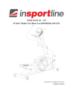
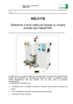
PARTS DISCRIPTION
Console
Mesh Backrest
Front Small Handlebar
Console Sleeve
Water Bottle
Pulse
Bracket
Sensor
Upright Post
Adjusting
Handle
Upright Sleeve
Seat Carriage
Assembly
Main Frame
Pull Pin
Front Stabilizer
Pedal
Rear Stabilizer
15
16
V 390 SEMI-RECUMBENT BIKE
ASSEMBLY
Step 1: Attach the Stabilizers, Leveler and Pedals
Note: the stabilizer is marked with an R to denote the right side.
Caution: Improperly rotating the pedal threads may cause damage to the equipment
A).Attach the front stabilizer to the main frame using 2x M8xp1.25x90mm Socket Head Bolts (115), 2 x M8 Lock
Washers (88) and 2 x 8x16x2.0t Washers (90). Slide the bolts through the front stabilizer and tread them in to the main
frame.
B). Attach the rear stabilizer to the main frame using 2x M8xp1.25x90mm Socket Head Bolts (115), 2 x M8 Lock
Washers (88) and 2 x 8x16x2.0t Washers (90). Slide the bolts through the rear stabilizer and tread them in to the main
frame.
C) Tilt the bike to the side and thread the leveler completely into the frame. You will adjust the leveler after assembly is
complete
D). Attach the right pedal into the right side crank. To tighten, turn the pedal treads clockwise.
E). Attach the left pedal to the left side crank. To tighten, turn the pedal threads counter clockwise
USE HARDWARE KIT
Be sure to thread the Leveler (147)
tightly into the Main Frame (1) before
moving to the next page
Tighten all bolts and fasteners now
A
www.smoothfitness.com
17
ASSEMBLY
STEP 2: Attach the Upright Post Assembly
Note: Do not tighten the upright post bolts until all four bolts are threaded into the post.
Caution: Do not pinch the wires between the frame
A). Slid the upright sleeve (34) on to the upright post assembly.
B). Attach the upright post assembly to the main frame using 4 x M8xp1.25x16mm socket head bolts (112), 4 x M8 lock
washers (88) and 4 x 8x16x2.0t washers(90).
C). Connect the Pulse Sensor Wire 3 (138) to the Pulse Sensor Wire 2 (137).
D). Connect the Rear Connection Wire (131C) to the Motor Wire (135).
E). Connect the Rear Connection Wire (131B) to the Sensor Wire (134).
F). Connect the Rear Connection Wire (131A) to the Adaptor Connection Wire (132).
G) Slide the upright post sleeve down until it attaches to the main frame covers.
USE HARDWARE KIT B
Tighten all bolts and fasteners now
18
V 390 SEMI-RECUMBENT BIKE
ASSEMBLY
STEP 3: Attach the Console and Front Handlebar
Make sure all wires are recessed into the frame. DO NOT trap or pinch the wires.
A). Attach the console bottom cover (38) to the console upper cover (37) and secure using 4 x M5xp0.8x25mm pan
head screws (97). See Fig.1
B). Remove the 4 x bolts and washers from the front handlebar.
C). Slide the front handlebar through the upright post bracket. Secure the handlebar using 5 x M8xp1.25x16mm button
head bolts (114), 5 x M8 (88) and 5 x 8x16x2.0t washers (90) Tighten all bolts now,
NOTE: One Washer (8x16x2.0t)(90), one Lock Washer (M8)(88), one Bolt, Socket Head (M8xp1.25x45mm)(114) will
be packed into the hardware bag.
Tighten all bolts and fasteners now
www.smoothfitness.com
19
ASSEMBLY
STEP 4: Attach the Console Sleeve Assembly and Water Bottle bracket
A). Slide the console sleeve assembly (39) (40) around the upright post.
B) Be certain that the sleeve assembly aligns together properly and the lowest portion of the console bottom cover is
inside the console sleeve assembly.
C). Secure the two sleeves together using 4 x M5xp0.8x15mm round head screws (99)
D). Remove the pre-installed water bottle bracket screws from the console post
E). Line up the water bottle bracket with the upright post as pictured below.
F). Secure the bracket using the previously removed 2 x M5x12mm (151) round head bolts
Tuck the lowest
portion of the console
bottom cover under
the sleeve assembly’s
lip
Tighten all bolts and fasteners now
USE HARDWARE KIT B
20
V 390 SEMI-RECUMBENT BIKE
ASSEMBLY
STEP 5: Attach the Inner Seat Carriage Slider
A). Insert the inner seat carriage slider (3) Into the main frame.
B) Slide the slider up to #5 and insert the pull pin in to the hole making sure the pan passes through the main frame
into the seat slider carriage.
C). Tighten the pull pin clockwise as much as possible.
www.smoothfitness.com
21
ASSEMBLY
STEP 7: Attach the Seat Rail and the Seat Carriage Assembly
A). Attach the fixed bracket (65) to the rear side of the seat carriage (9) and secure using 4 x M8xp1.25x16mm socket
head bolts (112), 4 x M8 (88) lock washers, and 4 x 8x16x2.0t washers (90).
B). Slide the seat carriage on to the main frame an insert the stopper bolt into hole one pictured below Fig. 3 (note the
stopper is preassembled to the bolt and nut)
C). Insert 2 x M8xp1.25x16mm socket head bolts (112), Lock Washers (M8)(88), and 2 x 8x16x2.0t washers (90)
through the left and right side of hole 2 pictured below Fig 2.
D) Secure the bottom of the front seat carriage to the main frame using 4 x M8xp1.25x16mm socket head bolts (112),
4 x M8 lock washers (88), and 4 x 8x16x2.0t washers (90) Fig. 3 & 4. Do not fully tighten until step 7 is completed.
E) Attach the rear of the seat carriage the inner seat carriage slider and secure using 1 x M10xp1.5x90mm hex head
bolt (119) and 1 x M10xp1.5 thin nylon lock nut (128) See fig. 5.
F) Tighten all bolts now
USE HARDWARE KIT C
Fig. 1
Fig. 2
Fig. 3
Fig. 4
Fig. 5
22
V 390 SEMI-RECUMBENT BIKE
ASSEMBLY
STEP 8: Attach the pulse Sensor , Rail Cover Assembly and Adjuster Handle
A). Attach the Pulse Extension wire (139) in to the connector located on the front bottom side of the seat rail (64). See
fig. 2
B). Attach the left and right covers (54) (55) over the rear of the end of the seat rail.
C). Secure the rail covers together using 2 x M5xp0.8x15mm round head screws (99)and 1 x M4x16mm self-tapping
truss head screws (93)
D). Thread 1 x M8 nut (124) on the adjuster handle stand Fig. 3.
E).Thread the adjuster handle clock wise onto the adjuster handle stand (66) to the preferred position.
F). Turn the M8 nut counter clock wise to lock the adjuster handle in place.
USE HARDWARE KIT C
Fig. 3
www.smoothfitness.com
23
ASSEMBLY
STEP 9: Attach the Seat and Handlebar Assembly
A). Attach the seat handlebar to the seat frame using 2 x M8xp1.25x50mm carriage bolts (107) and 2 x M8 nylock
nuts(127).
B). Tighten all bolts and nuts now
C). Remove the 4 preinstalled M8 nylock nuts from the seat fixed frame.
D) Attach the seat frame (11) to the seat fixed frame (10) and secure with the 4 M8 nylock nuts
E). Tighten all bolts and buts now.
F). Place the seat cushion (42) on the seat frame (11) and secure with 4 x M8xp1.25x40mm socket head bolts (113)
G). Tighten all bolts now
USE HARDWARE KIT C
24
V 390 SEMI-RECUMBENT BIKE
ASSEMBLY
STEP 10: Attach the Seat Rail and the Seat Carriage Assembly
A). Plug in the pulse sensor wire (140) into connector A located on the left side of the seat. See fig. 4.
B). Remove preinstalled 4 x 1/4’’x20mm round head screws (98) and 4 x M6 lock washers (149) from the back side of
the Mesh Backrest (41)
C). Attach the Mesh Backrest (41) to the Seat Frame (11) using 4 x (1/4’’x20mm round head screws (98) and 4 x M6
lock washers (149)
D). Tighten all bolts now
E). Insert the mesh back rest cover (148) into the recessed slot on the back of the seat frame(11). See fig. 5
ASSEMBLY IS NOW COMPLETE. RECHECH THAT BOLTS ARE TIGHT.
Fig. 5
www.smoothfitness.com
25
GENERAL INFORMATION
THE POWER SUPPLY
The power input is located at the lower front of the bike
HOW TO ADJUST THE REAR STABILIZER
a. After placing the equipment in the intended location for use, it may be necessary to level the equipment.
b. To level the equipment turn the dial in the center of the rear stabilizers
HOW TO ADJUST MAIN FRAME’S LEVELER
a. After adjusting the rear end cap stabilizers you may need to adjust
the main frame stabilizer. Turn the stabilizer A clockwise or
counterclockwise to raise or lower. Turn the locking nut clockwise to
lock the stabilizer in place
26
V 390 SEMI-RECUMBENT BIKE
GENERAL INFORMATION
HOW TO ADJUST CONSOLE ANGLE
To get the best console angle, it’s suggested to use both hands to hold the upper and
lower end of the console and gently adjust the console angle to the proper position
HOW TO MOVE THE ITEM SAFELY
Hold the Rear Stabilizer (6) up with two hands and tow the item to the
desired place carefully
Make sure the floor is level while towing the item
www.smoothfitness.com
27
GENERAL INFORMATION
HOW TO ADJUST THE SEAT
a. To adjust the seat distance from the pedals, it’s
suggested to place your feet on each pedal.
b. Use your right hand to lift up the Adjusting Handle
(A) while using your feet to slide the seat distance
forward or backward until the seat reaches to the
proper position.
c. Release and secure the Adjusting Handle (A). After
releasing the Adjusting Handle (A), push the seat
forward of back until you hear a “click” sound.
28
V 390 SEMI-RECUMBENT BIKE
GENERAL INFORMATION
THE SEAT ANGLE ADJUSTMENT
a. Adjust The Seal Angle:
1. Determine the seat angle that you prefer. On the Inner Seat Carriage Slider (3) there is a numbered scale from
1 to 5; from 9 to 45 degree (9 degree increment)
2. Loosen the Pull Pin (29) by turning it counter-clockwise
3. Use your one hand to pull the Pull
Pin (29) outward while use the
other hand to put your fingers into
the hand grip, located on the back
of the Rail Cover (54,55), to slide
the Inner Seat Carriage Slider (3)
upward or downward to the proper
seat angle. Release the pin when
the preferred angle is achieved.
4. Make sure the pin on the Pull Pin (29) locks into position then turn
the clockwise to tighten.
b. HORIZONTAL ADJUSTMENT OF THE SEAT:
1. After adjusting the seat angle, you
will need to adjust the seat pad
horizontally.
2. Behind the Seat Carriage Cover
(48, 49), there is a number scale
from 1 to 5. The number is designed to match the number of the Inner Seat
Carriage Slider (3)
3. To adjust the seat horizontally, pull the Locking Pin (47) outward and adjust the
Seat Cushion (42) upward or downward until the seat is horizontal. Release the Locking Pin (47) to lock the seat.
When the pin click in position the seat is locked.
www.smoothfitness.com
29
IMPORTANT STEPS
Warning:
Before using this product, please consult your personal physician for a complete physical examination. Frequent and
strenuous exercise should be approved by your doctor first. If any discomfort should result from your use of this
product, stop exercising and consult your doctor. Proper usage of this product is essential. Please read your manual
carefully before exercising.
Avertissement :
Avant d’utiliser de produit, veuillez consulter votre médecin personnel pour un examen médical complet. Des
exercices fréquents et difficiles doivent d’abord être approuvés par votre médecin. Si vous ressentez un malaise par
suite de l’utilisation de produit, arrêtez les exercices et consultez votre médecin. Un usage approprié de ce produit est
essentiel. Veuillez lire attentivement votre manuel avant de commencer les exercices.
Les enfants doivent rester éloignés de l’équipement pendant son utilisation et lorsqu’il est laissé sans surveillance.
Portez toujours des vêtements appropriés pour les exercices, y compris des chaussures d’athlétisme. Ne portez pas
de vêtements amples qui pourraient être pris dans l’appareil durant les exercices.
Please keep all children away from the equipment during use and when equipment is unattended.
Always wear appropriate clothing, including athletic shoes, when exercising. Do not wear loose clothing that could
become caught during exercising.
Make sure that all bolts and nuts are tightened when equipment is in use. Periodic maintenance is required on all
exercise equipment to keep it in good condition.
Before beginning:
How you begin your exercise program depends on your physical condition. If you have been inactive for several
years, or are severely overweight, you must start slowly and increase your time gradually, a few minutes per week.
Initially you may be able to exercise only for a few minutes in your target zone. However, your aerobic fitness will
improve over the next six to eight weeks. Don’t be discouraged if it takes longer. It’s important to work at your own
pace. Ultimately, you’ll be able to exercise continuously for 30 minutes. And the better your aerobic fitness, the
harder you will have to work to stay in your target zone. But remember these essentials:
•
Contact your physician before starting a workout or training program. Have your doctor review your training
and diet programs to advise you of a workout routine you should adopt.
•
Begin your training program slowly with realistic goals that have been set by you and your doctor.
•
Supplement your program with some type of aerobic exercise such as walking, jogging, swimming, dancing
and/or bicycling. Monitor your pulse frequently. If you do not have an electronic heart rate monitor, have your
physician show you the proper way to manually check your pulse by using your wrist or neck. Establish your
target heart rate based on your age and condition.
•
Drink plenty of fluids during the course of your routine. You must replace the water content lost from
excessive exercising to avoid dehydration. Avoid drinking large amounts of cold liquids. Fluids should be at
room temperature when consumed.
30
V 390 SEMI-RECUMBENT BIKE
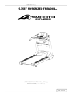
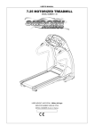
MUSCLE CHART
Targeted muscle groups:
The exercise routine that is performed on this product will develop primarily lower body muscle groups. These muscle
groups are shown in gray color on the chart below.
MUSCLE GROUPS
A
Shoulder muscles
B
Pectoral muscles
C
Bicep muscle
D
Abdominal muscles
E
Forearm muscles
F
Quadricep muscles
Calf muscles
G
Trapezius muscles
H
Tricep muscles
I
Back muscles
J
Gluteal muscles
K
Hamstring muscles
L
www.smoothfitness.com
31
STRETCHING ROUTINE
Warm up and cool down:
A successful exercise program consists of a warm-up, aerobic exercise, and a cool-down. Do the entire program at least two and
preferably three times a week, resting for a day between workouts. After several months, you can increase your workouts to four or
five times per week.
Warming up is an important part of your workout, and should begin every session. It prepares your body for more strenuous
exercise by heating up and stretching out your muscles, increasing your circulation and pulse rate, and delivering more oxygen to
your muscles. At the end of your workout, repeat these exercises to reduce sore muscle problems. We suggest the warm-up and
cool-down exercises on the following pages:
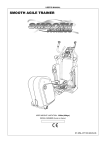
Toe Touch:
Slowly bend forward from
your waist, letting your back
and shoulders relax as you
stretch toward your toes.
Reach down as far as you
can and hold for 15 counts.
Shoulder Lift:
Lift your right shoulder up
toward your ear for one
count. Then lift your left
shoulder up for one count as
you lower your right
shoulder.
Inner Thigh Stretch:
Sit with the soles of your feet
together with your knees
pointing outward. Pull your
feet as close into your groin
as possible. Gently push
your knees towards the floor.
Hold for 15 counts.
Hamstring Stretch:
Sit with your right leg
extended. Rest the sole of
your left foot against your
right inner thigh. Stretch
toward your toe as far as
possible. Hold for 15 counts.
Relax and then repeat with
left leg extended.
Side Stretch:
Open your arms to the side
and continue lifting them until
they are over your head.
Reach your right arm as far
upward toward the ceiling as
you can for one count. Feel
the stretch up your right side.
Repeat this action with your
left arm.
Calf-Achilles Stretch:
Lean against a wall with your
left leg in front of the right
and your arms forward. Keep
your right leg straight and the
left foot on the floor; then
bend the left leg and lean
forward by moving your hips
toward the wall. Hold, and
then repeat on the other side
for 15 counts.
Head Roll:
Rotate your head to the right
for one count, feeling the
stretch up the left side of your
neck. Next, rotate your head
back for one count, stretching
your chin to the ceiling and
letting your mouth open.
Rotate your head to the left
for one count, and finally,
drop your head to your chest
for one count.
32
V 390 SEMI-RECUMBENT BIKE
STRETCHING ROUTINE
Read carefully the following before using your bike
♦
♦
♦
♦
Always stretch your muscles before exercise program. Warm up slowly by walking at a slow speed. Increase workout
intensity gradually until you reach your desired workout pace. Decrease workout intensity gradually to an easy walk,
allowing your heart rate to decrease to a normal situation.
When starting the bike, always stand with both feet on the step-on side rails.
When finishing, allow the running belt to slow down and come to a complete stop before stepping off.
Wear comfortable, non-restrictive clothing when using the bike. Never wear anything loose, such as baggy sweat pants,
neckties, loose socks or jewelry. Never drape towels on or around the bike during use.
WARNING
If you feel dizzy, nausea, chest pain or other abnormal symptoms, stop immediately. Consult a physician before continuing
use.
AVERTISSEMENT: Si vous vous sentez étourdi, la nausée, la douleur de coffre ou d'autres symptômes anormaux,
s'arrêtent immédiatement. Consultez un médecin avant de continuer l'utilisation.
♦
♦
♦
Always use the handrail when stepping on or off the bike and when changing incline or speed.
This bike is equipped with a safety key – always clip the cord attached to the safety key to a part of your clothing so the
safety key will properly detach from the computer console, thereby stopping the bike.
Wear running or walking shoes with high-traction soles. To avoid injury and unnecessary wear on your bike, be sure
your shoes are free of any debris such as gravel and small rocks.
Before completing an exercise session, always:
1. Allow time to slow your pace, cool down, and reduce your heart rate to a normal level before completing your workout.
2. Grasp the handlebars and press the Speed “?” button. Slow your pace to an easy walk.
3. Ensure the running belt has come to a complete stop before exiting the bike.
WARNING
Turn off and unplug the bike before proceeding with any maintenance or visual inspections. Failure to do so may result in
serious injury. Note: Failure to perform the required periodic and preventative maintenance can void your warranty.
AVERTISSEMENT
Arrêtez et débranchez le tapis roulant avant de procéder à tout l'entretien ou inspections visuelles. Le manque de faire ainsi
peut avoir comme conséquence des dommages sérieux. Note : Le manque d'exécuter l'entretien périodique et préventif
exigé peut vider votre garantie.
At the end of every exercise session, always:
1. Remove the Safety Key from the computer console.
2. Use the master power switch to turn the bike off. The master power switch is located at the right side of frame next to the
electrical cord.
3. Always position and store the electrical cord where is clear from all pathways.
4. Unplug the electrical cord from the electrical outlet. This is especially important if you are not going to use your bike for
extended periods.
5. Wipe all bike surfaces with a dry cloth or towel especially perspiration on the handlebars, con troll panel, running belt or
other bike components.
www.smoothfitness.com
33
COMPUTER OPERATION
Congratulations this product is equipped with the MY SMOOTH Virtual Fitness Trainer. Whether you
want to lose weight, train for a sporting event, or simply maintain a healthy lifestyle, the MY SMOOTH
Virtual Fitness Trainer provides the tools, structure and support you need to be fit and live healthy. The 5
simple steps, outlined in the customer care kit* are proven to help you lose weight, improve your health,
and make positive steps to a healthier lifestyle. These five steps combined with the tools built into your
online account, will provide you with a great start toward achieving your goals.
To set up your account, refer to the instructions in the Getting Started Guide contained in your Smooth
Fitness customer care kit or visit www.my smoothtrainer.com
*Not all Smooth Fitness products include the Smooth Customer Care Kit
34
V 390 SEMI-RECUMBENT BIKE
COMPUTER OPERATION
Take a few minutes
to review the console
layout. Below is an
overview of the
console’s features
and functions
We recommend that
you use the console
to help vary your
workout routine and
keep you focused on
your process toward
your fitness goals.
The console can
become an important
source of motivation
and interest which
will help keep you on
track
Power ON
a. Make sure the item’s adaptor is correctly plugged into the socket
b. Pedaling or pressing any keys to active the console. The console display will then light up with a short beep sound,
indicating the console will be ready for use
Power Off
The console would automatically shut off after 5 minutes of inactivity
Program List
MANUAL
P1 WEIGHT LOSS
P2 NOV. INTERVAL
P3 INT. INTERVAL
P4 MOUNTAIN CLIMB
P5 HILL CLIMB
P6 ROLLING HILLS
P7 GRAD. INTERVAL
P8 PLATEAU
P9 ADV. INTERVAL
P10 LADDER
P11 USER 1
P12 USER 2
P13 H.R.C.
P14 H.R.C. INTERVAL
www.smoothfitness.com
35
COMPUTER OPERATION
Console Buttons
a.
b.
c.
d.
Press START/PAUSE to begin your exercise
Press START/PAUSE again to stop and pause all functions during your exercise program. All the data on
the display will then pause.
Press START/PAUSE again to resume the program and all the data displayed will continue until the
program has finished.
HOLD TO RESET function: Press and hold START/PAUSE, all the data will return to 0 and the console
will return to POWER ON status.
Press ENTER to confirm the program function (PROGRAM, TIME, HEIGHT, WEIGHT, AGE, TARGET H.R.
and LEVEL in each time interval).
Press UP to increase the values of the program function (PROGRAM, TIME, HEIGHT, WEIGHT, AGE,
TARGET H.R. and LEVEL in each time interval).
Press DOWN to decrease the values of the program function (PROGRAM, TIME, HEIGHT, WEIGHT, AGE,
TARGET H.R. and LEVEL in each time interval).
**The button is only suitable to
use when the USB is plugged
a.
b.
c.
d.
into the console**
Press MODE to
review Calendar Mode.
Hold MODE for a few seconds, to go into Calendar Mode to edit
year/month/date/hour/minute.
Calendar Mode
Press Start/ Pause /Hold to reset to return to POWER ON
status.
PULSE RECOVERY button measures how quickly you return to a
resting heart rate after exercising. You could use this button to
measure improvement as you get into shape.
The console will monitor your pulse for 60 seconds and calculate a
HEART RATE RECOVERY value from F1.0 to F6.0. F1.0 is the
Highest; F6.0 is the Lowest (For Reference Only).
The readout should only be used as a comparison between workouts. It’s recommended to use right after
any aerobic exercise. Stop exercising before starting this function.
Your pulse will be displayed in approximately 5 seconds after the heart symbol “ ” is displayed.
NOTE:
If you don’t hold the HEART RATE SENSORS on the handrails with
both hands properly, the console’s HEART RATE value will show “0”
and the main screen would show “F6.0” after the console counts down
to zero, If the sensor was unable to read your heart rate. Press stop
then press the PULSE RECOVERY button again. Replace your hands
on the pulse sensors.
36
V 390 SEMI-RECUMBENT BIKE
COMPUTER OPERATION
Console Buttons
Speaker Sound System:
To enjoy your workout with music, simply connect any MP3/CD player to the LINE IN
jack on the console.
The console is allowed you to use Headphone or Speakers when listening to the music.
Turn the Volume Knob (located on the left side of the console) to adjust the proper sound
level.
To record your exercise and health metrics, you must log on
to www.mysmoothtrainer.com . Then sync your MY Smooth Virtual Fitness Trainer USB
device. Once complete simply plug in the MY Smooth Virtual Fitness Trainer USB device
to you compatible Smooth Fitness exercise machine. Displayed on the equipment will be
your name, weight height and age. Press “START” button to begin your workout, the
console will record your exercise data automatically, every 20 seconds, to your MY
Smooth Virtual Fitness Trainer USB device. After your exercise session is complete,
insert the MY Smooth
device in to the USB port
of your PC or MAC to
upload your data to The
MY Smooth Virtual Fitness
Trainer online health
management program.
The detailed reports show
your exercise and health
results, trends and recommendations to better achieve and maintain your fitness goals.
www.smoothfitness.com
COMPUTER OPERATION
Console Functions
CALORIES:
Count Up: Measuring total calories your body burned
during exercise.
Display range: 0 ~ 9999.
SPEED:
Displays the current speed KM/MILE during exercise.
RPM (Rotation Per Minute):
Display range: 0 ~ 999.
TIME:
Count Up: If a target time was not selected, TIME will count
up from 0:00 to maximum 99:59 minutes.
Count Down: If you have set the target time (0:00 ~ 99:00),
the console will count down from that selected target time
down to 0:00.
WATTS:
Displays the current value of Watt during exercise.
Display range: 0 ~ 9999.
DISTANCE:
Count Up: If a target distance was not selected, this would
measure the total distance from 0:00 to 999.9 km/mile.
Count Down: If you have set the target distance, the
console will count down from that selected target distance
down to 0.
: Display POWER SUPPLY status.
HAND PULSE / HEART RATE:
To display your heart rete you must wear the chest belt or
place both of your hands on the Pulse Sensors located on
the Handlebars. Your pulse will be displayed
approximately 5 seconds after the heart symbol “
” is
displayed.
If you do not wear the chest belt or place your hands
correctly on the pulse sensors, the computer will shut off
the pulse circuit. To reactivate the pulse feature, properly
place your hands back on the Pulse Sensors and the pulse
readout will appear again.
: When the MY SMOOTH USB is plugged into the
console, the USB signal will be displayed on the
console.
37
38
V 390 SEMI-RECUMBENT BIKE
COMPUTER OPERATION
GENDER:
Display range:
Male:
Female:
AGE:
Display range:
10 ~ 99 years old; in 1 year increments
NOTE: Although the console allows input for age
beginning at 10 years old, the product is not
recommended for use by children.
HEIGHT:
Display range:
3 FEET 4 INCHES ~ 7 FEET; 1 INCH increments / 101 ~ 214
CM; 1 CM increments; the product is not recommended for
use by children.
WEIGHT:
Display range:
45 ~ 400LBS; 1 LB increments / 20 ~ 181 KGS; 1 KG
increments; the product is not recommended for use by
children.
TARGET H.R.:
Display range:
50 ~ 180 BPM (beats per minute) ; 1 BPM increments.
www.smoothfitness.com
39
COMPUTER OPERATION
“1” Press any button on the console to turn on the console
a. Make sure that the power cord is properly plugged into the socket.
b. The console would automatically shut off after 5 minutes of inactivity.
c.
Press any button on the console or begin pedaling to turn on the console. After a few seconds, the console will then
light up with a short beep sound, indicating the console will be ready for use.
“2””Start Pause” button, as an easy way to reset the computer and enter into POWER ON status
Hold the START/PAUSE button for a few seconds to reset the computer and
returning all workout values to zero, and enter into POWER ON status.
POWER ON status
3” MANUAL PROGRAM
“A.“ENTER MANUAL PROGRAM”
QUICK START:
Pressing When in Power on status
press the start button to immediately
start a manual program
ENTER the USER DATA
or
Press the UP or Down Button until MANUAL
is displayed. Press Enter to confirm. Once the
MANUAL program has been chosen you will
enter your personal information by following
the directions on the next page.
40
V 390 SEMI-RECUMBENT BIKE
COMPUTER OPERATION
“B. SET YOUR GENDER“
a. After pressing UP or Down button to enter into MANUAL
function mode will appear with
PROGRAM press ENTER to Confirm, the GENDER
/Male icon display flashing.
b. Use UP or DOWN buttons to set your gender (Male:
or Female:
).
c. Press the ENTER button to confirm.
“C. SET YOUR AGE“
a. The AGE function will appear with the AGE display flashing.
b. Use the UP or DOWN buttons to set your AGE (10 ~ 99 YEARS OLD; in 1 YEAR
INCREMENTS).
c.
Press the ENTER button to confirm .NOTE: Although the console allows input for age
beginning at 10 years old, the product is not recommended for use by children
“D. SET YOUR HEIGHT“
a. The HEIGHT function will appear with the HEIGHT display flashing.
b. Use the UP or DOWN buttons to set your HEIGHT (3 FEET 4 INCHES ~ 7
FEET; 1 INCH INCREMENTS/ 101 ~ 214 CM; 1 CM INCREMENTS).
c.
Press the ENTER button to confirm.
NOTE for HEIGHT: The product is not recommended for use by children
“E. SET YOUR WEIGHT“
a. The WEIGHT function will appear with the WEIGHT display flashing.
b. Use the UP or DOWN buttons to set your WEIGHT (45 TO 400 LBS / 20 TO 181KGS; 1
LBS/KG INCREMENTS).
c.
Press the ENTER button to confirm.
NOTE for WEIGHT: The product is not recommended for use by children
www.smoothfitness.com
41
COMPUTER OPERATION
“F. SET THE TIME“
a. The TIME function will appear with the TIME display flashing.
b. Use the UP or DOWN buttons to set the desired TIME (00:00 TO 99:00; 1 MINUTE
INCREMENTS).
c.
Press the ENTER button to confirm.
NOTE for TIME:
Count Up: If a target time was not selected, the TIME will count up from 0:00 to a maximum of 99:59 minutes
Count Down: If you have set the target time, the console will count down from that selected target time to
0:00
“G. START TO EXERCISE”
Press START/ PAUSE to begin your exercise.
“H. CHANGING THE RESISTANCE SETTING”
You can change the resistance level (from 1 to 16 levels) at any time during
workout by pressing the UP or DOWN button
42
V 390 SEMI-RECUMBENT BIKE
COMPUTER OPERATION
“CONSOLE INSTRUCTIONS – PROGRAM (P2 ~ P10)”
“A.“ENTER THE PRESET PROGRAMS”
To enter one of the nine preset programs.
a. Press any button on the console to turn on the console. After a few seconds, the console will then light up with
b.
c.
d.
e.
f.
a short beep sound, indicating the console will be ready for use.
Make sure that the power cord is properly plugged into the socket.
The console would automatically shut off after 5 minutes of inactivity.
Press the UP or DOWN buttons to select program 2 ~ 10 (SEE PROGRAM SELECTION ON PAGE 45)
Once the preferred program is displayed press enter to confirm.
Enter your USER Data
“B. SET YOUR GENDER”
a. After pressing UP or Down button to enter into MANUAL
function mode will appear with
PROGRAM press ENTER to Confirm, the GENDER
/Male icon display flashing.
b. Use UP or DOWN buttons to set your gender (Male:
c. Press the ENTER button to confirm.
or Female:
).
“C. SET YOUR AGE”
a. The AGE function will appear with the AGE display flashing.
b. Use the UP or DOWN buttons to set your AGE (10 ~ 99 YEARS OLD; in 1 YEAR INCREMENTS).
c. Press the ENTER button to confirm .NOTE: Although the console allows input for age beginning at 10 years old, the
product is not recommended for use by children.
www.smoothfitness.com
43
COMPUTER OPERATION
“D. SET YOUR HEIGHT”
a. The HEIGHT function will appear with the HEIGHT display flashing.
b. Use the UP or DOWN buttons to set your HEIGHT (3 FEET 4 INCHES ~ 7
FEET; 1 INCH INCREMENTS/ 101 ~ 214 CM; 1 CM INCREMENTS).
c.
Press the ENTER button to confirm.
NOTE for HEIGHT: The product is not recommended for use by children
“E. SET YOUR WEIGHT”
a. The WEIGHT function will appear with the WEIGHT display flashing.
b. Use the UP or DOWN buttons to set your WEIGHT (45 TO 400 LBS / 20 TO 181KGS; 1
LBS/KG INCREMENTS).
c.
Press the ENTER button to confirm.
NOTE for WEIGHT: The product is not recommended for use by children
“F. SET THE TIME”
a. The TIME function will appear with the TIME display flashing.
b. Use the UP or DOWN buttons to set the desired TIME (00:00 TO 99:00; 1 MINUTE
INCREMENTS).
c.
Press the ENTER button to confirm.
NOTE for TIME:
Count Up: If a target time was not selected, the TIME will count up from 0:00 to a maximum of 99:59 minutes
Count Down: If you have set the target time, the console will count down from that selected target time to
0:00
44
V 390 SEMI-RECUMBENT BIKE
COMPUTER OPERATION
“G. START TO EXERCISE”
Press START/ PAUSE to begin your exercise.
“H. CHANGING THE RESISTANCE SETTING”
You can change the resistance level (from 1 to 16 levels) at any time during workout by pressing the UP or DOWN button
www.smoothfitness.com
COMPUTER OPERATION
P1 WEIGHT LOSS
P3 INTERMEDIATE INTERVAL
P5 HILL CLIMB
P2 NOVICE INTERVAL
P4 MOUNTAIN CLIMB
P6 ROLLING HILLS
P7 GRADUATING INTERVAL
P8 PLATEAU
P9 ADVANCED INTERVAL
P10 LADDER
45
46
V 390 SEMI-RECUMBENT BIKE
COMPUTER OPERATION
“CONSOLE INSTRUCTIONS – PROGRAM (P11 ~ 12)”
P11 USER 1
P12 USER 2
“1” To enter one of the 2 USER programs.
a. Press any button on the console to turn on the console. After a few seconds, the console will then light up with
b.
c.
d.
e.
f.
a short beep sound, indicating the console will be ready for use.
Make sure that the power cord is properly plugged into the socket.
The console would automatically shut off after 5 minutes of inactivity.
Press the UP or DOWN buttons to select program 11~12
Once the preferred program is displayed press enter to confirm.
Enter your USER Data
“B. SET YOUR GENDER”
a. After pressing UP or Down button to enter into MANUAL
function mode will appear with
PROGRAM press ENTER to Confirm, the GENDER
/Male icon display flashing.
b. Use UP or DOWN buttons to set your gender (Male:
c. Press the ENTER button to confirm.
or Female:
).
www.smoothfitness.com
47
COMPUTER OPERATION
”C. SET YOUR AGE”
a. The AGE function will appear with the AGE display flashing.
b. Use the UP or DOWN buttons to set your AGE (10 ~ 99 YEARS OLD; in 1 YEAR INCREMENTS).
c. Press the ENTER button to confirm .NOTE: Although the console allows input for age beginning at 10 years old,
the product is not recommended for use by children
“D. SET YOUR HEIGHT”
a. The HEIGHT function will appear with the HEIGHT display flashing.
b. Use the UP or DOWN buttons to set your HEIGHT (3 FEET 4 INCHES ~ 7
FEET; 1 INCH INCREMENTS/ 101 ~ 214 CM; 1 CM INCREMENTS).
c.
Press the ENTER button to confirm.
NOTE for HEIGHT: The product is not recommended for use by children
“E. SET YOUR WEIGHT”
a. The WEIGHT function will appear with the WEIGHT display flashing.
b. Use the UP or DOWN buttons to set your WEIGHT (45 TO 400 LBS / 20 TO 181KGS; 1
LBS/KG INCREMENTS).
c.
Press the ENTER button to confirm.
NOTE for WEIGHT: The product is not recommended for use by children
48
V 390 SEMI-RECUMBENT BIKE
COMPUTER OPERATION
“F. SET THE TIME”
a. The TIME function will appear with the TIME display flashing.
b. Use the UP or DOWN buttons to set the desired TIME (00:00 TO 99:00; 1 MINUTE
INCREMENTS).
c.
Press the ENTER button to confirm.
NOTE for TIME:
Count Up: If a target time was not selected, the TIME will count up from 0:00 to a maximum of 99:59 minutes
Count Down: If you have set the target time, the console will count down from that selected target time to
0:00
G. START TO EXERCISE”
Press START/ PAUSE to begin your exercise.
“H. CHANGING THE RESISTANCE SETTING”
You can change the resistance level (from 1 to 16 levels) at any time during workout by pressing the UP or DOWN button
“2” Programming the 2 USER programs.
a.
b.
c.
d.
e.
Once the USER data has been entered press the UP or DOWN buttons to adjust the level of the first segment.
Press enter to confirm and move to the next segment
Repeat this process until the preferred program has been completed.
Press start to save and begin the program
This program can be overwritten at any time in the set up screen.
www.smoothfitness.com
49
COMPUTER OPERATION
“1” Prior information: Press any button on the console to turn on the console
a.
b.
c.
Make sure that the power cord is properly plugged into the socket.
The console would automatically shut off after 5 minutes of inactivity.
Press any button on the console to turn on the console. After a few seconds, the console will then light up with a
short beep sound, indicating the console will be ready for use.
“2” Prior information: ”HOLD TO RESET” button, an easy way to reset and enter into POWER
ON status
Continue pressing START/PAUSE
button a few seconds, all the date will
reset to the initial value and the console
will return to POWER ON status.
POWER ON status
“3” PROGRAM (P13)
“A. ENTER P13“
UP or DOWN button and then ENTER button:
Press UP or DOWN button to select PROGRAM
(P13) and then press ENTER button to confirm and enter
PROGRAM (P13).
“B. SET YOUR GENDER“
UP or DOWN button & then ENTER button:
a. After pressing the ENTER button to enter into H.R.C.
appear with
/Male icon display flashing.
b. Use UP or DOWN buttons to set your gender (Male:
c.
PROGRAM (P13), the GENDER function mode will
or Female:
).
Press the ENTER button to confirm your GENDER and enter the mode to set the AGE.
50
V 390 SEMI-RECUMBENT BIKE
COMPUTER OPERATION
“CONSOLE INSTRUCTIONS –H.R.C. PROGRAM (P13)”
“C. SET YOUR AGE“
UP or DOWN button & then ENTER button:
a. The AGE function mode will appear with the value of AGE display flashing.
b. Use UP or DOWN buttons to set your personal AGE (10 ~ 99 YEARS OLD; 1
YEAR-OLD INCREMENT).
c.
Press the ENTER button to confirm AGE value and enter the HEIGHT
mode. NOTE: Although the console allows input for age beginning at 10 years
old, the product is not recommended for children’s use
“D. SET YOUR PERSONAL HEIGHT“
UP or DOWN button & then ENTER button:
a. The HEIGHT function mode will appear with the value of HEIGHT
display flashing.
b. Use UP or DOWN buttons to set your personal HEIGHT (3 FEET 4
INCHES ~ 7 FEET; 1 INCH increment / 101 ~ 214 CM; 1 CM
INCREMENT).
c.
Press the ENTER button to confirm HEIGHT value and enter the WEIGHT mode.
NOTE for HEIGHT: The product is not recommended for children’s use
“E. SET YOUR PERSONAL WEIGHT“
UP or DOWN button & then ENTER button:
a. The WEIGHT function mode will appear with the value of WEIGHT display flashing.
b. Use UP or DOWN buttons to set your personal WEIGHT (45 TO 400 LBS / 20 TO
181KGS; 1 LBS/KG INCREMENT).
c.
Press the ENTER button to confirm WEIGHT value and enter the TIME mode.
NOTE for WEIGHT: The product is not recommended for children’s use
“F. SET THE DESIRED TIME“
UP or DOWN button & then ENTER button:
a. The TIME function mode will appear with the value of TIME display flashing.
b. Use UP or DOWN buttons to set the desired TIME (00:00 TO 99:00; 1 MINUTE
INCREMENT).
c.
Press the ENTER button to confirm TIME value and enter the TARGET HEART RATE
mode.
www.smoothfitness.com
51
COMPUTER OPERATION
“CONSOLE INSTRUCTIONS –H.R.C. PROGRAM (P13)”
“G. SET THE TARGET HEART RATE“
UP or DOWN button & then ENTER button:
a. The TARGET HEART RATE function mode will appear with the value of TARGET HEART
RATE display flashing.
b. Use UP or DOWN button to set your desired TARGET HEART RATE (50 ~ 180 BPM
(BEATS PER MINUTE; 1 BPM INCREMENT).
c. Press the ENTER button to confirm TARGET HEART RATE value.
“H. START EXERCISE”
START/ PAUSE button: Press START/ PAUSE to begin exercise.
I. MUST-KNOWN HEART RATE PROGRAM INFO.”
CONSOLE MONITOR YOUR CURRENT PULSE TO COMPARE WITH YOUR
SETTING TARGET HEART RATE:
3 minute WARM UP time: After enter the H.R.C. program, the program will start
begin with 3 minute WARM UP time, during the WARM UP mode, the console
will detects the user’s heart rate through hand pulse sensors or wireless chest
belt. During the WARM UP time, the torque/resistance level is available to adjust
from 1 ~ 16 levels.
After the 3-minute warm up is complete, then go into the H.R.C. main program (the time will change to your desired stepup time, the resistance will return to the Level 1). The console at this time will monitor your actual pulse and adjust the
resistance/torque level automatically to keep your pulse within your TARGET HEART RATE ZONE.
If you current pulse > (the value of the TARGET HEART RATE + 10), the console would decrease one
resistance/torque level automatically.
If you current pulse < (the value of the TARGET HEART RATE - 10), the console would increase one resistance/torque
level automatically.
NOTE: During H.R.C. main program, if you do not wear a
chest belt or place your hands correctly on the pulse
sensors, after 30 seconds, the console will display “NO
HEART RATE” message and then turn off the pulse circuit
and stop the program. The console will then display an
error message “PAUSE”. Press START button and be sure
to wear a chest belt or place your hands back on the Pulse
Sensors correctly, the pulse readout will appear again and
continue starting the program.
52
V 390 SEMI-RECUMBENT BIKE
COMPUTER OPERATION
“CONSOLE INSTRUCTIONS –H.R.C. INTERVAL PROGRAM (P14)”
“1” Prior information: Press any button on the console or begin pedaling to turn on the console
a.
b.
c.
Make sure that the power cord is properly plugged into the socket.
The console would automatically shut off after 5 minutes of inactivity.
Press any button on the console or begin pedaling to turn on the console. After a few seconds, the console will then
light up with a short beep sound, indicating the console will be ready for use.
“2” Prior information: ”HOLD TO RESET” button, an easy way to reset and enter into POWER ON
status
Continue pressing HOLD TO RESET
button a few seconds, all the date will
reset to the initial value and the console
will return to POWER ON status.
“3” Normal way to operate PROGRAM (P14)
POWER ON status
“A. ENTER P14“
UP or DOWN button and then ENTER button:
Press UP or DOWN button to select H.R.C.
confirm and enter PROGRAM
INTERVAL PROGRAM (P14) and then press ENTER button to
(P14).
“B. SET YOUR GENDER“
UP or DOWN button & then ENTER button:
a. After pressing the ENTER button to enter into H.R.C.
will appear with
/Male icon display flashing.
b. Use UP or DOWN buttons to set your gender (Male:
c.
INTERVAL PROGRAM (P14), the GENDER function mode
or Female:
).
Press the ENTER button to confirm your GENDER and enter the mode to set the AGE.
www.smoothfitness.com
53
COMPUTER OPERATION
“CONSOLE INSTRUCTIONS –H.R.C. INTERVAL PROGRAM (P14)”
“C. SET YOUR AGE“
UP or DOWN button & then ENTER button:
a. The AGE function mode will appear with the value of AGE display flashing.
b. Use UP or DOWN buttons to set your personal AGE (10 ~ 99 YEARS OLD; 1
YEAR-OLD INCREMENT).
c.
Press the ENTER button to confirm AGE value and enter the HEIGHT
mode. NOTE: Although the console allows input for age beginning at 10 years
old, the product is not recommended for children’s use
“D. SET YOUR PERSONAL HEIGHT“
UP or DOWN button & then ENTER button:
a. The HEIGHT function mode will appear with the value of HEIGHT
display flashing.
b. Use UP or DOWN buttons to set your personal HEIGHT (3 FEET 4
INCHES ~ 7 FEET; 1 INCH increment / 101 ~ 214 CM; 1 CM
INCREMENT).
c.
Press the ENTER button to confirm HEIGHT value and enter the WEIGHT mode.
NOTE for HEIGHT: The product is not recommended for children’s use
“E. SET YOUR PERSONAL WEIGHT“
UP or DOWN button & then ENTER button:
a. The WEIGHT function mode will appear with the value of WEIGHT display flashing.
b. Use UP or DOWN buttons to set your personal WEIGHT (45 TO 400 LBS / 20 TO
181KGS; 1 LBS/KG INCREMENT).
c.
Press the ENTER button to confirm WEIGHT value and enter the TIME mode.
NOTE for WEIGHT: The product is not recommended for children’s use
“F. SET THE DESIRED TIME“
UP or DOWN button & then ENTER button:
a. The TIME function mode will appear with the value of TIME display flashing.
b. Use UP or DOWN buttons to set the desired TIME (00:00 TO 99:00; 1 MINUTE
INCREMENT).
c.
Press the ENTER button to confirm TIME value and enter the HIGH TARGET HEART
RATE mode.
54
V 390 SEMI-RECUMBENT BIKE
COMPUTER OPERATION
“CONSOLE INSTRUCTIONS –H.R.C. INTERVAL PROGRAM (P14)”
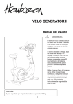
“G. SET THE HIGH TARGET HEART RATE“
UP or DOWN button & then ENTER button:
Age
Average Max./High
Heart Rate 75%
a. The HIGH TARGET HEART RATE function
20
25
30
35
40
45
50
55
60
65
70
150 beats per minute
146 beats per minute
142 beats per minute
138 beats per minute
135 beats per minute
131 beats per minute
127 beats per minute
124 beats per minute
120 beats per minute
116 beats per minute
112 beats per minute
mode will appear with the value of HIGH
TARGET HEART RATE display flashing.
NOTE: the default value of HIGH TARGET
HEART RATE is based on 75% of (220 –
your age).
b. However, if the default value of HIGH TARGET HEART RATE doesn’t
match your need, it’s able to use UP or DOWN button to slightly adjust
your desired HIGH TARGET HEART RATE (70 ~ 180 BPM (BEATS PER
MINUTE; 1 BPM INCREMENT). NOTE: HIGH TARGET HEART RATE
Reference Table
must higher 10 + value of LOW TARGET HEART RATE in order to make this program workable. Make sure that
the setting value of HIGH TARGET HEART RATE is reachable to your ideal health condition as the console will
monitor your actual heart rate comparing with HIGH TARGET HEART
RATE to automatically adjust the resistance level.
Age
Target Heart Rate
Zone
(60% of Min./Low Heart
Rate)
20
25
30
35
40
45
50
55
60
65
70
120 beats per minute
117 beats per minute
114 beats per minute
111 beats per minute
108 beats per minute
105 beats per minute
102 beats per minute
99 beats per minute
96 beats per minute
93 beats per minute
90 beats per minute
c. Press the ENTER button to confirm HIGH TARGET HEART RATE value and
enter the LOW TARGET HEART RATE mode.
“H. SET THE LOW TARGET HEART RATE“
UP or DOWN button & then ENTER button:
a. The LOW TARGET HEART RATE function mode
will appear with the value of LOW TARGET
HEART RATE display flashing. NOTE: the
default value of LOW TARGET HEART RATE is
based on 60% of (220 –
your age).
Reference Table
b. However, if the default value of HIGH TARGET HEART RATE doesn’t match
your need, it’s able to use UP or DOWN button to slightly adjust your desired LOW TARGET HEART RATE (50 ~ 160
BPM (BEATS PER MINUTE; 1 BPM INCREMENT). NOTE: LOW TARGET HEART RATE must lower 10 + value of
HIGH TARGET HEART RATE in order to make this program workable. Make sure that the setting value of LOW
TARGET HEART RATE is reachable to your ideal health condition as the console will monitor your actual heart
rate comparing with LOW TARGET HEART RATE to automatically adjust the resistance level.
c. Press the ENTER button to confirm LOW TARGET HEART RATE value.
“I. START EXERCISE”
START/ PAUSE button: Press START/ PAUSE to begin exercise.
www.smoothfitness.com
55
COMPUTER OPERATION
CONSOLE INSTRUCTIONS –H.R.C. INTERVAL PROGRAM (P14)”
J. MUST-KNOWN HEART RATE PROGRAM INFO.”
CONSOLE MONITOR will help you reach your ideal LOW & HIGH TARGET
HEART RATE
a. 3 minute WARM UP time: After enter the H.R.C. Interval program, the program
will start begin with 3 minute WARM UP time, during the WARM UP mode, the
console will detects the user’s heart rate through hand pulse sensors or wireless
chest belt. During the WARM UP time, the torque/resistance level is available to
adjust from 1 ~ 16 levels. NOTE: During the warm-up time, the console will start
monitoring your actual hear rate to see whether could
match your ideal value of LOW TARGET HEART RATE.
b. After 3-minute warm up time, the console will start
adjusting the resistance level automatically if your actual
heart rate couldn’t reach your ideal value of LOW
TARGET HEART RATE. Once you actual heart rate
match to your ideal value of LOW TARGET HEART
RATE, the resistance level would be fixed for about 2
EXERCISE METHOD
minutes. NOTE: If your actual heart rate couldn’t reach
to your ideal value of LOW TARGET HEART RATE, the console will keep increasing the resistance level every 15
seconds until your actual heart rate reaches your ideal value of LOW TARGET HEART RATE.
c. Once your actual heart rate is in the LOW TARGET HEART RATE ZONE with another 2-minutes workout, the console
will start increasing the resistance level in order to help your actual heart rate to reach to your ideal value of HIGH
TARGET HEART RATE. Once you actual heart rate match to your ideal value of HIGH TARGET HEART RATE, the
resistance level would be fixed for about 2 minutes. NOTE: If your actual heart rate couldn’t reach to your ideal
value of HIGH TARGET HEART RATE, the console will keep increasing the resistance level every 15 seconds
until your actual heart rate reaches your ideal value of HIGH TARGET HEART RATE.
d. Once your actual heart rate is in the HIGH TARGET HEART RATE ZONE with another 2-minutes workout, the console
will start decreasing the resistance level in order to help your actual heart rate to reach to your ideal value of LOW
TARGET HEART RATE. Once you actual heart rate match to your ideal value of LOW TARGET HEART RATE, the
resistance level would be fixed for about 2 minutes. NOTE: If your actual heart rate couldn’t reach to your ideal
value of LOW TARGET HEART RATE, the console will keep decreasing the resistance level every 15 seconds
until your actual heart rate reaches your ideal value of LOW TARGET HEART RATE.
e. The workout method will follow the above method until the workout time is finished.
56
V 390 SEMI-RECUMBENT BIKE
LIMITED WARRANTY
991214(1)
LIMITED HOME USE WARRANTY – SMOOTH FITNESS Bikes Warranty
Warranty Coverage: EVO Fitness and Smooth Fitness, Inc. ("Smooth Fitness") warrants to the original owner that each new product to be free from defects
in workmanship and material, under normal use and conditions.
Period of Coverage: The Warranty on this product runs from the date of original purchase using the following schedule:
Model Name
V390 USA only
V390 Canada
Frame
Lifetime
Lifetime
Break
Lifetime
Lifetime
Parts & Electronics
5 years
5 years
Labor
2 year
1 year
Labor: Smooth Fitness will reimburse for labor costs for Two (2) years*. Smooth Fitness reserves the right to either:
Hire and reimburse an independent service technician who will come into the home for the repair,
OR
In the event that there is not an available certified Smooth Fitness service technician, Smooth will send the part directly to the consumer and will pay $75 US
per occurrence for the labor costs of such repair. If multiple repair attempts must be made for one reported problem, Smooth will only reimburse once per
occurrence.
Smooth Fitness reserves the right to inspect damaged parts for misuse. Your Original Receipt is proof of purchase and should be kept with the product
manual. You may be required to show proof of purchase prior to warranty service being initiated.
Remedy Provided by Smooth Fitness: Smooth Fitness will provide a replacement part free of charge if a defect is found during the Warranty period.
Smooth Fitness may at its discretion, choose to provide any of following parts or repair options. In the event that a part is determined in need of replacement,
upon receipt of the part by Smooth Fitness, Smooth Fitness may send out the part by UPS ground or another such carrier directly to the customer’s home.
Any redemption may be by repair or replacement of the affected parts and/or product at the sole discretion of Smooth Fitness, by personnel approved by
Smooth Fitness.
Parts repaired or replaced pursuant to this Warranty shall be warranted for the unexpired portion of the Warranty applying to the original product. Any
technical advice furnished before or after delivery in regard to the use or application of Smooth Fitness products is furnished without charge and on the basis
that it represents Smooth Fitness' best judgment under the circumstances but that the advice is used at your sole risk.
Procedure for Obtaining Your Remedy Under This Warranty: To obtain service on a Smooth Fitness product, call Smooth Fitness. In the instance that
service is not available in an area, Smooth Fitness, at its discretion, can either 1) find a service technician in your area to perform warranty service, 2) have a
local dealer perform warranty service, or 3) send the warranty parts to you and reimburse as described above. To help the technician assist you, please
have the following information ready:
•
Model name or number from the cover of the manual;
•
Serial number located on the frame of the unit; and
•
The part description and the order number.
Limitations on Warranty: This Warranty does not cover any problems, damages or failures that are caused by accident, improper assembly, failure to
observe cautionary labels on the product, failure to operate the product correctly, power grid failures or spikes from your local electricity provider, abuse or
freight damage. Smooth Fitness does not warrant against any damage or defects that may result from repair or alterations made to the product by an
unauthorized repair facility. In order for this warranty to be valid, all Smooth Fitness and EVO Fitness exercise equipment must be stored and used in a fully
finished and livable room within the residence (not including an indoor swimming pool room).
This Warranty shall terminate if you sell or otherwise transfer this product. This Warranty does not apply to any product shipped or handled outside of the
United States or Canada. This Warranty does not apply if the product is used as a rental product or in commercial use. Consequential and incidental
damages are not recoverable under this Warranty. (Some states do not allow
the exclusion or limitation of incidental or consequential damages, so the above limitation or exclusion may not apply to you.)
THIS WARRANTY IS EXPRESSLY IN LIEU OF ALL OTHER EXPRESS WARRANTIES. ALL IMPLIED WARRANTIES,
INCLUDING WARRANTIES OF MERCHANTABILITY OR FITNESS FOR ANY PARTICULAR PURPOSE, ARE LIMITED IN DURATION TO TWO (2)
YEARS* FROM THE EFFECTIVE DATE OF THIS WARRANTY. SMOOTH FITNESS IS NOT
LIABLE FOR CONSEQUENTIAL OR INCIDENTAL DAMAGES RESULTING FROM ANY DEFECT IN PARTS NOR FOR
ANY BREACH OF EXPRESS OR IMPLIED WARRANTIES. SMOOTH FITNESS' SOLE LIABILITY UNDER THIS
WARRANTY IS LIMITED TO THE TERMS DESCRIBED IN THIS FORM. THIS WARRANTY GIVES YOU SPECIFIC LEGAL
RIGHTS, AND YOU MAY ALSO HAVE OTHER RIGHTS WHICH VARY FROM STATE TO STATE.
*Two year labor is valid only with the continental United States; Canadian labor warranties are valid for the period of 1 year from date of purchase.
FORM WS-1 (rev. 03/2008)
www.smoothfitness.com
Smooth thFitness
780 5 Ave
King of Prussia, PA 19406
Toll Free Customer Service:
1.888.800.1167
Smooth thFitness
780
5 Ave
Website:
King of Prussia, PA 19406
www.smoothfitness.com
Toll Free Customer Service:
1.888.800.1167
Website:
www.smoothfitness.com
57