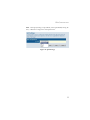
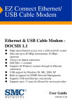
1
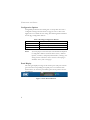
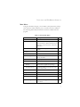
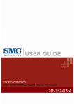
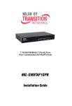
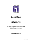
EZ Switch 10/100/1000
Web-Managed Smart Switch
◆
◆
◆
◆
◆
◆
◆
◆
User friendly web management interface
Supports Qos, VLANs and Trunk configuration
Automatic MDI/MDI-X operation
Store-and-forward switching ensures error-free
transmission
Half- and full-duplex flow control prevents packets from
being dropped under heavy loading
Plug-and-play—Optional configuration using web
interface
“At-a-glance” LEDs for port and system status
monitoring
Desktop or rack installation
Management Guide
SMCGS16-Smart
SMCGS24-Smart
EZ Switch 10/100/1000
Management Guide
From SMC’s EZ line of low-cost workgroup LAN solutions
38 Tesla
Irvine, CA 92618
Phone: (949) 679-8000
August 2005
Pub. # 149100007600H
Information furnished by SMC Networks, Inc. (SMC) is believed to be
accurate and reliable. However, no responsibility is assumed by SMC for its
use, nor for any infringements of patents or other rights of third parties
which may result from its use. No license is granted by implication or
otherwise under any patent or patent rights of SMC. SMC reserves the
right to change specifications at any time without notice.
Copyright © 2005 by
SMC Networks, Inc.
38 Tesla
Irvine, CA 92618
All rights reserved. Printed in Taiwan
Trademarks:
SMC is a registered trademark; and EZ Switch, TigerStack and TigerSwitch are trademarks of SMC
Networks, Inc. Other product and company names are trademarks or registered trademarks of their
respective holders.
LIMITED WARRANTY
Limited Warranty Statement: SMC Networks, Inc. (“SMC”) warrants its products to be
free from defects in workmanship and materials, under normal use and service, for the
applicable warranty term. All SMC products carry a standard 90-day limited warranty from
the date of purchase from SMC or its Authorized Reseller. SMC may, at its own discretion,
repair or replace any product not operating as warranted with a similar or functionally
equivalent product, during the applicable warranty term. SMC will endeavor to repair or
replace any product returned under warranty within 30 days of receipt of the product.
The standard limited warranty can be upgraded to a Limited Lifetime* warranty by registering
new products within 30 days of purchase from SMC or its Authorized Reseller. Registration
can be accomplished via the enclosed product registration card or online via the SMC Web
site. Failure to register will not affect the standard limited warranty. The Limited Lifetime
warranty covers a product during the Life of that Product, which is defined as the period of
time during which the product is an “Active” SMC product. A product is considered to be
“Active” while it is listed on the current SMC price list. As new technologies emerge, older
technologies become obsolete and SMC will, at its discretion, replace an older product in its
product line with one that incorporates these newer technologies. At that point, the obsolete
product is discontinued and is no longer an “Active” SMC product. A list of discontinued
products with their respective dates of discontinuance can be found at:
http://www.smc.com/index.cfm?action=customer_service_warranty.
All products that are replaced become the property of SMC. Replacement products may be
either new or reconditioned. Any replaced or repaired product carries either a 30-day limited
warranty or the remainder of the initial warranty, whichever is longer. SMC is not responsible
for any custom software or firmware, configuration information, or memory data of
Customer contained in, stored on, or integrated with any products returned to SMC pursuant
to any warranty. Products returned to SMC should have any customer-installed accessory or
add-on components, such as expansion modules, removed prior to returning the product for
replacement. SMC is not responsible for these items if they are returned with the product.
Customers must contact SMC for a Return Material Authorization number prior to returning
any product to SMC. Proof of purchase may be required. Any product returned to SMC
without a valid Return Material Authorization (RMA) number clearly marked on the outside
of the package will be returned to customer at customer’s expense. For warranty claims within
North America, please call our toll-free customer support number at (800) 762-4968.
Customers are responsible for all shipping charges from their facility to SMC. SMC is
responsible for return shipping charges from SMC to customer.
i
WARRANTIES EXCLUSIVE: IF AN SMC PRODUCT DOES NOT OPERATE AS
WARRANTED ABOVE, CUSTOMER’S SOLE REMEDY SHALL BE REPAIR OR
REPLACEMENT OF THE PRODUCT IN QUESTION, AT SMC’S OPTION. THE
FOREGOING WARRANTIES AND REMEDIES ARE EXCLUSIVE AND ARE IN
LIEU OF ALL OTHER WARRANTIES OR CONDITIONS, EXPRESS OR IMPLIED,
EITHER IN FACT OR BY OPERATION OF LAW, STATUTORY OR OTHERWISE,
INCLUDING WARRANTIES OR CONDITIONS OF MERCHANTABILITY AND
FITNESS FOR A PARTICULAR PURPOSE. SMC NEITHER ASSUMES NOR
AUTHORIZES ANY OTHER PERSON TO ASSUME FOR IT ANY OTHER
LIABILITY IN CONNECTION WITH THE SALE, INSTALLATION,
MAINTENANCE OR USE OF ITS PRODUCTS. SMC SHALL NOT BE LIABLE
UNDER THIS WARRANTY IF ITS TESTING AND EXAMINATION DISCLOSE THE
ALLEGED DEFECT IN THE PRODUCT DOES NOT EXIST OR WAS CAUSED BY
CUSTOMER’S OR ANY THIRD PERSON’S MISUSE, NEGLECT, IMPROPER
INSTALLATION OR TESTING, UNAUTHORIZED ATTEMPTS TO REPAIR, OR
ANY OTHER CAUSE BEYOND THE RANGE OF THE INTENDED USE, OR BY
ACCIDENT, FIRE, LIGHTNING, OR OTHER HAZARD.
LIMITATION OF LIABILITY: IN NO EVENT, WHETHER BASED IN CONTRACT
OR TORT (INCLUDING NEGLIGENCE), SHALL SMC BE LIABLE FOR
INCIDENTAL, CONSEQUENTIAL, INDIRECT, SPECIAL, OR PUNITIVE
DAMAGES OF ANY KIND, OR FOR LOSS OF REVENUE, LOSS OF BUSINESS, OR
OTHER FINANCIAL LOSS ARISING OUT OF OR IN CONNECTION WITH THE
SALE, INSTALLATION, MAINTENANCE, USE, PERFORMANCE, FAILURE, OR
INTERRUPTION OF ITS PRODUCTS, EVEN IF SMC OR ITS AUTHORIZED
RESELLER HAS BEEN ADVISED OF THE POSSIBILITY OF SUCH DAMAGES.
SOME STATES DO NOT ALLOW THE EXCLUSION OF IMPLIED WARRANTIES
OR THE LIMITATION OF INCIDENTAL OR CONSEQUENTIAL DAMAGES FOR
CONSUMER PRODUCTS, SO THE ABOVE LIMITATIONS AND EXCLUSIONS
MAY NOT APPLY TO YOU. THIS WARRANTY GIVES YOU SPECIFIC LEGAL
RIGHTS, WHICH MAY VARY FROM STATE TO STATE. NOTHING IN THIS
WARRANTY SHALL BE TAKEN TO AFFECT YOUR STATUTORY RIGHTS.
* SMC will provide warranty service for one year following discontinuance from the active
SMC price list. Under the limited lifetime warranty, internal and external power supplies, fans,
and cables are covered by a standard one-year warranty from date of purchase.
SMC Networks, Inc.
38 Tesla
Irvine, CA 92618
ii
COMPLIANCES
COMPLIANCES
FCC - Class A
This equipment has been tested and found to comply with the limits for a Class A digital
device, pursuant to Part 15 of the FCC Rules. These limits are designed to provide reasonable
protection against harmful interference in a residential installation. This equipment generates,
uses and can radiate radio frequency energy and, if not installed and used in accordance with
instructions, may cause harmful interference to radio communications. However, there is no
guarantee that the interference will not occur in a particular installation. If this equipment
does cause harmful interference to radio or television reception, which can be determined by
turning the equipment off and on, the user is encouraged to try to correct the interference by
one or more of the following measures:
• Reorient the receiving antenna
• Increase the separation between the equipment and receiver
• Connect the equipment into an outlet on a circuit different from that to which the receiver
is connected
• Consult the dealer or an experienced radio/TV technician for help
EC Conformance Declaration - Class A
SMC contact for these products in Europe is:
SMC Networks Europe,
Edificio Conata II,
Calle Fructuós Gelabert 6-8, 2o, 4a,
08970 - Sant Joan Despí,
Barcelona, Spain.
This information technology equipment complies with the requirements of the Council
Directive 89/336/EEC on the Approximation of the laws of the Member States relating to
Electromagnetic Compatibility and 73/23/EEC for electrical equipment used within certain
voltage limits and the Amendment Directive 93/68/EEC. For the evaluation of the
compliance with these Directives, the following standards were applied:
RFI Emission:
• Limit class A according to EN 55022:1998, IEC 60601-1-2 (EMC,
medical)
• Limit class A for harmonic current emission according to
EN 61000-3-2/1995
• Limitation of voltage fluctuation and flicker in low-voltage supply system
according to EN 61000-3-3/1995
Immunity:
• Product family standard according to EN 55024:1998
iii
COMPLIANCES
• Electrostatic Discharge according to EN 61000-4-2:1995
(Contact Discharge: ±4 kV, Air Discharge: ±8 kV)
• Radio-frequency electromagnetic field according to EN 61000-4-3:1996
(80 - 1000 MHz with 1 kHz AM 80% Modulation: 3 V/m)
• Electrical fast transient/burst according to EN 61000-4-4:1995 (AC/DC
power supply: ±1 kV, Data/Signal lines: ±0.5 kV)
• Surge immunity test according to EN 61000-4-5:1995
(AC/DC Line to Line: ±1 kV, AC/DC Line to Earth: ±2 kV)
• Immunity to conducted disturbances, Induced by radio-frequency fields:
EN 61000-4-6:1996 (0.15 - 80 MHz with
1 kHz AM 80% Modulation: 3 V/m)
• Power frequency magnetic field immunity test according to
EN 61000-4-8:1993 (1 A/m at frequency 50 Hz)
• Voltage dips, short interruptions and voltage variations immunity test
according to EN 61000-4-11:1994 (>95% Reduction @10 ms, 30%
Reduction @500 ms, >95% Reduction @5000 ms)
LVD:
• EN 60950-1:2001
Industry Canada - Class A
This digital apparatus does not exceed the Class A limits for radio noise emissions from
digital apparatus as set out in the interference-causing equipment standard entitled “Digital
Apparatus,” ICES-003 of the Department of Communications.
Cet appareil numérique respecte les limites de bruits radioélectriques applicables aux appareils
numériques de Classe A prescrites dans la norme sur le matériel brouilleur: “Appareils
Numériques,” NMB-003 édictée par le ministère des Communications.
Japan VCCI Class A
iv
COMPLIANCES
Please read the following safety information carefully
before installing the Switch:
WARNING: Installation and removal of the unit must be carried out by
qualified personnel only.
• This guide is intended for use by network administrators who are
responsible for setting up and installing network equipment;
consequently it assumes a basic working knowledge of LANs (Local Area
Networks).
• The unit must be connected to an earthed (grounded) outlet to comply
with international safety standards.
• Do not connect the unit to an A.C. outlet (power supply) without an
earth (ground) connection.
• The appliance coupler (the connector to the unit and not the wall plug)
must have a configuration for mating with an EN 60320/IEC 320
appliance inlet.
• The socket outlet must be near to the unit and easily accessible. You can
only remove power from the unit by disconnecting the power cord from
the outlet.
• This unit operates under SELV (Safety Extra Low Voltage) conditions
according to IEC 60950. The conditions are only maintained if the
equipment to which it is connected also operates under SELV
conditions.
v
COMPLIANCES
France and Peru only
This unit cannot be powered from IT† supplies. If your supplies are of IT type, this unit must
be powered by 230 V (2P+T) via an isolation transformer ratio 1:1, with the secondary connection point labelled Neutral, connected directly to earth (ground).
†
Impédance à la terre
Power Cord Set
U.S.A. and Canada
The cord set must be UL-approved and CSA certified.
The minimum specifications for the flexible cord are:
- No. 18 AWG - not longer than 2 meters, or 16 AWG.
- Type SV or SJ
- 3-conductor
The cord set must have a rated current capacity of at least 10 A.
The attachment plug must be an earth-grounding type with NEMA
5-15P (15 A, 125 V) or NEMA 6-15P (15 A, 250 V) configuration.
Denmark
The supply plug must comply with Section 107-2-D1, Standard
DK2-1a or DK2-5a.
Switzerland
The supply plug must comply with SEV/ASE 1011.
U.K.
The supply plug must comply with BS1363 (3-pin 13 A) and be fitted with a 5 A fuse which complies with BS1362.
The mains cord must be <HAR> or <BASEC> marked and be of
type HO3VVF3GO.75 (minimum).
Europe
The supply plug must comply with CEE7/7 (“SCHUKO”).
The mains cord must be <HAR> or <BASEC> marked and be of
type HO3VVF3GO.75 (minimum).
IEC-320 receptacle.
Veuillez lire à fond l'information de la sécurité suivante
avant d'installer le Switch:
AVERTISSEMENT: L’installation et la dépose de ce groupe doivent être
confiés à un personnel qualifié.
• Ne branchez pas votre appareil sur une prise secteur (alimentation
électrique) lorsqu'il n'y a pas de connexion de mise à la terre (mise à la
masse).
vi
COMPLIANCES
• Vous devez raccorder ce groupe à une sortie mise à la terre (mise à la
masse) afin de respecter les normes internationales de sécurité.
• Le coupleur d’appareil (le connecteur du groupe et non pas la prise
murale) doit respecter une configuration qui permet un branchement sur
une entrée d’appareil EN 60320/IEC 320.
• La prise secteur doit se trouver à proximité de l’appareil et son accès doit
être facile. Vous ne pouvez mettre l’appareil hors circuit qu’en
débranchant son cordon électrique au niveau de cette prise.
• L’appareil fonctionne à une tension extrêmement basse de sécurité qui
est conforme à la norme IEC 60950. Ces conditions ne sont maintenues
que si l’équipement auquel il est raccordé fonctionne dans les mêmes
conditions.
France et Pérou uniquement:
Ce groupe ne peut pas être alimenté par un dispositif à impédance à la terre. Si vos alimentations sont du type impédance à la terre, ce groupe doit être alimenté par une tension de 230 V
(2 P+T) par le biais d’un transformateur d’isolement à rapport 1:1, avec un point secondaire
de connexion portant l’appellation Neutre et avec raccordement direct à la terre (masse).
Cordon électrique - Il doit être agréé dans le pays d’utilisation
Etats-Unis et Canada:
Le cordon doit avoir reçu l’homologation des UL et un certificat de
la CSA.
Les spe'cifications minimales pour la corde flexible sont AWG No.
18, ou AWG No. 16 pour une longueur infe'rieure a` 2 me'tres:
- type SV ou SJ
- 3 conducteurs
Le cordon doit être en mesure d’acheminer un courant nominal
d’au moins 10 A.
La prise femelle de branchement doit être du type à mise à la terre
(mise à la masse) et respecter la configuration NEMA 5-15P (15 A,
125 V) ou NEMA 6-15P (15 A, 250 V).
Danemark:
La prise mâle d’alimentation doit respecter la section 107-2 D1 de
la norme DK2 1a ou DK2 5a.
vii
COMPLIANCES
Cordon électrique - Il doit être agréé dans le pays d’utilisation
Suisse:
La prise mâle d’alimentation doit respecter la norme SEV/ASE
1011.
Europe
La prise secteur doit être conforme aux normes CEE 7/7 (“SCHUKO”)
LE cordon secteur doit porter la mention <HAR> ou <BASEC>
et doit être de type HO3VVF3GO.75 (minimum).
Bitte unbedingt vor dem Einbauen des RPU die
folgenden Sicherheitsanweisungen durchlesen:
WARNUNG: Die Installation und der Ausbau des Geräts darf nur durch
Fachpersonal erfolgen.
• Diese Anleitung ist fr die Benutzung durch Netzwerkadministratoren
vorgesehen, die fr die Installation und das einstellen von
Netzwerkkomponenten verantwortlich sind; sie setzt Erfahrung bei der
Arbeit mit LANs (Local Area Networks) voraus.
• Das Gerät sollte nicht an eine ungeerdete Wechselstromsteckdose
angeschlossen werden.
• Das Gerät muß an eine geerdete Steckdose angeschlossen werden,
welche die internationalen Sicherheitsnormen erfüllt.
• Der Gerätestecker (der Anschluß an das Gerät, nicht der
Wandsteckdosenstecker) muß einen gemäß EN 60320/IEC 320
konfigurierten Geräteeingang haben.
• Die Netzsteckdose muß in der Nähe des Geräts und leicht zugänglich
sein. Die Stromversorgung des Geräts kann nur durch Herausziehen des
Gerätenetzkabels aus der Netzsteckdose unterbrochen werden.
• Der Betrieb dieses Geräts erfolgt unter den SELV-Bedingungen
(Sicherheitskleinstspannung) gemäß IEC 60950. Diese Bedingungen sind
nur gegeben, wenn auch die an das Gerät angeschlossenen Geräte unter
SELV-Bedingungen betrieben werden
viii
COMPLIANCES
Stromkabel. Dies muss von dem Land, in dem es benutzt wird geprüft werden:
Schweiz
Dieser Stromstecker muß die SEV/ASE 1011Bestimmungen einhalten.
Europe
Das Netzkabel muß vom Typ HO3VVF3GO.75 (Mindestanforderung) sein und die Aufschrift <HAR> oder <BASEC>
tragen.
Der Netzstecker muß die Norm CEE 7/7 erfüllen (”SCHUKO”).
Warnings and Cautionary Messages
Warning:
This product does not contain any serviceable user parts.
Warning:
Installation and removal of the unit must be carried out by qualified personnel
only.
Warning:
When connecting this device to a power outlet, connect the field ground lead
on the tri-pole power plug to a valid earth ground line to prevent electrical
hazards.
Caution:
Wear an anti-static wrist strap or take other suitable measures to prevent
electrostatic discharge when handling this equipment.
Caution:
Do not plug a phone jack connector in the RJ-45 port. This may damage this
device. Les raccordeurs ne sont pas utilisé pour le système téléphonique!
Caution:
Use only twisted-pair cables with RJ-45 connectors that conform to FCC
standards.
Warnings (in German)
Achtung:
Dieses Produkt enthält keine Teile, die eine Wartung vom Benutzer benötigen.
Achtung:
Installation und Deinstallation des Gerätes müssen von qualifiziertem
Servicepersonal durchgeführt werden.
Achtung:
Wenn das Gerät an eine Steckdose angeschlossen wird, muß der Masseanschluß
am dreipoligen Netzstecker mit Schutzerde verbunden werden, um elektrische
Gefahren zu vermeiden.
ix
COMPLIANCES
Environmental Statement
The manufacturer of this product endeavours to sustain an environmentally-friendly policy
throughout the entire production process. This is achieved though the following means:
•
•
•
•
•
•
Adherence to national legislation and regulations on environmental production standards.
Conservation of operational resources.
Waste reduction and safe disposal of all harmful un-recyclable by-products.
Recycling of all reusable waste content.
Design of products to maximize recyclables at the end of the product’s life span.
Continual monitoring of safety standards.
End of Product Life Span
This product is manufactured in such a way as to allow for the recovery and disposal of all included
electrical components once the product has reached the end of its life.
Manufacturing Materials
There are no hazardous nor ozone-depleting materials in this product.
Documentation
All printed documentation for this product uses biodegradable paper that originates from
sustained and managed forests. The inks used in the printing process are non-toxic.
Purpose
This guide details the hardware features of the switch, including Its physical and
performance-related characteristics, and how to install the switch.
Audience
The guide is intended for use by network administrators who are responsible for installing and
setting up network equipment; consequently, it assumes a basic working knowledge of LANs
(Local Area Networks).
Diese Anleitung ist für die Benutzung durch Netzwerkadministratoren vorgesehen, die für die
Installation und das einstellen von Netzwerkkomponenten verantwortlich sind; sie setzt
Erfahrung bei der Arbeit mit LANs (Local Area Networks) voraus.
x
TABLE OF CONTENTS
Introduction . . . . . . . . . . . . . . . . . . . . . . . . . . . . . . . . . . . 1
Features and Benefits . . . . . . . . . . . . . . . . . . . . . . . . . . . . . . . . . . . . . . . . . . 1
Initial Configuration . . . . . . . . . . . . . . . . . . . . . . . . . . . . 2
Configuring the Switch . . . . . . . . . . . . . . . . . . . . . . . . . . 4
Using the Web Interface . . . . . . . . . . . . . . . . . . . . . . . . . . . . . . . . . . . . . . . 4
Navigating the Web Browser Interface . . . . . . . . . . . . . . . . . . . . . . . . . . . . 5
Home Page . . . . . . . . . . . . . . . . . . . . . . . . . . . . . . . . . . . . . . . . . . . . 5
Configuration Options . . . . . . . . . . . . . . . . . . . . . . . . . . . . . . . . . . . 6
Panel Display . . . . . . . . . . . . . . . . . . . . . . . . . . . . . . . . . . . . . . . . . . . 6
Main Menu . . . . . . . . . . . . . . . . . . . . . . . . . . . . . . . . . . . . . . . . . . . . 7
Web Configuration . . . . . . . . . . . . . . . . . . . . . . . . . . . . . . . . . . . . . . . . . . . . 8
Displaying Status Overview . . . . . . . . . . . . . . . . . . . . . . . . . . . . . . . 8
Showing Port Statistics . . . . . . . . . . . . . . . . . . . . . . . . . . . . . . . . . . 12
Displaying System Name . . . . . . . . . . . . . . . . . . . . . . . . . . . . . . . . 15
Setting the Switch’s IP Address . . . . . . . . . . . . . . . . . . . . . . . . . . 16
Configuring the Logon Password . . . . . . . . . . . . . . . . . . . . . . . . . 17
Tools . . . . . . . . . . . . . . . . . . . . . . . . . . . . . . . . . . . . . . . . . . . . . . . . 18
Register Product . . . . . . . . . . . . . . . . . . . . . . . . . . . . . . . . . . . . . . . 20
Port Configuration . . . . . . . . . . . . . . . . . . . . . . . . . . . . . . . . . . . . . 20
Configuring Rate Limits . . . . . . . . . . . . . . . . . . . . . . . . . . . . . . . . . 21
Port Broadcast Control . . . . . . . . . . . . . . . . . . . . . . . . . . . . . . . . . . 23
Port Mirroring . . . . . . . . . . . . . . . . . . . . . . . . . . . . . . . . . . . . . . . . . 24
Trunks Membership . . . . . . . . . . . . . . . . . . . . . . . . . . . . . . . . . . . . 25
Trunk Configuration . . . . . . . . . . . . . . . . . . . . . . . . . . . . . . . . . . . . 26
Trunk Rate Limit . . . . . . . . . . . . . . . . . . . . . . . . . . . . . . . . . . . . . . 27
VLAN Settings . . . . . . . . . . . . . . . . . . . . . . . . . . . . . . . . . . . . . . . . 28
QOS Settings . . . . . . . . . . . . . . . . . . . . . . . . . . . . . . . . . . . . . . . . . . 31
Troubleshooting . . . . . . . . . . . . . . . . . . . . . . . . . . . . . . 34
Diagnosing Switch Indicators . . . . . . . . . . . . . . . . . . . . . . . . . . . . . . . . . . 34
Changing PC’s IP Address . . . . . . . . . . . . . . . . . . . . . . 36
vii
Product Specifications . . . . . . . . . . . . . . . . . . . . . . . . . .37
EZ Switch 10/100/1000 . . . . . . . . . . . . . . . . . . . . . . . . . . . . . . . . . . . . . . 37
viii
FEATURES AND BENEFITS
INTRODUCTION
The EZ Switch 10/100/1000, SMCGS16-Smart and SMCGS24-Smart, are
high performance web managed smart switches for delivering
performance and control to your network. They provide 16/24
full-duplex 1000BASE-T ports that significantly improve network
performance and boost throughput using Smart features configured on the
web interface. With 32/48 Gigabits of throughput bandwidth, these
switches provide the quickest solution to meeting the growing demands on
your network.
Features and Benefits
•
•
•
•
User friendly web management interface
Supports Qos, VLANs and Trunk configuration
Store-and-forward switching ensures error-free transmission
Half- and full-duplex flow control prevents packets from being dropped
under heavy loading
• Plug-and-play—Optional configuration using web interface
• “At-a-glance” LEDs for port and system status monitoring
• Desktop or rack installation
1
INITIAL CONFIGURATION
INITIAL CONFIGURATION
To make use of the management features of your SMC Smart Switch you
must first give it an IP address. For simplicity, this should be done before
you permanently install the switch in the network.
The following procedure is recommended:
1. Place your Smart Switch close to the PC that you will use to configure
it. It will help if you can see the front panel of the switch while
working on your PC.
2. Connect the Ethernet port of your PC to any port on the front panel
of your Smart Switch, start your PC (if it is not already running),
connect power to the switch and, when your PC has finished its
start-up sequence, verify that you have a link by checking the LEDs on
the front-panel of the switch (see the Hardware Description for more
information).
3. The default IP address of the switch is 192.168.2.10 and the subnet
mask is 255.255.255.0. If your PC has a different address from the
switch but is on the same subnet (i.e. the PC and switch both have
addresses that start 192.168.2.x but are different thereafter) you can
skip directly to step 4. Otherwise you will have to set your PC’s IP
address manually. If you are unfamiliar with this process, please refer
to the “Changing PC’s IP Address” on page 7.
4. After changing your PC's IP address, open your web browser and
enter the address http://192.168.2.10. If your PC is properly
configured, you will see the login page of your Smart Switch. If you do
not see the login page, please check your settings and repeat step 3.
5. Enter the password (the default is “smcadmin”) and click on the Login
button.
2
FEATURES AND BENEFITS
6. Click on the SYSTEM menu-choice then click on LAN Settings when
it appears. On the LAN Settings page, enter the IP address, Subnet
Mask and Gateway IP Address for the switch then click on the APPLY
button.
No other configuration changes are required at this stage but it is
recommended that you change the administrator’s password before
logging out. To change the password click on the SYSTEM¬ Password
menu-choice and fill in all the fields on the Password Settings page before
clicking on the APPLY button. (see “Setting the Switch’s IP Address” on
page 16 for more information)
3
CONFIGURING THE SWITCH
CONFIGURING THE SWITCH
Using the Web Interface
This switch provides an embedded HTTP web agent. Using a web browser
you can configure the switch and view statistics to monitor network
activity. The web agent can be accessed by any computer on the network
using a standard web browser (Internet Explorer 5.5 or above, or Mozilla
Firefox 1.0 or above).
Prior to accessing the switch from a web browser, be sure you have first
performed the following tasks:
1. Configure the switch with a valid IP address, subnet mask, and default
gateway. (Default: 192.168.2.10/255.255.255.0/0.0.0.0)
(See “Initial Configuration” on page 2.)
2. Set a new password using the web interface. (Default: “smcadmin”).
Access to the web interface is controlled by the password.
(See “Configuring the Logon Password” on page 15.)
Note:
4
If, at any point, you cannot remember the switch's IP address,
you can restore the original settings by following the procedure
described in the "Troubleshooting" section.
NAVIGATING THE WEB BROWSER INTERFACE
Navigating the Web Browser Interface
To access the web-browser interface you must first enter a password. The
user has Read/Write access to all configuration parameters and statistics.
The default password for the switch is “smcadmin.” If user input is not
detected within five minutes, the current session will be terminated.
Home Page
When your web browser connects with the switch’s web agent, the home
page is displayed as shown below. The home page displays the Main Menu
on the left side of the screen and System Information on the right side.
The Main Menu links are used to navigate to other menus, and display
configuration parameters and statistics.
Figure 1 Home Page
Note: The examples in this chapter are based on the SMCGS16-Smart.
Other than the number of fixed ports, there are no major
differences between the SMCGS16-Smart and SMCGS24-Smart.
5
CONFIGURING THE SWITCH
Configuration Options
Configurable parameters have a dialog box or a drop-down list. Once a
configuration change has been made on a page, be sure to click on the
Apply button to confirm the new setting. The following table summarizes
the web page configuration buttons.
Table 2 Web Page Configuration Buttons
Button
Action
Apply
Sets specified values to the system.
Cancel
Discards all changes and restores current values.
Help
Links directly to web help.
Notes:
To ensure proper screen refresh, be sure that Internet Explorer
is configured as follows: Under the menu “Tools / Internet
Options / General / Temporary Internet Files / Settings,” the
setting for item “Check for newer versions of stored pages”
should be “Every visit to the page.”
Panel Display
The web agent displays an image of the switch’s ports. The port will turn
green when the corresponding front-panel port is in connection with
another device. To show the port number, place mouse pointer onto the
intended port.
Figure 2 Front Panel Indicators
6
NAVIGATING THE WEB BROWSER INTERFACE
Main Menu
Using the onboard web agent, you can define system parameters, manage
and control the switch, and all its ports, or monitor network conditions.
The following table briefly describes the selections available from this
program.
Table 2-1 Switch Main Menu
Menu
Description
STATUS
Page
6
Overview
Provides basic system description, including
system information, address information, port
information, trunk information, and VLAN
information.
Statistics
Shows statistics for port, interface, and
RMON.
SYSTEM
6
10
13
Name
Shows the name of the switch.
13
LAN Settings
Sets LAN IP address, subnet mask, and
gateway IP address.
14
Password
Changes password.
15
Tools
16
Restore to Factory
Defaults
Force the Switch to perform a power reset
and restore the original factory settings.
16
Upgrade Firmware
Upgrade the Switch system firmware using a
file provided by SMC.
17
Restart
Restarts the switch.
17
Registers the switch online.
18
Register Product
PORTS
18
Settings
Configure the speed and duplex mode of the
port.
18
Rate Limiting
Sets the rate limiting parameters for each port
on the Switch
19
7
CONFIGURING THE SWITCH
Table 2-1 Switch Main Menu (Continued)
Menu
Description
Page
Broadcast Control
Sets the broadcast storm control parameters
for every port on the Switch.
21
Port Mirroring
Sets up the port mirroring features of the
switch to enable traffic monitoring.
22
TRUNKS
23
Membership
Specifies ports to group into static trunks
Settings
Configures trunk connection settings
24
Rate Limiting
Sets the rate limiting parameters for each
Trunk configured on the Switch.
25
VLANS
VLAN Settings
26
Configures the VLANs on the switch for both
Ports and Trunks
QOS
Settings
LOGOUT
24
26
29
Sets the priority of packets within the switch.
29
Quits to the Login page.
Web Configuration
Displaying Status Overview
You can easily identify the system by displaying the device name, location
and contact information.
Field Attributes
System Information
• System Name – Name assigned to the switch system.
• Number of Ports – Number of built-in ports.
• Hardware Version – Hardware version of the main board.
• Code Version – Version number of the code.
• Serial Number – The serial number of the switch.
8
WEB CONFIGURATION
Address Information
• Management VLAN – ID of the configured VLAN (this is set to 1 and
cannot be changed) all ports on the unit are members of VLAN 1. The
management station must always be attached to a port on VLAN 1.
• IP Address – Address of the VLAN to which the management station
is attached. (Note that the management station must always be on VLAN
1) Valid IP addresses consist of four numbers, 0 to 255, separated by
periods.
• Subnet Mask – This mask identifies the host address bits used for
routing to specific subnets. (Default: 255.255.255.0)
• Gateway IP Address – IP address of the gateway router between the
stack and management stations that exist on other network segments.
(Default: 0.0.0.0)
• MAC Address – The physical layer address.
Port Information
• Type – Indicates the port type.
• Link Status – Indicates if the link is Up or Down.
• Speed/Duplex Status – Shows the current speed and duplex mode.
Displays a number, the speed in Mbps, followed by either "fdx" for
full-duplex or "hdx" for half-duplex.
• Flow Control Status – Indicates whether flow control is enabled or
disabled.
• Autonegotiation – Shows if auto-negotiation is enabled or disabled.
• Frame Type – Either "Tagged" or "All". "Tagged" means that the port
will only send and receive VLAN-tagged packets. When set to "All", the
port will also send and receive untagged packets.
• PVID – VLAN ID assigned to untagged frames received on the
interface. (Default: 1)
Trunk Information
• Trunk – The trunk label. "T1" through "T8" are used as trunk labels.
• Type – All trunks and ports on this switch are 10/100/1000M
• Trunk Status – An indication of the speed and duplex setting of the
9
CONFIGURING THE SWITCH
trunk. This is a number, the speed in Mbps, followed by either “Full” for
full-duplex or “Half” for half-duplex. This can be changed on the
TRUNKS > Settings page.
• Ports – The ports that are members of the trunk.
VLAN Inoformation
• VLAN ID – A number in the range 1 - 4094 which identifies the VLAN.
• VLAN Member – A list of the ports that are members of the VLAN.
By default, all ports are members of VLAN 1.
10
WEB CONFIGURATION
Web – Click STATUS, Overview.
Figure 3 Switch Information
11
CONFIGURING THE SWITCH
Showing Port Statistics
You can display statistics on network traffic from the ports. These statistics
can be used to identify potential problems with the switch (such as a faulty
port or unusually heavy loading). All values displayed have been
accumulated since the last system reboot, but can be reset to zero by
clicking the CLEAR button. The current statistics are not displayed until
you click the REFRESH button.
Table 4 Port Statistics
Parameter
Description
Interface Statistics
Received Octets
The total number of octets received on the interface,
including framing characters.
Received Unicast Packets
The number of subnetwork-unicast packets delivered
to a higher-layer protocol.
Received Errors
The number of inbound packets that contained errors
preventing them from being deliverable to a
higher-layer protocol.
Transmitted Multicast
Packets
The total number of packets that higher-level
protocols requested be transmitted, and which were
addressed to a multicast address at this sub-layer,
including those that were discarded or not sent.
Transmitted Broadcast
Packets
The total number of packets that higher-level
protocols requested be transmitted, and which were
addressed to a broadcast address at this sub-layer,
including those that were discarded or not sent.
Received High Priority
Packets
The total number of received packets that set as High
Priority in the QoS settings.
Transmitted High Priority The total number of transmitted packets that set as
Packets
High Priority in the QoS settings.
Received Multicast Packets The number of packets, delivered by this sub-layer to
a higher (sub-)layer, which were addressed to a
multicast address at this sub-layer.
12
WEB CONFIGURATION
Table 4 Port Statistics (Continued)
Parameter
Description
Received Broadcast
Packets
The number of packets, delivered by this sub-layer to
a higher (sub-)layer, which were addressed to a
broadcast address at this sub-layer.
Transmitted Octets
The total number of octets transmitted out of the
interface, including framing characters.
Transmitted Unicast
Packets
The total number of packets that higher-level
protocols requested be transmitted to a
subnetwork-unicast address, including those that
were discarded or not sent.
Transmitted Errors
The number of outbound packets that could not be
transmitted because of errors.
Received Normal Priority
Packets
The total number of received packets that set as High
Priority in the QoS settings.
Transmitted Normal
Priority Packets
The total number of transmitted packets that set as
High Priority in the QoS settings.
RMON Statistics
Drop Events
The total number of events in which packets were
dropped due to lack of resources.
Received Frames
The total number of frames (bad, broadcast and
multicast) received.
Multicast Frames
The total number of good frames received that were
directed to this multicast address.
Undersize Frames
The total number of frames received that were less
than 64 octets long (excluding framing bits, but
including FCS octets) and were otherwise well
formed.
Fragments
The total number of frames received that were less
than 64 octets in length (excluding framing bits, but
including FCS octets) and had either an FCS or
alignment error.
Collisions
The best estimate of the total number of collisions on
this Ethernet segment.
13
CONFIGURING THE SWITCH
Table 4 Port Statistics (Continued)
14
Parameter
Description
Received Bytes
Total number of bytes of data received on the
network. This statistic can be used as a reasonable
indication of Ethernet utilization.
Broadcast Frames
The total number of good frames received that were
directed to the broadcast address. Note that this does
not include multicast packets.
CRC/Alignment Errors
The number of CRC/alignment errors (FCS or
alignment errors).
Oversize Frames
The total number of frames received that were longer
than 1518 octets (excluding framing bits, but
including FCS octets) and were otherwise well
formed.
Jabbers
The total number of frames received that were longer
than 1518 octets (excluding framing bits, but
including FCS octets), and had either an FCS or
alignment error.
64 Bytes Frames
The total number of frames (including bad packets)
received and transmitted that were 64 octets in length
(excluding framing bits but including FCS octets).
65-127 Byte Frames
128-255 Byte Frames
256-511 Byte Frames
512-1023 Byte Frames
1024-1518 Byte Frames
1519-1536 Byte Frames
The total number of frames (including bad packets)
received and transmitted where the number of octets
fall within the specified range (excluding framing bits
but including FCS octets).
WEB CONFIGURATION
Web – Click STATUS, Statistics.
Figure 5 Port Statistics
Displaying System Name
You can easily identify the system by displaying the device name.
Field Attributes
• Switch Name – Name assigned to the switch system.
15
CONFIGURING THE SWITCH
Web – Click System, Name.
Figure 6 System Name
Setting the Switch’s IP Address
This section describes how to configure an IP interface for management
access over the network. The IP address for this switch is 192.168.2.10 by
default. To manually configure an address, you need to change the switch’s
default settings (IP address 192.168.2.10 and netmask 255.255.255.0) to
values that are compatible with your network. You may also need to a
establish a default gateway between the switch and management stations
that exist on another network segment.
Field Attributes
•
LAN IP Address – Address of the VLAN interface that is allowed
management access. Valid IP addresses consist of four numbers, 0 to
255, separated by periods. (Default : 192.168.2.10)
•
Subnet Mask – This mask identifies the host address bits used for
routing to specific subnets. (Default: 255.255.255.0)
•
Gateway IP Address – IP address of the gateway router between this
device and management stations that exist on other network segments.
(Default: 0.0.0.0)
Note:
16
If, at any point, you cannot remember the switch's IP address,
you can restore the original settings by following the procedure
described in the "Troubleshooting" section.
WEB CONFIGURATION
Manual Configuration
Web – Click System, LAN Settings. Enter the IP address, subnet mask and
gateway, then click APPLY.
Figure 7 LAN Settings
Configuring the Logon Password
The administrator has write access for all parameters governing the
onboard agent. You should therefore assign a new administrator password
as soon as possible, and store it in a safe place.
Field Attributes
•
Password – Specifies the user password.
(Range: 1-16 characters plain text, case sensitive)
Note:
If, at any point, you cannot remember the password, you can
restore the original settings by following the procedure described
in the "Troubleshooting" section.
17
CONFIGURING THE SWITCH
Web – Click System, Password. To change the password for the
administrator, enter current password, the new password, confirm it by
entering it again, then click APPLY.
Figure 8 Password Settings
Tools
On Tools page, you can restore the switch to default settings, upgrade the
firmware of the switch, or restart the switch.
Restore to Factory Defaults
Force the Switch to restore the original factory settings. To reset the
switch, select "Reset to Factory Defaults" from the drop-down list and
click APPLY. The LAN IP Address, Subnet Mask and Gateway IP Address
will not be reset.
18
WEB CONFIGURATION
Web – Click System, Tools, Reset to Factory Defaults.
Figure 9 Reset to Factory Defaults
Upgrade Firmware
Upgrades the Switch system firmware using a file provided by SMC. Select
"Upgrade Firmware" from the Tools drop-down list then click on the
"Browse" button to select the firmware file. Finally, press the APPLY
button to upgrade the selected Switch firmware file. You can download
firmware files for your Switch from the Support section of www.smc.com.
Web – Click System, Tools, Reset to Factory Defaults.
Figure 10 Upgrade Firmware
Restart Switch
Web – Click SYSTEM, Tools, Restart Switch. To restart the switch, select
from the Tools drop-down list, and then click APPLY. The reset will be
complete when the user interface displays the login page.
19
CONFIGURING THE SWITCH
Figure 11 Restart Switch
Register Product
Register your product if you have not already done so.
Web – Click System, Register Product. By clicking the Register Now
button you will be taken to the SMC website, where you can enter the
products details.
Figure 12 Register Product
Port Configuration
You can use the Port Configuration page to manually fix the speed, duplex
mode, and flow control.
Field Attributes
• Speed/Duplex – Allows you to manually set the port speed and duplex
mode.
• Flow Control – Allows flow control to be enabled or disabled. When the
box is checked, flow control is enabled.
20
WEB CONFIGURATION
• Trunk – Indicates if a port is a member of a trunk.
Web – Click PORTS, Settings.
Figure 13 Port Configuration
Configuring Rate Limits
This function allows the network manager to control the maximum rate
for traffic transmitted or received on an interface. Rate limiting is
configured on interfaces at the edge of a network to limit traffic into or out
of the switch. Traffic that falls within the rate limit is transmitted, while
packets that exceed the acceptable amount of traffic are dropped.
Rate limiting can be applied to individual ports or trunks. When an
interface is configured with this feature, the traffic rate will be monitored
by the hardware to verify conformity. Non-conforming traffic is dropped,
conforming traffic is forwarded without any changes.
21
CONFIGURING THE SWITCH
The Input/Output Bandwidth Limit field is a type-in box which accepts an
integer number in the range 1 to 100. The number specifies the percentage
of the total input bandwidth of the port that can be used before packets
are dropped or flow-control starts.
Web – Click PORTS, Rate Limiting. This page enables you to set the rate
limiting parameters for each port on the Switch.
Figure 14 Rate Limiting
22
WEB CONFIGURATION
Port Broadcast Control
Broadcast storms may occur when a device on your network is
malfunctioning, or if application programs are not well designed or
properly configured. If there is too much broadcast traffic on your
network, performance can be severely degraded or everything can come to
complete halt.
You can protect your network from broadcast storms by setting a
threshold for broadcast traffic for each port. Any broadcast packets
exceeding the specified threshold will then be dropped.
Field Attributes
• Enable Broadcast Storm Control – Click to select the boxt to enable
Broadcast Storm Control.
• Bandwidth Limit – Threshold as percentage of port bandwidth. This
field accepts an integer value in the range 1 to 100. The value specifies
the percentage of the available input bandwidth that can be made
available for broadcast and multicast traffic. The same percentage
threshold is applied to every port on the switch. When the threshold is
exceeded, packets are dropped, irrespective of the flow control settings.
Web – Click PORTS, Broadcast Control. This page enables you to set the
broadcast storm control parameters for every port on the Switch.
Figure 15 Port Broadcast Control
23
CONFIGURING THE SWITCH
Port Mirroring
You can mirror traffic from any source port to a target port for real-time
analysis. You can then attach a logic analyzer or RMON probe to the target
port and study the traffic crossing the source port in a completely
unobtrusive manner.
Field Attributes
Ports to Mirror
Select the ports that you want to mirror from this section of the page. A
port will be mirrored when the"Mirroring Enabled" check-box is checked.
• Port to Mirror to – The port that will “duplicate” or “mirror” the traffic
on the source port. Only incoming packets can be mirrored. Packets will
be dropped when the available egress bandwidth is less than ingress
bandwidth.
Note: If the total ingress bandwidth exceeds the mirror port's egress
bandwidth, packets will eventually be dropped on ingress to the
switch which means they will not reach the mirror port or their
intended destination port. Input rate-limiting in conjunction with
port flow-control could be used to ensure that the total ingress
bandwidth never exceeds the egress bandwidth.
24
WEB CONFIGURATION
Web – Click PORTS, Port Mirroring.
Figure 16 Port Mirroring
Trunks Membership
This page allows you to create a maximum of eight trunks of up to eight
ports each. The Membership Table has one row for each port and ten
columns. Each row contains nine radio buttons which are used to indicate
which trunk (if any) the port belongs to.
Field Attributes
• Port – The front-panel port-number of the port.
• Not a Trunk Member – If the radio button in this column is selected,
the port is not a member of any trunks. This is the default state.
• Trunk T1-T8 – These columns correspond to the eight trunks that are
supported by the Switch. Clicking on the radio button in any one of these
columns causes the port to become a member of the corresponding
trunk.
25
CONFIGURING THE SWITCH
Web – Click TRUNKS, Membership. Click to select which Trunk member
to which each port belongs.
Figure 17 Trunk Membership
Trunk Configuration
Field Attributes
• Trunk – Indicates trunk identification.
• Speed/Duplex – Allows you to manually set the port speed and duplex
mode for all ports in the trunk.
• Flow Control – Allows flow control to be enabled or disabled. When the
box is checked, flow control is enabled.
• Ports – Indicates which ports belong to the trunk.
26
WEB CONFIGURATION
Web – Click TRUNKS, Settings.
Figure 18 Trunk Configuration
Trunk Rate Limit
This page allows you to change the maximum data-rate into and out of
each trunk on the switch.
Field Attributes
• Trunk – Indicates trunk identification.
• Trunk Speed – Indicates the trunk speed.
• Enable Input Rate Limiting - Click to select the box to enable the
Input Rate Limiting function.
• Input Limit – Enter the desired limit. (% of port speed)
• Enable Output Rate Limiting – Click to select the box to enable the
Output Rate Limiting function.
• Output Limit – Enter the desired limit. (% of port speed)
• Ports – Indicates which ports belong to the trunk.
27
CONFIGURING THE SWITCH
Web – Click TRUNKS, Settings.
Figure 19 Trunk Rate Limiting
VLAN Settings
You can configure VLAN behavior for specific interfaces, including the
default VLAN identifier (PVID) and accepted frame types. This page
allows you to create and delete VLANs (Virtual LANs) and to change the
VLAN membership and behaviour of individual ports. VLANs are
powerful but can be difficult to set up properly. Each row of the table
corresponds to one port or trunk; trunked ports cannot be configured
individually.
Introduction to VLANs
VLANs (or Virtual LANs) are logical partitions of the physical LAN. You
can use VLANs to increase network performance or increase internal
network security.
If the network has adequate performance and security for your current
needs, it is recommended that you leave the VLAN settings in the default
configuration. The default configuration is as follows:
• All ports are members of VLAN 1
• The switch management interface is on VLAN 1 (this cannot be
changed)
• All ports have a Port VLAN ID (PVID) of 1
28
WEB CONFIGURATION
• All ports can send and receive both VLAN-tagged and untagged packets
(i.e. they are hybrid ports)
In the default configuration, any port is able to send traffic to any other
port and a PC connected to any port will be able ro reach the management
interface. Broadcast traffic, for example, will be flooded to all ports on the
switch.
There are three different parameters that can be configured for each port
on the switch; VLAN IDs (VLAN membership), PVID and Packet Type.
Note that the ports within a Trunk cannot be configured individually;
configure the Trunk instead (Trunks are labelled T1 to T8).
Field Attributes
• Port/Trunk – The front-panel port-number of the port or the ID of a
trunk. This cannot be changed.
• VLAN ID – VLAN to which matching protocol traffic is forwarded.
VLAN 1 is a special VLAN; it cannot be deleted and, if there is a
possibility that a port could become isolated, the Web USer-interface will
add the port to VLAN 1. You can add up to seven VLANs to the
configuration of the switch. Each VLAN must be given a VLAN ID in
the range 2-4094. One port can be a member of up to eight VLANs. All
packets travelling through the switch are associated with one and only
one VLAN. If a port is not a member of a VLAN, it cannot send or
receive packets associated with that VLAN. A tagged packet carries its
VLAN ID in the payload of the packet. An untagged packet, received on
a port with Packet Type set to “All,” is associated with the VLAN
identified by the PVID.
• PVID – VLAN ID assigned to untagged frames received on the
interface. The PVID is (Port VLAN ID) is the VLAN ID that is
associated with untagged, ingress packets. It is not possible to remove a
port from VLAN 1 unless its PVID has been changed to something other
than 1. The PVID has no effect on ports that have Packet Type set to
Tagged. (Default: 1)
• Packet Type – Sets the interface to accept all frame types, including
29
CONFIGURING THE SWITCH
tagged or untagged frames, or only tagged frames. When set to receive
all frame types, any received frames that are untagged are assigned to the
default VLAN. PCs should be connected to ports with Packet Type set
to “All”. PCs cannot, in general, send or receive tagged packets. Switches
should be connected to each other with Packet Type set to “Tagged”. If
the Packet Type is set to “All”, the port can accept incoming tagged and
untagged packets. Untagged packets will be associated with the VLAN
identified by the PVID. Tagged packets will be dropped unless the port
is a member of the VLAN identified by the VLAN tag in the packet.
Outgoing packets will be tagged unless the packet's VLAN ID is the
same as the PVID. If the Packet Type is set to “Tagged”, the port will
drop untagged packets and will only send and receive tagged packets.
Tagged packets will be dropped unless the port is a member of the
VLAN identified by the VLAN tag in the packet. The PVID has no
effect in this case.(Option: All, Tagged; Default: All)
Web – Click VLANS, VLAN Settings. Fill in the required settings for each
interface, click Apply.
Figure 20 VLAN Settings
30
WEB CONFIGURATION
QOS Settings
QoS (Quality of Service) is a mechanism which is used to prioritize certain
traffic as it is moves through the switch. Traffic can be classified as High or
Normal priority and, when the switch is heavily loaded, it is the Normal
priority packets that are dropped first. You can select how traffic is
prioritized by using one of the four QoS modes which is selected using the
QoS Mode drop-down list.
Note:
Only one QoS mode can be active at one time. It is not possible,
for example, to prioritise traffic using the IP Port number and
802.1p tag.
QoS Disabled
QoS is turned off and all packets have equal priority.
802.1p
Packets are prioritzed using the content of the VLAN-tag. The 802.1p field
is held within the VLAN-tag of a packet. The field is three bits long so can
hold eight values; 0 - 7 inclusive. When QoS Mode is set to 802.1p, the
802.1p Configuration table appears which allows a priority (normal or
high) to be set for each of the eight values.
You can use the Prioritize Traffic drop-down list to quickly set the values
in the 802.1p Configuration table. Select All Normal Priority to set all
values to normal priority or select All High Priority to set all values to high
priority. Use Custom if you want to set each value individually.
Note: Because end-stations, like PCs, are not usually VLAN aware, they do
not create VLAN-tagged frames. As a result, this method of prioritization
is not ideal when there are a lot of PCs connected to the Switch.
IP Port
Although this is a layer 2 switch, it is capable to looking far enough into
each packet to find the port number associated with a UDP/IP or TCP/IP
transfer. When QoS Mode is set to IP Port, the Custom QoS TCP/IP
31
CONFIGURING THE SWITCH
table appears and you are able to select up to ten IP Ports for
prioritization.
Prioritized port numbers can be in the range 0 - 65535 inclusive. The
specified ports will be given either normal or high priority depending on
the value selected in the Priority drop-down list. If the specified port
numbers are given high priority, all other port numbers will have normal
priority. Conversely, if the specified port numbers are given normal
priority, all other port numbers will have high priority. it is therefore
possible to increase or decrease the priority of the specifified IP Port
numbers relative to all other traffic.
To quickly populate the Custom QoS TCP/IP table, use the Prioritize
Traffic drop-down-list. The list contains some useful presets.
Note:
Because the use of TCP/IP and UDP/IP is so widespread, this
method of traffic prioritization is most likely to provide useful
results.
DSCP
Packets are prioritized using the DSCP (Differentiated Services Code
Point) value.
The Differentiated Services Code Point (DSCP) is a six bit field that is
contained within an IP (TCP or UDP) header. Six bits allows the DSCP
field to take any value in the range 0 - 63 inclusive. When QoS Mode is set
to DSCP, the DSCP Configuration table appears which allows a priority
(normal or high) to be set for each of the DSCP values.
You can use the Prioritize Traffic drop-down list to quickly set the values
in the DSCP Configuration table. Select All Normal Priority to set all
values to normal priority or select All High Priority to set all values to high
priority. Use Custom if you want to set each value individually.
32
WEB CONFIGURATION
Web – Click QOS, Settings. In QoS Mode, select QoS Diabled, 802.1p, IP
Port, or DSCP to configure the related parameters.
Figure 21 QoS Settings
33
TROUBLESHOOTING
TROUBLESHOOTING
Diagnosing Switch Indicators
1. Symptom
Power LED does not light after power on.
Probable Causes
• AC power cord may be defective.
Possible Solutions
• Check for loose connections.
• Check the power outlet by using it for another device.
• Replace the AC power cord.
2. Symptom
Link LED does not light after connection is made.
Probable Causes
• Switch port, network card or cable may be defective.
Possible Solutions
• Check that the switch and attached device are both powered on.
• Be sure the network cable is connected to both devices.
• Verify that Category 5 or better cable is used for 10/100 Mbps
connections, Category 5 or 5e cable for 1000 Mbps connections, and that
the length of any cable does not exceed 100 meters (328 feet).
• Check the network card and cable connections for defects.
• Replace the defective card or cable if necessary.
34
DIAGNOSING SWITCH INDICATORS
3. Forgotten password
If you have forgotten the administration password you can return the
Switch to its factory default state by dong the following:
1. Remove the power cord from the back of the Switch.
2. Remove all cables from the front-panel ports.
3. Connect port 1 to port 2, on the front panel, using a standard network
cable.
4. Reconnect the power cord to the rear of the Switch.
5. Wait at least 40 seconds before disconnecting port 1 from port 2.
After completing this procedure, the password will be “smcadmin” and the
network address will be returned to the default; 192.168.2.10.
35
CHANGING PC’S IP ADDRESS
CHANGING PC’S IP ADDRESS
To change the IP address of your PC:
1. On Windows, go to Start, Settings, Network and Dial-up Connections.
2. Right-click the connectin icon of which the IP address you want to
change, and then click properties.
3. In General tab, under Components checked are used by this
connection, click to select Internet Protocol (TCP/IP), and then
click Properties to open Internet Protocol (TCP/IP) Properties
dialog box.
4. In Internet Protocol (TCP/IP) Properties dialog box, click to
select Use the following IP address.
5. In IP address, Subnet mask, and Default gateway type your
intended information.
6. Click OK to save the changes and quit.
36
EZ SWITCH 10/100/1000
PRODUCT SPECIFICATIONS
EZ Switch 10/100/1000
Standards Conformance
IEEE 802.3-2002
Ethernet, Fast Ethernet, Gigabit Ethernet
Full-duplex flow control
Communication Rate
10, 100, and 1000 Mbps
Communication Mode
Full or half duplex at 10/100 Mbps
Full duplex at 1000 Mbps
Media Supported
10BASE-T: 100-ohm Category 3 or better twisted-pair
100BASE-TX: 100-ohm Category 5 or better twisted pair
1000BASE-T: 100-ohm Category 5, 5e, or 6 twisted-pair
Number of Ports
SMCGS16-Smart: 16 RJ-45 1000BASE-T ports
SMCGS24-Smart: 24 RJ-45 1000BASE-T ports
Indicator Panel
Power
Ports: Link/Act, 100/1000M
Dimensions
33 x 20.4 x 4.4 cm (12.99 x 8.04 x 1.73 in.)
37
PRODUCT SPECIFICATIONS
Weight
SMCGS16-Smart: 2.0 kg (4.04 lbs)
SMCGS24-Smart: 2.2 kg (4.85 lbs)
MAC Address Table
8 K entries
Memory Buffer
SMCGS16-Smart: 272 Kbits on-chip frame buffer
SMCGS24-Smart: 400 Kbits on-chip frame buffer
Power Consumption
SMCGS16-Smart: 15.8 Watts
SMCGS24-Smart: 24.2 Watts
Heat Dissipation
130 BTU/hr maximum
Power Requirement
Input Voltage: 100 - 240 VAC@50-60 Hz
Temperature
Operating: 0 ~ 40 ºC / 32 ~ 104 ºF
Storage: -40 ~ 70 ºC / -40 ~ 158 ºF
Humidity
5% to 95% non-condensing
EMC/Safety Compliances
CE Mark
Immunity
EN 61000-4-2/3/4/5/6/8/11
Emissions
FCC Class A, CISPR Class A, EN 61000-3-2/3
Safety
CSA/CUS (CSA60950-1 & UL60950-1)
TUV / GS EN60950-1
CB IEC60950-1
38
FOR TECHNICAL SUPPORT, CALL:
From U.S.A. and Canada (24 hours a day, 7 days a week)
(800) SMC-4-YOU; Phn: (949) 679-8000; Fax: (949) 679-1481
From Europe: Contact details can be found on www.smc.com
INTERNET
E-mail addresses:
[email protected]
Driver updates:
http://www.smc.com/index.cfm?action=tech support drivers downloads
World Wide Web:
http://www.smc.com/
FOR LITERATURE OR ADVERTISING RESPONSE, CALL:
U.S.A. and Canada:
Spain:
UK:
France:
Italy:
Benelux:
Central Europe:
Nordic and Baltics:
Eastern Europe:
Sub-Saharian Africa:
North West Africa:
CIS:
PRC:
Taiwan:
Asia Pacific:
Korea:
Japan:
Australia:
India:
(800) SMC-4-YOU
34-91-352-00-40
44 (0) 871 277 98 02
33 (0) 1 55 64 04 55
39 02 739 12 68
31 (0) 654 776 790
49 (0) 89 92861-0
46 (0) 566 622 83
420 266 794 421
27 012 661 0232
34 93 477 4920
34 93 477 4920
86-10-6235-4958
886-2-8797-8006
(65) 238 6556
82-2-553-0860
81-45-224-2332
61-2-8875-7887
91-22-8204437
Fax (949) 679-1481
Fax 34-93-477-3774
Fax 44 (0) 1234 831 413
Fax 33 (0) 45 34 68 58
Fax 39 02 739 14 17
Fax 31 (0) 172 242 393
Fax 49 (0) 89 92861-230
Fax 45 (0) 566 622 86
Fax 420 266 794 423
Fax 34 93 471 3374
Fax 34 93 477 3774
Fax 34 93 477 3774
Fax 86-10-6235-4962
Fax 886-2-8797-6288
Fax (65) 238 6466
Fax 82-2-553-7202
Fax 81-45-224-2331
Fax 61-2-8875-7777
Fax 91-22-8204443
If you are looking for further contact information, please visit www.smc.com.
38 Tesla
Irvine, CA 92618
Phone: (949) 679-8000
Model Numbers: SMCGS16-Smart, SMCGS24-Smart
Publication Number: 149100007600H E082005-R01