1
ghjkjhg
SMC7004VWBR
SMC7004VWBRV.2
BarricadeTM 2.4 GHz 11 Mbps Wireless
Cable/DSL Broadband Router
User Guide
From SMC’s Barricade line of Broadband Routers
May 2003
Pub. # 150000026400E
TABLE OF CONTENTS
About the Wireless Barricade Router . . . . . . . . . 1
LED Indicators . . . . . . . . . . . . . . . . . . . . . . . . . . . . . . . . . . . . . . 3
Features and Benefits . . . . . . . . . . . . . . . . . . . . . . . . . . . . . . . . 3
Installing the Wireless Barricade Router . . . . . . . 5
Package Contents . . . . . . . . . . . . . . . . . . . . . . . . . . . . . . . . . . . 5
Hardware Description . . . . . . . . . . . . . . . . . . . . . . . . . . . . . . . . . 6
System Requirements . . . . . . . . . . . . . . . . . . . . . . . . . . . . . . . . 8
Connect the System . . . . . . . . . . . . . . . . . . . . . . . . . . . . . . . . . . 9
Basic Installation Procedure . . . . . . . . . . . . . . . . . . . . . . . 9
Configuring Client TCP/IP . . . . . . . . . . . . . . . . . . 13
Installing TCP/IP . . . . . . . . . . . . . . . . . . . . . . . . . . . . . . . . . . . . 13
Windows 95/98/Me . . . . . . . . . . . . . . . . . . . . . . . . . . . . . 13
Windows 2000 . . . . . . . . . . . . . . . . . . . . . . . . . . . . . . . . 14
Setting Up TCP/IP . . . . . . . . . . . . . . . . . . . . . . . . . . . . . . . . . . 15
Configuring Your Computer in Windows 95/98/Me . . . . . 16
Verifying Your TCP/IP Connection . . . . . . . . . . . . . . . . . 26
Configuring the Wireless Barricade Router . . . . 27
Browser Configuration . . . . . . . . . . . . . . . . . . . . . . . . . . . . . . . 27
Disable Proxy Connection . . . . . . . . . . . . . . . . . . . . . . . . . . . . 28
Internet Explorer (5 or above) . . . . . . . . . . . . . . . . . . . . . . . . . . 28
Internet Explorer (For Macintosh) . . . . . . . . . . . . . . . . . . . . . . . 28
Netscape (4 or above) . . . . . . . . . . . . . . . . . . . . . . . . . . . . . . . 29
Navigating the Web Browser Interface . . . . . . . . . . . . . . . . . . . 30
Making Configuration Changes . . . . . . . . . . . . . . . . . . . 30
Setup Wizard . . . . . . . . . . . . . . . . . . . . . . . . . . . . . . . . . . . . . . 31
Time Zone . . . . . . . . . . . . . . . . . . . . . . . . . . . . . . . . . . . . 31
Broadband Type . . . . . . . . . . . . . . . . . . . . . . . . . . . . . . . 31
Advanced Setup . . . . . . . . . . . . . . . . . . . . . . . . . . . . . . . . . . . . 36
System . . . . . . . . . . . . . . . . . . . . . . . . . . . . . . . . . . . . . . 37
WAN . . . . . . . . . . . . . . . . . . . . . . . . . . . . . . . . . . . . . . . . 39
LAN . . . . . . . . . . . . . . . . . . . . . . . . . . . . . . . . . . . . . . . . . 46
Wireless . . . . . . . . . . . . . . . . . . . . . . . . . . . . . . . . . . . . . 47
i
TABLE OF CONTENTS
Network Address Translation (NAT) . . . . . . . . . . . . . . .
Firewall . . . . . . . . . . . . . . . . . . . . . . . . . . . . . . . . . . . . . .
DDNS (Dynamic DNS) Settings . . . . . . . . . . . . . . . . . . .
UPnP (Universal Plug and Play) Setting . . . . . . . . . . . .
Tools . . . . . . . . . . . . . . . . . . . . . . . . . . . . . . . . . . . . . . .
Status . . . . . . . . . . . . . . . . . . . . . . . . . . . . . . . . . . . . . . .
50
53
61
62
63
66
Troubleshooting . . . . . . . . . . . . . . . . . . . . . . . . . .67
Specifications . . . . . . . . . . . . . . . . . . . . . . . . . . . .71
Compliances . . . . . . . . . . . . . . . . . . . . . . . . . . . . . . . i
Legal Information and Contacts . . . . . . . . . . . . . . iii
ii
ABOUT THE WIRELESS
BARRICADE ROUTER
Congratulations on your purchase of the Wireless Barricade™
Broadband Router. SMC is proud to provide you with a powerful
yet simple communication device for connecting your local area
network (LAN) to the Internet.
IMPORTANT INFORMATION !
For DSL-User without a flat rate contract.
With your DSL-router you have received a device of high quality,
which allows you fast and easy access to the Internet.
The factory default settings of this router have been done in a
way to provide you with uninterrupted access and use of the
Internet. With this background for cost reasons we recommend
that you enter into a "flat rate" - contract with your DSL-line
provider.
Why should you do that?
Please consider that a router, an entirely independent working
device, does not switch off automatically when shutting off your
PC!
You may trigger such an automatic shut-off by setting a so called
"idle-time" (for details consult your manual at PPPoE or PPTP
WAN access configuration). Depending at the set time (1 to 5
min) the router cuts the DSL-link when idle, indeed. But this still
does not provide for 100% security.
1
About the Wireless Barricade Router
This disconnect only happens if there are no more open requests
received from either the LAN or the WAN side (here this can be
requests from the internet, i.e. initiated through the use of so
called file sharing programs like eMule, eDonkey, etc.) that keep
the router active.
In order to counter such incalculable activity and protect yourself
from higher than expected on-line costs we therefore recommend
again a flat-rate contract for your DSL-connection.
The only safe alternative: Pull the plug!
That is to disconnect your router from the mains.
Please feel free to contact our SMC-hotline if you have further
questions.
** flat-rate is an offer of your DSL-line provider, which gives you
timely unlimited access to the Internet at a defined (flat-) rate.
2
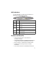
LED Indicators
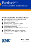
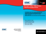
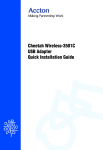
The SMC7004VWBR V.2 includes status LED indicators, as
described in the following figure and table.
4
Link/ACT
SMC7004VWBR V.2
Speed
LED
Status
Description
PWR
(Green)
On
The Wireless Barricade is receiving power.
WLAN
(Green)
On
The Wireless Barricade has established a valid wireless
connection.
WAN
(Green)
On
The WAN port has established a valid network
connection.
Link/ACT
(Green)
On
The indicated LAN port has established a valid network
connection.
Flashing The indicated LAN port is transmitting or receiving traffic.
Speed
(Amber)
Off
The indicated LAN port has established a valid 10 Mbps
network connection.
On
The indicated LAN port has established a valid 100 Mbps
network connection.
Features and Benefits
•
Internet connection to DSL or cable modem via a
10/100 Mbps WAN port
•
Local network connection via 10/100 Mbps Ethernet ports or
11 Mbps wireless interface (supporting up to 253 users)
•
•
802.11b compliant – interoperable with multiple vendors
•
Local network connection via 10/100 Mbps Ethernet ports
Provides seamless roaming within 802.11b WLAN
environment
3
About the Wireless Barricade Router
4
•
DHCP for dynamic IP configuration, and DNS for domain
name mapping
•
Stateful Packet Inspection (SPI) firewall with client privileges,
hacker prevention, and NAT
•
NAT also enables multi-user access with a single-user
account, and virtual server functionality (providing protected
access to Internet services such as Web, FTP, mail and
Telnet)
•
Virtual Private Network (VPN) support using PPTP, L2TP or
IPSec pass-through
•
User-definable application sensing tunnel supports
applications requiring multiple connections
•
Easy setup through a Web browser on any operating system
that supports TCP/IP
•
Compatible with all popular Internet applications
Installing the Wireless Barricade Router
INSTALLING THE WIRELESS
BARRICADE ROUTER
Before installing the Wireless Barricade™ Broadband Router,
verify that you have all the items listed under “Package
Contents.” If any of the items are missing or damaged, contact
your local SMC distributor. Also be sure that you have all the
necessary cabling before installing the Wireless Barricade. After
installing the Wireless Barricade, refer to the Web-based
configuration program in “Configuring the Wireless Barricade
Router” on page 27 for information on configuring the Wireless
Barricade.
Package Contents
After unpacking the Barricade™ Wireless Broadband Router,
check the contents of the box to be sure you have received the
following components:
•
Wireless Barricade Broadband Router
•
Power adapter
•
One CAT-5 Ethernet cable
•
Four rubber feet
•
Installation CD containing this User Guide and EZ 3-Click
Installation Wizard
•
Quick Installation Guide
5
Installing the Wireless Barricade Router
Immediately inform your dealer in the event of any incorrect,
missing or damaged parts. If possible, please retain the carton
and original packing materials in case there is a need to return
the product.
Hardware Description
The Wireless Barricade can be connected to the Internet using
its RJ-45 WAN port . It can be connected directly to your PC or to
a local area network using any of the Fast Ethernet LAN ports.
Access speed to the Internet depends on your service type.
Full-rate ADSL can provide up to 8 Mbps downstream and
640 Kbps upstream. G.lite (or splitterless) ADSL provides up to
1.5 Mbps downstream and 512 Kbps upstream. Cable modems
can provide up to 36 Mbps downstream and 2 Mbps upstream.
ISDN can provide up to 128 Kbps when using two bearer
channels. PSTN analog connections can now run up to 56 Kbps.
However, you should note that the actual rate provided by
specific service providers may vary dramatically from these
upper limits.
Although access speed to the Internet is determined by the
modem type connected to your Router, data passing between
devices connected to your local area network can run up to 100
Mbps over the Fast Ethernet ports.
The Wireless Barricade includes an LED display on the front
panel for system power and port indications that simplifies
installation and network troubleshooting. It also provides 4 RJ-45
LAN ports on the front panel, as well as one RJ-45 WAN port.
Full-duplex communications allow data to be sent and received
simultaneously, doubling the effective throughput.
6
Hardware Description
•
4 RJ-45 ports for connection to a 10BASE-T/100BASE-TX
Ethernet Local Area Network (LAN). These ports can
auto-negotiate the operating speed to 10/100 Mbps, the mode
to half/full duplex, and the pin signals to MDI/MDI-X
(i.e., allowing these ports to be connected to any network
device with straight-through cable). These ports can be
connected directly to a PC or to a server equipped with an
Ethernet network interface card, or to a networking device
such as an Ethernet hub or switch.
•
One RJ-45 port for connection to a DSL or cable modem
(WAN). This port also auto-negotiates operating speed to
10/100 Mbps, the mode to half/full duplex, and the pin signals
to MDI/MDI-X.
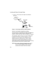
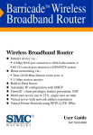
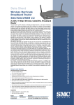
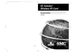
The following figure shows the components of the Wireless
Barricade:
4
Link/ACT
SMC7004VWBR V.2
Speed
Figure 1. Front and Rear Panels
7
Installing the Wireless Barricade Router
Item
Description
Reset
Button
Use this button to reset the power and restore the default factory
settings.
LAN
Ports
Fast Ethernet ports (RJ-45). Connect devices (such as a PC, hub
or switch) on your local area network to these ports.
WAN
Port
WAN port (RJ-45). Connect your cable modem, DSL modem, or an
Ethernet router to this port.
Power
Inlet
Connect the included power adapter to this inlet.
LEDs
Warning: Using the wrong type of power adapter may cause
damage.
Power, WAN and LAN port status indicators.
(See “LED Indicators” on page 3.)
System Requirements
You must have an ISP that meets the following minimum
requirements:
8
•
Internet access from your local telephone company or Internet
Service Provider (ISP) using a DSL modem or cable modem.
•
A PC using a fixed IP address or dynamic IP address
assigned via DHCP, as well as a gateway server address and
DNS server address from your service provider.
•
A computer equipped with a 10 Mbps, 100 Mbps, or
10/100 Mbps Fast Ethernet card, or a USB-to-Ethernet
converter.
•
TCP/IP network protocol installed on each PC that needs to
access the Internet.
•
A Java-enabled Web browser, such as Microsoft Internet
Explorer 5.0 or above, or Netscape Communicator 4.0 or
above installed on one PC at your site for configuring the
Wireless Barricade.
Connect the System
Connect the System
The Wireless Barricade can be positioned at any convenient
location in your office or home. No special wiring or cooling
requirements are needed. You should, however comply with the
following guidelines:
•
Keep the Wireless Barricade away from any heating devices.
•
Do not place the Wireless Barricade in a dusty or wet
environment.
You should also remember to turn off the power, remove the
power cord from the outlet, and keep your hands dry when you
install the Wireless Barricade.
Basic Installation Procedure
1. Connect the LAN: You can connect the Wireless Barricade to
your PC, or to a hub or switch. Run Ethernet cable from one
of the LAN ports on the front of the Wireless Barricade to your
computer’s network adapter or to another network device.
You may also connect the Wireless Barricade to your PC
(using a wireless client adapter) via radio signals. Position
both antennas on the back of the Wireless Barricade into the
desired positions. For more effective coverage, position one
antenna along the vertical axis and the other antenna along
the horizontal axis. (The antennas emit signals along the
toroidal plane – and thus provide more effective
coverage when positioned along alternate axes.)
2. Connect the WAN: Prepare an Ethernet cable for connecting
the Wireless Barricade to a cable/DSL modem or Ethernet
router. Prepare a serial cable for connecting the Wireless
Barricade to an ISDN TA or PSTN modem.
9
Installing the Wireless Barricade Router
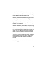
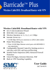
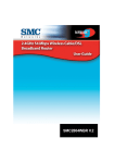
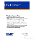
3. Power on: Connect the power adapter to the Wireless
Barricade.
Internet
Internet
Access
Device
Wireless Cable/DSL
Broadband Router
LAN
PWR
SMC700
WLAN
WAN
1
2
3
Link
Activity
4AWBR
Notebook with
Wireless PC Card
SOHO Office or Residence
Figure 2. Connecting the Wireless Barricade Router
Attach to Your Network Using Ethernet Cabling
The four LAN ports on the Wireless Barricade auto-negotiate the
connection speed to 10 Mbps Ethernet or 100 Mbps Fast
Ethernet, and the transmission mode to half duplex or full duplex.
Use twisted-pair cable to connect any of the four LAN ports on
the Wireless Barricade to an Ethernet adapter on your PC.
Otherwise, you can cascade any of the LAN ports on the
Wireless Barricade to an Ethernet hub or switch, and then
connect your PC or other network equipment to the hub or
switch. When inserting an RJ-45 plug, be sure the tab on the plug
clicks into position to ensure that it is properly seated.
Warning: Do not plug a phone jack connector into any RJ-45
port. This may damage the Wireless Barricade.
Instead, use only twisted-pair cables with RJ-45
connectors that conform with FCC standards.
10
Attach to Your Network Using Radio Signals
Install a wireless network adapter in each computer that will be
connected to the Internet or your local network via radio signals.
SMC currently offers several wireless network cards, including
the SMC2602W and SMC2632W Wireless cards.
Rotate both antennas on the back of the Wireless Barricade to
the desired position. For more effective coverage, position one
antenna along the vertical axis and the other along the horizontal
axis. Try to place the Wireless Barricade in a position that is
located in the center of your wireless network. Normally, the
higher you place the antenna, the better the performance. Ensure
that the Wireless Barricade’s location provides optimal reception
throughout your home or office.
Computers equipped with a wireless adapter can communicate
with each other as an independent wireless LAN by configuring
each computer to the same radio channel. However, the
Wireless Barricade can provide access to your wired/wireless
LAN or to the Internet for all wireless workstations. Each wireless
PC in this network infrastructure can talk to any computer in the
wireless group via a radio link, or access other computers or
network resources in the wired LAN infrastructure or over the
Internet via the Wireless Barricade.
The wireless infrastructure configuration not only extends the
accessibility of wireless PCs to the wired LAN, but also doubles
the effective wireless transmission range for wireless PCs by
retransmitting incoming radio signals through the Wireless
Barricade.
A wireless infrastructure can be used for access to a central
database, or for connection between mobile workers, as shown
in the following figure:
11
Installing the Wireless Barricade Router
Wired to Wireless
Network Extension
Internet
Internet
Access
Device
Notebook with Wireless
PC Card Adapter
LAN
PWR
SMC7004
WLAN
WAN
1
2
3
Link
Activity
AWBR
Wireless Cable/DSL
Broadband Router
Wired LAN
PC with Wireless
PCI Adapter
Figure 3. Making the WLAN Connections
Attach the Wireless Barricade Router to the Internet
If Internet services are provided through an xDSL or cable
modem, use unshielded or shielded twisted-pair Ethernet cable
(Category 3 or greater) with RJ-45 plugs to connect the
broadband modem directly to the WAN port on the Wireless
Barricade.
Note:
When connecting to the WAN port, use 100-ohm
Category 3, 4, or 5 shielded or unshielded twisted-pair
cable with RJ-45 connectors at both ends for all
connections.
Connecting the Power Adapter
Plug the power adapter into the power socket on the Wireless
Barricade, and the other end into a power outlet. Check the
indicator marked “PWR” on the front panel to be sure it is on. If
the power indicator does not light, refer to “Troubleshooting” on
page 67.
12
Configuring Client TCP/IP
CONFIGURING
CLIENT TCP/IP
If you have not previously installed the TCP/IP protocols on your
client PCs, refer to the following section. If you need information
on how to configure a TCP/IP address on a PC, refer to “Setting
Up TCP/IP” on page 15.
Installing TCP/IP
Windows 95/98/Me
1. Click Start/Settings/Control Panel.
2. Double-click the Network icon and select the Configuration
tab in the Network window.
3. Click the Add button.
4. Double-click Protocol.
13
Configuring Client TCP/IP
5. Select Microsoft in the manufacturers list. Select TCP/IP in
the Network Protocols list. Click the OK button to return to the
Network window.
6. The TCP/IP protocol will be listed in the Network window.
Click OK. The operating system may prompt you to restart
your system. Click Yes and the computer will shut down and
restart.
Windows 2000
1. Click the Start button and choose Settings, then click the
Network and Dial-up Connections icon.
2. Double-click the Local Area Connection icon, and click the
Properties button on the General tab.
3. Click the install... button.
14
Setting Up TCP/IP
4. Double-click Protocol.
5. Choose Internet Protocol (TCP/IP). Click the OK button to
return to the Network window.
6. The TCP/IP protocol will be listed in the Network window.
Click OK to complete the installation procedure.
Setting Up TCP/IP
To access the Internet through the Wireless Barricade, you must
configure the network settings of the computers on your LAN to
use the same IP subnet as the Wireless Barricade. The default
network settings for the Wireless Barricade are:
Gateway IP Address: 192.168.2.1
Subnet Mask: 255.255.255.0
15
Configuring Client TCP/IP
Note:
These settings may be changed to suit your network
requirements, but you must first configure at least one
computer as described in this chapter to access the
Wireless Barricade’s Web configuration interface.See
“Configuring the Wireless Barricade Router” on page
27 for information on configuring the Wireless
Barricade.)
If you have not previously configured TCP/IP for your computer,
refer to“Configuring Client TCP/IP” on page 13. The IP address
of the connected client PC should be 192.168.2.x (where x
means 2–254). You can set the IP address for client PCs either
by automatically obtaining an IP address from the Wireless
Barricade’s DHCP service or by manual configuration.
Configuring Your Computer in Windows 95/98/Me
You may find that the instructions here do not exactly match your
version of Windows. This is because these steps and
screenshots were created in Windows 98. Windows 95 and
Windows Millennium Edition are very similar, but not identical, to
Windows 98.
1. From the Windows desktop, click Start/Settings/Control
Panel.
2. In the Control Panel, locate and double click the Network icon.
16
Setting Up TCP/IP
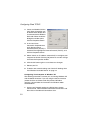
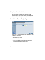
3. On the Network window
Configuration tab,
double-click the TCP/IP
entry for your network
card.
4. Click the IP Address tab.
5. Click the “Obtain an IP
address “option.
6. Next click on the Gateway
tab and verify the Gateway
field is blank. If there are
IP addresses listed in the Gateway section, highlight each
one and click Remove until the section is empty.
7. Click the OK button to close the TCP/IP Properties window.
17
Configuring Client TCP/IP
8. On the Network Properties Window, click the OK button to
save these new settings.
Note:
Windows may ask you for the original Windows
installation disk or additional files. Check for the files at
c:\windows\options\cabs, or insert your Windows
CD-ROM into your CDROM drive and check the correct
file location, e.g., D:\win98, D:\win9x. (if D is the letter
of your CD-ROM drive).
9. Windows may prompt you to restart the PC. If so, click the Yes
button. If Windows does not prompt you to restart your
computer, do so to insure your settings.
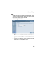
Obtain IP Settings from Your Wireless Barricade Router
Now that you have configured your computer to connect to your
Router, it needs to obtain new network settings. By releasing old
IP settings and renewing them with settings from the Wireless
Barricade, you will also verify that you have configured your
computer correctly.
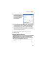
1. Click Start/Run.
2. Type WINIPCFG and click
OK.
3. From the drop-down menu,
select your network card.
Click Release and then
Renew. Verify that your IP
address is now
192.168.2.xxx, your Subnet
Mask is 255.255.255.0 and
your Default Gateway is
192.168. 2.1. These values confirm that the Wireless
18
Setting Up TCP/IP
Barricade is functioning. Click OK to close the IP
Configuration window.
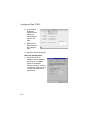
Configuring Your Computer in Windows NT 4.0
1. From the Windows desktop click Start/Settings/Control Panel.
2. Double-click the
Network icon.
3. Click on the
Protocols tab.
4. Double-click
TCP/IP Protocol.
5. Click on the IP Address tab.
19
Configuring Client TCP/IP
6. In the Adapter drop-down list, be sure your Ethernet adapter
is selected.
7. Click on “Obtain an IP address from a DHCP server”.
8. Click OK to close the window.
9. Windows may copy files and will then prompt you to restart
your system. Click Yes and your computer will shut down and
restart.
Obtain IP Settings From Your Wireless Barricade Router
Now that you have configured your computer to connect to the
Wireless Barricade, it needs to obtain new network settings. By
releasing old IP settings and renewing them with settings from
the Wireless Barricade, you will also verify that you have
configured your computer correctly.
1. On the Windows desktop, click Start/Programs/Command
Prompt.
2. In the Command Prompt window, type IPCONFIG /RELEASE
and press the <ENTER> key.
20
Setting Up TCP/IP
3. Type IPCONFIG /RENEW and press the <ENTER> key. Verify
that your IP Address is now 192.168.2.xxx, your Subnet Mask
is 255.255.255.0 and your Default Gateway is 192.168.2.1.
These values confirm that the Wireless Barricade is
functioning.
4. Type EXIT and press <ENTER> to close the Command
Prompt window.
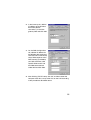
Configuring Your Computer in Windows 2000
1. Access your Network settings by clicking Start, then choose
Settings and then select Control Panel.
2. In the Control Panel, locate and double-click the Network and
Dial-up Connections icon.
21
Configuring Client TCP/IP
3. Locate and double-click the
Local Area Connection icon
for the Ethernet adapter that
is connected to the Wireless
Barricade. When the Status
dialog box window opens,
click the Properties button.
4. In the Local Area
Connection Properties box,
verify the box next to
Internet Protocol (TCP/IP) is
checked. Then highlight the Internet Protocol (TCP/IP), and
click the Properties button.
5. Select “Obtain an IP address automatically” to configure your
computer for DHCP. Click the [OK] button to save this change
and close the Properties window.
6. Click the OK button again to save these new changes.
7. Reboot your PC.
8. To obtain new network settings see “Obtain IP Settings from
Your Wireless Barricade Router” on page 18.
Configuring Your Computer in Windows XP
The following instructions assume you are running Windows XP
with the default interface. If you are using the Classic interface
(where the icons and menus look like previous Windows
versions), please follow the instructions for Windows 2000
outlined above.
1. Access your Network settings by clicking Start, choose
Control Panel, select Network and Internet Connections and
then click on the Network Connections icon.
22
Setting Up TCP/IP
2. Locate and double-click the
Local Area Connection icon
for the Ethernet adapter that
is connected to the Wireless
Barricade. Next, click the
Properties button.
3. the Local Area Connection Properties box, verify the box next
to Internet Protocol (TCP/IP) is checked. Then highlight the
Internet Protocol (TCP/IP), and click the Properties button.
4. Select “Obtain an IP address automatically” to configure your
computer for DHCP. Click the OK button to save this change
and close the Properties window.
5. Click the OK button again to save these new changes.
6. Reboot your PC.
Configuring a Macintosh Computer
You may find that the instructions here do not exactly match your
screen. This is because these steps and screenshots were
created using Mac OS 8.5. Mac OS 7.x and above are all very
similar, but may not be identical to Mac OS 8.5.
1. Pull down the Apple Menu. Click Control Panel and select
TCP/IP.
23
Configuring Client TCP/IP
2. In the TCP/IP
dialog box,
make sure that
Ethernet is
selected in the
Connect Via:
field.
3. Select Using
DHCP Server in
the Configure
field.
4. Close the TCP/IP dialog box.
Manual IP Configuration
1. Check Specify an IP
address on the IP Address
tab. Enter an IP address
based on the default
network 192.168.2.x (where
x is between 2 and 254), and
use 255.255.255.0 for the
subnet mask.
24
2. In the Gateway tab, add the
IP address of the Wireless
Barricade (default:
192.168.2.1) in the New
gateway field and click Add.
3. On the DNS Configuration
tab, add the IP address for
the Wireless Barricade and
click Add. This automatically
relays DNS requests to the
DNS server(s) provided by
your ISP. Otherwise, add
specific DNS servers into
the DNS Server Search
Order field and click Add.
4. After finishing TCP/IP setup, click OK, and then reboot the
computer. After that, set up other PCs on the LAN according
to the procedures described above.
25
Configuring Client TCP/IP
Verifying Your TCP/IP Connection
After installing the TCP/IP communication protocols and
configuring an IP address in the same network as the Wireless
Barricade, use the Ping command to check if your computer has
successfully connected to the Wireless Barricade. The following
example shows how the Ping procedure can be executed in an
MS-DOS window. First, execute the Ping command:
ping 192.168.2.1
If a message similar to the following appears:
Pinging 192.168.2.1 with 32 bytes of data:
Reply from 192.168.2.1: bytes=32 time=2ms TTL=64
a communication link between your computer and the Wireless
Barricade has been successfully established.
If you get the following message,
Pinging 192.168.2.1 with 32 bytes of data:
Request timed out.
there may be something wrong in your installation procedure.
Check the following items in sequence:
1. Is the Ethernet cable correctly connected between the
Wireless Barricade and the computer?
The LAN LED on the Wireless Barricade and the Link LED of
the network card on your computer must be on.
2. Is TCP/IP properly configured on your computer?
If the IP address of the Wireless Barricade is 192.168.2.1, the
IP address of your PC must be from 192.168.2.2 192.168.2.254 and the default gateway must be 192.168.2.1.
If you can successfully Ping the Wireless Barricade you are
now ready to connect to the Internet!
26
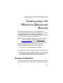
Configuring the Wireless Barricade Router
CONFIGURING THE
WIRELESS BARRICADE
ROUTER
The Wireless Barricade Router can be configured by any
Java-supported browser including Internet Explorer 5.0 or above,
or Netscape Navigator 4.0 or above. Using the Web
management interface, you can configure the Wireless Barricade
and view statistics to monitor network activity.
Note:
Before you attempt to configure your router, if you have
access to the Internet please visit www.smc.com or
www.smc-europe.com and download the latest firmware update to insure your router is running the latest
Before you attempt to log into the Wireless Barricade’s
Web-based Administration, please verify the following.
1. Your browser is configured properly (see below).
2. Disable any firewall or security software that may be running.
3. Confirm that you have a good link LED where your computer
is plugged into the Wireless Barricade. If you don’t have a link
light – then try another cable until you get a good link.
Browser Configuration
Confirm your browser is configured for a direct connection to the
Internet using the Ethernet cable that is installed in the computer.
27
Configuring the Wireless Barricade Router
This is configured through the options/preference section of your
browser.
Disable Proxy Connection
You will also need to verify that the HTTP Proxy feature of your
web browser is disabled. This is so that your web browser will be
able to view the Wireless Barricade configuration pages. The
following steps are for Internet Explorer and for Netscape.
Determine which browser you use and follow the appropriate
steps.
Internet Explorer (5 or above)
1. Open Internet Explorer. Click Tools, and then select Internet
Options.
2. In the Internet Options window, click the Connections tab.
3. Click the LAN Settings button.
4. Clear all the check boxes and click OK to save these LAN
settings changes.
5. Click OK again to close the Internet Options window.
Internet Explorer (For Macintosh)
1. Open Internet Explorer. Click Edit/Preferences.
2. In the Internet Explorer Preferences window, under Network,
select Proxies.
3. Uncheck all checkboxes and click OK.
28
Netscape (4 or above)
Netscape (4 or above)
1. Open Netscape. Click Edit, and then select Preferences.
2. In the Preferences window, under Category, double-click
Advanced, then select the Proxies option.
3. Check “Direct connection to the Internet.”
4. Click the OK button to save the changes.
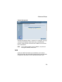
To access the Wireless Barricade’s
management interface, enter the
Wireless Barricade IP address in your
Web browser http://192.168.2.1. Then
click LOGIN. (By default, there is no
password.)
The home page displays the Setup Wizard and Advanced Setup
options.
29
Configuring the Wireless Barricade Router
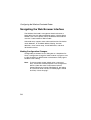
Navigating the Web Browser Interface
The Wireless Barricade’s management interface features a
Setup Wizard and an Advanced Setup section. Use the Setup
Wizard if you want to quickly set up the Wireless Barricade for
use with a cable modem or DSL modem.
Advanced setup supports more advanced functions like hacker
attack detection, IP and MAC address filtering, intrusion
detection, virtual server setup, virtual DMZ hosts, and other
advanced functions.
Making Configuration Changes
Configurable parameters have a dialog box or a drop-down list.
Once a configuration change has been made on a page, be sure
to click the APPLY or NEXT button at the bottom of the page to
enable the new setting.
Note:
30
To ensure proper screen refresh after a command
entry, ensure that Internet Explorer 5.0 is configured as
follows: Under the menu Tools/Internet Options/
General/Temporary Internet Files/Settings, the setting
for “Check for newer versions of stored pages” should
be “Every visit to the page.”
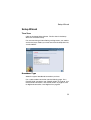
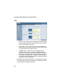
Setup Wizard
Setup Wizard
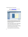
Time Zone
Click on the Setup Wizard picture. The first item in the Setup
Wizard is Time Zone setup.
For accurate timing of client filtering and log events, you need to
set the time zone. Select your time zone from the drop-down list,
and click NEXT.
.
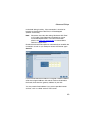
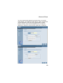
Broadband Type
Select the type of broadband connection you have.
For a cable modem connection see the following page. For a
Fixed-IP xDSL connection see “Fixed-IP xDSL” on page 33, for a
PPPoE xDSL connection, see “PPPoE xDSL” on page 33, and
for BigPond connection, see “BigPond” on page 35.
31
Configuring the Wireless Barricade Router
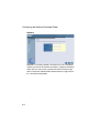
Cable Modem
Your ISP may have given you a host name. If so, enter it into the
field.
Click Finish to complete the setup. The Status page will open to
allow you to view the connection status, as well as other
information. See “Status” on page 66 for details.
32
Setup Wizard
Fixed-IP xDSL
Some xDSL Internet Service Providers may assign a fixed
(static) IP address. If you have been provided with this
information, choose this option and enter the assigned IP
address, gateway IP address, DNS IP addresses, and subnet
mask. Click FINISH to complete the setup.
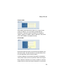
PPPoE xDSL
Enter the PPPoE User Name and Password assigned by your
Service Provider. The Service Name is normally optional, but
may be required by some service providers.
Leave the Maximum Transmission Unit (MTU) at the default
value (1454) unless you have a particular reason to change it.
Enter a Maximum Idle Time (in minutes) to define a maximum
period of time for which the Internet connection is maintained
33
Configuring the Wireless Barricade Router
during inactivity. If the connection is inactive for longer than the
Maximum Idle Time, it will be dropped. (Default: 10)
Enable the Auto-reconnect option to automatically re-establish
the connection as soon as you attempt to access the Internet
again. Click FINISH to complete the setup.
PPTP (Point-to-Point Tunneling Protocol)
Point-to-Point Tunneling Protocol is a common connection
method used for xDSL connections in Europe. It can be used to
join different physical networks using the Internet as an
intermediary.
If you have been provided with the information as shown on the
screen, enter the assigned IP address, subnet mask, default
gateway IP address, user ID and password, and PPTP Gateway.
The MTU (Maximum Transmission Unit) governs the maximum
size of the data packets. Leave this on the default value (1460)
unless you have a particular reason to change it.
Enter a Maximum Idle Time (in minutes) to define a maximum
period of time for which the Internet connection is maintained
during inactivity. If the connection is inactive for longer than the
Maximum Idle Time, it will be dropped. (Default: 0)
34
Setup Wizard
Note:
Please be aware that the setting "Maximum Idle Time"
to "0" and/or "Auto-Reconnect" enabled can cause
increased telephone bills. For further information
please visit www.smc-europe.com or contact SMC's
technical support team.
Enable the Auto-reconnect option to automatically re-establish
the connection as soon as you attempt to access the Internet
again.
Click FINISH to complete the setup. (Refer to “Point-to-Point
Tunneling Protocol (PPTP)” on page 42 for details.)
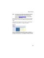
BigPond
If you use the BigPond Internet Service which is available in
Australia, enter the the user name, password and service name
for BigPond authentication. Click FINISH to complete the setup.
35
Configuring the Wireless Barricade Router
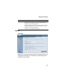
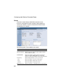
Advanced Setup
Use the Web management interface to define system
parameters, manage and control the Wireless Barricade and its
ports, or monitor network conditions. The following table outlines
the selections available from this program.
Menu
Description
System
Sets the local time zone, the password for administrator access,
and the IP address of a PC that will be allowed to manage the
Wireless Barricade remotely.
WAN
Specifies the Internet connection type:
• Dynamic IP host configuration and the physical MAC address
of each media interface
• PPPoE configuration
• PPTP
• Static IP and ISP gateway address
• BigPond (Internet service available in Australia)
• Specifies DNS servers to use for domain name resolution.
36
LAN
Sets the TCP/IP configuration of the Wireless Barricade’s LAN
interface and all DHCP clients.
Wireless
Configures the radio frequency, SSID, and encryption for
wireless communications.
NAT
Shares a single ISP account with multiple users, sets up virtual
servers.
Firewall
Configures a variety of security and specialized functions,
including: Access Control, Hacker Prevention, and DMZ.
DDNS
Dynamic DNS provides users on the Internet with a method to
tie their domain name(s) to computers or servers.
UPnP
With Universal Plug and Play, a device can automatically
dynamically join a network, obtain an IP address, communicate
its capabilities, and learn about the presence and capabilities of
other devices. Devices can then directly communicate with each
other. This further enables peer to peer networking.
Tools
Contains options to backup & restore the current configuration,
restore all configuration settings to the factory defaults, update
system firmware, or reset the system.
Advanced Setup
Menu
Description
Status
Provides WAN connection type and status, firmware and
hardware version numbers, system IP settings, as well as
DHCP, NAT, and Firewall information.
Displays the number of attached clients, the firmware versions,
the physical MAC address for each media interface, and the
hardware version and serial number.
Shows the security and DHCP client log.
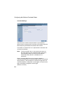
System
Time Zone
Select your time zone and time server from the drop-down list for
the Wireless Barricade. This information is used for log entries
and client access control.
37
Configuring the Wireless Barricade Router
Password Settings
Use this menu to restrict access based on a password. By
default, there is no password. For security you should assign one
before exposing the Wireless Barricade to the Internet.
Passwords can contain from 3–12 alphanumeric characters and
are not case sensitive.
Note:
If your password is lost, or you cannot gain access to
the user interface, press the Reset button on the front
panel (holding it down for at least five seconds) to
restore the factory defaults. (The default is no
password.)
Enter a maximum Idle Time Out (in minutes) to define a
maximum period of time for which the login session is maintained
during inactivity. If the connection is inactive for longer than the
maximum idle time, it will perform system logout, and you have to
login to the Web management system again.
(Default: 9 minutes)
38
Advanced Setup
Remote Management
Remote Management allows a remote PC to configure, manage,
and monitor the Wireless Barricade using a standard Web
browser. Check Enable and enter the IP address of the remote
host. Click APPLY.
Note:
If you specify 0.0.0.0 as this IP address, any host can
manage the Wireless Barricade.
WAN
Specify the WAN connection type provided by your Internet
Service Provider, then click More Configuration to enter detailed
configuration parameters for the selected connection type.
39
Configuring the Wireless Barricade Router
Dynamic IP
The Host Name is optional, but may be required by some ISPs.
The default MAC address is set to the WAN’s physical interface
on the Wireless Barricade. Use this address when registering for
Internet service, and do not change it unless required by your
ISP. If your ISP used the MAC address of an Ethernet card as an
identifier when first setting up your broadband account, only
connect the PC with the registered MAC address to the Wireless
Barricade and click the Clone MAC Address button. This will
replace the current Router MAC address with the already
registered Ethernet card MAC address.
If you are unsure of which PC was originally set up by the
broadband technician, call your ISP and request that they
register a new MAC address for your account. Register the
default MAC address of the Wireless Barricade.
40
Advanced Setup
Point-to-Point Over Ethernet (PPPoE)
Enter the PPPoE User Name and Password assigned by your
Service Provider. The Service Name is normally optional, but
may be required by some service providers.
The MTU (Maximum Transmission Unit) governs the maximum
size of the data packets. Leave this on the default value (1454)
unless you have a particular reason to change it.
Enter a Maximum Idle Time (in minutes) to define a maximum
period of time for which the Internet connection is maintained
during inactivity. If the connection is inactive for longer than the
Maximum Idle Time, it will be dropped. (Default: 10 minutes)
Enable the Auto-reconnect option to automatically re-establish
the connection as soon as you attempt to access the Internet
again.
Note:
Please be aware that the setting "Maximum Idle Time"
to "0" and/or "Auto-Reconnect" enabled can cause
increased telephone bills. For further information
41
Configuring the Wireless Barricade Router
please visit www.smc-europe.com or contact SMC's
technical support team.
Point-to-Point Tunneling Protocol (PPTP)
Point-to-Point Tunneling Protocol (PPTP) can be used to join
different physical networks using the Internet as an intermediary.
Using the above screen allows client PCs to establish a normal
PPTP session and provides hassle-free configuration of the
PPTP client on each client PC.
Enter the assigned IP address, subnet mask and default gateway
IP address (usually supplied by your ISP), and then the PPTP
User ID, Password and PPPTP Gateway IP address.
The MTU (Maximum Transmission Unit) governs the maximum
size of the data packets. Leave this on the default value (1460)
unless you have a particular reason to change it.
Enter a maximum Idle Time Out (in minutes) to define a
maxi-mum period of time for which the PPTP connection is
42
Advanced Setup
maintained during inactivity. If the connection is inactive for
longer than the Maximum Idle Time, it will be dropped.
(Default: 10 minutes)
Note:
Please be aware that the setting "Maximum Idle Time"
to "0" and/or "Auto-Reconnect" enabled can cause
increased telephone bills. For further information
please visit www.smc-europe.com or contact SMC's
technical support team.
Enable the Auto-reconnect option to automatically re-establish the
connection as soon as you attempt to access the Internet again.
Static IP
If your Internet Service Provider has assigned a fixed IP address,
enter the assigned address and subnet mask for the Wireless
Barricade, then enter the gateway address of your ISP.
You may need a fixed address if you want to provide Internet
services, such as a Web server or FTP server.
43
Configuring the Wireless Barricade Router
BigPond
BigPond is a service provider in Australia that uses a heartbeat
system to maintain the Internet connection. Configure the built-in
client with your user name, password and service name to get
online. Leave the Authentication Service Name as “login-server”
for a universal configuration.
44
Advanced Setup
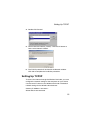
DNS
Domain Name Servers map numerical IP addresses to the
equivalent domain name (e.g., www.smc.com). Your ISP should
provide the IP address of one or more domain name servers.
Enter those addresses in this screen.
45
Configuring the Wireless Barricade Router
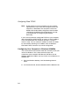
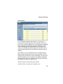
LAN
•
LAN IP – Use the LAN menu to configure the LAN IP address
for the Wireless Barricade and to enable the DHCP server for
dynamic client address allocation.
•
Lease Time - Set a period for the lease time if required. For
home networks this may be set to Forever, which means there
is no time limit on the IP address lease.
•
IP Address Pool – A dynamic IP start address may be
specified by the user, e.g. 192.168.2.100 (default value).
Once this start IP address has been assigned, IP addresses
running from 192.168.2.100 to 192.168.2.199 will be part of
the dynamic IP address pool. IP addresses from 192.168.2.2
to 192.168.2.99, and 192.168.2.200 to 192.168.2.254 will be
available as static IP addresses.
Remember not to include the address of the Wireless Barricade
in the client address pool. Also remember to configure your client
PCs for dynamic IP address allocation.
46
Advanced Setup
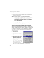
Wireless
To configure the Wireless Barricade as a wireless access point
for wireless clients (either stationary or roaming), all you need to
do is define the radio channel, the Service Set identifier (SSID),
and encryption options.
Channel and SSID
You must specify a common radio channel and SSID (Service
Set ID) to be used by the Wireless Barricade and all of your
wireless clients. Be sure you configure all of your clients to the
same values.
ESSID: The Service Set ID. This should be set to the same value
as other wireless devices in your network. (Default: SMC.)
Note:
The SSID is case sensitive and can consist of up to 32
alphanumeric characters.
47
Configuring the Wireless Barricade Router
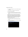
Transmission Rate: Set the data rate transmitted
from the Wireless Barricade. The lower the data
rate, the longer the transmission distance.
(Default: Fully Automatic.)
Basic Rate: The highest rate specified is the rate the
Wireless Barricade will use when transmitting
broadcast/multicast and management frames.
Available options are: 1, 2, 5.5, and 11Mbps.
(Default: 2Mbps.)
Channel: The radio channel through which the Wireless
Barricade communicates with PCs in its BSS. (Default: 6)
Note:
The available channel settings are limited by local
regulations.
Broadcast SSID: Broadcasting the SSID on the wireless
network for easy connection with client PCs.
(Default: Enable)
Encryption
If you are transmitting sensitive
data across wireless channels,
you should enable Wired
Equivalent Privacy (WEP)
encryption. Encryption requires you to use the same set of
encryption/decryption keys for the Wireless Barricade and all of
your wireless clients. You can choose between standard 64-bit or
the more robust 128-bit encryption.
48
Advanced Setup
You may automatically generate encryption keys or manually
enter the keys. For automatic 64-bit security, enter a passphrase
and click Generate. Four keys will be generated (as shown
below). Choose a key from the drop-down list or accept the
default key. Automatic 128-bit security generates a single key.
49
Configuring the Wireless Barricade Router
If you use encryption, configure the same keys used for the
Wireless Barricade on each of your wireless clients. Note that
Wired Equivalent Privacy (WEP) protects data transmitted
between wireless nodes, but does not protect any transmissions
over your wired network or over the Internet.
Network Address Translation (NAT)
From this section you can configure the Address Mapping, Virtual
Server, and Special Application features that provide control over
the port openings in the Wireless Barricade’s firewall. This
section can be used to support several Internet based
applications such as VPN
Address Mapping
Allows one or more public IP addresses to be shared by multiple
internal users. Enter the Public IP address you wish to share into
the Global IP field. Enter a range of internal IPs that will share the
global IP.
50
Advanced Setup
Virtual Server
If you configure the Wireless Barricade as a virtual server,
remote users accessing services such as Web or FTP at your
local site via public IP addresses can be automatically redirected
to local servers configured with private IP addresses. In other
words, depending on the requested service (TCP/UDP port
number), the Wireless Barricade redirects the external service
request to the appropriate server (located at another internal IP
address).
For example, if you set Type/Public Port to TCP/80 (HTTP or
Web) and the Private IP/Port to 192.168.2.2/80, then all HTTP
requests from outside users will be transferred to 192.168.2.2 on
port 80. Therefore, by just entering the IP Address provided by
the ISP, Internet users can access the service they need at the
local address to which you redirect them.
The more common TCP service ports include:
HTTP: 80, FTP: 21, Telnet: 23, and POP3: 110.
51
Configuring the Wireless Barricade Router
Special Applications
Some applications, such as Internet gaming, videoconferencing,
Internet telephony and others, require multiple connections.
These applications cannot work with Network Address
Translation (NAT) enabled. If you need to run applications that
require multiple connections, use the following screen to specify
the additional public ports to be opened for each application.
Specify the public port number normally associated with an
application in the Trigger Port field. Set the protocol type to TCP
or UDP, then enter the ports that the application requires. The
ports may be in the format 7, 11, 57, or in a range, e.g., 72-96, or
a combination of both, e.g., 7, 11, 57, 72-96.
For a full list of ports and the services that run on them, see
www.iana.org/assignments/port-numbers.
52
Advanced Setup
Firewall
The Wireless Barricade firewall can provide access control of
connected client PCs, block common hacker attacks, including IP
Spoofing, Land Attack, Ping of Death, IP with zero length, Smurf
Attack, UDP port loopback, Snork Attack, TCP null scan, and
TCP SYN flooding. The firewall does not significantly affect
system performance, so we advise leaving it enabled to protect
your network users.
Access Control
Using this option allows you to specify different privileges based
on IP address for the client PCs.
53
Configuring the Wireless Barricade Router
Note:
54
Click on Add PC and define the appropriate settings for
client PC services (as shown in the following screen).
Advanced Setup
MAC Filtering Table
The MAC Filtering feature of the Wireless Barricade allows you to
control access to your network to up to 32 clients based on the
MAC (Media Access Control) Address of the client machine. This
ID is unique to each network adapter. If the MAC address is
listed in the table, that client machine will have access to the
network.
55
Configuring the Wireless Barricade Router
URL Blocking
To configure the URL Blocking feature, use the table below to
specify the websites (www.somesite.com) and/or keywords you
want to filter on your network.
To complete this configuration, you will need to create or modify
an access rule in “Access Control” on page 53. To modify an
existing rule, click the Edit option next to the rule you want to
modify. To create a new rule, click on the Add PC option.
From the Access Control Add PC section check the option for
WWW with URL Blocking in the Client PC Service table to filter
out the websites and keywords specified below.
Use the above screen to block access to Web sites or to Web
URLs containing the keyword specified in the table.
56
Advanced Setup
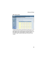
Schedule Rule
The Schedule Rule feature allows you to configure specific rules
based on Time and Date. These rules can then be used to
configure more specific Access Control.
Enables Schedule-based Internet access control.
1. Click Add Schedule Rule.
2. Define the settings for the schedule rule (as shown on the
following screen).
3. Click OK and then click the APPLY button to save your
settings.
57
Configuring the Wireless Barricade Router
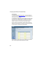
Use this section to create your network schedule rules.
The times you set below are the times periods that you want the
Access Control Rule to be active. For example, if you want to
block Internet access (block WWW) from 9AM to 9PM during the
week. Simply configure 9:00 AM as “Start Time” and 9:00 PM as
“End Time” for each weekday - during that time period the user
will be unable to access the internet.
Once the schedule rule is setup, you will need to configure or edit
an Access Control rule, and select your Schedule Rule that you
want to apply to that Access Control rule. You can set the
schedule rule at the bottom of the Access Control Configuration
page in the “Scheduling Rule” drop-down option.
58
Advanced Setup
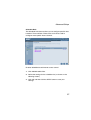
Intrusion Detection
Firewall Configuration
•
SPI (Stateful Packet Inspection) and Anti-DoS firewall
protection (Default: Enabled) – the Wireless Barricade’s
Intrusion Detection feature limits access for incoming traffic at
the WAN port. When the SPI feature is turned on, all incoming
packets will be blocked.
•
Discard Ping from WAN (Default: Enabled)
– Prevents a PING on the Wireless Barricade’s WAN port from
being routed to the network.
E-Mail Alert Configuration
•
When hackers attempt to enter your network, we can alert
you by e-mail – Enter your E-mail address. Specify your
SMTP and POP3 servers, user name, and password.
59
Configuring the Wireless Barricade Router
DMZ (Demilitarized Zone)
If you have a client PC that cannot run an Internet application
properly from behind the firewall, then you can open the client up
to unrestricted two-way Internet access. Enter the IP address of
a DMZ host to this screen. Adding a client to the DMZ may
expose your local network to a variety of security risks, so only
use this option as a last resort.
60
Advanced Setup
DDNS (Dynamic DNS) Settings
Domain Name is a series of alphanumeric strings separated by
periods, that is the address of a network connection and that
identifies the owner of the address.
Dynamic DNS provides users on the Internet with a method to tie
their domain name(s) to computers or servers. DDNS allows your
domain name to follow your IP address automatically by having
your DNS records changed when your IP address changes.
The Server Configuration section automatically opens the port
options checked in the Virtual Server section. Simply enter in the
IP Address of your server, such as a web server, and then click
on the port option HTTP Port 80 so users can access your server
from the WAN connection (Internet).
61
Configuring the Wireless Barricade Router
This DNS feature is powered by TZO.com. With a DDNS
connection you can host your own web site, email server, FTP
site, and more at your own location even if you have a dynamic
IP address. (Default: Disable)
UPnP (Universal Plug and Play) Setting
Enable UPnP by checking ON in the screen above. UPnP allows
the device to automatically:
62
•
dynamically join a network
•
obtain an IP address
•
convey its capabilities and learn about the presence and
capabilities of other devices.(Default: OFF)
Advanced Setup
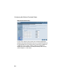
Tools
Use the Tools menu to backup the current configuration, restore
a previously saved configuration, restore factory settings, update
firmware, and reset the Wireless Barricade.
Tools - Configuration Tools
•
Backup – saves the Wireless Barricade’s configuration to a
file.
•
Restore – restores settings from a saved backup configuration
file.
•
Restore to factory defaults – restores the Wireless Barricade
settings back to the factory default original.
63
Configuring the Wireless Barricade Router
Tools - Firmware Upgrade
Use this screen to update the firmware or user interface to the
latest versions. Download the upgrade file from the SMC Web
site (www.smc.com) and save it to your hard drive. In the
Upgrade Target field, choose Firmware. Then click Browse to
look for the previously downloaded file. Click APPLY. Check the
Status page Information section to confirm that the upgrade
process was successful.
64
Tools - Reset
Click APPLY to reset the Wireless Barricade. The reset will be
complete when the power LED stops blinking.
Note:
If you use the Reset button on the front panel, the
Wireless Barricade performs a power reset. If the
button is held depressed for over five seconds, all the
LEDs will illuminate and the factory settings will be
restored.
65
Configuring the Wireless Barricade Router
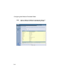
Status
The Status screen displays WAN/LAN connection status,
firmware, and hardware version numbers, illegal attempts to
access your network, as well as information on DHCP clients
connected to your network.
The following items are included on this screen:
Section
Description
INTERNET
Displays WAN connection type and status.
Wireless Barricade
Displays system IP settings, as well as DHCP, Firewall,
UPnP and Wireless status.
INFORMATION
Displays the number of attached clients, the firmware
versions, the physical MAC address for each media
interface, as well as the hardware version and serial number.
Security Log
Displays illegal attempts to access your network.
Save
Click on this button to save the security log file.
Clear
Click on this button to delete the access log.
Refresh
DHCP Client Log
66
Click on this button to refresh the screen.
Displays information on all DHCP clients on your network.
Troubleshooting
TROUBLESHOOTING
The information outlined in this section describes some useful
steps for getting your computer and the Wireless Barricade
Router online.
A. Verify your connection to the Wireless Barricade
If you are unable to access the Wireless Barricade’s web-based
administration pages then you may not be properly connected or
configured. The screen shots in this section were taken on a
Windows 2000 machine, but the same steps will apply to
Windows 95/98/Me/XP.
To determine your TCP/IP configuration status please follow the
steps below:
1. Click Start then choose Run.
2. Type cmd or command to open a DOS prompt.
3. In the DOS window, type ipconfig and verify the information
that is displayed.
4. If your computer is setup for DHCP, then your TCP/IP
configuration should be similar to the information displayed:
•
IP Address: 192.168.2.X (x is number between 100 and 199)
•
Subnet: 255.255.255.0
•
Gateway: 192.168.2.1
67
Troubleshooting
If you have any other IP address information listed see below.
If you have an IP address that starts with 169.254.XXX.XXX then
see the next section.
If you have another IP address configured, then see section C.
B. I am getting an IP Address that starts with
169.254.XXX.XXX
If you are getting this IP Address, then you need to check that
you are properly connected to the Wireless Barricade.
Confirm that you have a good link light on the Wireless Barricade
for the port this computer is connected to. If not, please try
another cable.
If you have a good link light, please open up a DOS window as
described in the previous section and type ipconfig/renew.
If you are still unable to get an IP Address from the Wireless
Barricade, reinstall your network adapter. Please refer to your
adapter manual for information on how to do this.
68
C. I have another IP Address displayed
If you have another IP address listed then the PC may not be
configured for a DHCP connection. Please refer to “Configuring
Client TCP/IP” on page 13 for information.
Once you have confirmed your computer is configured for DHCP,
then please follow the steps below.
1. Open a DOS window as described above.
2. Type ipconfig/release.
3. Then type ipconfig/renew.
69
Troubleshooting
D. The 10/100 LED does not light after a connection is made.
1. Check that the host computer and hub are both powered on.
2. Be sure the network cable is connected to both devices.
3. Verify that Category 5 cable is used if you are operating at
100 Mbps, and that the length of any cable does not exceed
100 m (328 ft).
4. Check the network card connections.
5. The 10BASE-T/100BASE-TX hub/switch port, network card,
or cable may be defective.
70
Specifications
SPECIFICATIONS
Below is an outline of the Technical Specifications for the
SMC7004VWBR V.2
Standards
IEEE 802.3 10BASE-T Ethernet
IEEE 802.3u 100BASE-TX Fast Ethernet
IEEE 802.11b
LAN Interface
4 - RJ-45 10/100 Mbps Auto MDI/MDI-X ports
WAN Interface
1- RJ-45 10/100 Mbps Auto MDI/MDI-X port
Management
Web management
Advanced Features
Dynamic IP Address Configuration – DHCP, DNS
Firewall – Client privileges, hacker prevention and logging
Virtual Private Network – PPTP, L2TP, IPSec pass-through
Indicator Panel
Power, WLAN, WAN (Link, Activity), LAN (Link/Activity,
10/100 Mbps)LAN: Link/Activity, 10/100 (Mbps)
Temperature
Operating: 0 to 40 °C (32 to 104 °F)
Storage: -20 to 70 °C (-4 to 158 °F)
Dimensions
130 x 85 x 32 mm (5.12 x 3.35 x 1.26 in.)
Weight
370 g (13.05 oz)
71
Specifications
Input Power
9 V (1 A)
Internet Standards
ARP (RFC 826), IP (RFC 791), ICMP (RFC 792), UDP (RFC
768), TCP (RFC 793), Telnet (RFC 854-859), MD5 (RFC 1321),
BOOTP Extension (RFC 1497), PPP LCP Extension (RFC 1570),
PPPoE (RFC 2516), NAT (RFC 1631), PPP (RFC 1661), HTML
(RFC 1866), HTTP (RFC 1945), CHAP (RFC 1944), DHCP (RFC
2131), PPTP (RFC 2637)
Temperature
Operating (0 to 40 °C), 32 to 104 °F
Storage (- 40 to 70 °C), - 40 to 158 °F
Humidity
5% to 95% (noncondensing)
Compliances
CE Mark
Emissions
FCC Class B
VCCI Class B
Industry Canada Class B
EN55022 (CISPR 22) Class B
C-Tick - AS/NZS 3548 (1995) Class B
Immunity
EN 61000-3-2/3
EN 61000-4-2/3/4/5/6/8/11
Safety
UL 1950
EN60950 (TÜV)
CSA 22.2 No. 950
72
COMPLIANCES
FCC - Class B
This equipment has been tested and found to comply with the limits for a Class B
digital device, pursuant to Part 15 of the FCC Rules. These limits are designed to
provide reasonable protection against harmful interference in a residential
installation. This equipment generates, uses and can radiate radio frequency
energy and, if not installed and used in accordance with instructions, may cause
harmful interference to radio communications. However, there is no guarantee that
the interference will not occur in a particular installation. If this equipment does
cause harmful interference to radio or television reception, which can be
determined by turning the equipment off and on, the user is encouraged to try to
correct the interference by one or more of the following measures:
• Reorient the receiving antenna
• Increase the separation between the equipment and receiver
• Connect the equipment into an outlet on a circuit different from that to
which the receiver is connected
• Consult the dealer or an experienced radio/TV technician for help
FCC Caution: To assure continued compliance, (example - use only shielded
interface cables when connecting to computer or peripheral devices) any changes
or modifications not expressly approved by the party responsible for compliance
could void the user’s authority to operate this equipment.
This device complies with Part 15 of the FCC Rules. Operation is subject to the
following two conditions: (1) This device may not cause harmful interference, and
(2) this device must accept any interference received, including interference that
may cause undesired operation.
IMPORTANT NOTE:
FCC Radiation Exposure Statement
This equipment complies with FCC radiation exposure limits set forth for an
uncontrolled environment. This transmitter must not be co-located or operating in
conjunction with any other antenna or transmitter.
i
Compliances
Industry Canada - Class B
This digital apparatus does not exceed the Class B limits for radio noise emissions
from digital apparatus as set out in the interference-causing equipment standard
entitled “Digital Apparatus” ICES-003 of the Department of Communications.
Cet appareil numérique respecte les limites de bruits radioélectriques applicables
aux appareils numériques de Classe B prescrites dans la norme sur le matériel
brouilleur: “Appareils Numériques” NMB-003 édictée par le ministère des
Communications.
EC Conformance Declaration - Class B
SMC contact for these products in Europe is:
SMC Networks Europe,
Edificio Conata II,
Calle Fructuós Gelabert 6-8, 2o, 4a,
08970 - Sant Joan Despí,
Barcelona, Spain.
This information technology equipment complies with the requirements of the
Council Directive 89/336/EEC on the Approximation of the laws of the Member
States relating to Electromagnetic Compatibility and 73/23/EEC for electrical
equipment used within certain voltage limits and the Amendment Directive 93/68/
EEC. For the evaluation of the compliance with these Directives, the following
standards were applied:
RFI
* Limit class B according to EN 55022:1998
Emission:* Limit class B for harmonic current emission according to EN 61000-3-2/1995
* Limitation of voltage fluctuation and flicker in low-voltage supply system
according to EN 61000-3-3/1995
Immunity:* Product family standard according to EN 55024:1998
* Electrostatic Discharge according to EN 61000-4-2:1995
(Contact Discharge: ±4 kV, Air Discharge: ±8 kV)
* Radio-frequency electromagnetic field according to EN 61000-4-3: 1996 (80
- 1000 MHz with 1 kHz AM 80% Modulation: 3 V/m)
* Electrical fast transient/burst according to EN 61000-4-4:1995(AC/DC power
supply: ±1 kV, Data/Signal lines: ±0.5 kV)
* Surge immunity test according to EN 61000-4-5:1995(AC/DC Line to Line:
±1 kV, AC/DC Line to Earth: ±2 kV)
* Immunity to conducted disturbances, Induced by radio-frequency fields: EN
61000-4-6:1996(0.15 - 80 MHz with 1 kHz AM 80% Modulation: 3 V/m)
* Power frequency magnetic field immunity test according to EN
61000-4-8:1993(1 A/m at frequency 50 Hz)
* Voltage dips, short interruptions and voltage variations immunity test
according to EN 61000-4-11:1994(>95% Reduction @10 ms, 30%
Reduction @500 ms, >95% Reduction @5000 ms)
LVD:
* EN60950(A1/1992; A2/1993; A3/1993; A4/1995; A11/1997)
ii
LEGAL INFORMATION
AND CONTACTS
SMC's Limited Warranty Statement
SMC Networks Europe ("SMC") warrants its products to be free from defects in
workmanship and materials, under normal use and service, for the applicable warranty
term. All SMC products carry a standard 2 year limited warranty from the date of
purchase from SMC or its Authorized Reseller. SMC may, at its own discretion, repair
or replace any product not operating as warranted with a similar or functionally
equivalent product, during the applicable warranty term. SMC will endeavour to repair
or replace any product returned under warranty within 30 days of receipt of the product.
As new technologies emerge, older technologies become obsolete and SMC will, at its
discretion, replace an older product in its product line with one that incorporates these
newer technologies
The standard limited warranty can be upgraded to a 5 year Limited Lifetime * warranty
by registering new products within 30 days of purchase from SMC or its Authorized
Reseller. Registration can be accomplished via the enclosed product registration card
or online via the SMC web site. Failure to register will not affect the standard limited
warranty. The Limited Lifetime warranty covers a product during the Life of that
Product, which is defined as a period of 5 years from the date of purchase of the
product from SMC or its authorized reseller.
All products that are replaced become the property of SMC. Replacement products
may be either new or reconditioned. Any replaced or repaired product carries, either a
30-day limited warranty or the remainder of the initial warranty, whichever is longer.
SMC is not responsible for any custom software or firmware, configuration information,
or memory data of Customer contained in, stored on, or integrated with any products
returned to SMC pursuant to any warranty. Products returned to SMC should have any
customer-installed accessory or add-on components, such as expansion modules,
removed prior to returning the product for replacement. SMC is not responsible for
these items if they are returned with the product.
Customers must contact SMC for a Return Material Authorization number prior to
returning any product to SMC. Proof of purchase may be required. Any product
returned to SMC without a valid Return Material Authorization (RMA) number clearly
marked on the outside of the package will be returned to customer at customer's
expense. Customers are responsible for all shipping charges from their facility to SMC.
SMC is responsible for return shipping charges from SMC to customer.
WARRANTIES EXCLUSIVE: IF A SMC PRODUCT DOES NOT OPERATE AS
WARRANTED ABOVE, CUSTOMER'S SOLE REMEDY SHALL BE REPAIR OR
REPLACEMENT OF THE PRODUCT IN QUESTION, AT SMC'S OPTION. THE
FOREGOING WARRANTIES AND REMEDIES ARE EXCLUSIVE AND ARE IN LIEU
OF ALL OTHER WARRANTIES OR CONDITIONS, EXPRESSED OR IMPLIED,
EITHER IN FACT OR BY OPERATION OF LAW, STATUTORY OR OTHERWISE,
iii
Legal Information and Contacts
INCLUDING WARRANTIES OR CONDITIONS OF MERCHANTABILITY AND
FITNESS FOR A PARTICULAR PURPOSE. SMC NEITHER ASSUMES NOR
AUTHORIZES ANY OTHER PERSON TO ASSUME FOR IT ANY OTHER LIABILITY
IN CONNECTION WITH THE SALE, INSTALLATION, MAINTENANCE OR USE OF
ITS PRODUCTS. SMC SHALL NOT BE LIABLE UNDER THIS WARRANTY IF ITS
TESTING AND EXAMINATION DISCLOSE THE ALLEGED DEFECT IN THE
PRODUCT DOES NOT EXIST OR WAS CAUSED BY CUSTOMER'S OR ANY THIRD
PERSON'S MISUSE, NEGLECT, IMPROPER INSTALLATION OR TESTING,
UNAUTHORIZED ATTEMPTS TO REPAIR, OR ANY OTHER CAUSE BEYOND THE
RANGE OF THE INTENDED USE, OR BY ACCIDENT, FIRE, LIGHTNING, OR
OTHER HAZARD.
LIMITATION OF LIABILITY: IN NO EVENT, WHETHER BASED IN CONTRACT OR
TORT (INCLUDING NEGLIGENCE), SHALL SMC BE LIABLE FOR INCIDENTAL,
CONSEQUENTIAL, INDIRECT, SPECIAL, OR PUNITIVE DAMAGES OF ANY KIND,
OR FOR LOSS OF REVENUE, LOSS OF BUSINESS, OR OTHER FINANCIAL LOSS
ARISING OUT OF OR IN CONNECTION WITH THE SALE, INSTALLATION,
MAINTENANCE, USE, PERFORMANCE, FAILURE, OR INTERRUPTION OF ITS
PRODUCTS, EVEN IF SMC OR ITS AUTHORIZED RESELLER HAS BEEN ADVISED
OF THE POSSIBILITY OF SUCH DAMAGES.
SOME COUNTRIES DO NOT ALLOW THE EXCLUSION OF IMPLIED WARRANTIES
OR THE LIMITATION OF INCIDENTAL OR CONSEQUENTIAL DAMAGES FOR
CONSUMER PRODUCTS, SO THE ABOVE LIMITATIONS AND EXCLUSIONS MAY
NOT APPLY TO YOU. THIS WARRANTY GIVES YOU SPECIFIC LEGAL RIGHTS,
WHICH MAY VARY FROM COUNTRY TO COUNTRY. NOTHING IN THIS
WARRANTY SHALL BE TAKEN TO AFFECT YOUR STATUTORY RIGHTS.
* Under the limited lifetime warranty, internal and external power supplies, fans, and
cables are covered by a standard one-year warranty from date of purchase.
Full Installation Manual
Full installation manuals are provided on the Installation CD-Rom. Manuals in other
languages than those included on the CD-Rom are provided on www.smc-europe.com
(section support).
Firmware and Drivers
For latest driver, technical information and bug-fixes please visit www.smc-europe.com
(section support).
Contact SMC
Contact details for your relevant countries are available on www.smc-europe.com and
www.smc.com.
iv
Legal Information and Contacts
Statement of Conditions
In line with our continued efforts to improve internal design, operational function, and/or
reliability, SMC reserves the right to make changes to the product(s) described in this
document without notice. SMC does not assume any liability that may occur due to the
use or application of the product(s) described herein. In order to obtain the most
accurate knowledge of installation, bug-fixes and other product related information we
advise to visit the relevant product support page at www.smc-europe.com before you
start installing the equipment. All information is subject to change without notice.
Limitation of Liability
In no event, whether based in contract or tort (including negligence), shall SMC be
liable for incidental, consequential, indirect, special or punitive damages of any kind, or
for loss of revenue, loss of business or other financial loss arising out of or in
connection with the sale, installation, maintenance, use, performance, failure or
interruption of its products, even if SMC or its authorized reseller has been adviced of
the possiblity of such damages.
Copyright
Information furnished by SMC Networks, Inc. (SMC) is believed to be accurate and
reliable. However, no responsibility is assumed by SMC for its use, nor for any
infringements of patents or other rights of third parties which may result from its use. No
license is granted by implication or otherwise under any patent or patent rights of SMC.
SMC reserves the right to change specifications at any time without notice.
Trademarks
SMC is a registered trademark and EZ Connect is a trademark of SMC Networks, Inc.
Other product and company names are trademarks or registered trademarks of their
respective holders.
v
Model Number: SMC7004VWBR V.2
Part Number: 150000026400E
Revision Number E052003-R01 F 1.0