1
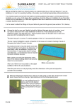
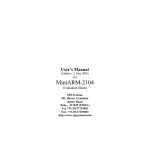
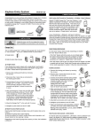
Garage Door MonitorTM
Model GM-318
2. SET UP CODE CONNECTORS AND ZONE CONNECTORS (CONT)
1. INTRODUCTION
The garage door monitorTM is designed to monitor the status of your
garage door and advise you if the door is open. By placing the sensor
on the door panel, you will be alerted when the door is open. When the
garage door is open, receiver will beep and flash.
In this package, you should find a Garage Door MonitorTM Sensor, a
Household Alert® Receiver, an adapter, 3V lithium battery, double-sided
foam tape, mounting accessories and a clip.
“+” on the table means the connec tor for
that position should be placed on the
posts.
“-” on the table means the connector for
that position should be removed.
A
B
Zone 1
+
+
Zone 2
+
-
Zone 3
-
+
Zone 4
-
-
Table 1
3. POWER UP THE HOUSEHOLD ALERT ® RECEIVER AND
TM
GARAGE DOOR MONITOR SENSOR
3V Lithium
battery
Adapter
After setting up all the connectors, both units are ready to be powered up.
Garage Door
MonitorTM Sensor
Household Alert®
Receiver
Clip
4 pcs 3 x 18 screws
1 pc 2 x 5 screw
Double-sided foam tape
Please follow the instructions below to set up your garage door monitor
properly.
Plug in the adapter to the receiver, the green LED will start flashing
indicating the receiver unit is powered up but no sensor is detected.
Push the detection rod to it’s fully retracted position. Remove the battery
cover on the sensor and insert the 3V lithium battery to the sensor as
shown in the diagram.
The LED on the sensor will flash 8 times to indicate the unit is properly
powered and there is signal transmission to the receiver. The green LED
on the receiver will stop flashing and stay on. Make sure to put the
transparent protective cover back in place after setting up.
2. SET UP CODE CONNECTORS AND ZONE CONNECTORS
1. CODE CONNECTORS
In order for the sensor to communicate with the receiver properly, the
sensor’s code must match with the receiver’s code. Code connectors 1
to 6 can be found by opening the battery cover of the sensor and the
back cover of the receiver. Note: Before opening the battery cover, it is
necessary to remove the transparent protective cover. Keep it for future
use. User is required to set these code connectors randomly and the
code settings on the sensor and receiver must be the same. Each
position of the code connector can be set to “+”, “-” or “0” position.
Refer to the diagram below to set the code connectors properly. If the
connector is placed on the top and middle posts, that column is set on
“ + ”. If the connector is placed on the middle and bottom posts, that
column is set on “ - ”. If the connector is removed completely, (not placed
on any posts), it is set to “ 0 ”. (see diagram for examples of how to set a
column to the three different positions).
+
“+” positive
side up
Plug in adapter to the receiver
Insert 3V battery to the sensor
If the green LED on the receiver does not stop flashing, ensure the code
setting on the sensor is identical to the receiver. Position the sensor
vertically to allow the detection rod to drop. One of the LED on the
receiver will flash and the buzzer will also beep. Please put the battery
cover and transparent protective cover back in place.
You can install the sensor onto the garage door.
Note: The receiver may not be able to receive the signal from the
sensor properly if they are too close to each other. Move the sensor
further from the receiver to test again.
Remove transparent
protective cover
Code connectors on sensor
Code Connectors on Receiver
Detection
rod is fully
retracted
‘0’
Detection
rod is fully
extended
Clip
‘+’
‘-’
Note: A connector
can be removed
with the clip,
as shown.
Note: If you experience interference from a nearby system, which could
accidentally trigger your system, please change the code settings on the
sensor and receiver. The code setting on the sensor and receiver should
still match after changing the code setting.
4. INSTALLATION
2. ZONE CONNECTORS
Each receiver can work with up to 4
different sensors (to represent 4
different zones on the receiver).
There are 2 connectors that determine the zone number 1, 2, 3, or 4.
These 2 connectors can be found by
opening the battery cover. Please
follow the chart below to set the zone
number. If the sensor is set to zone
number 1, then the receiver zone 1
signal will correspond to this sensor.
WARNING
Unplug the power cord of your garage door opener
before installation to ensure power is not connected.
Step 1 – Select a spot on your garage door to mount the sensor
Before you install the sensor onto the garage door, make sure the
garage door is closed. The sensor assembly should be mounted on one
of the vertical supports of your garage door near the bottom.
Zone
connectors
When the door is closed, the detection rod should be retracted. When
the door is open, the detection rod will be extended.
4. INSTALLATION (CONT)
8. LOSS OF SIGNAL INDICATION
When the battery level on the sensor drops to a certain level, or the
sensor is out of the operating range, the receiver will show a “loss of
signal” indication. The red LED representing that zone will flash rapidly,
i.e. if zone 1 sensor is lost, the zone 1 red LED will flash rapidly.
When the loss of signal indication occurs, move the receiver closer to
the corresponding sensor and trigger that sensor. If the red LED stops
flashing rapidly, that means the receiver or sensor needs to be relocated.
If the “loss of signal” indication persists, replace the battery of that sensor.
One of
Vertical
Supports
Door closed
Door open
9. OTHER HOUSEHOLD ALERT ® SENSORS
Step 2 – Mount the sensor onto your garage door
The Household Alert® receiver can work with up to 4 different sensors:
garage door monitor sensors, door / window sensors, water sensors,
indoor/outdoor motion sensors, etc. Please visit www.skylinkhome.com
or contact us at [email protected] for more information of how
to fully utilize your Garage Door MonitorTM.
You can mount the sensor onto your garage
door with double-sided foam tape if the surface of your garage door is smooth and clean
enough to provide a good adhesive surface,
such surf ace can usually be found on a me tal
garage door. Please ensure the surface is
smooth and clean. Important: The bottom
of the sensor should be 1/2 inch above
the ground. (Refer to Diagram A)
For w ooden garage doors, it is recommended
to mount the sensor with screws onto the
garage door with 3 x 18 screws provided.
Double-sided
foam tape
4 Screws
Note:
When the garage door is opening/closing,
make sure the sensor does not interfere with
the safety reversing sensor or safety beam
sensor supplied with your existing garage
door opener.
Note: Ensure you straighten up the antenna
on the receiver to receive the best possible
reception.
10. FCC
This device complies with Part 15 of the FCC Rules. Operation is subject to the
following two conditions: (1) This device may not cause harmful interference, and
(2) This device must accept any interference received, including interference that
may cause undesired operation.
WARNING:
Changes or modifications to this unit not expressly approved by the party
responsible for compliance could void the user’s authority to operate the equipment.
1/2 Inch
Diagram A
5. OPERATION
When the garage door is open, the sensor will send a signal to the
receiver. It will beep and the corresponding zone red LED will flash.
If the sensor is set to zone 1, zone 1 red LED on the receiver will flash,
and the receiver will emit a continuous “single beep”, i.e. “beep” pause,
“beep”, pause….. etc.
If the sensor is set to zone 4, zone 4 red LED will flash, and the receiver
will emit a con-tinuous “4 beeps”, i.e. “beep beep beep beep” pause “beep
beep beep beep” pause ……etc.
NOTE:
This equipment has been tested and found to comply with the limits for a Class B
digital device, pursuant to Part 15 of the FCC Rules. These limits are designed to
provide reasonable protection against harmful interference in a residential installation.
This equipment generates, uses and can radiate radio frequency energy and, if not
installed and used in accordance with the instructions, may cause harmful interference to radio communications.
However, there is no guarantee that interference will not occur in a particular
installation. If this equipment dose cause harmful interference to radio or television
reception, which can be determined by turning the equipment off and on, the user is
encouraged to try to correct the interference by one or more of the following measures:
- Reorient or relocate the receiving antenna.
- Increase the separation between the equipment and receiver.
- Connect the equipment into an outlet on a circuit different from that to which the
receiver is connected.
- Consult the dealer or an experienced radio/TV technician for help.
By the number of beeps emitted by the receiver, user can identify which
zone is triggered.
6. BUZZER VOLUME
You can select the buzzer volume by
switching the volume switch to “HI” or
“LO” position.
The buzzer can be disabled by switching
to the “OFF” position.
11. WARNING
To prevent possible SERIOUS INJURY or DEATH from a closing garage door:
- Activate door ONLY when it can be seen clearly, is properly adjusted, and there
are no obstructions to door travel.
- ALWAYS keep garage door in sight until completely closed. NEVER permit
anyone to cross path of closing garage door.
12. WARRANTY
If, within one year from date of purchase, this pro duct should become defective
(except battery), due to faulty workmanship or materials, it will be repaired or
replaced, without charge. Proof of purchase and a Return Authorization are required.
13. CUSTOMER SERVICE
7. MUTE
When a sensor is triggered for a long period of time, you may stop the
buzzer by pressing the mute button. When another signal comes again,
you can disable the buzzer for all currently activated sensors by pressing
the mute button. The receive will beep again if it receives another signal.
For instance, if you are working on your
lawn with the garage door open, you may
want to disable the buzzer for this garage
door only. Then you can press the “Mute”
button after it starts to sound. If any other
sensor is triggered, the receiver will sound
again.
If you would like to order Skylink’s products or have difficulty getting them to
work, please :
1. visit our FAQ section at www.skylinkhome.com , or
2. email us at [email protected] , or
3. call our toll free at 1-800-304-1187 from Monday to Friday, 9 am to 5 pm EST.
Fax (800) 286-1320
CUSTOMER SERVICE
17 Sheard Avenue, Brampton, Ontario, Canada L6Y 1J3
Email:[email protected]
http://www.skylinkhome.com
P/N. 101A201-004 Rev.4
US Patent 6,597,291
©2005 SKYLINK GROUP