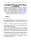
1
User’s Manual
(Edition 1.2, May 2005)
for
MiniARM-2104
Evaluation Board
SPJ Systems
101, Beaver Grandeur
Baner Road
Pune – 411045 (INDIA)
Tel. +91-20-27293002
Fax. +91-20-27293003
http://www.spjsystems.com
Page 2
MiniARM-2104 User’s manual
DISCLAIMER
User’s Manual and other documentation:
This user’s manual and the accompanying
documentation such as schematic diagrams – in soft or
hard form - contains descriptions of copyrighted
products, which are not explicitly indicated as such. The
absence of the trademark symbol does not infer that a
Product is not protected. Additionally, registered patents
and trademarks are similarly not expressly indicated in
these documents.
The information in these documents has been carefully
checked and is believed to be entirely reliable.
However, SPJ Systems assumes no responsibility for any
inaccuracies. SPJ Systems, neither gives any guarantee
nor accepts any liability whatsoever for consequential
damages resulting from the use of these documents or
associated product. SPJ Systems reserves the right to
alter the information contained herein without prior
notification and accepts no responsibility for any
damages that might result. Additionally, SPJ Systems
MiniARM-2104 User’s Manual
Page 3
offers no guarantee nor accepts any liability for damages
arising from the improper usage or improper installation
of the hardware or software. SPJ Systems further
reserves the right to alter the layout and/or design of the
hardware without prior notification and accepts no
liability for doing so.
SPJ Systems
101 , Beaver Grandeur ,
Baner Road ,Baner,
Pune 411045.
India
Phone
: +91 (20) 27293002
Fax
: +91 (20) 27293003
Email
: [email protected]
Web Site: http://www.spjsystems.com
Page 4
MiniARM-2104 User’s manual
Table of Contents
1. INTRODUCTION.....................................................................6
2. GETTING STARTED .............................................................8
2.1 UNPACKING:........................................................................... 8
2.2 POWER SUPPLY REQUIREMENTS:........................................ 8
2.3 CONNECTING THE SYSTEM :.................................................. 9
3. HARDWARE DESCRIPTION ...........................................11
THE MINIARM-2104 SPECIFICATIONS: .................................. 11
4. CONNECTOR DETAILS AND JUMPER SETTINGS
...........................................................................................................14
DESCRIPTION OF ITEMS IN FIGURE 1: ...................................... 17
P1 Connector: .......................................................................18
JP2 Connector:....................................................................18
JP3 Connector:....................................................................19
JP4 Connector:....................................................................20
JUMPER SETTINGS DESCRIPTION : ............................................ 22
5. RUNNING USER PROGRAMS ON MINIARM-2104 23
Page 5
6. OPTIONAL ACCESSORIES OF MINIARM-2104......25
MiniARM-2104 User’s Manual
LCD MODULE:............................................................................ 25
5X5 M ATRIX KEYBOARD:........................................................ 26
W OODEN ENCLOSURE :.............................................................. 26
7. MINIARM-2104 APPLICATIONS....................................28
Page 6
MiniARM-2104 User’s manual
1. Introduction
This is user’s manual for MiniARM-2104
Evaluation Board for LPC2104 micro-controller.
This is a general-purpose board designed as a
development tool; this board has a facility to
download HEX file into the on-chip flash code
memory of the micro-controller.
It is strongly recommended to read this manual
carefully before you start using the MiniARM-2104
board.
CAUTION: This board contains components that
are sensitive to EletroStatic Discharge (ESD). The
board must be handled carefully, so as not to subject
it to ESD. As far as possible, do not touch any
conducting part on the board – including any
component or connector pins – as this may damage
MiniARM-2104 User’s Manual
Page 7
parts of the board permanently. If you must touch
any of the parts, make sure to discharge yourself to
earth. Parts damaged due to ESD are not covered by
the limited warranty.
Page 8
MiniARM-2104 User’s manual
2. Getting Started
2.1 Unpacking:
You will find following items in the package:
• MiniARM-2104 board
• 2 Serial communication cables
• “Y splitter”
• Power adaptor* with cable
• SPJ Systems CD-ROM
*Power adaptor is included only if the board is
shipped in India. If the board is shipped to any
country other than India, only a power jack with a
pair of red and black wires is supplied. The user is
required to provide nominal +9VDC supply across
the 2 wires: Red=positive, Black=negative. This
supply voltage maybe in the range 8 to 11 VDC.
2.2 Power Supply Requirements:
The power adaptor works with 230Volts AC. It
produces approximately 9 Volts DC, and the
MiniARM-2104 uses an on-board regulator to
MiniARM-2104 User’s Manual
Page 9
provide 5 Volts DC to all components on the board.
Other on-board regulators provide 3.3V and 1.8V
DC to LPC2104.
2.3 Connecting the system:
The “Y” splitter should be connected to 9 pin
DSUB connector on the board. The other end of this
“Y” splitter has 2 DB9 connectors, marked “0” and
“1”. The 2 serial communication cables supplied
with the board can be connected to these 2
connectors. Connector marked “0” is the default
serial port of LPC2104 converted to 3 wire RS232
port. This is used for programming the LPC2104
micro-controller by connecting to PC and running
Page 10
MiniARM-2104 User’s manual
appropriate ISP software. Connector marked “1” is
the second serial port of LPC2104 converted to 3
wire RS232 port. Insert the power adaptor output
jack into the on-board power socket. Plug the power
adaptor into 230VAC mains outlet. The system is
now ready to be turned on.
MiniARM-2104 User’s Manual
Page 11
3. Hardware Description
The MiniARM-2104 specifications:
The MiniARM-2104 includes:
1) The processor LPC2104 @ 12 or 14.7456 MHz.
2) LCD interface circuit with 16 pin connector for
connecting text LCD module.
3) Keyboard interface circuit and 12 pin connector
for connecting 5 X 5 matrix keyboard.
4) Two 3 wire RS232 Serial Ports in a single DB9
connector and 2 cables to connect to PC. A “Y
splitter” is also supplied to split the on-board
DB9 connector into 2 separate DB9 connectors
for the 2 serial ports.
5) Regulators to supply 5V, 3.3V and 1.8V to the
MiniARM-2104 board.
Page 12
MiniARM-2104 User’s manual
6) DC adaptor* (230 VAC input, 9 VDC output,
50 mA) which can be directly connected to the
board. [* only included in India]
7) CD-ROM containing:
a) Evaluation version of SPJ Systems’
SCARM – C Compiler for ARM.
b) Sample programs to access LCD, serial port
RTC, etc.
c) LPC2000 ISP software, courtesy of Philips
Semiconductors.
8) Unused / optionally used port pins are available
on convenient connectors.
9) Push-button to reset (re-start) the microcontroller.
10) Toggle switch to change between RUN mode
and ISP mode.
11) 64K I2C compatible EEPROM.
12) I2C compatible Real Time Clock (RTC) with
battery.
MiniARM-2104 User’s Manual
Page 13
Please note, the LCD or keyboard is NOT supplied
with the MiniARM-2104. Those can be bought
separately and connected to MiniARM-2104.
Page 14
MiniARM-2104 User’s manual
4. Connector Details and
Jumper Settings
Figure 1 shows the locations of different
components on the board. The MiniARM-2104
comprises of a baseboard and a daughter-board. The
LPC2104 micro-controller is soldered on the
daughter-board. The dashed polygon in Figure1 is
approximate representation of the daughter-board.
CAUTION: Please do not attempt to separate the
daughter-board from baseboard. Doing so may
cause permanent damage to the board. It will also
make the warranty void.
Page 15
MiniARM-2104 User’s Manual
1
3
4
2
6
13
8
5
7
12
14
8
10
11
9
Page 16
MiniARM-2104 User’s manual
Figure 1: MiniARM-2104 – component locations
MiniARM-2104 User’s Manual
Page 17
Description of items in Figure 1:
1 = Reset Push-button (S2)
2 = Keyboard(5X5 matrix) connector (JP2)
3 = Mode selection switch (Program / Run) (S1)
4 = program mode indicator LED (D2)
5 = Port pins connector (JP3)
6 = Variable resistor for Contrast Adjustment.
7 = Connector for LCD (JP4)
8 = Serial port connector (P1)
9 = Power regulator
10 = Power input socket (JP1)
11 = power-on indicator LED (D3)
12 = DaughterBoard to host LPC2104 µC.
13 = J2 connector for SPI (on the daughter-board)
14 = J1 connector for JTAG (on the daughterboard)
Page 18
MiniARM-2104 User’s manual
Connector Details:
P1 Connector:
This is a DB9 female connector, used for RS232
serial communication with the PC:
Pin 2 = RS232 RxD0 (input to µC)
Pin 3 = RS232 TxD0 (output of µC)
Pin 5 = Ground
Pin 4 = RS232 RxD1 (input to µC)
Pin 6 = RS232 TxD1 (output of µC)
All other pins of P1 are unused.
JP2 Connector:
This connector is designed for connection to 5X5
matrix keyboard, however the same connector can
be used for general purpose I/O or any other
purpose. It essentially contains some port pins and
Vcc and GND. Here is the pin description:
Pin 1 to 8 = P0.22 to P0.29
Pin 9 = P0.30
Pin 10 = P0.31
MiniARM-2104 User’s Manual
Page 19
Pin 11 = GND
Pin 12 = Vcc
The 8 pins of port P0 are pulled-up with on-board
resistors of value 10K.
JP3 Connector:
This is a dual line, 20 pins (10X2) connector.
The pin description is:
Pins 1,2 = Vcc
Pins 3,5,7,9,11,13 = P0.4 to P0.9
Pins 15,17= P0.2, P0.3
Pins 4,6 = P0.1,P0.0
Pins 8,10,12,14,16,18= P0.16 to P0.21
Pins 19,20 = GND
Referring to Figure1, the pin in left-top corner of
JP3 is pin number 1 and right-top corner is pin
number 2. Pins on the left are numbered 1,3,5…19
Page 20
MiniARM-2104 User’s manual
from top to bottom. Pins on the right are numbered
2,4,6…20 from top to bottom.
Port pins P0.2 and P0.3 are also used as SCL and
SDA (respectively) for I2C bus. These pins are also
available on JP3 connector, so user may add more
I2C devices on the same bus externally.
JP4 Connector:
This is a 16 pin, single line connector, designed for
connection to standard, text LCD modules. The
pin/signal correspondence is designed to be
matching with that required by such LCD modules.
Pin 1 = GND
Pin 2 = Vcc
Pin 3 = Vlcd
Pin 4 = P0.15 (Used as RS of LCD)
Pin 5 = GND
Pin 6 = P0.14 (Used as EN of LCD)
Pin 7 to 10 = No Connection
MiniARM-2104 User’s Manual
Page 21
Pin 11 to 14 = P0.10 to P0.13 (Used as D4-D7 of
LCD)
Pin 15 = Backlighting
Pin 16 = GND
J1 Connector:
J1 is 9pins (9X1) connector for JTAG.
The pin description is:
Pin 1 = VDD (3.3V)
Pin 2 = TRST of JTAG /P0.17
Pin 3 = TDI of JTAG/P0.20
Pin 4 = TMS of JTAG/P0.18
Pin 5 = TCK of JTAG/P0.19
Pin 6 = RTCK of JTAG
Page 22
MiniARM-2104 User’s manual
Pin 7 = TDO of JTAG/P0.21
Pin 8 = RST for JTAG
Pin 9 = GND
J2 Connector:
Pin 1 = GND
Pin 2 = SS / P0.7
Pin 3 = MISO / P0.5
Pin 4 = MOSI/ P0.6
Pin 5 = SCK/ P0.4
Pin 6 = Vcc
Jumper Settings Description:
The JP5 jumper on the MiniARM-2104 board can
be used to control LCD backlighting.
JP5 open -> backlighting off.
JP5 short -> backlighting on.
MiniARM-2104 User’s Manual
Page 23
5. Running user programs on
MiniARM-2104
The MiniARM-2104 includes LPC2104 microcontroller. It has 128KBytes of on-chip flash
program memory. Further, this program memory is
In System Programmable (ISP). The ISP software
(courtesy of Philips Semiconductors) is included on
the accompanying CD. It allows the user to
“download” a program (Intel HEX file) directly into
the processor.
Follow these simple steps to download your
program into the µC and run it:
1. Turn off power to the MiniARM-2104.
2. Press the “Mode selection switch” (SW1). It
should stay in the pressed down position.
Page 24
3.
4.
5.
6.
7.
MiniARM-2104 User’s manual
Connect the MiniARM-2104 to the serial port
of PC (COM1 or COM2 etc.). Use the serial
communication cable that was supplied with
the board.
On the PC, run the LPC200 ISP software. This
software is included on the CD that is supplied
with MiniARM-2104. Follow the instructions
given in this ISP software to erase / program
the on-chip flash of LPC2104. When the
software prompts you to reset the processor,
you may momentarily press the RESET switch
on the board.
Turn off power to the MiniARM-2104.
Press the mode selection switch (SW1) once
again. Now it should stay in the “up” position.
Turn on power to the MiniARM-2104 and your
program should run.
MiniARM-2104 User’s Manual
Page 25
6. Optional Accessories of
MiniARM-2104
This chapter describes optional accessories of the
MiniARM-2104 evaluation board:
LCD module:
Number of different types of LCD modules can be
connected to MiniARM-2104. For example: 16 char
X 1 row, 16 char X 2 rows, 16 char X 4 rows and so
on. Most LCD modules use the same pin
connections as connector JP4 of MiniARM-2104.
Hence, a simple one-to-one cable maybe used to
connect such an LCD module to MiniARM-2104.
In case you plan to use an LCD module which has
different pin connections than JP4, then you must
Page 26
MiniARM-2104 User’s manual
not use one-to-one cable. If you buy LCD module
from SPJ, it includes a cable which can be directly
connected to JP4 of MiniARM-2104.
5X5 Matrix Keyboard:
This is a simple matrix keyboard with 25 keys,
organized as 5X5. The JP2 connector of MiniARM2104 is designed to connect to such a keyboard. The
JP2 connector also include Vcc and GND pins,
which are not required by the keyboard. Hence,
only first 10 pins of JP2 maybe directly connected
to 5X5 matrix keyboard. If you buy 5X5 matrix
keyboard from SPJ, it includes a cable which can be
directly connected to JP2 of MiniARM-2104.
Wooden Enclosure:
This is a simple wooden box, very convenient for
mounting the MiniARM-2104 and accessories. If
you buy MiniARM-2104 with this wooden box, the
MiniARM-2104 User’s Manual
Page 27
MiniARM-2104 board is fitted with screws inside
the box. In order to use the board, the box must be
kept open and then you may connect serial cable
and power jack. This enclosure also has sufficient
space for accommodating the 5X5 matrix keyboard
and upto 16X2 LCD module. If you buy MiniARM2104 + LCD + 5X5 Matrix Keyboard + Wooden
Enclosure from SPJ, then all the above will be fitted
inside the Enclosure; only serial cable, power
adaptor and software CD will be outside it.
Page 28
MiniARM-2104 User’s manual
7. MiniARM-2104 Applications
The MiniARM-2104 evaluation board is designed
for using in many different configurations. Some of
them are described here:
1. As a test platform for LPC2104 based
applications. Using the default configuration,
you can download your program (HEX file) into
the on-chip Program memory of the processor
and run it.
2. You can test your program at "real-time" at a
fraction of a cost of an In Circuit Emulator.
3. The sample programs provided with the
MiniARM-2104 evaluation board include
programs to interface with LCD and matrix
keyboard etc. Thus, you can connect the
required peripherals externally and have your
application ready in a short time.
MiniARM-2104 User’s Manual
Page 29
4. To quickly implement “prototype” of any
product.
5. As an experimenting platform for self-learning
or for training.