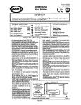
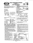
1
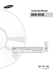
Form # 2482
Date 2-98/~
Model 5434 & 5434KL
3/8"Capacity Straight Drill
-
Mo,del5434TB 7/16"Tke Buffer
IMPORTANT
Read these instructions carefully before Installing, operating, servicing or repairingthis
tool. Keep these Instructions In a safe accessible place.
1
SAFETY MESSAGES
Use
Use
Use
Use
1A
- Safety Gloves
-Safety Boots
- Breathing Masks
- Ear Protectors
YES
1
WARNING
@
<fi)
Always Wear Safety Goggles
A
Avoid ProlongedExposure
o Vibration
wear Hearing Protection
Operator Instructions
I
ores seen
Use
Work Stations
Putting Into Service
Operating
Dismantling and Assembly.
Safety rules when using a 5434 & 5434KL Drill or 5434TB Tire Buffer
- Use may produce flying objects. Always use safety
goggles.
Use accessories rated at W e 2,500 RPM.
Prolonged exposure to vibration may cause Injury.
ReadallInstnxfiCTTCbeforeusingthtetoot.Atopeiatiremust
befuKytainedInitsusaandawareof thesesafety nies.
- Do not exceed the maximum working air pressure.
Use personalprotectionequipment as recommended.
Use compressed air only at the recommended
conditions.
If the tool appears to malfunction, remove from use
Immediatelyand arrange for service and repair.lf h IS not
practicalto remove tool from service, (hen shutoff the air
supply to the toot and write or have written a warning
note and attach it to the toot.
- If tool Is to be used with a balancer or other suspension
device, ensure that the tool is firmly attached to the
suspensidsupport device.
- When operating the tool. always keep the body and
particularlythe hands away from the working,attachment
fixed tothe tool.
- The tool Is not electricallyInsulated. Never use the tool If
there Is any -chance of coming Into contact with live
electricity.
- Always when using the tool, adopt a finn footing and/or
position and grip the tool sufficiently only to 6wrcorne
any reaction forces that may result from the too) doing
work. Do not overgrip.
Use only con-act spare parts for maintenance ancfrepadr.
Do not Improvise or make temporary repairs. Major
servicing and repairs should only be
-
-
-
-
- carriedoutbvnereonstminedtodoso.
not
taps,wire, etc. the WOW
valve In 'Ona position. The throttle
-
and easily accessible so that the alrsupply to the tool can
be shut off In an emergency.
Check hose and fittings regularly (or wear.
- Take care against entanglement of the moving parts of
the tool with clothing, hair, ties, cleaning rags, rings,
jewelry, watches, bracelets, etc.This could cause the body
or parts of the body to be drawn towards and in contact
with the moving parts of the tool and could be very
dangerous.
- It Is expected that users will adopt safe woridng practices
and observa all local, regionalor countrylegalrequirements
when Installing, usingor maintaining(he tool.
- Take care that the exhaust air does not pointtowardsany
other person or material or substance that could be
-3ontaminatedby dl droplets. When firo$lubricatinga tool
or If the toot exhaust has high ofl content, do not allow
the exhaustair to come near very hot surfaces or flames.
Never lay the tool down until the working attachment has
stopped moving.
When the tool is not in use. shut off the air supply and
press throttle triggerAever to drain the supply line. Ifthe
tool Is not to Inused (or a period of time, first lubricate,
disconnectfromair supply and store Inadry average room
temperature environment
If the tool Is passed from one user to a new or Inexperienced usor, make sure these Instructionsare available to
be passedwith the tool.
- Do not remove any manufacturer fitted safety devices
where fitted, I.8.. wheel guards, safety trigger, speed
governors, etc.
-
-
-
7
DO
trigger/ fever, etc. must always be free
to return to the 'Off' position when
released.
Ahvfwsshutoffthealrsupptytothetool
and press the"On/Off valve to exhaust
the air from the lead hose before
fitting, removing or adjusting the
W n g attachment fitted to the tool.
- Beforeusbgthetoolmakesurethata
shut off device has been fitted to the
supply One and the position Is known
-
\
\\--w
RecommendedAir Supply System
Page No 1
Fiqure 1