1
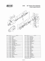
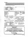
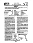
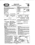
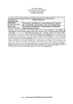
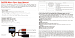
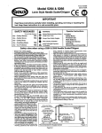
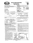
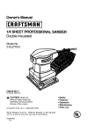
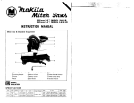
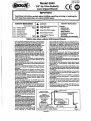
-
Form # Z397
Date 11-97lA
Model 5040
@Câ@
318'' Sq. Drive Butterfly
Lever Impact Wrench
IMPORTANT
Read these instructions carefully before installing, operating, servicing or repairing this
tool. Keep these instructions in a safe accessible place.
2
1A
SAFETY MESSAGES
Use
Use
- Safety Gloves
- Safety Boots
- BreathingMasks
Use - Ear Protectors
Use
YES
1
WARNING
@
Always Wear Safety Goggles
@
~arliearing
Protection
,
&
I
Avoid Pmhged Exposure
To Vibration
Operator Instructions
~ o r e & e nUse
Work Stations
Putting Into Service
Operating
Dismantling and Assembly.
Safety rules when using a 5040 Impact Wrench
- Use oniy impactsockets and extensions, universaljoints,
etc., ratedas baingsuitable for use with impactwrenches.
- Prolonged e-ure to vibration may cause injury.
- Take care that the exhaust air does not point towards any
- Do not exceed the maximum working air pressure.
- Use personalprotectionequipment & r&mended.
-- UIf thes tool
e - d r m & W w m
appears to malfunction, remove from use
-
-
-
-b
R d A i m b a b W W W - N
*Mhbmd6dm**
requirementswhen installing, usingor maintainingthe tool.
m m d
other person or material or substance that could be
contaminatedby oil droplets. When first lubricating a tool
or if the tool exhaust has a high oil content, do not allow
the exhaust air to come near very hot surfaces or flames.
Never lay the tool down until the working attachment has
stopped moving.
When the t d is not in use,shut off the air supply and
press throttle triggerhever to drain the supply line. If the
t d is not to be used for a period of time, first lubricate,
disconnectfrom air supply and store in a dry average room
temperature envirmnt.
If the t d is passed from one user to a new or inexperienced user, make sure these instructionsare availableto
be passed with the t d .
Do not remove any manufacturer fitted safety devices
where fitted, i.e., wheel guards, safety trigger, speed
governors, etc.
Wherever possible, secure workpiece with damps, a vise,
etc. to make it rigid .so it does not move during the work
operation. Keep good balance at all times. Do not stretch
or overreach.
Try to match the t d to the work operation. Do not use a
tool !hat is too light or heavy for the work operation. If in
doubt, seek advice.
In general terms, this tool is not suitable for underwater
use or use in explosiveenvironments seek advice from
manufacturer.
Try to make sure that the work area is dear to enable the
work task to be performed safely, If practical and
possible, try to dear unnecessary obstructions before
starting work.
h a y s use air hose and couplings with minimum working pressure ratings at least 1 1/2 times the maximum
working pressure rating of the tool.
immediatelyand arrange for s e w atxi repair. If it is not
practical to remove t d from service, then shutoff the air
supply to the t d and write or have written a warning
note and attach it to the tool.
If tool is to be used with a balancer or other suspension
device, ensure that the tool is firmly attached to the
suspension/support device.
- When operating the tool, always keep the body and
particularly the hands away from the working attachment
fixed to the t d .
The tool is not electrically insulated. Never use the tool if
there is any chance of coming into contact with live
electricity.
Always when using the t d , adopt a firm footing and/or
position and grip the tool sufficiently only to overcome
any reaction forces that may result from the t d doing
work. Do not overgrb.
- Use only correct $are parts for maintenanceand rew'r.
Do not improvise or make temporary repairs. Maior
servicing and repairs should only be cahed out -by
wrsons trained to do soDo not lock, tape, wire, etc. the 'On/0ff' valve in 'On'
position.The throttle triggerhever, etc. must always be free
to return to the 'Off' position when released.
Awa shut off the air supply to the tool and press the
'0n/&' valve to exhaust the air from the feed hose
before fitting, removing or adjusting the woking attachment fitted to the t d .
Eefore usingthe tool, make sure that a
shut off device has been fitted to the
Ail P i And F i l t i i
supply line and the position is known
and easily accessible so that the air
supply to the t d can be shutoff in an
*W
emergency.
wiul s u w i capacity
C h e C k ~ a n d ~ r e g ~ f G f T~o Maintain
.
U
m
W
~ & ecare against entang~ementof the
-
-
-
-
-
-
-
-
-
-
-
-
- 1
Low Spot To
L.2
-I
Trap Water
Easy To Reach And
nmingpartsofthetcdwihdothing,hair,
-
Take Air From Top
Air T d
m
,%
yw
%
9-am
r l=+c*
b~ts,etc.Tlnscuddcause~body
orpartsofthcJbodytobedmwntuwa~~~
a n d i n ~ ~ t h e ~ ~ o f t h c J
todandcculdbewty~
It is expectedthat users will adopt sfe
working practices and observe all
local, regional or country legal RecommendedAir Supply System
1
Page No 1
Figure 1
Foreseen Use Of The Tool - 5040
The impact wrench is designed for the tightening and I m n i n g of threaded fastener within the range as specified by the manufacturer.
It should only be usedin conjunction with suitable impact type 3W square female drive nut running sockets. Only use sockets w h i i are
of the impact type.
It is allwed to use suitable extension bars, universal joints and socket adaptors b e W n the square output drive of the ratchet wrench
and the female square drive of the socket.
Do not use the tool for any other purpose than that sptxified without consulting the manufacturer or the manufacturet's authorized
supplier. To do $0 may be dangemus.
Never use an impact wrench as a hammer to dislodge or straighten cmss threaded fasteners. Never attempt to modify the tool for other
uses and never modify the t d for even its recommended use as a nutrunner.
Work Stations
The tool shoutd only be used as a handheld, handoperated tool. lt is always recommendedthat the tool is usedwhen stadng on a solid
floor. It can be used in other positions, but before any such use, the operator must be in a secure position having a firm grip and footing
and be aware that when loosening fasteners the t d can m e quite quickly away from the fastener being undone. An allowance must
always be made for this rearward movementso as to avoid the possibility of hand'amhdy entrapment.
Putting Into Service
Air Supply
Use a clean iubtkatedair supply that will give a measuredair pressure at the tool of !XI PSIG (6.2 bar) when the tool is runningwith the
tri~erflW8rfully depressed. Use recammendedhose Size and lenath. It is recommended that the tool is connected to the air supply as
s & m in figure 1. Do not connect the tool to the air line system withzut incorporating an easy to reach and operate air shut off valve.-he
air supply should be lubricated. It is strongly recommendedthat an air filter, regulator, lubricator (FRL)is us& as shown In Figure I as
thii will supply clean, lubricatedair at the correct pressure to the tool. Details of such equipment can be obtained from your supplier. If
such equipment is not used, then the tool shouklbe lubricatedby shuttingoff the air supply to the t d , depressurizingthe line by pressing
the trigger on the t d . D i i n n e c t the air line and pour into the hose adaptor a teaspoonful (5ml) of a suitable pneumatic motor
lubricating oil preferably incorporating a rust inhibiior. Reconnect tool to air supply and run t d slowly for a few seconds to albw air to
circulate the oil. If tool is used freauentlv. lubricate on daii basis and if tool starts to slow or lose mwer.
It is recommended that Wnt tight& &the threaded fasiener assembly be checked with a torque wrench.
It is recommended that the air pressure at the tool while the tool is tunning is 90 PSU6.2 bar.
Operating
The output of the impact wrench in prime working condition is governed by mainly three factors:
a) the input air pressure;
b) the time the impact wrench is operated on the jomt. Normai time for joints of average tension requirement 3 to 5 seconds;
c) the setting of the air regulator for a g h n joint at a given pressure operated for a given time.
The air regulator (47) can be used to regulate the output of the impact wrench if no other means of control is available. It is strongly
recommended that an external pressure regulator, ideally as parlof a filterlregulatorflubricator(FRL), is usedto control air inlet pressure
so that the pressure can be set to help control the tension requid to be applied to the threaded fastener joint.
There is no consistent, reliable toque adjustment on an impact wrench of this type. However, the air regulator can be used to adjust
tomue to the awmximate tiahtness of a known threaded ioint. To set the tool to the desired tome. select a nut or screw of known
tightness of the &me size, t6read pitch and thread condiik as those on the job.Turn air regulatoito low position, apply wrench to nut
and gradually increase power (turn regulatorto admit mom air) until nut moves slightly in the direction it was originally set. The t d is now
set to duplicate that tightness, note regulator setting for future use. When tightening nuts not requiringcritical toque values, run nut up
flush and then tighten an addiional onequarler to onehalf turn ( & i t additional turning is necessary if gaskets are beingclamped). For
additional power needed on disassembly work, turn regulator to its fully open position. This impact wrench is rated a 3/8" bolt size.
Ratingmust be downgraded for spring U bolts, tie bolts, long cap screws, double depth nuts, badly rustedconditionsand spring fasteners
as they absorb much of the impact power. When posdtie, clamp or wedge the bolt to prevent springback.
Soak rusted nuts in penetrating oil and break rust seal before removing with impact wrench. If nut does not start to move in three to five
seconds use a larger size impact wrench. Do not use impact wrench beyond rated capacity as this will drastically reduce tool liie.
NOTE: Actual toque on a fastener is directly relatedto joint hardness, tool speed, conditionof socket and the time the tool is allowed to
immct.
use the simplest possible tool-to-socket hook up. Every connectiona b s o h energy and reduces paver.
The direction of mtationof thii tool Is contmlled by the throttle lever. Be sure that it is knownw h i i side ol the lever has to be pressed to
give the required direction of mtatiin before applying the impact wrench to the joint to be fastened or loosened.
For best resuns:
I ) Always use the correct size impact type socket.
2) Use extra deep sockets in place of extension bars where possible.
3) Do not use oversized, worn or cracked sockets.
4) Hold the wrench so the socket fits squarely on the fastener. Hold the wrench firmly, but not too tightly, pressing slightly forward.
Dismantling & Assembly Instructions
Disconnect tool from air supply.
Pry off rubber nose guard (I) from motor housing (5). Remove oiler screw (3) and O-ring (4) and drain oil from the front end into a suitable
container. Gripthe tool in a vise locatingon the square drive of the anvil (12). Unscrew 2 screws (50)and remove 2 lock washers (49) and
retainerplate (48). Pull out air regulator (47) completewith O-ring (46) being careful not to lose ball (44) and spring (45).Tap pin (36) with
a suitable punchas fas as possible out of the assembly, but still allow the assembly to mtate. It is now necessary to grip the length of the
pin driven throughthe assembly and pull it out taking care not to deform it. LiftOffcollar (37) and pull out inlet bushing (43). O-rings (41)
and (42) may be removed from the stem on inlet bushing (43). Unscrew 2 cap screws (39) and 2 cap screws (40) and remove together
with 4 lock washers (38) to release bat# cap (30)and gasket (29)from the assembly. At this stage, remove throttle lever (7)together with
2 throttie Pins (6). Fmm back cap assembly pulloff 2 plungers (31) and remove 2 Springs (32) and 2 valves (33). It is then possibleto lever
out 2 valve seats (34) and 2 springs (35) taking care to protectthe eyes as the springs can fly out when released. Pull out m t o r pin (22)
and extract the ayembly comprisingof retaining ring (28). rear end plate (26). bearing (27), mtor (24),6 mtor blades (23) and cylinder
(25). Note at this tlme the way the cylinder (25) ir removedand note that it must be reassembledin the same way with the chamfer on the
outside diameter to end face at the fmnt end of the tool. Remove mtor blades (23) from mtor (24), take off retaining ring (28) and pull mtor
(24) through rear end plate (26) and bearing (27) assembly. Using a suitable punch, bearing (27) may be removed from rear end plate
(261, Pull out front end plate (21) complete with O-ring (20) and carefully pry off the O-ring, Remove bearing (17) and oil seal (18) from
front end plate (21). Remove retaining ring (19) from motor housing (5) and take out the complete hammer mechanism. Take off O-ring
(15) from cage (16) to remove hammer (14). 2 cage pins (13) andanvil (12). O-ring (10) may be levered off and O-ring ( I 1) removedfrom
anvil (12). oil seal (2) may be hooked out of and anvil bushing (8) pressed out of motor housing (5).
Page No 2
--
318'' Square Drive Butterfly
Lever Impact Wrench
I
2
3
4
I1
1
1
1
1
1
1
I2
t
13
1
16
17
18
21
22
1
1
24
25
26
I
1
1I
1
67163
67IH
67165
67037
67172
67173
67174
67176
67177
67178
1 Houslng Cover
IOlISeal
1 Plug
1 0-RIM
%
1 Hammer Pin (2Y
,
67190
33
67192
35
36
37
1 Rubber Rlng
1 ZW Sa. Anvil ilwudas
Fh.
" I 0-& 111
-
33
32
1
Plun~er(2y
Piunger Spring [2y
Valve Pin (21'
67191
1
1
..
W~Spdt@(2)"
Rdl Pln
Cdhr
67194
671n5
1
1 Hammer Cage
1
M..I Bearim
...
1 Olt Seal
1
, .
1 Front Plate
46
1
1
67181
67182
1 Motor Pin
47
1 672M 1
1
67184
1
1
1
1
67185
671W
Rotor
1 Cylinder
1 Rear Plate
1
49
54
WSIWMI
-
1 0-Ring
Air Rmulator
67%
LmkWasher (2r
67207
Screw(2)"
N a m Plate ( W O )
67384
*odor Quantityas N M ~
Page No 3
~ ~ w / S u p
SIOUXT d s Inc.
2901 Floyd BouIev&~I
~
Produd T m
3BnSq. Drive Bunerfiy
i
WM
Lever Impact Wrench
i
Serial No.
Model Nomos
USA.
Tel No. W2-2524525
Fax No. 712-2524267
~ Use Of
e
M a m e r Or Support
Product Net Weqht
2.2
bs
1.0
Kg
R
~
NO
I
d
Recommended Hose Bore
Si- Minimum
m6 Ins
8 MIM
-
use- b r m & o m
YES
-
-
-
Noise Levek S a n d Pressure Level 87.0 dWA)
*
Sound Power level 98.0 dWA)
Air ?-re
RemmmndedWorking
Maximum
RecommendedMax.
Hose Length
WFt
I O M
62
6.2
bar
bar
90
W
PSl
PSf
Test Methad: T e d 4 in -dance
with P~~?urop
test wde PbI8NTCl and IS0 Standard 3744
M b W n Level
Less than 2.5 Meters / S&
Test M e t h ~
Tested in accordance with IS0
standards 8662 Parts I & 7
1 A y=w
hlaration of Conformity
Sioux Tools lnc.
2901 Floyd Boulevard, P.O. Box 507, Sioux City, Iowa 51102
a r eu
w our sak rwpns&irwh t nw PMUU
Model 5040 Butterfly Lever Impact Wrench, Serial Number
~
g
m
~
Parts I & 7, Pneurup PN8NTCl
lB6WEEC ~& 9 W W E C Directives
PMinJapan
m