1
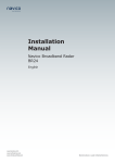
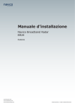
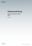
Installation Manual Navico Broadband Radar BR24 English www.lowrance.com www.northstarnav.com. www.simrad-yachting.com Brands by Navico - Leader in Marine Electronics BLANK PAGE Preface Industry Canada Operation is subject to the following two conditions: (1) this device may not cause interference, and (2) this device must accept any interference, including interference that may cause undesired operation of the device. FCC Statement This equipment has been tested and complies with the limits for a Class B digital device, pursuant to Part 15 of the FCC Rules. These limits are designed to provide reasonable protection against harmful interference in a normal installation. This equipment generates, uses and can radiate radio frequency energy and, if not installed and used in accordance with the instructions, may cause harmful interference to radio communications. However, there is no guarantee that interference will not occur in a particular installation. This device must accept any interference received, including interference that may cause undesired operation. If this equipment does cause harmful interference to radio or television reception, which can be determined by turning the equipment off and on, the user is encouraged to try to correct the interference by one or more of the following measures: • Reorient or relocate the receiving antenna. • Increase the separation between the equipment and receiver. • Connect the equipment into an output on a circuit different from that to which the receiver is connected. • Consult the dealer or an experienced technician for help. • A shielded cable must be used when connecting a peripheral to the serial ports. Changes or modifications not expressly approved by the manufacturer could void the user’s authority to operate the equipment. Introduction to the Navico Broadband radar system | 1 CE Compliance Hereby, Navico Auckland Ltd. declares that this BR24 is in compliance with the essential requirements and other relevant provisions of Directive 1999/5/EC. Navico Auckland Ltd. vakuuttaa täten että BR24 tyyppinen laite on direktiivin 1999/5/EY oleellisten vaatimusten ja sitä koskevien direktiivin muiden ehtojen mukainen. Hierbij verklaart Navico Auckland Ltd. dat het toestel BR24 in overeenstemming is met de essentiële eisen en de andere relevante bepalingen van richtlijn 1999/5/EG. Par la présente, Navico Auckland Ltd. déclare que ce BR24 est conforme aux exigences essentielles et aux autres dispositions de la directive 1999/5/CE qui lui sont applicables. Härmed intygar Navico Auckland Ltd. att denna BR24 står i överensstämmelse med de väsentliga egenskapskrav och övriga relevanta bestämmelser som framgår av direktiv 1999/5/EG. Undertegnede Navico Auckland Ltd. erklærer herved, at følgende udstyr BR24 overholder de væsentlige krav og øvrige relevante krav i direktiv 1999/5/ EF. Hiermit erklärt Navico Auckland Ltd., dass sich dieses BR24 in Übereinstimmung mit den grundlegenden Anforderungen und den anderen relevanten Vorschriften der Richtlinie 1999/5/EG befindet. (BMWi) Με την παρουσα Navico Auckland Ltd. δηλωνει οτι BR24 συμμορφωνεται προς τις ουσιωδεις απαιτησεις και τις λοιπες σχετικες διαταξεις της οδηγιας 1999/5/ΕΚ. Con la presente Navico Auckland Ltd. dichiara che questo BR24 è conforme ai requisiti essenziali ed alle altre disposizioni pertinenti stabilite dalla direttiva 1999/5/CE. Por medio de la presente Navico Auckland Ltd. declara que el BR24 cumple con los requisitos esenciales y cualesquiera otras disposiciones aplicables o exigibles de la Directiva 1999/5/CE. Navico Auckland Ltd. declara que este BR24 está conforme com os requisitos essenciais e outras provisões da Directiva 1999/5/CE. The equipment named in this declaration, is intended for use in international waters as well as coastal sea areas administered by countries of the E.U. and E.E.A. 2 | 0BIntroduction to the Navico Broadband radar system Radar Transmit Emissions This is the first marine recreational radar that has Human Exposure Level RF Radiation of the Radar Transmitter outside the Radome well below the general public safety emission level of 1 mW/cm2 . This means the radar can be mounted safely in locations impossible with other pulse radars. The broadband radar will not trigger X Band radar transponders, beacons, and SARTs due to the low output power and signal properties. If a pulse radar and Broadband radar are mounted on the same vessel, do not transmit simultaneously as excessive interference is possible. Disclaimer As Navico is continuously improving this product, we retain the right to make changes to the product at any time which may not be reflected in this version of the manual. Please contact your nearest distributor if you require any further assistance. It is the owner’s sole responsibility to install and use the instrument and transducers in a manner that will not cause accidents, personal injury or property damage. The user of this product is solely responsible for observing safe boating practices. NAVICO HOLDING AS. AND ITS SUBSIDIARIES, BRANCHES AND AFFILIATES DISCLAIM ALL LIABILITY FOR ANY USE OF THIS PRODUCT IN A WAY THAT MAY CAUSE ACCIDENTS, DAMAGE OR THAT MAY VIOLATE THE LAW. Governing Language: This statement, any instruction manuals, user guides and other information relating to the product (Documentation) may be translated to, or has been translated from, another language (Translation). In the event of any conflict between any Translation of the Documentation, the English language version of the Documentation will be the official version of the Documentation. This manual represents the product as at the time of printing. Navico Holding AS. and its subsidiaries, branches and affiliates reserve the right to make changes to specifications without notice. Copyright © 2009 Navico Holding AS. Warranty The warranty card is supplied as a separate document. It is shipped with the product registration card. In case of any queries, refer to the brand web site of your display or system. www.lowrance.com www.northstarnav.com www.simrad-yachting.com Feedback from you Your feedback is important and helps Navico ensure that this manual is a valuable resource for all marine technicians. E-mail your comments or suggestions about this manual to the following address: [email protected] Introduction to the Navico Broadband radar system | 3 Contents 1 Introduction to the Navico Broadband radar system ................................... 5 Welcome ..................................................................................................... 5 What is Broadband radar? .............................................................................. 6 Radar system overview.................................................................................. 8 2 Install the radar........................................................................................... 9 Choose the scanner location ......................................................................... 10 Mounting the scanner .................................................................................. 11 Mounting the radar interface box .................................................................. 12 3 Wiring the radar system ............................................................................ 13 Connect interconnection cable to the scanner ................................................. 13 Connect the interconnection cable to radar interface box .................................. 14 Connect the Broadband radar to your display.................................................. 16 HDS (USA only)...................................................................................................16 HDS (Non USA) ...................................................................................................16 HDS NMEA 2000 Heading......................................................................................16 NX40, NX45 ........................................................................................................17 M84, M121 .........................................................................................................17 NX40, NX45 SimNet Heading.................................................................................17 M84, M121 NMEA 0183 Heading ............................................................................17 GB40 .................................................................................................................18 GB40 SimNet Heading ..........................................................................................18 8000i .................................................................................................................19 8000i NMEA 0183 Heading ....................................................................................19 8000i SimNet / NMEA2000 Heading........................................................................19 Connect power ........................................................................................... 20 4 Configure displays to use radar ................................................................. 21 Lowrance HDS radar setup ........................................................................... 21 Simrad GB40 / Northstar 8000i radar setup .................................................... 22 Simrad NX40/45 or Northstar M84/M121 radar setup....................................... 23 5 Drawings ................................................................................................... 24 Scanner dimensions .................................................................................... 24 Radar interface box..................................................................................... 25 6 Maintenance .............................................................................................. 26 7 BR24 BroadBand radar scanner specifications ........................................... 27 Navico Broadband radar part numbers ........................................................... 28 RF exposure compliance certificate ................................................................ 29 4 | 0BIntroduction to the Navico Broadband radar system 1 Introduction to the Navico Broadband radar system Welcome Congratulations of your purchase of the latest technology available in recreational marine radar. The special features designed into this radar are: • “Revolutionary improvement in situational awareness” Provides unprecedented ability to distinguish hazards and other objects • Radar is finally easy enough for casual users – identifies targets clearly with out complicated tuning adjustments. • Navigation with unparalleled resolution and clarity at close ranges, where traditional radar completely obscures targets. • “Start faster, go longer” - 100% solid state design – no powerful microwave transmitter required! – provides InstantOn™ power up capability and low power consumption • Eliminate the 2-3 minute warm-up time typical of traditional radars • Conserve power with a standby drain less than one tenth of the best existing radars – especially great for sailboats and smaller power boats • No expensive magnetron replacement is ever required • “Incredibly approachable” - practically imperceptible transmit emissions are extremely safe, allowing you to mount it anywhere • Less than 1/10th the transmitted emissions of a mobile phone, can be safely mounted in proximity to passengers • Compatible with a wide range of Navico multi-function displays and heading sensors 0BIntroduction to the Navico Broadband radar system | 5 What is Broadband radar? The Navico Broadband radar uses FMCW (Frequency Modulated Continuous Wave) radar technology. What is FMCW? The current normal leisure radar generates microwave pulses with a thermionic device called a magnetron. This ancient technology transmits bursts of high power microwave energy periodically, and the radar detector listens to the echoes coming back from each pulse. As the radar rotates, these echoes are built into a 360 degree image. FMCW radar is different: Firstly it is solid state – i.e. the transmitter is a semiconductor device, not based on magnetron technology. Secondly, it transmits a 1ms long signal of increasing frequency, rather than a short duration pulse. Thirdly, it measures the distance to a target not by timing the returned echoes, but by measuring the difference between the current transmitted frequency and echoed frequency. Hence FMCW – Frequency Modulated Continuous Wave. The building up of the image over 360 degrees and the processing of the radar data is the same as for a magnetron radar. How does FMCW radar work? FMCW = Frequency Modulated Continuous Wave The scanner transmits a ‘rising tone’ (Tx wave) with linearly increasing frequency. The wave propagates out from the transmitter retaining the frequency it had when it was transmitted. If it reflects off an object, it will return to the receiver, still at the frequency it had when originally transmitted. Meanwhile, the transmitter continues to output an increasing frequency. The difference between both the currently transmitted and received frequencies, coupled with the known rate of frequency increase, allows a time of flight to be calculated, from which distance is calculated. 6 | 0BIntroduction to the Navico Broadband radar system Additional benefits of FMCW radar are: Safety: • low energy emissions. 1/10th of a mobile phone • safe operation in anchorages and marinas • instant power up. No warm up required Short range performance • broadband radar can see within a few meters of the boat, compared to pulse radars which can not see closer than 30 meters • higher resolution clearly separates individual vessels and objects • Up to five times better sea and rain clutter performance Low power • suitable for small boats and yachts • easier installation with lighter cabling • great for yachts on ocean passage Instant power-up • conventional radars take 2-3 minutes to heat up the filament: Safety – 2 minutes is a long time if you are concerned about collision; and • convenience – switch it on and use it. Easy to use • no constant adjusting required to obtain optimum performance • no re-tuning between ranges. Means fast range change at all ranges. 0BIntroduction to the Navico Broadband radar system | 7 Radar system overview The Navico Broadband radar is a state of the art navigation aid. It provides outstanding radar performance without the limitations of conventional pulse radars such as: dangerous high power microwaves, standby warm up time, 30 m blind spot (mainbang), high power consumption and large open arrays - which is what would be required to obtain the same image quality at shorter ranges. The Navico Broadband radar has an effective range from 200 ft to 24 nm and has an operating power consumption of 19 W and stand-by power consumption of 2 W. The system consists of: radar scanner, an interface box and an interconnection cable. The scanner is housed in a dome of similar size to most 2 kW radars on the market. The interface box is used to connect displays, power and heading information. There are two models: RI10 and RI11. Depending on the display system used, the main difference is that one has a SimNet (Simrad NMEA 2000) connector for heading input (RI10). The other interface box (RI11) has a connector to interface to RS422 displays and NMEA 0183 heading sensors. Both interface boxes have a Network connector to interface to Ethernet displays. Lowrance HDS units sold in the USA do not require an interface box and the scanner connects directly to the display or Ethernet switch Brand Model Radar interface box used Data connection protocol Chart overlay MARPA Lowrance HDS USA N/A Ethernet Yes* No Lowrance HDS R.O.W RI11 Ethernet Yes* No Simrad GB40 RI10 Ethernet Yes* Yes** Northstar 8000i RI11 Ethernet Yes* Yes** Northstar 8000i + N2k RI10 Ethernet Yes* Yes** Northstar M series RI11 RS422 Yes* No Simrad NX40/45 RI11 RS422 Yes* No *For best chart overlay performance use a heading sensor. Course over ground can be used but only when moving ** For MARPA it is essential to use a heading sensor with an output speed of 10 Hz. Heading sensor needs to be a rate gyro stabilized compass or better. 8 | 0BIntroduction to the Navico Broadband radar system 2 Install the radar Installation includes: • Mechanical mounting • Electrical wiring • Configuring the display or network system to work with the radar • Adjusting the radar for proper performance Follow these instructions carefully. Don't take any shortcuts! The broadband radar is factory sealed. It is not necessary to remove the cover. Removing the cover will void the factory warranty. This section explains how to: • Choose the correct location for the scanner • Install the scanner on a power boat or a yacht • Choose the correct location for the radar interface box if one is required • Install the radar interface box (if required) Please take a moment and check the separate packing list to make sure all components have been supplied 1BInstall the radar | 9 Choose the scanner location The radar's ability to detect targets greatly depends on the position of its scanner. The ideal location for the scanner is high above the vessel's keel line where there are no obstacles. A higher installation position increases the radar ranging distance, but it also increases the minimum range around the vessel where targets cannot be detected. When you're deciding on the location, consider the following: • The length of the interconnection cable supplied with your radar is usually sufficient. If you think you'll need a longer cable, consult your dealer before installation. Optional cable lengths are 10 m (33 ft), 20 m (65.5 ft) and 30 m (98 ft). • If you mount the scanner on a pedestal or base, ensure that rain and sea spray can drain away rapidly, and the breather hole in the base can operate . • The scanner is usually installed parallel to the line of the keel. DON'T DO THIS! • DON'T install the scanner too high up, which may cause degradation of the radar picture over short ranges. • DON'T install the scanner close to lamps or exhaust outlets. The heat emissions may damage the dome. Soot and smoke will degrade the performance of the radar. • DON'T install the scanner close to the antennas of other equipment such as direction finders, VHF antennas, GPS equipment as it may cause interference. • DON'T install the scanner where a large obstruction (such as an exhaust stack) is at the same level as the beam, because the obstruction is likely to generate false echoes and/or shadow zones. • DON'T install the scanner where it will be subjected to strong vibrations because these vibrations could degrade the performance of the radar. • DON’T install the scanner such that boat electronics with switch mode power supplies (such as fish-finders and chart plotters) are in the beam of the antenna. Minimum distance to install near the ships compass is 0.7 m (3.3 ft). It is recommended not to install the scanner on the same beam plane as a conventional pulse radar. A pulse radar must be set to STBY or OFF when the BR24 is being operated. If possible ensure that the location site provides the scanner with a clear view all round the vessel. Installations on power boats that have a steep planing angle, it is recommended to tilt the scanner angle down at the front. (Beam angle is 12.5° either side of center). 10 | 1BInstall the radar Mounting the scanner • Use the supplied mounting template and tape it securely to the chosen location site. • Before drilling, check that: - you have oriented the mounting template correctly so that the front of the scanner unit will face the front of the vessel - the location site is not more than 18 mm (0.7") thick. If the location site is thicker use longer bolts The four bolts supplied are M8 x 30 mm. If you need to use longer bolts make sure they are marine grade stainless steel and allow for minimum of 8 mm (0.3") and maximum of 18 mm (0.7") of thread contact. • Use a 9.5 mm (3/8") drill bit to drill the four holes where shown on the mounting template. • Remove the mounting template. • Connect the scanner interconnection cable (see "Connect interconnection cable to the scanner" page 13) • Route the connection cable through the cable retention channel. • Position the scanner carefully over the bolt holes so that they are aligned. • Place a lock washer and a plain washer onto each bolt, as shown. • Insert bolt into drill hole and locate into scanners threaded mounting holes and tighten securely. The torque settings for the mounting bolts are 12 Nm – 18 Nm (8.9 lb ft – 13.3 lb ft) 1BInstall the radar | 11 Mounting the radar interface box 12 | 1BInstall the radar • Install the radar interface box (where applicable) in a dry location away from spray, rain, drips and condensation. • The radar interface box must be located where it can be easily connected to the ship's power source, the scanner interconnection cable, and the display or display network. • Allow enough room for cables to form a drip loop. • Preferably mount the radar interface box on a vertical surface with cables exiting downwards. • Insert connectors (see "Connect the interconnection cable to radar interface box" page 14). • Secure to the surface using the four mounting points. 3 Wiring the radar system Connect interconnection cable to the scanner The scanner interconnection cable connects the scanner to the RI10 or RI11 interface box (or Lowrance HDS U.S only). The cable connects to the scanner using a 14 pin connector. Protect the connectors when pulling cable through the boat and avoid putting strain on to the connectors. The interconnection cable is 9 mm in diameter. A 14 mm hole will be required in order for the RJ45 connector to pass through (Interface box end) or 24 mm for the scanner end connector. • Run the interconnection cable between the scanner and the location of the radar interface box. • Insert cable connector on to the male 14 pin plug on the scanner. • Take care to align the connector correctly to avoid bending the pins. Secure the locking collar by rotating clockwise until it clicks. • Feed and secure the cable into the cable retention channel. Scanner Interconnection cable pin out Pin-out Scanner connector Conn Wire color 1 Black RJ45 Tinned wire 2 Red Tinned wire 3 Yellow Tinned wire 4 Drain Tinned wire Cable connector 5 N/A N/A Diameter = 23 mm 6 Blue RJ45 Pin 4 7 White / Blue RJ45 Pin 5 8 White / Brown RJ45 Pin 7 9 Brown RJ45 Pin 8 10 White / Green RJ45 Pin 3 11 N/A N/A 12 White / Orange RJ45 Pin 1 13 Green RJ45 Pin 6 14 Orange RJ45 Pin 2 2BWiring the radar system | 13 Connect the interconnection cable to radar interface box To connect interconnection cable to Lowrance HDS (USA only) (see "Connect the Broadband radar to your display" page 16) 1. Slide (F), (E) and (D) over the RJ45 and data wires of the scanner interconnection cable (G). 2. Connect RJ45 and data wires to the radar interface box. 3. Secure (D) to the radar interface box using the four supplied screws (H). 4. Slide (E) along the cable (G) and press into the cable gland housing (D). Key Description A Radar interface box B Radar data connector RJ45 C Power wires (see "Connect power" page 20) D Cable gland housing E Gland washer F Lock nut G scanner interconnection cable H Screws x 4 M3x12 mm Phillips pan head 5. Rotate (B) clockwise to secure. To remove the scanner interconnection cable, follow the above procedure in reverse order. To avoid damaging the connectors when removing the scanner interconnection cable, it is important to remove the cable gland washer before trying to remove the cable gland housing. 14 | 2BWiring the radar system Shortening the cable It is not recommended to shorten the cable, but if it is essential, use the pin-out below to reterminate the RJ45 connector RJ45 Connector RJ45 crimping tool is required RJ45 Connector Pin Color 1 White/Orange 2 Orange 3 White/Green 4 Blue 5 White/Blue 6 Green 7 White/Brown 8 Brown 15 mm Heat shrink (10 mm dia) 2BWiring the radar system | 15 Connect the Broadband radar to your display HDS (USA only) Broadband radar scanner Adapter cable 000-0127-56 2 m (6 ft) Optional Lowrance 5 Port Ethernet switch. HDS Display ENET Port NEP-1 Lowrance broadband radar in the United States does not require a radar interface box. The scanner connects directly the display or Ethernet switch via the adapter cable. HDS (Non USA) RI11 Ethernet cable NETWORK port 000-0127-28 2 m (6 ft) Optional Lowrance 5 port Ethernet switch. HDS Display ENET port NEP-1 Lowrance Broadband radar outside the USA requires a RI11 interface box. This connects to HDS display via Ethernet either directly into the ENET port on the display or by using an optional 5 port Ethernet switch. An additional Ethernet cable will be required. HDS NMEA 2000 Heading SimNet heading sensor FC40 or RC42 SimNet to NMEA2000 adapter cable. 000-0127-45 16 | 2BWiring the radar system HDS NMEA 2000 port NX40, NX45 M84, M121 RI11 Data cable NX or M series COMMS port AA010114 3 m (9.8 ft) RADAR port Connects to NX40/45 or M84/121 via RS232 using the supplied data cable. NX40, NX45 SimNet Heading SimNet heading sensor AT40 or AT45 SimNet to NMEA 0183 converter FC40 or RC42 NX40 or NX45 GPS port Optionally, for accurate radar chart overlay, a heading sensor on the SimNet backbone passes through the AT40 or AT45 which connects to the GPS port on the NX display. M84, M121 NMEA 0183 Heading NMEA 0183 heading sensor Junction box RI11 Connection kit AA010112 M84 or M121 Display COMMS port Consisting of cables, AA010114/15/16 Radar port Optionally, for accurate radar overlay use an NMEA 0183 heading sensor. Use optional connection kit. 2BWiring the radar system | 17 GB40 RI10 NETWORK port Adapter cable GB40 Ethernet cable 000-0127-56 2 m (6 ft) AA010079 8 port Ethernet linker or (cross-over cable) GB40 NETWORK port AA010009 (AA010084) 0.6 m (2 ft) Connects to GB40 system via Ethernet. Connect a GB40 Ethernet cable in between 8 port Ethernet linker (or crossover cable) and supplied adapter cable. Use only GB40/8000i Ethernet cables. (Order separately) Max Ethernet cable length from RI10 box to switch/display is 50 m. GB40 SimNet Heading SimNet heading sensor RI10 GB40 NavComputer FC40 or RC42 SimNet port SimNet port For MARPA functionality on GB40, heading information at 10 Hz needs to be sent to both the RI10 and the GB40 NavComputer. Connect a SimNet drop cable from the Simnet backbone to the RI10 and connect to the COMS port (SimNet connector). For connecting NMEA 0183 heading data to GB40 see 8000i NMEA 0183 Heading section below. 18 | 2BWiring the radar system 8000i 12" Display processor or Black box processor RI11 Adapter cable Ethernet cable NETWORK port 000-0127-56 2 m (6 ft) 0.6 m (2 ft) AA010079 8 port Ethernet linker (or cross-over cable) 8000i NETWORK port AA010009 (AA010084) Connects to 8000i system via Ethernet. Connect 8000i Ethernet cable in between 8 port linker (or crossover cable) and supplied adapter cable. Use only 8000i/GB40 Ethernet cables. (Order separately) Max Ethernet cable length from RI11 box to switch/display is 50 m. 8000i NMEA 0183 Heading 12" Display processor, Black box processor, or Simrad GB40 not using a SimNet heading sensor NMEA 0183 Heading Sensor Junction Box RI11 8000i NavComputer COMMS port Utility port For MARPA functionality, heading information at 10 Hz needs to be sent to both the RI11 and the master NavComputer. Use the 12 pin cable AA010070 cable from both units to a junction box to share the same heading source. (1x AA010070 ships with 8000i/GB40. Order separately for BR24) 8000i SimNet / NMEA2000 Heading 12" Display processor, Black box processor connecting to a SimNet or NMEA2000 heading sensor Heading sensor AT10HD RI11 AT10 FC40 or RC42 24006694 COMMS 24005936 Junction box 8000i NavComputer Utility port For MARPA functionality, heading information at 10 Hz needs to be sent to both the RI11 and the master NavComputer. AT10HD (optional) connects to RI11 providing fast heading from SimNet or NMEA 2000 backbone. AT10 (optional) connects to the 12 pin Utility cable (AA010070) of the 8000i. 2BWiring the radar system | 19 Connect power The Broadband radar can operate on 12 or 24 V DC systems. The Broadband radar requires a +V DC to be applied on the yellow power on wire in order to operate. This can be achieved in one of three ways. • Common the red and yellow wire together. Radar will power on when power is applied • Use ignition or install a switch that will provide power to the yellow wire. (It is recommended to use a 5 amp fuse or breaker). The radar will turn on when switch is activated • Connect the yellow wire to external wake up of suitable display. Radar will turn on when display is turned on Before connecting power to the system: • Make sure the scanner has been installed and is secured. • Make sure the scanner interconnection cable is connected to the scanner. • If using the Radar Interface Box make sure all connections have been made to the display. For systems using a radar interface box • Connect the red wire to power positive 12 or 24 V DC. Use a 5 amp fuse or breaker. • Connect the yellow wire to power source that will turn on the system (see above). • Connect black to power negative. For systems not using radar interface box (Lowrance HDS USA only) • Connect the red wire to power positive 12 or 24 V DC. Use a 5 Amp fuse. • Connect the yellow wire to power source that will turn on the system (see above). • Connect black to power negative. 20 | 2BWiring the radar system 4 Configure displays to use radar Setup and configuration of the Broadband radar has been simplified compared to traditional pulse radars. There is no zero range (time delay), no warm up time, and no burn in required.. The only adjustments needed are: • Set the scanner height: This is to help the radar calculate for sea clutter. • Adjust the heading marker. This is to align with the heading marker on the screen with the center line of the vessel, this will compensate for any slight misalignment of the scanner during installation. Any inaccuracy will be evident when using MARPA or chart overlay. Lowrance HDS radar setup Enter radar installation by pressing Menu > Settings > Radar > Installation. To set the antenna height: • Use the Up / Down arrows to select antenna height from the menu. Use the Left / Right arrows to adjust the antenna height value. The value will represent the antenna height above sea level in the units that have selected such as feet or meters. To start the radar: • Press pages > Radar > Radar State. Use cursor to edit the radar state. Select transmit to activate the radar. To adjust the bearing alignment: • Use the Up / Down arrows to select bearing alignment. • Use the Left / Right arrows to adjst bring the heading line on the screen to represent the actual heading of the boat. • Point the boat to the end of a head land or peninsular. Adjust the bearing alignment so the heading line touches the end of the same head land or peninsular. For more operational information please refer to the HDS operation guide. 3BConfigure displays to use radar | 21 Simrad GB40 / Northstar 8000i radar setup To set antenna height • Select Pages (Display 8000i) > Setup > Radar. • Press edit and key in the height of the scanner above sea level in feet or meters depending on system units setting. • Select Return. To Transmit • From the radar page select Radar Mode. • Select Transmit. To change the radar bearing alignment: • Select Pages (Display 8000i). If you: - don't have a page that shows the Radar screen in one window and the Chart screen in the other window, edit or create a page that shows these two windows. - do have a page that shows the Radar screen in one window and the Chart screen in the other, select it. • Check that the Chart has the Radar Overlay turned On. • Select the Radar window so that it becomes active. If you can't see the Adjust Radar button, select Return. • Select Adjust Radar, then select Installation. • The Bearing Alignment button shows the current setting. Select it to change the setting. Use the Up and Down buttons to move the radar image one degree at a time, until the radar overlay is aligned with the chart. • Select OK. • Select Return. Accurate heading data is required Your display may need a software upgrade to get full functionality of the Broadband radar. Please contact your dealer for further information. 22 | 3BConfigure displays to use radar Simrad NX40/45 or Northstar M84/M121 radar setup Your display may need a software upgrade to get full functionality of the Broadband radar. Please contact your dealer for further information. To enable the radar functionality: • Press Setup (NX) or menu twice to display the Setup menu, then select System. • Set Radar to . When the radar is enabled, it will turn on, and enter standby mode. Antenna height • Press Menu twice > Radar > Installation Select Antenna height then enter the height of the antenna above sea level. Zero bearing Adjust this on a chart window with the radar overlay on. • Press Menu twice > Radar > Installation • Select Zero bearing then use the arrow keys to enter the new bearing angle. Accurate heading data is required Your display may need a software upgrade to get full functionality of the Broadband radar. Please contact your dealer for further information. 3BConfigure displays to use radar | 23 5 Drawings Scanner dimensions Key 24 | 4BDrawings Description A Cable entry area B Cable retention channel C Bolt holes x 4 M8 x 30 mm D Breather Radar interface box 4BDrawings | 25 6 Maintenance Clean the radome using soapy water and a soft cloth. Avoid using abrasive cleaning products. Do not use solvents such as gasoline, acetone, M.E.K etc. as this will damage the dome surface. After years of use the drive belt may have to be replaced. Transmitter is solid state and will not require regular replacement as with an ordinary magnetron. 26 | 5BMaintenance 7 BR24 BroadBand radar scanner specifications Characteristic Technical Data Compliance FCC Part 80 and Part 90; FCC ID: RAYBR24 IC ID: 4697A-BR24, CE Mark Environmental IEC60945 4th edition 2002-2008 Operating Temperature: -25° to +55°C (-13° to +130°F) Relative humidity: +35° C (95° F), 95% RH Waterproof: IPX6 Relative wind velocity 51 m/sec (Max:100 Knots) Power consumption (with 10 m cable) Operating: 19 W (Typ.) @ 13.8 Vdc Standby: 2 W (Typ.) @ 13.8 Vdc ~ 150 ma DC input (at end of radar cable) 9 V to 31.2 V DC (12/24 Volt systems). Reverse polarity protection Transmitter Source (Pre-heating time ) No magnetron - Instant ON Outside dimensions Height 280 mm x Diameter 489 mm (Height 11" x Diameter 19.3" ) Weight (no cable) 7.4 kg (16.31 lbs) Radar and Antenna Parameters Radar Ranges 50 m (200 ft) to 24 nm with 17 range settings (nm/sm/km) Rotation 24 rpm +/- 10% Transmitter frequency X-band - 9.3 to 9.4 Ghz Transmitter source (warmup time) No Magnetron - all solid state. Instant ON Plane of polarization Horizontal polarization Transmitter peak power output 100 mW nominal Main bang dead zone None- not a pulse radar Sweep Repetition Frequency 200 Hz Sweep Time 1 ms Sweep Bandwidth 70 MHz max Horizontal Beam width (Tx and Rx antenna) 5.2° +/- 10% (-3dB width) Vertical Beam width (Tx and Rx antenna) 25°+/-20% (-3dB width) Side lobe level (Tx and Rx antenna) Below -18 dB (within ±10°);Below -24dB (outside ±10°) Noise figure Less than 6 dB Comms/Cabling/Mounting Comms Protocol High speed Ethernet or Serial Heading NMEA0183 / NMEA2000 / SimNet with interface box Inter Connecting cable standard lengths (display dependant) Lowrance 10 m (33 ft) AA010211 Simrad, Northstar 20 m (65.6 ft) AA010212 Maximum Inter Connecting cable length 30 m (98.5 ft) optional cable AA010213 Bolts (4) M8 x 30 mm - 304 stainless steel Footprint W233 mm (9.17") (port / starboard) x L141.5 mm (5.55") (matches Garmin GMR18HD / Raymarine RD218 footprint) Compatible Displays Simrad GB40 - 10”, 15” Simrad NX40/45 - 8”, 12” Northstar 8000i - 12”, 15” Northstar M84/M121 - 8”, 12” Lowrance HDS - 5”, 7”, 8”. 10" ** Specifications subject to change without notice. 6BBR24 BroadBand radar scanner specifications | 27 Navico Broadband radar part numbers Broadband radar scanner part numbers Model Part Number Description Length Scanner BR24 AA010186 Broad band radar scanner RI10 AA010189 Broadband radar SimNet interface box RI11 AA010204 Broadband radar serial interface box AA010211 Broadband scanner interconnection cable 10 m (33 ft) AA010212 Broadband scanner interconnection cable 20 m (65.6 ft) AA010213 Broadband scanner interconnection cable 30 m (98.5 ft) 000-00127-56 Adapter cable: yellow Ethernet male to RJ45 female 2 m (6.5 ft) AA010079 Navico Ethernet cable for GB40 and 8000i 0.5 m (1.6 ft) AA010080 Navico Ethernet cable for GB40 and 8000i 2 m (6.5 ft) AA010081 Navico Ethernet cable for GB40 and 8000i 5 m (16.4 ft) AA010082 Navico Ethernet cable for GB40 and 8000i 10 m (33 ft) AA010083 Navico Ethernet cross-over cable F/F for GB40 and 8000i 0.3 m (1 ft) 000-00127-28 Navico Ethernet cable E-Yellow-E-Yellow for Lowrance 0.6 m (2 ft) AA010070 Utility cable, 12 pin F / tinned wires for GB40/8000i 2 m (6.5 ft) AA010114 HD serial comms cable for NX40/45 and M84/121 3 m (9.8 ft) Interface boxes Scanner cables Ethernet cables Data cables NMEA - SimNet Converters AT10 24005936 AT10 NMEA0183 / SimNet converter AT10HD 24006694 AT10HD NMEA0183 / SimNet converter. 10 Hz heading data only 28 | 6BBR24 BroadBand radar scanner specifications RF exposure compliance certificate 6BBR24 BroadBand radar scanner specifications | 29 30 | 6BBR24 BroadBand radar scanner specifications 6BBR24 BroadBand radar scanner specifications | 31 BLANK PAGE BRDR24 MountingTemplate Template BR24 Mounting 1:1 A4 version A4 1:1 version 141.5 mm (5-9/16”) Check scale:-Measure before drilling Drill 9.5mm (3/8”) holes 233 mm (9-5/32”) Check scale:-Measure before drilling TO FRONT OF BOAT BR24 base Max 18 mm (0.7”) Min 8 mm (0.3”) Surface M8 x 30 mm bolt Max 18 mm (0.7”) Min 5 mm (0.3”) LA000667A Navico 0191 ! Broadband Radar BR24 Installation Manual English, MN000760D-G *MN000760D*