Download Sierra Monitor Corporation Sentry SPL69207 User's Manual
Transcript
Sentry
Printer Option
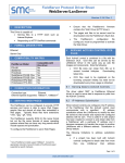
The Sentry Printer Option aids in management of
your gas risk with the ability to print a variety of
complete reports.
Sentry's preformatted reports provide critical information
for analyzing gas exposure and evaluating system reliability. Report selection criteria are user definable. These
reports:
•
•
•
•
Help user make better decisions during a gas leak
Provide history to analyze all exposure events
Substantiate due diligence in complying with regulations
Confirm the reliability of the system.
With optional Sentry printer software, preformatted reports
can be printed via the RS232 port on the Sentry connector
panel. Output is either directly from one controller to a
printer or, via the Sentry Master and Subordinate network
system, from several controllers to one printer.
STATUS REPORT
Status Reports show a snapshot of the gas concentration and alarms. The reporting interval is user programmable from 1 hour to 7 days. The first line indicates the controller ID and date/time. The second
line indicates the sensor number and alarm condition
(“L” for low alarm and “H” for high alarm). The third
line indicates the current concentration and the fourth
line indicates the gas type.
Printer (5301-10)
The Sentry Printer is a modern, high-speed, quiet, ultra
compact, state-of-the-art printer that can operate as either
a serial or parallel output printer.
This printer utilizes thermal paper
and thus no ink! It has minimal
moving parts, easy maintenance
with self-diagnostics, and easy
paper loading with a clamshell design. Standard power for the 530110 is 12-24 VDC. An optional
power supply is available to enable an operator to use 120VAC
power..
5301-10
SPL69207
SPL69205
Serial/Parallel Compact Printer
120V Power Supply
Thermal Paper for Compact Printer
SYSTEM REPORT
The System Report lists all the system parameters
including the software configuration of the system, calibration configuration, printer configuration and configuration for each module: on/off condition, calibration status, relay latching configuration, alarm levels, module
type, the controller channel to which it is connected,
and calibration conditions and factors.
<SYSTEM
ID:A
REPORT>
USER # = 1
12/17
15:08
M5000 VER:4.19
PN 8C
CALIBRATION CONFIGURATION:
LC: OFF
CAL FREQ= 90
-------------------------------<STATUS REPORT>
ID:A STATUS = 01 HOUR 12/17 15:00
1
2
3
4
5
6
7
8
03
04
20.9 20.9 08
08
18
19
H2S COMB OXY OXY COMB COMB COMB COMB
H2S = 20
CAL DUE = 88
DAYS
COMB= 60
CAL DUE = 89
DAYS <SEL>
--------------------------------<STATUS REPORT>
ID:A STATUS = 01 HOUR 12/17 16:00
1L
2
3
4
5
6
7
8
03
04
20.9 20.9 08
09
08
08
H2S COMB OXY OXY COMB COMB COMB COMB
H2S : MIN. CONC. = 05
CHANGE = 03
COMB: MIN. CONC. = 08
CHANGE = 13
--------------------------------<STATUS REPORT>
ID:A STATUS = 01 HOUR 12/17 17:00
1
2
3
4
5
6
7
8
13
04
20.9 20.9 08
09
22
19
H2S COMB OXY OXY COMB COMB COMB COMB
-------------------------------------<STATUS REPORT>
ID:A STATUS = 01 HOUR 12/17 18:00
1H
2
3L
4
5
6
7L
8
23
04
19.5 20.9 08
06
40
19
H2S COMB OXY OXY COMB COMB COMB COMB
DAYS
PRINTER CONFIGURATION:
PRINTER: ON
STATUS = 07 DAYS HIST:YES
MODULE CONFIGURATION :
MODULE 1 IS ON
H2S
LA= 10 NLATCH
HA= 20
FACTOR(S)=
100
MODULE 2 IS ON
CHANNEL=1
150
LATCH
200
COMB CHANNEL 2
DIAGNOSTIC REPORT
The Diagnostic Report lists the critical voltage conditions
for each module and can be selected to print periodically
at intervals from 1 to 90 minutes.
---------------------------------
Sierra Monitor Corp. 1991 Tarob Ct., Milpitas, CA 95035, USA, 408-262-6611, 800-727-4377, FAX: 408-262-9042
Web Site: http://www.sierramonitor.com
E-Mail: [email protected]
© 2009 by Sierra Monitor Corporation
Sentry Printer
PRINTER
KEY EVENT REPORT
When any module reading exceeds a preset minimum
level an Event Report is generated. After the sensor is
above the minimum level, any change greater than a preset change concentration will cause another Event Report to print. The Event Report prints all module numbers and their present reading. This concise record provides information for better decision-making before an
alarm level is reached.
---------------------------------------ID:A <KEY EVENT REPORT>
12/17 14:27
1
2
3
4
5
6
7
8
05
03
23
29
07
02
01
02
---------------------------------------ID:A <KEY EVENT REPORT>
12/17 14:35
1
2
3
4
5
6
7
8
07
03
23
25
08
02
01
02
ACCESSORIES
---------------------------------------ID:A <KEY EVENT REPORT>
12/17 14:37
1L
2
3
4
5L
6
7
8
11
03
23
25
12
02
02
03
---------------------------------------ID:A <KEY EVENT REPORT>
12/17 14:40
1H
2
3
4
5L
6
7
8
21
04
23
24
12
03
09
02
---------------------------------------ID:A <KEY EVENT REPORT>
12/17 14:45
1H
2
3
4
5L
6
7L
8
35
04
22
24
13
03
20
02
---------------------------------------ID:A <KEY EVENT REPORT>
12/17 14:56
1H
2
3
4
5
6
7L
8
The Calibration Report prints automatically upon completion of calibration. The report indicates which gas type
was calibrated, the gas concentration and the planned
frequency of calibration. For each module the report lists
the percent change during calibration, the peak concentration and the zero and span sensor voltages. Module
sensitivity is also checked. Proper sensitivity requires
that the voltage difference obtained in air (1st voltage) and
with span gas (2nd voltage) is sufficient to get adequate
resolution.
---------------------------<CALIBRATION REPORT>
ID:A USER # =0
12/18 10:03
A
A
A
L
S TYPE :
LIB CONC=
L FREQ=
OBAL CALIB:
>MOD
%
P
1
2
>MOD
%
P
1
2
>MOD
L
%
P
1
2
UL
C
EA
ST
ND
UL
C
EA
ST
ND
UL
OW
C
EA
ST
ND
E #
HAN
K C
VO
VO
E #
HAN
K C
VO
VO
E #
SE
HAN
K C
VO
VO
G
O
L
L
G
O
L
L
N
G
O
L
L
=
E
=
NC.
=
TAGE =
TAGE =
=
E
=
NC.
=
TAGE =
TAGE =
=
SIVITY
E
=
NC.
=
TAGE =
TAGE =
The History Report lists the last time each significant
event has occurred. This includes system power interruption, history reset, alarm and concentration information for each sensor, calibration time for each sensor and
an error log. A History Report can be printed each time a
programmed Status Report is printed. These records are
useful in establishing the presence of gas during the period and documenting the company’s due diligence in its
gas monitoring efforts.
---------------------------------------<HISTORY REPORT>
ID:A
USER # =1
12/17 15:08
HISTORY RESET AT: 02/01 10:59
POWER DOWN AT:12/17 13:34
POWER UP
AT:12/17 13:44
MODULE 1
PPM H2S
LOW ALARM 12/13 05:07
HIGH ALARM 12/17 15:07
LOWEST CONC = 00 12/16 10:59
HIGHEST CONC = 23 12/17 15:07
LAST CALIBRATED :02/15 14:33
MODULE 2 %LEL COMB
LOW ALARM 12/10 12:08
HIGH ALARM 00/00 00:00
LOWEST CONC = 00 12/16 11:36
HIGHEST CONC = 45 12/10 12:35
LAST CALIBRATED :02/16 11:35
MODULE 3 %LEL COMB
LOW ALARM 12/10 11:57
HIGH ALARM 12/10 12:20
LOWEST CONC = 00 03/16
CALIBRATION REPORT
G
C
C
G
HISTORY REPORT
COMB
60
90 DAYS
OFF
2
+
6
+
+
01 %FS
1
0.073
0.810
4
+
+
15 %FS
5
1.649
1.395
+
6
+
+
01 %FS
1
0.073
0.816
3
4
10:59
WARM START REPORT
At any time the system is warm started due to a power
failure, a report is generated to show the system software configuration, the result of an internal diagnostic
sequence and the power down and power up date and
times.
SPECIFICATIONS for Printer 5301-10
PRINTING:
Direct Thermal
CHARACTERS per LINE: 16 cpi, 24 cpi, 32 cpi, 42 cpi
CHARACTER SIZE
9x24 dots, 12x24 dots, 16x24 dots,
24x24 dots
RESOLUTION
203 dpi, 8 dots/mm
PRINT WIDTH
2-inch (48 mm)
PRINTING SPEED
50 mm/sec
INTERFACES
Sentry Controller Serial RS232
Sentry Commander Parallel
FieldServer
Serial RS232
DIMENSIONS
3.2 x 3.95 x 2.2 inches (80 x 75 x 55
mm)
PAPER
Thermal Roll 57 mm wide; 40 mm
diameter, spproximately 20m long
POWER
12V-24V DC
OPERATIING TEMP.
32 - 113oF (0-45oC)
Sierra Monitor Corp. 1991 Tarob Ct., Milpitas, CA 95035, USA, 408-262-6611, 800-727-4377, FAX: 408-262-9042
Web Site: http://www.sierramonitor.com
E-Mail: [email protected]
© 2009 by Sierra Monitor Corporation


