1
Automation and Drives - SCE
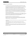
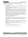
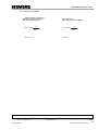
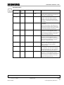
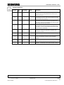
Assignment List:
Symbol:
Start
Stop
Address:
I
1.3
I
1.4
Comment
Button Start
Button Stop
AI_Level_Actual
AI_Level_Setpoint
PEW 128
PEW 130
Analog input for the level sensor
Analog input for the setpoint selection
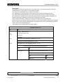
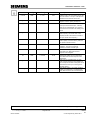
AI_Level_Act_Norm MD 20
AI_Level_Setp_Norm MD 24
M_X1
MD 32
M_Xo
MD 36
M_Xs
MD 28
M_Xu
MD 40
Controller_On
M
10.0
Normalized value for the level
Normalized value for the level setpoint
Intermediate flag half the differential
Intermediate flag high operating point
Intermediate flag switching hysteresis
Intermediate flag low operating point
Flag controller is switched on
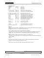
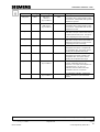
Pump
Display_ON
Pump activation binary
Indication: system is on
A
A
Analog
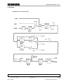
FC1
Two Pos.Controller FC2
0.0
1.0
Subroutine analog value processing
Subroutine two position controller
Exercise:
Create a project with hardware configuration for a CPU314C-2 DP (refer to Module A05) and change
the addresses according to the assignment list shown above.
There, create a program in an FC1 with the following functionality:
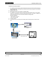
- The analog value for the process variable Level is to be entered, and normalized to the physical
variable "Liter“. The normalized value is made available in MD20 as a floating point number.
Note: If the level is 10 liters, the level sensor returns 0V, for 100 liters 10V.
- The analog value for the setpoint is to be entered, and made available normalized as floating point
number in MD24.
Save FC1.
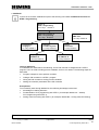
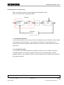
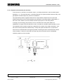
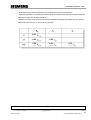
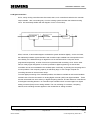
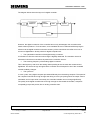
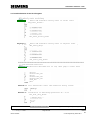
Then, set up the two position controller in an FC2, based on the structogram provided above.
Call FC1 for inputting the setpoint and the actual value.
Save FC2 and call it in OB1. Save OB1 and load the entire station to the PLC.
Preface
Fundamentals
T I A Training Document
Issued: 02/2008
Discontinuous Action Controllerr
Controller Block (S)FB41
Setting the System
Appendix
Page 33 of 64
Module
B3
Control Engineering with STEP 7