1
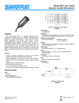
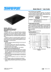
Model SM11 User Guide Dynamic Lavalier Microphone Á ÁÁÁÁÁÁÁÁÁÁÁ Á Á Á Á Á Á Á Á Á Á Á ÁÁÁÁÁÁÁÁÁÁ ÁÁÁÁÁÁÁÁÁÁÁ Á Á Á Á Á Á Á Á Á Á Á ÁÁÁÁÁÁÁÁÁÁÁ ÁÁÁÁÁÁÁÁÁÁÁ ÁÁÁÁÁÁÁÁÁÁÁ ÁÁÁÁÁÁÁÁÁÁÁ ÁÁÁÁÁÁÁÁÁÁÁ ÁÁÁÁÁÁÁÁÁÁÁ ÁÁÁÁÁÁÁÁÁÁÁ GENERAL The Shure Model SM11 is a miniature dynamic lavalier microphone designed for use in television broadcasting (on camera), for sound reinforcement, in certain radio and motion picture applications, and similar uses where a small, professional-quality, microphone is required. The SM11 has an omnidirectional pickup pattern, and its frequency response is optimized for lavalier use. The microphone is supplied with a tie clasp assembly, tie tack assembly, connector belt clip, and zippered carrying/storage bag. An optional kit for mounting the SM11 on various musical instruments is available as Shure Model RK279. Features • Frequency response optimized for lavalier use. Acoustically matches most stand- or desk-mounted microphones • Small and lightweight for unobtrusive, virtually unseen operation • Smooth exterior and recessed grille screen minimize clothing noise • Rugged aluminum case construction • Extremely flexible long-life cable • Two mounting options–tie clasp or tie tack • Convenient, secure belt clip attaches connector to belt or clothing SPECIFICATIONS Type Dynamic Frequency Response 50 to 15,000 Hz (see Figure 1) 2001, Shure Incorporated 27B3077 (AF) TYPICAL FREQUENCY RESPONSE FIGURE 1 Polar Pattern Omnidirectional Impedance Microphone rating impedance is 150 ohms (200 ohms actual) for connection to microphone inputs rated at 19 to 300 ohms Output Level (at 1,000 Hz) Open Circuit Voltage .......... –64 dBV/Pa (0.60 mV) (1 Pa = 94 dB SPL) Polarity Positive pressure on diaphragm produces positive voltage on pin 2 with respect to pin 3 Hum Pickup 35 dB equivalent SPL in a 1 millioersted field Cable Non-detachable, 1.2 m (48 in.), two-conductor, shielded, plastic-covered Connector Professional three-pin audio (XLR). Case Aluminum with gray enamel finish Dimensions See Figure 2 CABLE: 1219 mm (48 in.) 83.5 mm (3 9/32 in.) 38.1 mm (1 1/2 in.) 14.29 mm (9/16 in.) OVERALL DIMENSIONS FIGURE 2 Printed in Mexico Net Weight 7.9 grams (0.28 oz), less cable and connector Certification Conforms to European Union directives, eligible to bear CE marking; meets European Union EMC Immunity Requirements (EN 50082–1: 1992). CARTRIDGE RED CODED TERMINAL YELLOW SHIELD RED CONNECTOR 2 1 3 BLACK INTERNAL CONNECTIONS FIGURE 3 INSTALLATION Tie Clasp Assembly Insert the SM11 in the tie clasp and anchor the cable as shown in Figure 4. Affix the clasp to a tie, shirt, or blouse. Note that the microphone can be swiveled 360° in its holder for left, right, or vertical (“pen clip”) use. clothing. Excess microphone cable can be inserted in the user’s pocket or tucked into the waistband. ARCHITECTS’ SPECIFICATIONS The microphone shall be a moving–coil (dynamic) type with a frequency response of 50 to 15,000 Hz. The microphone shall have an omnidirectional polar characteristic. The microphone shall be low impedance with a rated impedance of 150 ohms for connection to microphone inputs rated at 19 to 300 ohms. The microphone output shall be –64 dB where 0 dB = 1 milliwatt per 10 microbars. The microphone shall be a lavalier type, and shall be provided with a 1.2m (48 in.) non–detachable, two–conductor, shielded cable with a professional, three–pin audio connector designed to mate with Cannon XL series, Switchcraft A3 (Q.G.) series or equivalent connectors. The microphone shall also be provided with a tie clasp assembly, tie tack assembly, connector belt clip, and carrying/storage bag. The overall dimensions of the microphone shall be 33.5 mm (1 – 5/16 in.) in length and 14.7 mm (9/16 in.) in diameter. The microphone shall be the Shure Model SM11 or equivalent. ACCESSORIES AND REPLACEMENT PARTS The following furnished accessories and replacement parts can be ordered through your Authorized Shure Professional Products Dealer or from Shure Incorporated. Tie Clasp Assembly . . . . . . . . . . . . . . . . . . . . . . . RK203TC Tie Tack Assembly . . . . . . . . . . . . . . . . . . . . . . . . . 90A2384 Connector Belt Clip . . . . . . . . . . . . . . . . . . . . . . . . RK200BC Carrying/Storage Bag . . . . . . . . . . . . . . . . . . . . . . . . . 26A13 Cartridge . . . . . . . . . . . . . . . . . . . . . . . . . . . . . . . . . . . . . . R99 Cable . . . . . . . . . . . . . . . . . . . . . . . . . . . . . . . . . . . . . . . . . . C91 Instrument Mounting Kit . . . . . . . . . . . . . . . . . . . . . . . RK279 For additional service or parts information, please contact Shure’s Service Department at 1–800–516–2525. Outside the United States, please contact your authorized Shure Service Center. CABLE ANCHORING FIGURE 4 Tie Tack Assembly Remove the clutch from the tie tack assembly and insert the tie tack holder in the tie (or through the tie and shirt if desired). Affix the clutch to the pin of the tie tack holder. Insert the SM11 in the tie tack holder. Connector and Belt Clip With the SM11 installed in one of the assemblies described above, insert the connector in the connector belt clip and fasten the belt clip to the user’s belt, waistband or other SHURE Incorporated Web Address: http://www.shure.com 222 Hartrey Avenue, Evanston, IL 60202–3696, U.S.A. Phone: 847-866–2200 Fax: 847-866-2279 In Europe, Phone: 49-7131-72140 Fax: 49-7131-721414 In Asia, Phone: 852-2893-4290 Fax: 852-2893-4055 Elsewhere, Phone: 847-866–2200 Fax: 847-866-2585