1
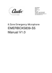
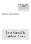
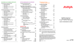
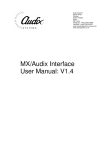
Audix Systems,
Station Road,
Wenden,
Saffron Walden,
Essex,
CB11 4LG.
Telephone: +44(0)1799 540888
Facsimile: +44(0)1799 541618
www.tycosafetyproducts-europe.com
www.audixsystems.co.uk
Emergency/Fireman’s Microphone
EMERBOX5839
Manual V1.1
EMERBOX5839 User Manual
Revision History
Version
1.0
1.1
Modifications
Original issue.
Re-arrange sections and add connection details
Date
12/12/02
30/08/05
© Copyright Audix Systems. 2005
DISCLAIMER
This manual contains information that is correct to the best of Audix Systems
knowledge. It is intended to be a guide and should be used as such. It
should not be considered as a sole source of technical instruction, replacing
good technical judgement, since all possible situations cannot be anticipated.
If there are any doubts as to exact installation, configuration and/or use, call
Audix Systems at +44 (0)1799 540888
ACKNOWLEDGEMENTS
All trademarks are recognised
Technical Support
In the unlikely event of you having problems with your EMERBOX5839 please
contact our Technical Support.
Audix Systems
Station Road
Wenden
Saffron Walden
CB11 4LG
Tel +44 (0)1799 540888
Fax +44 (0)1799 541618
Page 2 of 16
21025 EMERBOX5839 V1.1-resaved.doc
EMERBOX5839 User Manual
Table of contents
Revision History ...........................................................................................2
Technical Support ........................................................................................2
Table of contents..........................................................................................3
EMERBOX5839 Overview............................................................................4
Product Description ......................................................................................5
Operating instructions ..................................................................................5
Specifications ...............................................................................................6
EMERBOX5839 as part of a VA system. .....................................................7
Installation and connection to VA PA system ...............................................7
General installation notes .........................................................................7
Cable requirements ..................................................................................8
Summary of installation procedure. ..........................................................8
Making connections ..................................................................................9
Connector Details .....................................................................................9
Setting Up...................................................................................................10
Jumper settings ......................................................................................10
D718 Trim Pot Settings...........................................................................10
Microphone Internal Connections ...........................................................11
How the switch contacts are monitored......................................................12
Monitoring resistors ................................................................................12
Safety Considerations. ...............................................................................13
Technical description of D718 microphone preamplifier.............................14
D718 Mic Pre Amp component identification..............................................16
Page 3 of 16
21025 EMERBOX5839 V1.1-resaved.doc
EMERBOX5839 User Manual
EMERBOX5839 Overview
The microphone comprises;
• Hi Quality Shure557B Fist Microphone with PTT (Press To Talk Button)
• Speak indicator (Green)
• Power indication
• Both Microphone and Contact Monitored to VA Rack
• Can be used as the VA system Bypass Microphone
• Rugged Steel Enclosure
• Built in Microphone pre-amplifier (D718)
EMERBOX5839
Page 4 of 16
21025 EMERBOX5839 V1.1-resaved.doc
EMERBOX5839 User Manual
Product Description
The EMERBOX5839 Emergency/ Fireman’s Microphone comprises a handheld fist type microphone together with a DC powered microphone
preamplifier housed within a wall mounted enclosure.
The microphone has a single button (PTT) which is connected to monitoring
resistors located within the EMERBOX5839. When connected to an Audix
MSL1000 this allow the PTT connections to be monitored for open circuit and
short circuit failure.
The preamp is an Audix D718 with circuitry to inject 20kHz tone into the mic
circuit for complete signal path surveillance by the host VA system and to
allow the mic itself to be monitored for open circuit and short circuit failure.
When the PTT (Press To Talk) button is pressed a pre programmed,
individual or grouped output (speaker zones) request is made to the host VA
system.
Operating instructions
To make a LIVE broadcast announcement
•
To make an announcement the user is to press and hold the Speak button.
Until this point the announcer has had no effect on the PA system.
•
A rapidly flashing green LED by the Speak button, indicates that the preannounce chime is active and the announcer should wait until this green
LED stays solidly on. This is the Speak-now indication.
•
Whilst holding the Speak button, the announcer should then talk steadily
and clearly into the microphone with their mouth about 10 to 20 cm. from
the microphone head.
•
Whilst holding the Speak button, the announcer should then talk steadily
and clearly into the microphone with their top lip against the rubber lip
guard. The microphone panel has a pre-amplifier which utilises a
compressor/limiter circuit. This boosts a quiet voice and limits a loud voice
to enable consistent loudness of broadcasts
•
Release the PTT.
Page 5 of 16
21025 EMERBOX5839 V1.1-resaved.doc
EMERBOX5839 User Manual
Specifications
EMERBOX Enclosure Dimensions (HxWxD)mm
Weight, excluding cables
Power supply voltage range
Supply current (typical)
300 x 300 x 210
5 kg.
15 – 30V DC
55mA @ 24V
Audio output nominal
Audio output max.
Output impedance
Load impedance
Distortion T.H.D.
Signal to Noise ratio
0dBu
+10dBu
< 50 ohms
> 600ohms
< 0.05%
Pre-announcement chimes
2 or 3 tone
Microphone gain trim range
Preset
Surveillance tone Frequency
Surveillance tone Level
Surveillance tone stability
20kHz
Adjustable
o
100ppm/ C
Max Operating Distance from System Rack
Operating temperature range
Max Humidity
EMC operating environment
(As defined by EN50081-1, EN50082-1)
Manufactured to Safety Standard
Microphone Type
Microphone Technology
Microphone Frequency Response
Microphone Output Level (@1kHz)
Microphone Impedance
Microphone Hum Sensitivity
Microphone Operating Temperature Range
Microphone PTT Switch Type
Microphone Cable
Microphone Case
Microphone Weight
500m
o
0 – 40 C
85% non-condensing
Domestic, Commercial,
Light Industrial.
EN60065:1998
Shure 577B
Dynamic, noise-cancelling
100Hz – 5kHz (+/- 3dB)
-46.0 dB (5.0mV)
0dB = 1volt per 100 micro bars
-66.0 dBV/Pa (0.5mV)
1Pa =94dB SPL
175 ohm
Equivalent to 32dB SPL in 1
millioersted field
-40 to +74OC
Double-pole, single-throw, leaftype, push-to-talk
Non-detachable 1.8m,
neoprene-jacketed coil cord,
four conductor
Two tone grey, high-impact
ARMO-DUR
330g
Page 6 of 16
21025 EMERBOX5839 V1.1-resaved.doc
EMERBOX5839 User Manual
EMERBOX5839 as part of a VA system.
The following Diagram shows how the EMERBOX5839 would typically be
connected into an Audix Alpha based Voice Alarm system.
Installation and connection to VA PA system
General installation notes
Install the EMERBOX5839S5 enclosure in a suitable location, which must be
fully compatible with the "Safety Considerations" section of this manual.
The unit is heavy so must be installed with adequate fixings.
Please observe all installation requirements for standards compliance.
Turn off power sources of the system rack whilst making connections to the
system.
Care should be taken when installing microphone cabling with respect to other
power cables and systems likely to cause interference e.g. Mains cabling,
Motors etc.
Page 7 of 16
21025 EMERBOX5839 V1.1-resaved.doc
EMERBOX5839 User Manual
Cable requirements
The unit is connected to the PA system via a Fire Rated Four pair 0.75mm2
cable.
Pair 1: The unit is powered from a nominal 24V D.C. supply derived from.
Pair 2: Audio output from the unit is at balanced line level audio 0dBu nominal.
Pair 3: Monitored PTT output and 0V return
Pair 4: Bypass PTT control out + spare connections.
Each pair should be individually screened, with a common overall screen
connected to earth. Foil screened cables with solid copper drain-wire are
preferred.
A suitable Fire Rated cable must be used if the unit forms part of a VA
system.
Non-standard and specially customised units may have extra features
supported on additional cables and connections on the spare terminals
indicated. These functions will generally be described in the specific system
documentation
Audix Systems can offer advice, based on previous experience as to suitable
cable types and maximum cable lengths.
Warning: Upon first connection of the EMERBOX5839 to a system, the initial
setting of the 20kHz surveillance tone is set at the factory and may need to be
adjusted during system commissioning.
Summary of installation procedure.
Remove the 8 M5 screws that hold the door and the internal pre-amp panel
assembly, remove the door and panel, and the fix the empty box in the
required location.
Terminate cable screens to the earth stud, on the base-plate of the wall-box.
Terminate the cables onto the pre-amp/front panel assembly.
Set up any switches and jumpers Control PCB and test the system.
Refit the pre-amp/front panel assembly and the door of the wall-box.
Page 8 of 16
21025 EMERBOX5839 V1.1-resaved.doc
EMERBOX5839 User Manual
Making connections
To meet EMC requirements short connections are required between the cable
screens and enclosure metal work.
The figure below shows the recommended method of terminating the screens,
which can only be achieved if the cable entry point is located close to the
earth stud on the base plate within the enclosure.
The length of the cable inners should be 250 - 300mm long in order to allow
the pre-amp panel assembly to be wired after fixing the
enclosure.
Connector Details
Connections are located on the rear of the EMERBOX5839 front panel
assembly.
Customised units may have extra features supported on the spare terminals
indicated. These functions will generally be described in the specific system
documentation
Page 9 of 16
21025 EMERBOX5839 V1.1-resaved.doc
EMERBOX5839 User Manual
Setting Up.
There are a number of pre-set controls on the D718 Pre-amp PCB that must
be set during system commissioning.
The function of these controls is shown in the list below.
Use the Channel Gain Control on the PA System to adjust the volume of the
microphone. Do not adjust the “VR5 mic gain control” on D718 which has
been factory set to match the characteristics of the microphone.
Trimpot VR3 should be used to adjust the chime volume after the mic volume
has set on the PA system.
The jumper J1 should be set to select the required chime.
To turn the chime off completely fit J2.
Jumper settings
Normal settings for EMERBOX5839 are shown highlighted.
J1
J2
J3
J4
J5
J6
Omit
Fit
Omit
Fit
Omit
Fit
Omit
Fit
Omit
Fit
Omit
Fit
2 tone chime
3 tone chime
Enable Chime
Disable Chime
Ptt Operation, Active Low (Fit J5)
Ptt Operation, Active High (Omit J5)
Normal Operation
Permanently Enable Pre Amplifier
Ptt Operation, Active High (Fit J3)
Ptt Operation, Active Low (Omit J3)
Power Off
Power On
D718 Trim Pot Settings
VR1 – Distortion Trim
VR2 – Set 20kHz Level
VR3 – Set Chime Level
VR4 – Set Threshold for Limiter
VR5 – Microphone Gain
VR6 – Set Chime Pitch
VR7 – Output Gain
(Do Not Adjust)
(Do Not Adjust)
(Do Not Adjust)
(Do Not Adjust)
Page 10 of 16
21025 EMERBOX5839 V1.1-resaved.doc
EMERBOX5839 User Manual
Microphone Internal Connections
The D577 microphone, as supplied from Shure has a shorting switch contact
across the mic coil. this shorting contact must be disconnected in order to
allow the 20kHz surveillance to function.
If a new mic is fitted, as a replacement the modification is described below.
The green wire from the mic cartridge should be unsoldered from the wiper
terminal of the switch and connected to the same terminal as the other green
wire
Note that the diagram shows internal connections of an un-modified
microphone.
Page 11 of 16
21025 EMERBOX5839 V1.1-resaved.doc
EMERBOX5839 User Manual
How the switch contacts are monitored.
The PTT switch line between the microphone and the MSL is monitored for
open circuit and short circuit failure.
Each input has 4 states, defined by voltage levels: o/c fault, s/c fault, active,
and inactive.
The Microphone PTT is fitted with the specified monitoring resistors located
within the EMERBOX5839
Failure of any or the power rails within the unit will cause an active low signal
on the ‘common fault’ output from the unit.
Monitoring resistors
Specified end of line resistors, as supplied fitted within the EMERBOX5839
R in series with contacts: 910Ω 1% 100ppm 0.3W metal film
R in parallel with contacts: 3KΩ 1% 100ppm 0.3W metal film
Figure 3. MSL Wiring Details
This gives the following resistance readings:
Switch Closed state circuit resistance
Switch Open state circuit resistance
kΩ)
Control Line Short Circuit
Control Line Open Circuit
= 910 Ω.
= 3.91 kΩ ( 910Ω +3.0
=0Ω
=∞Ω
Where the Fireman’s microphone is connected into the MSL1000 unit the
input must be configured to be non-latching.
Page 12 of 16
21025 EMERBOX5839 V1.1-resaved.doc
EMERBOX5839 User Manual
Safety Considerations.
Review the following safety precautions to avoid injury and prevent damage to
the product. The product should only be used as specified.
The EMERBOX5839 should be operated from a suitable DC supply of
nominally 24V. Use only the correct power source, which must contain current
overload protection to protect the wiring between the system and the
EMERBOX5839.
Do not disconnect the cable from the product whilst the Voice Alarm system is
powered.
Do not operate in wet or damp conditions or expose to dripping or splashing.
Do not operate in an Explosive Atmosphere
This product may be incorporated into a Monitored Voice Alarm system. If so,
to tamper with any of the setting of the EMERBOX5839 unit may cause a
Fault Condition warning on the Voice Alarm control unit. In these
circumstances the restoration of normal operation of the system may not be
possible without access to the Main Voice Alarm Equipment by qualified
personnel.
Page 13 of 16
21025 EMERBOX5839 V1.1-resaved.doc
EMERBOX5839 User Manual
Technical description of D718 microphone preamplifier
The D718 is a low noise remote microphone amplifier board with balanced
input and built in AGC/compressor maintaining maximum intelligibility. The
nominal compression ratio is 5 to 1 , but increases towards the higher level
end of the range . The underlying AGC operates slowly with an attack time
of around 3s ( gain control is mostly transferred from the compressor) and
release time of around 10s, but has a fast recovery (approx. 1s rate ) which
operates if the output level falls below 10 to 15dB of its current nominal
value for longer than 1.5s. The AGC recovery rate of around 10s is reestablished when the signal level recovers to within the 15dB range of the
nominal output level.
The compressor effectively operates "over the top" of the AGC to reduce the
dynamic range of the gain adjusted signal. The reason for this approach (
rather than just having a simple compressor is to reduce the amount of
crackle and distortion of the signal to improve overall intelligibility of the
speech signal. The compressor operates normally with an attack time of
around 10ms and a release time of 200ms which gives good dynamic range
control with minimal attack distortion. To control the initial attack and any
subsequent large excursions of the signal, the attack time speeds to around
1ms for any instantaneous input increase of greater than about 4dB above
the current output level. To help prevent the compressor modulating the noise
during short pauses in the input speech signal (i.e. unwanted "breathing") the
compressor release time is increased greatly if the output level falls to
below 10 to 15dB of the current output level. Normal control is re-established
when the output level rises above this level.
The board also incorporates a 20kHz surveillance oscillator which injects tone
directly into the microphone input for use in the rest of the PA system, but
which will also detect (absence of tone) a short or open circuit fault at the
microphone. The 20kHz generator is arranged to inverse-track the gain
control applied by the compressor so that an approximately constant level of
surveillance tone is always available at the output.
A chime circuit ( ding-dong ) may be optionally triggered from the control input
(e.g. press to talk switch ) and if used gives a logic level output which is
intended to flash an led during the chime and switch it continuously on when
the microphone is enabled.
Finally, the microphone is 'live' all of the time so as to enable continuous
surveillance of all of the circuitry in the system. However, to avoid audible
signal pick-up from the microphone in its non-active state, additional gain
reduction is applied in this state which is switched out when the microphone
is required.
A digitally synthesized 20kHz monitor tone for the Audix Systems FMS is
injected directly at the microphone head, with innovative circuitry able to
detect open or short circuit failure of the microphone.
Page 14 of 16
21025 EMERBOX5839 V1.1-resaved.doc
EMERBOX5839 User Manual
The D718 microphone pre amplifier features a choice of 2 built in pre
announcement chime signals. There is independent adjustment for the chime
volume.
Due to continued development, Audix Systems reserves the right to change
any of the operational features of the EMERBOX5839 described in this
document.
Page 15 of 16
21025 EMERBOX5839 V1.1-resaved.doc
EMERBOX5839 User Manual
D718 Mic Pre Amp component identification
Page 16 of 16
21025 EMERBOX5839 V1.1-resaved.doc