1
SHINDAIWA OWNER’S/OPERATOR'S MANUAL
T272 TRIMMER
T272X TRIMMER
T272
T272X
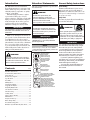
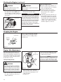
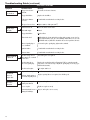
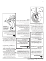
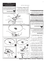
WARNING!
Minimize the risk of injury to
yourself and others! Read this
manual and familiarize yourself
with the contents. Always wear
eye and hearing protection when
operating this unit.
Part Number 81647 Rev 1/07
Introduction
Attention Statements
Throughout this manual are special “attenThe Shindaiwa 272-series hand-held
Power Equipment has been designed and tion statements”.
built to deliver superior performance and
reliability without compromise to quality,
WARNING!
comfort, or durability.
Shindaiwa high performance engines
A statement preceded by the
represent the leading edge of 2-cycle
triangular attention symbol and
engine technology, delivering exceptionally the word “WARNING” contains inforhigh power from remarkably low displacemation that should be acted
ment and weight. As an owner/operator,
upon to prevent serious bodily injury.
you’ll soon discover for yourself why
Shindaiwa is simply in a class by itself!
CAUTION!
IMPORTANT!
A statement preceded by the word
The information contained in this manual
“CAUTION” contains information that
describes units available at the time of
should be acted upon to prevent mepublication.
chanical damage.
While every attempt has been made to
give you the very latest information about
your Shindaiwa product, there may be
some differences between your 272-series
unit and what is described here. Shindaiwa
Inc. reserves the right to make changes
to products without prior notification, and
without obligation to make alterations to
units previously manufactured.
WARNING!
The engine exhaust from this product
contains chemicals known to the State
of California to cause cancer, birth defects or other reproductive harm.
Contents
PAGE
Attention Statements...................................... 2
General Safety Instructions........................... 2
Safety Labels.................................................... 4
Product Description........................................ 4
Specifications................................................... 5
Assembly.......................................................... 5
Mixing Fuel..................................................... 9
Starting the Engine......................................... 9
Stopping the Engine..................................... 10
Adjusting Engine Idle................................... 10
Check Unit Condition................................... 11
Shoulder Strap............................................... 11
Cutting Grass................................................. 11
Using a Bade (T272X).................................. 12
Maintenance.................................................. 13
Long Term Storage....................................... 15
Blade Sharpening.......................................... 15
Troubleshooting guide................................. 16
Emission System Warranty Statement....... 1 9
IMPORTANT!
A statement preceded by the word
“IMPORTANT” is one that possesses
special significance.
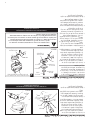
General Safety Instructions
Work Safely
Trimmers and brushcutters operate at very
high speeds and can do serious damage or
injury if they are misused or abused. Never allow a person without training or instruction
to operate your unit!
Stay Alert
You must be physically and mentally fit to
operate this unit safely.
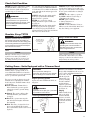
WARNING!
�
DO NOT OPE
IF YOU ARE
UNDER THE
ALCOHOL, D
MEDICATION
�
�
�
Never operate power equipment of
any kind if you are tired or if you are
under the influence of alcohol, drugs,
medication or any other substance that
could affect your ability or judgment.
IMPORTANT!
The operational procedures described in
NOTE:
this manual are intended to help you get
A statement preceded by the word “NOTE”
the most from your unit, and to protect
contains information that is handy to know and you and others from harm. These procemay make your job easier.
dures are guidelines for safe operation
under most conditions, and are not inRead and follow this
tended to replace any safety rules and/or
operators manual.
Failure to do so could
laws that may be in force in your area.
result in serious injury.
If you have questions regarding your
Wear eye and hearing
272-series unit, or if you do not understand
protection at all times
during the operation
something in this manual, your Shindaiwa
of this unit.
dealer will be glad to assist you.
Keep bystanders
You may also contact Shindaiwa, Inc.
at least 50 feet (15 m)
at the address printed on the back of
away during operation.
this manual.
Beware of thrown or
ricocheted objects.
Do not operate this unit with a
blade unless the unit is equipped
with a Shindaiwa-approved
handlebar or barrier.
Always wear a harness when
operating this unit with a blade.
A harness is also recommended
when using trimmer line.
If unit is used as a brushcutter,
beware of blade thrust. A jammed
blade can cause the unit to jerk
suddenly and may cause the
operator to lose control of the unit.
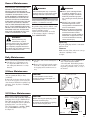
General Safety Instructions
WARNING!
Never make unauthorized attachment
installations.
WARNING!
The Properly Equipped Operator
Wear close-fitting clothing to
protect legs and arms. Gloves
offer added protection and are
strongly recommended. Do
not wear clothing or jewelry
that could get caught in machinery or underbrush.
NEVER wear
shorts!
Wear hearing protection devices and a
Always wear eye
broad-brimmed hat or helmet.
protection such as goggles or
safety glasses.
Always wear a shoulder strap
or a harness when operating
a unit equipped with a blade.
Use Good Judgment
ALWAYS wear eye protection to
shield against thrown objects.
NEVER operate the engine when
transporting the unit.
NEVER operate the engine indoors!
Make sure there is always good ventilation. Fumes from engine exhaust
can cause serious injury or death.
ALWAYS clear your work area of
trash or hidden debris that could
be thrown back at you or toward a
bystander.
ALWAYS use the proper cutting tool
for the job.
ALWAYS stop the unit immediately if
it suddenly begins to vibrate or shake.
Inspect for broken, missing or improperly installed parts or attachments.
NEVER extend trimming line beyond
the length specified for your unit.
ALWAYS keep the unit as clean as
practical. Keep it free of loose vegetation, mud, etc.
ALWAYS hold the unit firmly with both
hands when cutting or trimming, and
maintain control at all times.
ALWAYS keep the handles clean.
ALWAYS disconnect the spark plug
wire before performing any
maintenance work.
ALWAYS, if a blade should bind fast
in a cut, shut off the engine immediately. Push the branch or tree to ease
the bind and free the blade.
Always operate with both
hands firmly gripping the
unit.
When operating with a blade, make
sure the handle is positioned to provide you with maximum protection
from contacting the blade.
Keep a proper
footing and do not
overreach—maintain your balance
at all times during
operation.
Wear appropriate footwear (nonskid boots or shoes): do not wear
open-toed shoes or sandals. Never
work barefooted!
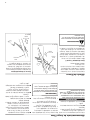
Figure 1
Keep away from the rotating
trimming line or blade at all
times, and never lift a moving
attachment above waist-high.
Always make sure
the appropriate cutting
attachment shield is
correctly installed.
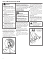
Be Aware of the Working Environment
Make sure bystanders
or observers outside the
50-foot “danger zone”
wear eye protection.
Avoid long-term operation
in very hot or very cold
weather.
Reduce the risk of
bystanders being struck
by flying debris. Make
sure no one is within 50
feet (15 meters)—that’s
about 16 paces—of an
operating attachment.
Be extremely careful of
slippery terrain, especially
during rainy weather.
50
FEET
If contact is made with a
hard object, stop the engine
and inspect the cutting attachment for damage.
Be constantly alert for objects and debris that
could be thrown either from the rotating cutting
attachment or bounced from a hard surface.
Figure 2
Beware of a coasting blade when brushcutting or
edging. A coasting blade can injure while it continues to spin after the throttle trigger is released
or after the engine is stopped.
When operating in rocky terrain or near electric
wires or fences, use extreme caution to avoid
contacting such items with the cutting attachment.
Safety Labels
T272
POSITION HANDLE
FORWARD OF THIS LINE
This label indicates the minimum
distance between front handle and
rear grip per ANSI B175.3.
IMPORTANT!
Safety and Operation Information
Labels: Make sure all information labels are undamaged and
readable. Immediately replace
damaged or missing information
labels. New labels are available from your local authorized
Shindaiwa dealer.
T272X
Figure 3
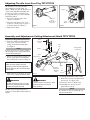
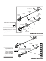
Product Description
T272 Grass Trimmer
Ignition
Switch
Handle
Spark Plug
Grip
Outer Tube
Throttle
Trigger
Fuel
Tank
Gearcase
Cutting
Attachment Shield
T272X Grass Trimmer
Spark Plug
Cylinder
Ignition Cover
Switch
Trimmer Head
Fuel
Tank
Handle
Gearcase
Outer Tube
Cutting
Attachment Shield
Figure 4
Trimmer Head
Barrier Bar
Throttle
Trigger
Using the accompanying illustrations as
a guide, familiarize yourself with your
unit and its various components. Understanding your unit helps ensure top
performance, long service life, and safer
operation.
WARNING!
Do not make unauthorized modifications or alterations to either of these
units or their components.
Specifications T272X/C272
Engine Code.................................................................S272E Engine
Dry weight, T272
(less attachment)................................................6.7kg/14.7 pounds
Dry weight, T272X
(less attachment)................................................6.7kg/14.8 pounds
Type..........................................2-cycle, vertical cylinder, air cooled
Bore x Stroke..................................34 mm x 30 mm/1.3 in. x 1.2 in.
Displacement...........................................................27.2cc/1.7 cu. in.
Maximum Power Output.............................................1.1 kw/1.4 hp
Operating rpm Range...................................4,500-9,000 rpm (min-1)
Transmission Type.............................Automatic centrifugal clutch
through bevel gears
Fuel/Oil Ratio....................................50:1 with ISO-L-EGD or JASO
FC class 2-cycle mixing oil*
Fuel Tank Capacity.............................................670ml/22.6 ounces
Carburetion...................................................Walbro diaphragm-type
Ignition..................................Fully electronic, transistor controlled
Spark Plug.................................................................Champion CJ8Y
Air Cleaner Type....................................Non-reversible heavy-duty
filter element
Starting Method.......................................................................Recoil
Stopping Method................................Slide switch, grounding type
Handle.................................................................Loop handle (T272)
Loop handle with barrier bar (T272X)
EPA Emission Compliance Period**...........................Category A
* Shindaiwa One meets or exceeds these specifications and is recommended
for all Shindaiwa Products
** The EPA emission compliance referred to on the emission compliance label located on the engine, indicates the number of operating hours for which the engine
has been shown to meet Federal emission requirements. Category C = 50 hours
(Moderate), B = 125 hours (Intermediate) and A = 300 hours (Extended).
Specifications are subject to change without notice.
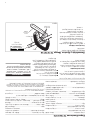
This unit comes fully assembled with the
exception of the cutting attachment shield
and cutting attachment.
n Engine and shaft assembly
Prior to Assembly
n Kit containing cutting attachment shield
bracket and hardware, this owner's/
opertor's manual and tool kit for routine
maintenance. Tool kits vary by model
and may include a hex wrench set,
spark plug/screwdriver combination
wrench and a spanner.
Before assembling, make sure you have all
the components required for a complete
unit and inspect unit and components for
any damage.
n Cutting attachment shield
n Cutting attachment
IMPORTANT!
The terms “left,” “left-hand,” and “LH”:
“right,” “right-hand,” and “RH”; “front” and
“rear” refer to directions as viewed by the
operator during normal operation of this
product.
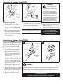
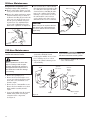
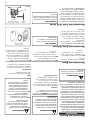
Assembly and Adjustments Handle T272/T272X
Handle
The handle is attached to the outer tube
on the T272/T272X.
To Adjust the Handle.
Handle Positioning Label
1. Loosen the 4 socket-head capscrews on
the handle. See Figure 5.
T272X Shown
2. Position the handle forward of the
Handle Positioning Label at the best
position for operator comfort (usually
about 10 inches ahead of the throttle
housing).
3. Secure the handle by alternately tightening the four socket-head cap screws
in a diagonal or “criss-cross” fashion.
Outer Tube
Barrier
Bar
4 Socket-head Capscrews
Figure 5
Adjusting Throttle Level Free Play T272/T272X
The throttle lever free play should be
approximately 9/32 inch (7mm). See
Figure 7. Make sure that the throttle lever
operates smoothly without binding. If it
becomes necessary to adjust the lever
free play, follow the procedures and illustrations that follow.
1. Loosen the lock nut on the cable
adjuster. See Figure 6.
2. Turn the cable adjuster in or out as
required to obtain proper free play of
9/32 inch (7mm). See Figure 7.
Locknut
9/32 inch
(7 mm)
Throttle Lever
Free Play
Cable
Adjuster
Figure 7
Figure 6
3. Tighten the locknut.
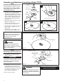
Assembly and Adjustments Cutting Attachment Shield T272/T272X
Install the Cutting Attachment Shield
SocketHead Cap
Screw
1. Insert the cutting attachment shield
between the outer tube and the
cutting attachment mounting plate.
See Figure 8.
Outer
Tube
NOTE:
It may be necessary to loosen the retaining
nut and clamp screw to adjust cutting attachment shield mounting plate.
2. Fit the two shims and the bracket over
the outer tube and loosely install the
four socket-head screws. See Figure 8.
Cutting Attachment Shield
Bracket
Shim
Clamp Screw
Nuts
CAUTION!
Line Cutter
Make sure the clamp screw and
retaining nut are securely tightened
before tightening the four socket head
cap screws.
3. Tighten the four socket-head cap screws
to secure the cutting attachment shield.
WARNING!
NEVER operate the T272 or T272X
without the cutting attachment shield
installed and tightly secured!
The line cutter can be positioned in 2
positions to obtain different line length for
cutting.
Shim
Retaining
Nut 1025
Cutting
Attachment
Mounting
Plate
Figure 8
Hex
Screws
Figure 8A
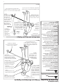
To Change Position of Line Cutter
WARNING!
The line cutter is very sharp. Wear
gloves to protect your hands
when handling.
1. Remove the 2 hex screws with a 4mm
hex wrench. See Figure 12A.
2. Rotate line cutter. See Figure 12A.
3. Reinstall the two hex screws and
tighten them securely.
NOTE:
Be careful to not lose the 2 nuts in the cutting attachment shield.
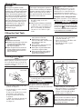
Installing a Trimmer Head T272
WARNING!
Retaining
Plug
A standard grass trimmer with a loop handle
should NEVER be operated with
blade-type attachments. For blade
use the trimmer must be fitted
with a bicycle-type handlebar or a
barrier bar that is located in front
of the operator to reduce the risk
of the operator from coming in
contact with the cutting attachment
(per ANSI B175.3). When using
a blade, the unit must also be
equipped with a harness or strap.
Holder
Output
shaft
Hex Wrench
Figure 9
Install the Trimmer Head.
1. Turn the trimmer over so that the
gearcase output shaft faces UP.
2. Remove and discard the black plastic
protective cap from the output shaft.
See Figure 9.
3. Rotate the holder until the hole in the
holder aligns with the notch on the
gearcase. Use the long end of the hex
wrench to lock the holder and output
shaft. See Figure 10.
Figure 10
4. While holding the hex wrench, thread
the trimmer head onto the output shaft,
turning counter-clockwise. Using hand
pressure only, tighten the trimmer
head firmly on the output shaft.
IMPORTANT!
The trimmer head has a left-hand thread. For
removal turn the trimmer head clockwise.
Installing a Trimmer Head T272X
NOTE:
A
The T272X is shipped with Holder A, the blade retainer (safety clip), Holder B, shaft bolt, and bolt
guard installed. The shaft bolt is a LEFT-HAND
thread. Remove it by turning CLOCKWISE!
1. With the gearcase output shaft facing
up, rotate the gearshaft and holder A
until the hole in holder A aligns with
the matching hole in the gearcase
flange, and then lock the holder to the
gearcase by inserting the long end of
the hex wrench through both holes.
See Figure 11-A.
2. Using the combination spark plug/
screwdriver wrench, remove the shaft
bolt, bolt guard, holder B and the safety
clip. (The bolt guard, shaft bolt and
safety clip are not used with a trimmer
head). See Figure 11-A.
3. Install Holder B on the gearcase shaft.
The splined hole on Holder B must
engage with the gearcase shaft.
4. Using the hex wrench to secure Holder
A , install and hand-tighten the trimmer
head (counter-clockwise to install).
See Figure 11-B.
5. Remove the hex wrench from the
gearcase and holder.
Shaft Bolt
(not used)
Bolt Guard
(not used)
5. Remove the hex wrench.
6. Adjust the trimmer line length to reach
no further than the line
cutter on the cutting attachment shield.
Trim to the correct length if necessary.
The T272 should now be
completely assembled and ready for
use with a trimmer head.
B
Hand-tighten Trimmer Head (counterclockwise to install)
Holder B
Safety Clip
(not used)
Holder A
35007
Gearcase
Shaft
35008
Hex Wrench
Figure 11
WARNING!
A standard grass trimmer unit with loop handle should NEVER be operated with
blade-type attachments. For blade use, the trimmer must be fitted with a bicycle-type
handlebar or barrier bar that is located in front of the operator to reduce the risk of the
operator coming in contact with the cutting attachment. (Per ANSI B175.3). When using a blade, the unit must also be equipped with a harness or strap.
The T272X should now be
completely assembled and ready for use with a trimmer head.
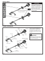
Assembly and Adjustments Installing a Blade T272X
NOTE:
The T272X is shipped with Holder “A,” the
safety clip, Holder “B,” shaft bolt, and bolt
guard installed. The shaft bolt is a LEFTHAND THREAD AND IS REMOVED IN A
CLOCKWISE ROTATION!
1. With the gearcase output shaft facing
up, rotate the gearshaft and holder
"A" until the hole in holder "A" aligns
with the matching hole in the gearcase
flange, and then lock the holder to the
gearcase by inserting the long end of
the hex wrench through both holes.
See Figure 12.
2. Remove the shaft bolt, bolt guard and
holder B. See Figure 12.
3. Slide the safety clip off center on the
gearcase shaft. See Figure 12-A.
4. Slide the blade over the safety clip and
onto the flange on Holder “A.” See
Figure 12-B
5. Lock the blade on the shaft by centering the safety clip. See Figure 12-C.
Shaft Bolt
A
Bolt Guard
Holder “B”
Safety Clip
Gearcase
Shaft
Holder
“A”
35011
35010
Hex
Wrench
Slide the safety clip off-center
C
B
Slip the blade in place
Center the safety clip
35012
35013
Figure 12
CAUTION!
Install the blade so its printed surface
is visible to the operator when the
brushcutter is in the normal
operating position.
35014
WARNING!
The blade must fit flat against the
holder flange. The blade mounting
hole must be centered over the raised
boss on blade holder A.
Blade
Figure 13
NOTE:
When installing certain blades, it may be necessary to temporarily remove the safety clip.
Tighten the assembly
Combination Spark
Plug/Screwdriver
Wrench
6. Install Holder “B” on the gearcase
shaft. See Figure 13.
Holder “B”
IMPORTANT!
The machined recess in Holder “B” must
completely surround the safety clip, and
both holders must be flat against the
surface of the blade.
7. Lock holder "A" to the gearcase by inserting the long end of the hex wrench
through both holes as done in step 1
and tighten the shaft bolt securely with
the combination spark plug/screwdriver wrench. See Figure 14.
8. Remove the hex wrench.
Install Holder
“B”
35015
Blade not shown
for clarity
Bolt Guard
Hex Wrench
Figure 14
WARNING!
Never operate the brushcutter without
the safety clip installed and both holders tightly secured and flat against the
blade surface!
The T272X should now be completely assembled to operate with a blade.
Mixing Fuel
CAUTION!
CAUTION!
Some types of gasoline contain
alcohol as an oxygenate. Oxygenated
gasoline may cause increased operating temperatures. Under certain conditions, alcohol-based gasoline may
also reduce the lubricating qualities of
some 2-cycle mixing oils. Never use
any type of gasoline containing more
than 10% alcohol by volume! Generic
oils and some outboard oils may not
be intended for use in high-performance 2-cycle type engines, and
should never be used in your
Shindaiwa engine.
This engine is designed to operate on
a 50:1 mixture consisting of unleaded
gasoline and ISO-L-EGD or JASO FC
class 2-cycle mixing oil only. Use of
non-approved mixing oils can lead to
excessive carbon deposits.
n Use only fresh, clean unleaded gasoline with a pump octane of 87
or higher.
n Mixed with 50:1 Shindaiwa ISO-L-EGD
or JASO FC class 2-cycle mixing oil at a
gasoline/ratio of 50:1 (1 gallon of gasoline to 2.6 ozs mixing oil). Shindaiwa
One meets or exceeds these requirements.
Oil is a registered JASO FC
classified oil and also meets or exceeds
ISO-L-EGD performance requirements.
Shindaiwa One is recommended for use
in all Shindaiwa low emissions engines.
Shindaiwa One also includes a fuel stabilizer.
Examples of 50:1 mixing quantities
n 1 gallon of gasoline to 2.6 oz. mixing oil
n 5 liters of gasoline to 100 ml. mixing oil
IMPORTANT!
Mix only enough fuel for your immediate
needs! If fuel must be stored longer than
30 days and
oil with fuel stabilizer
is not used, it should first be treated with
a fuel stabilizer such as StaBil™.
Filling the Fuel Tank
WARNING!
Minimize the risk of fire!
n ALWAYS stop the engine and allow
it to cool before refueling. Avoid
overfilling and wipe off any fuel
that may have spilled.
n Wipe all spilled fuel and move the
engine at least 10 feet (3 meters)
from the fueling point and source
before restarting!
n NEVER start or operate this
unit if there is a fuel leak.
n NEVER start or operate this
unit if the carburetor, fuel lines, fuel
tank and/or fuel tank cap
are damaged.
n Never smoke or light any fires near
the engine or fuel source!
n Never place any flammable material near the engine muffler!
n Never operate the engine without
the muffler and spark arrester in
good working condition.
1. Place the unit on a flat, level surface.
2. Clear any dirt or other debris from
around the fuel filler cap.
3. Remove the fuel cap, and fill the tank
with clean, fresh fuel.
4. Reinstall the fuel filler cap and
tighten firmly.
Starting the Engine
NOTE:
Return
Tube
Engine ignition is controlled by a two-position on-off switch mounted on the throttle
body. This switch is typically labeled “I” for
ON and “O” for OFF.
4. Set the choke lever to the CLOSED
position if engine is cold. See Figure 17.
Make sure the
cutting
attachment
is clear of
obstructions!
IGNITION SWITCH ON
T272/T272X
Primer Bulb
Figure 16
Figure 15
Throttle Lock
Button
1. Slide the ignition switch to the “ON”
position. See Figure 15.
2. Set the throttle lever to the “fast idle”
position as follow:
a. Squeeze the throttle lever toward
the handgrip on the shaft tube.
b. Depress and hold the throttle
lock button.
c. While depressing the throttle lock
button, release the throttle lever.
See Figure 15.
3. Press the primer bulb until fuel can be
seen flowing in the transparent return
tube. See Figure 16.
IMPORTANT!
The primer system only pushes fuel
through the carburetor. Repeatedly
pressing the primer bulb will not flood the
engine with fuel.
Choke Control
(closed position)
Figure 18
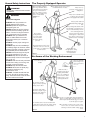
5. While holding the outer tube firmly
with your left hand, use your right hand
to pull the recoil starter handle until
resistance is felt, then pull quickly to
start the engine. See Figure 18.
CAUTION!
Do not pull the recoil starter to the end
of the rope travel. Pulling the recoil
starter to the end of the rope travel
can damage the starter.
Figure 17
Starting the Engine (continued)
When the Engine Starts
WARNING!
WARNING!
The cutting attachment may rotate
when the engine is started!
Never start the engine from the operating position.
n After the engine starts, allow the engine to warm up at idle 2 or 3 minutes
before operating the unit.
n After the engine is warm, pick
6. When the engine starts, slowly move
7. Operating the throttle will automatically
up the unit and clip on the shoulder
the choke lever to the "OPEN" posidisengage the fast idle setting.
strap or harness if so equipped.
tion. See Figure 19. (If the engine stops
See page 11.
IMPORTANT!
after the initial start, close the choke
n Advancing the throttle makes the cutIf the engine fails to start after several atand restart.)
ting attachment turn faster; releasing
tempts with the choke in the closed posithe throttle permits the attachment to
Choke Control
tion, the engine may be flooded with fuel.
(open position)
stop turning. If the cutting attachment
If flooding is suspected, move the choke
continues to rotate when the engine
lever to the open position and repeatedly
returns to idle, carburetor idle speed
pull the recoil starter to remove excess
should be adjusted (see below).
fuel and start the engine. If the engine
still fails to start, refer to the troubleshooting section of this manual.
Figure 19
Stopping the Engine
T272/T272X
IGNITION
SWITCH
OFF
Idle the engine briefly before stopping
(about 2 minutes), then slide the ignition switch to the “O” (OFF) position.
See Figure 20.
27029
Figure 20
Engine Idle Adjustment
The engine must return to idle speed
whenever the throttle lever is released.
Idle speed is adjustable, and must be set
low enough to permit the engine clutch to
disengage the cutting attachment when
the throttle is released.
Idle
Adjusting Screw
NOTE:
Carburetor fuel mixture adjustments are preset at factory on units with emission control
systems and cannot be serviced in the field.
Idle Speed Adjustment
WARNING!
The cutting attachment must NEVER
rotate at engine idle! If the idle speed
cannot be adjusted by the proceedure
described here, have the unit inspected at an authorized Shindaiwa dealer.
1. Place the unit on the ground, then start
the engine and allow it to idle for 2-3
minutes until warm.
10
3. If a tachometer is available, the engine
idle speed should be final adjusted to
3,000 (±250) rpm (min-1).
Figure 21
2. If the attachment rotates when the
engine is at idle, reduce the idle speed
by turning the idle adjustment screw
counter-clockwise.
See Figure 21.
Check Unit Condition
NEVER operate the unit with the cutting
attachment shield or other protective
devices (harness, ignition switch, blade
retention clip, etc.) removed!
WARNING!
A cutting attachment shield or other
protective device is no guarantee of
protection against thrown objects. YOU
MUST ALWAYS GUARD AGAINST
FLYING DEBRIS!
Shoulder Strap T272X
IMPORTANT!
Adjust the shoulder strap or harness so
the shoulder pad rests comfortably on
the off-side shoulder and the cutting path
of the cutting attachment is parallel to the
ground. Make sure all hooks and adjustment devices are secure.
T272
Use only authorized Shindaiwa parts and
accessories with your Shindaiwa trimmer
or brushcutter. Do not make modifications
to the unit without the written approval of
Shindaiwa, Inc.
ALWAYS make sure the cutting attachment is properly installed and firmly
tightened before operation.
NEVER use a cracked or warped
cutting attachment: replace it with a serviceable one.
ALWAYS make sure the cutting attachment fits properly into the appropriate
cutter holder. If a properly installed attachment vibrates, replace the attachment
with a new one and re-check.
ALWAYS stop the engine immediately
and check for damage if you strike a foreign object or if the unit becomes tangled.
Do not operate with broken or damaged
equipment.
NEVER allow the engine to operate at
high RPM’s without a load. Doing so
could damage the engine.
NEVER operate a unit with worn
or damaged fasteners or
attachment holders.
NEVER cut with dull blades. Doing so
will increase the risk of blade thrust and
may also damage your equipment.
Using a T272X with a Blade
Shoulder Strap
recommended for
use with grass
trimmers
WARNING!
Always wear a shoulder strap when
operating this unit with a blade. A
shoulder strap is also recommened
when using trimmer line.
Figure 22
NOTE:
Using a shoulder strap when operating
this unit with a blade allows you to maintain proper control of the unit and reduces
fatigue during extended operation.
NOTE:
Although a shoulder strap accessory is not
required for use with a grass trimmer, a
shoulder strap can increase operator comfort during extended periods of operation.
Cutting Grass—Units Equipped with a Trimmer Head
Your Shindaiwa T272 or T272X Grass
Trimmer may be equipped with one of
several Shindaiwa trimmer head models,
each with features for specific applications
and/or operational requirements.
For proper operation, always refer to the
instructions accompanying the trimmer
head being used. Available trimmer head
styles include:
n Semi-automatic. Trimmer line is
indexed when the operator taps the
trimmer head on the ground during
operation.
n Manual. The operator indexes line
manually while the grass trimmer
is stopped.
CAUTION!
Do not push the rotating line
into trees, wire fences or any material
that could tangle or break line ends.
Engine Operating Speeds
Operate the unit at full throttle while cutting grass.
WARNING!
Operation at low rpm (min-1) can lead
to premature clutch failure.
Trimming and Mowing Grass
n Fixed. The operator must stop the
unit and add new lengths of trimmer
line manually.
n Flail. This device, designed for clearing weeds and light brush, features
three nylon blades attached to the head
by pivots.
Figure 23
Hold the grass trimmer so the trimmer
head is angled slightly into the area to be
cut. To ensure maximum trimmer-line
service life, cut only
with the tip of the
trimmer line. Cut
grass by swinging
the unit’s trimmer
head from left to
right. Keep the trimmer head horizontal.
See Figure 23.
Edging
Tilt the handle about
100° to the right
(from horizontal)
and move forward,
holding the trimmer
vertical as shown in
Figure 24.
Figure 24
11
Using A Brushcutter Blade T272X
WARNING!
n Before working with a bladeequipped unit, always inspect
and clean the area of objects that
could interfere with or damage the
blade.
n Never use a blade near sidewalks,
fence posts, buildings or other
objects that could cause injury or
damage.
n Never use a blade for purposes
other than those for which it
was designed.
n Whenever you strike a hard object
with a blade, always stop the
brushcutter and carefully inspect
the blade for damage. NEVER
OPERATE THE UNIT WITH A
DAMAGED BLADE!
n A blade-equipped unit must be
equipped with a bicycle-type
handlebar or barrier bar as well as
a harness or shoulder strap.
n Always make sure the cutting
attachment shield is properly
installed before operating this unit.
The blade rotates counter-clockwise. For
best performance and to minimize being
stuck by debris, move the blade from right
to left while advancing on your work.
Position the blade so cuts are made
between the blade’s 7 o’clock and 11
o’clock positions (as viewed from above).
DO NOT cut between the 11 o’clock and 5
o’clock positions. See Figure 25.
Blade Thrust
Engine Operating Speeds
‘Blade thrust’ is a sudden sideways or
backward motion of the brushcutter. Such
motion may occur when the blade jams or
catches on an object such as a sapling tree
or tree stump. BE CONSTANTLY ALERT
FOR BLADE THRUST AND GUARD
AGAINST ITS EFFECTS!
Operate the unit at full throttle while
cutting. Best fuel efficiency is obtained by
releasing the throttle when swinging back
after a cut.
Brushcutter Handlebar
n Avoid cutting at low engine speeds. Doing so can lead to rapid clutch wear. In
addition, slow-speed operation tends to
cause grass and debris to wrap around
the cutting attachment.
WARNING!
n When cutting wood with a blade,
feed the blade slowly.
Never strike or “slam” the spinning blade against the wood.
n DO NOT use 2-tooth or nonShindaiwa approved 4-tooth
cutting blades with Shindaiwa
trimmers and brushcutters.
n To prevent possible engine damage, do
not allow the brushcutter to operate at
high speeds without a load.
Vertical cuts
Hold the trimmer with the blade at a 90°
angle to the ground so the blade’s bottom
edge rotates toward the operator. Move
the blade from top to bottom through the
cut, and cut only with the bottom edge of
the blade. See Figure 25.
A brushcutter’s handlebar helps prevent
the operator from moving forward or the
unit moving rearward; thus preventing
inadvertent bodily contact with the blade.
ALWAYS KEEP THE HANDLEBAR SECURELY IN PLACE ON THE UNIT!
WARNING!
When making vertical cuts,
never allow the blade to
exceed waist height.
Shoulder Strap
A shoulder strap provides additional
protection against blade thrust. Plus, a
shoulder strap gives significant support
and comfort to help ensure safe and efficient operation.
When operating a blade equipped
trimmer, make sure the shoulder strap is
adjusted properly to the operator using
the unit.
Cut on the left side of
the blade. Keep your
body outside the path
of blade rotation
Eleven�
O’Clock
DO NOT C
UT
Blade�
Rotation
OK To Cut
Figure 26
Seven�
O’Clock
Figure 25
12
�
Five�
O’Clock
General Maintenance
IMPORTANT!
MAINTENANCE, REPLACEMENT OR
REPAIR OF EMISSION CONTROL
DEVICES AND SYSTEMS MAY BE
PERFORMED BY ANY REPAIR ESTABLISHMENT OR INDIVIDUAL; HOWEVER, WARRANTY REPAIRS MUST
BE PERFORMED BY A DEALER OR
SERVICE CENTER AUTHORIZED BY
SHINDAIWA CORPORATION THE USE
OF PARTS THAT ARE NOT EQUIVALENT IN PERFORMANCE AND DURABILITY TO AUTHORIZED PARTS MAY
IMPAIR THE EFFECTIVENESS OF THE
EMISSION CONTROL SYSTEM AND
MAY HAVE A BEARING ON THE OUTCOME OF A WARRANTY CLAIM.
WARNING!
Non-standard parts may not operate
properly with your unit and may cause
damage and lead to personal injury.
NOTE:
Using non-standard replacement parts could
invalidate your Shindaiwa warranty.
Blades
Keep blades sharp and check blade condition frequently. If a blade’s performance
changes suddenly, stop the
engine and check the blade for cracks
or other damage. Replace a damaged
blade IMMEDIATELY!
WARNING!
Before performing any
maintenance, repair or
cleaning work on the unit, make sure
the engine and cutting attachment
are completely stopped. Disconnect
the spark plug wire before performing
service or maintenance work.
WARNING!
n Never repair a damaged blade
by welding, staightening, or by
modifying its shape. An altered
blade may break during operation, resulting in serious personal
injury.
n DO NOT use 2-tooth or NONShindaiwa approved 4-tooth
cutting blades on Shindaiwa trimmers or brushcutters.
n Blades are not interchangeable
between Shindaiwa edgers and
trimmer/brushcutter models.
Operating any unit with a blade or
attachment not approved for that
unit can be hazardous and may
cause serious injury.
Spark Plug
Keep the spark plug and wire connections
tight and clean.
Fasteners
Make sure nuts, bolts, and screws (except
carburetor adjusting screws)
are tight.
Daily Maintenance
Prior to each work day, perform the following:
n Check for loose or missing screws
or components. Make sure the tool
and cutting attachment are securely
fastened.
10-Hour Maintenance
Ever y 10 hours of operation
(more frequently in dusty or dirty
conditions):
Remove the air cleaner element. See Figure 27. Clean or replace as necessary. To
clean element: Wash it thoroughly in soap
and water. Let it dry before reinstalling
the element.
n Check the entire unit for leaking fuel or n Carefully remove any accumulation of
grease.
dirt or debris from the muffler
or the fuel tank. Dirt build-up in these
n Remove dirt or debris from the engine,
areas could cause the engine overheatcheck the cooling fins and air cleaner
ing, induce premature wear, or create a
for clogging and clean them as necesfire hazard.
sary.
Remove and clean
or replace the element
CAUTION!
Do not operate the unit if the air
cleaner or element is damaged, or if
the element is wet.
Figure 27
10/15-Hour Maintenance
Ever y 10 to 15 hours of operation:
Remove and clean the spark plug. Adjust the
spark plug electrode gap to 0.024-inch (0.6
mm). If the spark plug must be replaced,
use only a Champion CJ8Y or equivalent
spark plug of the correct heat range.
(For electro magnetic compliance (EMC)
use an NGK BMR6A resistor plug.)
See Figure 27.
CAUTION!
Before removing the spark plug, clean
the area around the plug
to prevent dirt and debris from getting
into the internal engine parts.
0.024"
(0.6mm)
Clean the spark plug
and check the gap at the
electrode.
CJ8Y
Figure 28
27030
13
50-Hour Maintenance
Every 50 hours of operation (more
n Use a hooked wire to extract the fuel
frequently in dusty or dirty conditions):
filter from inside the fuel tank. See Figure 30. Remove and replace the filter
n Remove and clean the cylinder cover and
element. Before reinstalling the filter,
clean grass and dirt from the cylinder fins.
inspect the condition of the fuel line.
n Remove the cutting attachment, cutting
If damage or deterioration are noted,
attachment holder and gear shaft colthe unit should be removed from
lar. Remove the filler plug from the side
service until it can be inspected by a
of the gearcase and press new grease
Shindaiwa-trained service technician.
into the gearcase until the old grease
is pushed out. Use only lithium-base
CAUTION!
grease such as Shindaiwa Gear Case
Make sure you do not pierce the fuel
Lubricant or equivalent. See Figure 29.
line with the end of the hooked wire.
The line is delicate and can be damaged easily.
New Grease
Old
Grease
Hooked
Wire
Figure 30
Gear Shaft Collar
Figure 29
135-Hour Maintenance
Every 135 hours of operation,
remove and clean the muffler.
5. Remove the spark arrester screen and
clean with a stiff bristle brush.
6. Gently tap the muffler on a wood surface to dislodge any loose carbon.
WARNING!
Never operate this unit with a damaged or missing muffler or spark
arrester! Operating with missing or
damaged exhaust components is a
fire hazard and could also damage
your hearing.
7. Inspect the cylinder exhaust port for
carbon buildup.
Rear Muffler
Shield
Forward
Muffler
Shield
5 mm Muffler
Screws
2. Remove the four 4 mm engine cover
screws (two in the back and two in the
front of the cover) and lift the cover
from the engine.
3. Remove the two 5 mm muffler screws.
Remove the lower muffler screw, then
lift the muffler assembly from the
engine.
14
8. Reassemble the muffler in the reverse
order of disassembly.
Spark Arrester Screen
1. Remove the spark plug boot.
4. Seperate the muffler from the forward
muffler shield, while observing the
orientation of the components.
See Figure 31.
IMPORTANT!
If you note excessive carbon buildup, consult with an authorized servicing dealer.
Rear Muffler
Shield Screw
Muffler
Figure 31
Lower Muffler
Screw
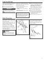
Long Term Storage
Whenever the unit will not be used for 30
days or longer, use the following procedures to prepare it for storage:
To remove the remaining fuel from the
fuel lines and carburetor and with the fuel
drained from the fuel tank.
n Clean external parts thoroughly.
1. Prime the primer bulb until no more
fuel is passing through.
n Drain all the fuel from the fuel tank.
IMPORTANT!
All stored fuels should be stabilized with
a fuel stabilizer such as STA-BIL™ , if
oil with fuel stabilizer is not used.
2. Start and run the engine until stops
running.
3. Repeat steps 1 and 2 until the engine
will no longer start.
CAUTION!
Gasoline stored in the carburetor for
extended periods can cause hard starting and could also lead to increased
service and maintenance costs.
n Remove the spark plug and pour about
1/4 ounce of 2-cycle mixing oil into the
cylinder through the spark plug hole.
Slowly pull the recoil starter 2 or 3
times so oil will evenly coat the interior
of the engine. Reinstall the spark plug.
n Before storing the unit, repair or replace any worn or damaged parts.
n Remove the air cleaner element from
the carburetor and clean it thoroughly
with soap and water. Let dry before
reinstalling the element.
n Store the unit in a clean, dust-free area.
Blade Sharpening
When the blade’s cutting edges become
slightly dull, they can be resharpened with
a few strokes of a file.
In order to keep the blade in balance, all
cutting edges must be sharpened equally.
Multiple-tooth Circular Blade
Use a round file to maintain a radius of
0.04 to 0.06" (1 to 1.5 mm) at the base of
each tooth. Cutting edges must be offset
equally on each side.
Shindaiwa Tornado™ Blade
To sharpen the cutters on a Shindaiwa
Tornado Blade, use a 7/32-inch round
file. File the leading edge of each tooth to
a razor edge. The top plate of each tooth
should angle back 30°.
Filing Direction
WARNING!
Sharpen the cutting teeth only. DO
NOT alter the contour of the blade in
any way.
Round
File
Round
File
30°
Figure 32
Filing Direction
Figure 33
15
Troubleshooting Guide
ENGINE DOES NOT START
What To Check
Possible Cause
Remedy
>ÕÌÞÊÀiVÊÃÌ>ÀÌiÀ°
Õ`ÊÊÌ
iÊVÀ>V>Ãi°
ÌiÀ>Ê`>>}i°
ÃÕÌÊÜÌ
Ê>Ê>ÕÌ
Àâi`ÊÃiÀÛV}Ê`i>iÀ°
NO
ÃiÊë>ÀÊ«Õ}°
ÝViÃÃÊÜi>ÀÊÊ
VÞ`iÀ]Ê«ÃÌ]ÊÀ}ð
/}
ÌiÊ>`ÊÀiÌiÃÌ°
ÃÕÌÊÜÌ
Ê>Ê>ÕÌ
Àâi`ÊÃiÀÛV}Ê`i>iÀ°
NO
ÕiÊVÀÀiVÌ]ÊÃÌ>i]ÊÀ
VÌ>>Ìi`ÆÊÝÌÕÀi
VÀÀiVÌ°
,ivÊÜÌ
ÊvÀiÃ
]ÊVi>ÊÕi>`i`Ê}>ÃiÊÜÌ
Ê>Ê«Õ«ÊVÌ>iÊvÊnÇÊÀÊ
}
iÀÊÝi`ÊÜÌ
ÊÓVÞViÊ>ÀÊVi`ÊÝ}ÊÊÌ
>ÌÊiiÌÃÊÀÊiÝVii`ÃÊ
-"Ê>`ÉÀÊ-"Ê
ÊV>ÃÃvi`ÊÃÊ>ÌÊ>Êxä\£Ê}>ÃiÉÊÀ>Ì°
NO
iVÊvÀÊV}}i`ÊvÕi
vÌiÀÊ>`ÉÀÊÛiÌ°
i>Ê>ÃÊÀiµÕÀi`ÆÊ
ÀiÃÌ>ÀÌ°
iÃÊÌ
iÊi}iÊ NO
VÀ>
YES
`
V«ÀiÃö
YES
iÃÊÌ
iÊÌ>
VÌ>ÊvÀiÃ
vÕiÊvÊÌ
i
«À«iÀÊ}À>`i
YES
ÃÊvÕiÊÛÃLi
>`ÊÛ}Ê
Ì
iÊÀiÌÕÀÊi
Ü
iÊ«À}
YES
ÃÊÌ
iÀiÊë>ÀÊ>Ì NO
Ì
iÊë>ÀÊ«Õ}
ÜÀiÊÌiÀ>
YES
iVÊÌ
iÊ
ë>ÀÊ«Õ}°
16
ÛiÊÃÜÌV
ÊÌʺ»Ê" ®Ê«ÃÌÊ>`ÊÀiÃÌ>ÀÌ°
/
iÊ}ÌÊÃÜÌV
ÊÃÊʺ"»Ê"®Ê«ÃÌ°
-
ÀÌi`Ê}ÌÊ}ÀÕ`° ÃÕÌÊÜÌ
Ê>Ê>ÕÌ
Àâi`ÊÃiÀÛV}Ê`i>iÀ°
>ÕÌÞÊ}ÌÊÕÌ°
vÊÌ
iÊ«Õ}ÊÃÊÜiÌ]ÊiÝViÃÃ
vÕiÊ>ÞÊLiÊÊÌ
i
VÞ`iÀ°
À>ÊÌ
iÊi}iÊÜÌ
ÊÌ
iÊ«Õ}ÊÀiÛi`]ÊÀiÃÌ>ÊÌ
iÊë>ÀÊ«Õ}]Ê
>`ÊÀiÃÌ>ÀÌ°
/
iÊ«Õ}ÊÃÊvÕi`
ÀÊ«À«iÀÞÊ}>««i`°
i>Ê>`ÊÀi}>«ÊÌ
iÊë>ÀÊ«Õ}ÊÌÊä°äÓ{ÊV
Êä°ÈÊ®°Ê,iÃÌ>ÀÌ°
/
iÊ«Õ}ÊÃÊ`>>}i`
ÌiÀ>ÞÊÀÊvÊÌ
i
ÜÀ}ÊÃâi°
,i«>ViÊÌ
iÊë>ÀÊ«Õ}ÊÜÌ
Ê>Ê
>«Ê
n9ÊÀÊiµÕÛ>iÌÊë>ÀÊ
«Õ}ÊvÊÌ
iÊVÀÀiVÌÊ
i>ÌÊÀ>}i°Ê`ÕÃÌÊÌ
iÊë>ÀÊ«Õ}ÊiiVÌÀ`iÊ}>«ÊÌÊ
ä°äÓ{V
Êä°ÈÊ®°Ê
Troubleshooting Guide (continued)
LOW POWER OUTPUT
What To Check
ÃÊÌ
iÊi}i
ÛiÀ
i>Ì}
}iÊÃÊÀÕ}
>ÌÊ>Êëii`ðÊ
>ÞÊ>ÃÊ
>Ûi
L>VÊÃi
>`ÉÀÊÕLÕÀi`
vÕiÊ>ÌÊÌ
i
iÝ
>ÕÃÌ°
Possible Cause
Remedy
"«iÀ>ÌÀÊÃÊÛiÀÜÀ}
Ì
iÊÕÌ°
-
ÀÌiÊÌÀiÀÊi°Ê
ÕÌÊ>ÌÊ>ÊÃÜiÀÊÀ>Ìi°
>ÀLÕÀiÌÀÊÝÌÕÀiÊÃ
ÌÊi>°
ÃÕÌÊÜÌ
Ê>Ê>ÕÌ
Àâi`ÊÃiÀÛV}Ê`i>iÀ°
«À«iÀÊvÕiÊÀ>Ì°
,ivÊÜÌ
ÊvÀiÃ
]ÊVi>ÊÕi>`i`Ê}>ÃiÊÜÌ
Ê>Ê«Õ«ÊVÌ>iÊvÊnÇÊÀÊ
}
iÀÊÝi`ÊÜÌ
ÊÓVÞViÊ>ÀÊVi`ÊÝ}ÊÊÌ
>ÌÊiiÌÃÊÀÊiÝVii`ÃÊ
-"Ê>`ÉÀÊ-"Ê
ÊV>ÃÃvi`ÊÃÊ>ÌÊ>Êxä\£Ê}>ÃiÉÊÀ>Ì°
>]Êv>ÊVÛiÀ]ÊVÞ`iÀ
vÃÊ`ÀÌÞÊÀÊ`>>}i`°
i>]ÊÀi«>ÀÊÀÊÀi«>ViÊ>ÃÊiViÃÃ>ÀÞ°
>ÀLÊ`i«ÃÌÃÊÊÌ
iÊ
«ÃÌÊÀÊÊÌ
iÊÕvviÀ°
ÃÕÌÊÜÌ
Ê>Ê>ÕÌ
Àâi`ÊÃiÀÛV}Ê`i>iÀ°
}}i`Ê>ÀÊVi>iÀÊ
iiiÌ°
-iÀÛViÊÌ
iÊ>ÀÊVi>iÀ°
ÃiÊÀÊ`>>}i`
ë>ÀÊ«Õ}°
/}
ÌiÊÀÊÀi«>Vi°
,i«>ViÊÌ
iÊë>ÀÊ«Õ}ÊÜÌ
Ê>Ê
>«Ê
n9ÊÀÊiµÕÛ>iÌÊë>ÀÊ
«Õ}ÊvÊÌ
iÊVÀÀiVÌÊ
i>ÌÊÀ>}i°Ê`ÕÃÌÊÌ
iÊë>ÀÊ«Õ}ÊiiVÌÀ`iÊ}>«Ê
ÌÊä°äÓ{V
Êä°ÈÊ®°Ê
ÀÊi>>}iÊÀÊV}}i`
vÕiÊi°
,i«>ÀÊÀÊÀi«>ViÊvÕiÊvÌiÀÊ>`ÉÀÊvÕiÊi°
7>ÌiÀÊÊÌ
iÊvÕi°
,ivÊÜÌ
ÊvÀiÃ
]ÊVi>ÊÕi>`i`Ê}>ÃiÊÜÌ
Ê>Ê«Õ«ÊVÌ>iÊvÊnÇÊÀÊ
}
iÀÊÝi`ÊÜÌ
ÊÓVÞViÊ>ÀÊVi`ÊÝ}ÊÊÌ
>ÌÊiiÌÃÊÀÊiÝVii`ÃÊ
-"Ê>`ÉÀÊ-"Ê
ÊV>ÃÃvi`ÊÃÊ>ÌÊ>Êxä\£Ê}>ÃiÉÊÀ>Ì°
*ÃÌÊÃiâÕÀi°
ÃÕÌÊÜÌ
Ê>Ê>ÕÌ
Àâi`ÊÃiÀÛV}Ê`i>iÀ°
>ÕÌÞÊV>ÀLÕÀiÌÀÊ>`ÉÊÊÊÊÊÊÊÊÊÊÊÊÊÊ
ÃÕÌÊÜÌ
Ê>Ê>ÕÌ
Àâi`ÊÃiÀÛV}Ê`i>iÀ°
ÀÊ`>«
À>}°
}iÊÃ
V}°
"ÛiÀ
i>Ì}ÊV`Ì°
-iiÊ>LÛi°
«À«iÀÊvÕi°
iVÊvÕiÊVÌ>iÊÀ>Ì}ÆÊV
iVÊvÀÊ«ÀiÃiViÊvÊ>V
ÊÊÌ
iÊvÕiÊ
«}°Ê®°Ê,ivÕiÊ>ÃÊiViÃÃ>ÀÞ°
>ÀLÊ`i«ÃÌÃÊÊÌ
i
VLÕÃÌÊV
>LiÀ°
ÃÕÌÊÜÌ
Ê>Ê>ÕÌ
Àâi`ÊÃiÀÛV}Ê`i>iÀ°
17
Troubleshooting Guide (continued)
ADDITIONAL PROBLEMS
Symptom
*À
>VViiÀ>Ì°
}iÊÃÌ«Ã
>LÀÕ«ÌÞ°
}iÊ`vvVÕÌ
ÌÊÃ
ÕÌÊvv°
ÕÌÌ}Ê
>ÌÌ>V
iÌÊ
ÛiÃÊ>ÌÊ
i}iÊ`i°
ÝViÃÃÛiÊ
ÛLÀ>Ì°
Possible Cause
Remedy
}}i`Ê>ÀÊVi>iÀ
iiiÌ°
i>ÊÌ
iÊ>ÀÊVi>iÀÊiiiÌ°
}}i`ÊvÕiÊvÌiÀ°
,i«>ViÊÌ
iÊvÕiÊvÌiÀ°
>ÀLÕÀiÌÀÊÝÌÕÀiÊ
ÌÊi>°
ÃÕÌÊÜÌ
Ê>Ê>ÕÌ
Àâi`ÊÃiÀÛV}Ê`i>iÀ°
`iÊëii`ÊÃiÌÊÌÊÜ°
`ÕÃÌ\ÊÎ]äääÊÓxä®ÊÀ«Ê£®
-ÜÌV
ÊÌÕÀi`Êvv°
,iÃiÌÊÌ
iÊÃÜÌV
Ê>`ÊÀiÃÌ>ÀÌ°
ÕiÊÌ>Êi«ÌÞ°
,ivÕi°
}}i`ÊvÕiÊvÌiÀ°
,i«>ViÊvÌiÀ°
7>ÌiÀÊÊÌ
iÊvÕi°
,ivÊÜÌ
ÊvÀiÃ
]ÊVi>ÊÕi>`i`Ê}>ÃiÊÜÌ
Ê>Ê«Õ«ÊVÌ>iÊvÊnÇÊÀÊ
}
iÀÊÝi`ÊÜÌ
ÊÓVÞViÊ>ÀÊVi`ÊÝ}ÊÊÌ
>ÌÊiiÌÃÊÀÊiÝVii`ÃÊ
-"Ê>`ÉÀÊ-"Ê
ÊV>ÃÃvi`ÊÃÊ>ÌÊ>Êxä\£Ê}>ÃiÉÊÀ>Ì°
-
ÀÌi`Êë>ÀÊ«Õ}ÊÀ
ÃiÊÌiÀ>°
i>Ê>`ÊÀi«>ViÊë>ÀÊ«Õ}]ÊÌ}
ÌiÊÌ
iÊÌiÀ>°
}ÌÊv>ÕÀi°
ÃÕÌÊÜÌ
Ê>Ê>ÕÌ
Àâi`ÊÃiÀÛV}Ê`i>iÀ°
*ÃÌÊÃiâÕÀi°
ÃÕÌÊÜÌ
Ê>Ê>ÕÌ
Àâi`ÊÃiÀÛV}Ê`i>iÀ°
ÀÕ`ÊÃÌ«®ÊÜÀiÊÃ
`ÃViVÌi`]ÊÀÊÃÜÌV
Ê
ÃÊ`iviVÌÛi°
/iÃÌÊ>`ÊÀi«>ViÊ>ÃÊÀiµÕÀi`°
"ÛiÀ
i>Ì}Ê`ÕiÊÌÊ
VÀÀiVÌÊë>ÀÊ«Õ}°
,i«>ViÊÌ
iÊë>ÀÊ«Õ}ÊÜÌ
Ê>Ê
>«Ê
n9ÊÀÊiµÕÛ>iÌÊë>ÀÊ
«Õ}ÊvÊÌ
iÊVÀÀiVÌÊ
i>ÌÊÀ>}i°Ê`ÕÃÌÊÌ
iÊë>ÀÊ«Õ}ÊiiVÌÀ`iÊ}>«ÊÌÊ
ä°äÓ{V
Êä°ÈÊ®°Ê
"ÛiÀ
i>Ìi`Êi}i°
`iÊi}iÊÕÌÊV°Ê
}iÊ`iÊÌÊ
}
°
-iÌÊ`i\ÊÎ]äääÊÓxä®ÊÀ«Ê£®
ÀiÊVÕÌV
ÊëÀ}ÊÀ
ÜÀÊVÕÌV
ÊëÀ}ÊLÃð
,i«>ViÊëÀ}ÉÃ
iÃÊ>ÃÊÀiµÕÀi`]ÊV
iVÊ`iÊëii`°
7>À«i`ÊÀÊ`>>}i`Ê
VÕÌÌ}Ê>ÌÌ>V
iÌ°
ëiVÌÊ>`ÊÀi«>ViÊ>ÃÊiViÃÃ>ÀÞ°
ÃiÊVÕ«iÀ°
/}
ÌiÊVÕ«iÀÊÃiVÕÀiÞ°
iÌÊ>ÊÃ
>vÌÉÜÀÊÀ ëiVÌÊ>`ÊÀi«>ViÊ>ÃÊiViÃÃ>ÀÞ°
`>>}i`ÊLÕÃ
}ð
18
The following statement only applies to United States and its territories
Shindaiwa Corporation
Federal Emission Design And Defect Limited Warranty
Utility And Lawn And Garden Engines
Shindaiwa Corporation warrants to the initial purchaser and each
subsequent owner, that this utility equipment engine (herein
engine) is designed, built and equipped to conform at the time of
initial sale, to all applicable regulations of the U.S. Environmental
Protection Agency (EPA), and that the engine is free of defects in
materials and workmanship that would cause this engine to fail
to conform with EPA regulations during its warranty period. This
emission warranty is applicable in all States, except the State of
California.
For parts listed under PARTS COVERED, the dealer authorized by
Shindaiwa Corporation will, at no cost to you, make the necessary
diagnosis, repair, or replacement of any defective emission-related
component to ensure that the engine complies with applicable U.S.
EPA regulations.
MANUFACTURERS WARRANTY COVERAGE
When sold within the U.S., this engine’s emission control system is
warranted for a period of two (2) years from the date this product is first
delivered to the original retail purchaser.
OWNER’S WARRANTY RESPONSIBILITIES
As the engine owner, you are responsible for the performance of the
required maintenance listed in your owner’s manual. Shindaiwa Corporation recommends that you retain all receipts covering maintenance on your
engine, but Shindaiwa Corporation cannot deny a warranty claim solely
for the lack of receipts or for your failure to ensure the performance of all
scheduled maintenance.
As the engine owner, you should however be aware that Shindaiwa Corporation may deny your warranty coverage if your engine or a part has failed
due to abuse, neglect, improper maintenance or unapproved modifications.
You are responsible for presenting your engine to the nearest dealer authorized by Shindaiwa Corporation when a problem exists.
If your Shindaiwa Dealer is unable to answer questions regarding your
warranty rights and responsibilities, you should then contact your
Shindaiwa Distributor.
For the name and telephone number of the Shindaiwa Distributor in your
area, please call Shindaiwa Inc. at (503) 692-3070 between the hours of 8:00
AM and 5:00 PM Pacific Standard Time.
PARTS COVERED
Listed below are the parts covered by the Federal Emission Design and
Defect Warranty. Some parts listed below may require scheduled maintenance and are warranted up to the first scheduled replacement of that part.
The warranted parts include:
1.Carburetor Internal Components
• Valve Assembly-throttle, Jet, Metering Diaphragm
2. Ignition System Components
• Ignition Coil
• Flywheel Rotor
The emission control system for your particular Shindaiwa engine may
also include certain related hoses and connectors.
MAINTENANCE AND REPAIR REQUIREMENTS
You are responsible for the proper use and maintenance of the engine. You
should keep all receipts and maintenance records covering the performance of regular maintenance in the event questions arise. These receipts
and maintenance records should be transferred to each subsequent owner
of the engine. Shindaiwa Corporation reserves the right to deny warranty
coverage if the owner has not properly maintained the engine. Shindaiwa
Corporation will not deny warranty repairs, however, solely because of the
lack of repair, maintenance or failure to keep maintenance records.
MAINTENANCE, REPLACEMENT OR REPAIR OF EMISSION CONTROL
DEVICES AND SYSTEMS MAY BE PERFORMED BY ANY REPAIR ESTABLISHMENT OR INDIVIDUAL; HOWEVER, WARRANTY REPAIRS MUST
BE PERFORMED BY A DEALER OR SERVICE CENTER AUTHORIZED
BY SHINDAIWA CORPORATION THE USE OF PARTS THAT ARE NOT
EQUIVALENT IN PERFORMANCE AND DURABILITY TO AUTHORIZED
PARTS MAY IMPAIR THE EFFECTIVENESS OF THE EMISSION CONTROL SYSTEM AND MAY HAVE A BEARING ON THE OUTCOME OF A
WARRANTY CLAIM.
If other than the parts authorized by Shindaiwa Corporation are used for
maintenance replacements or for the repair of components affecting emission control, you should assure yourself that such parts are warranted by
their manufacturer to be equivalent to the parts authorized by Shindaiwa
Corporation in their performance and durability.
OBTAINING WARRANTY SERVICE
All repairs qualifying under this limited warranty must be performed by a
dealer authorized by Shindaiwa Corporation
If any emission-related part is found defective during the warranty period,
it is your responsibility to present the product to an authorized Shindaiwa
dealer. Bring your sales receipts showing the date of purchase for this
engine. The dealer authorized by Shindaiwa Corporation will perform the
necessary repairs or adjustments within a reasonable amount of time and
furnish you with a copy of the repair order. All parts and accessories replaced under this warranty become the property of Shindaiwa Corporation
To locate an authorized Shindaiwa dealer near you, contact your Shindaiwa
Distributor. For the name and telephone number of the Shindaiwa Distributor in your area, please call Shindaiwa Inc. at (503) 692-3070 between
the hours of 8:00 AM and 5:00 PM Pacific Standard Time.
THIS WARRANTY IS ADMINISTERED BY
Shindaiwa Inc.
11975 S.W. Herman Rd.
Tualatin OR. 97062
(503) 692-3070
LIMITATIONS
The Federal Emission Design and Defect Warranty shall not cover any of
the following:
(a)conditions resulting from tampering, misuse, improper adjustment
(unless they were made by the dealer or service center authorized
by Shindaiwa Corporation during a warranty repair), alteration,
accident, failure to use the recommended fuel and oil, or not performing required maintenance services,
(b)the replacement parts used for required maintenance services,
(c)consequential parts used for required maintenance services,
(d)diagnosis and inspection fees that do not result in eligible warranty
service being performed, and
(e)any non-authorized replacement part, or malfunction of authorized
parts due to use of non-authorized parts.
19
NOTES
Shindaiwa Inc.
11975 S.W. Herman Rd.
Tualatin, Oregon 97062
Telephone:503 692-3070
Fax:
503 692-6696
www.shindaiwa.com
Shindaiwa Corporation
6-2-11 Ozuka-Nishi
Asaminami-Ku, Hiroshima
731-3167, Japan
Telephone:81-82-849-2220
Fax:
81-82-849-2481
©2007 Shindaiwa, Inc.
Part Number 81647
Revision 1/07
Shindaiwa is a registered trademark
of Shindaiwa, Inc.
Specifications subject to change without notice.
NOTAS:
Shindaiwa Inc.
11975 S.W. Herman Rd.
Tualatin, Oregon 97062 USA
Teléfono: 503 692-3070
Fax:
503 692-6696
www.shindaiwa.com
Shindaiwa Corporation
Head Office: 6-2-11, Ozuka-Nishi
Asaminami-Ku, Hiroshima
731-3167, Japan
Teléfono: 81-82-849-2220
Fax:
81-82-849-2481
©2006 Shindaiwa, Inc.
Despida el Número 81647
Revisión 1/07
Shindaiwa es una marca registrada
registrada de Shindaiwa, Inc.
Especificaciones sujetas a cambio sin previo aviso.
Shindaiwa Corporation
Garantía limitada de defectos y diseño de emisiones federales
Motores de uso general y para parques y jardines
Shindaiwa Corporation garantiza al comprador inicial y a cada
propietario siguiente, que este motor para equipos de uso general
(de aquí en adelante motor) está diseñado, fabricado y equipado para
cumplir, en el momento de la venta inicial, con todas los reglamentos
vigentes de la Administración de Protección Ambiental de EE.UU.
(EPA) y que no tiene defectos materiales ni de mano de obra que
pudieran hacer que el motor no cumpla con las reglamentaciones de la
EPA durante el período de vigencia de la garantía. Esta garantía sobre
normas de emisión rige para todos los estados, excepto para el Estado
de California.
Para las piezas listadas en PIEZAS CUBIERTAS, el Distribuidor
autorizado por Shindaiwa Corporation efectuará, sin costo para el
propietario, los diagnósticos, reparaciones o reemplazos necesarios de
cualquier componente defectuoso en relación con las emisiones para
asegurar que el motor cumpla con las reglamentaciones de la EPA de
EE.UU. aplicables.
COBERTURA DE LA GARANTÍA DEL FABRICANTE
Cuando este equipo se vende en EE.UU., el sistema de control de
emisiones del mismo está garantizado por un período de 2 (dos) años a
partir de la fecha en que el producto haya sido entregado por primera
vez al comprador minorista original.
RESPONSABILIDADES DEL PROPIETARIO RESPECTO DE
LA GARANTÍA
Como propietario del motor, usted es responsable de la
realización del mantenimiento requerido listado en su manual del
propietario. Shindaiwa Corporation le recomienda conservar todos
los comprobantes que cubran el mantenimiento de su motor, pero
Shindaiwa Corporation no puede negar una reclamación de garantía
exclusivamente debido a la falta de comprobantes o porque usted
no pueda asegurar la realización de todos los mantenimientos
programados.
Como propietario del motor, usted deberá sin embargo estar enterado
de que Shindaiwa Corporation podrá negarle cobertura de garantía si
el motor o alguna pieza ha fallado debido a uso abusivo, negligencia,
mantenimiento inadecuado o modificaciones no autorizadas.
Usted es responsable de la presentación del motor al distribuidor
autorizado de Shindaiwa Corporation más cercano cuando exista algún
problema.
Si el distribuidor Shindaiwa no puede responder su pregunta con
respecto a sus derechos y responsabilidades de garantía, deberá
entonces comunicarse con su distribuidor regional de Shindaiwa.
Para obtener el nombre y el número telefónico del distribuidor
de Shindaiwa en su localidad, comuníquese con Shindaiwa Inc., al
(503) 692-3070 de 8:00 a.m. a 5:00 p.m., hora del Pacífico.
PIEZAS CUBIERTAS
A continuación se listan las piezas cubiertas por la garantía de
diseño federal de emisiones y defectos. Algunas partes mencionadas
a continuación pueden requerir mantenimiento periódico y están
garantizadas hasta el primer reemplazo programado de las mismas. Las
partes garantizadas incluyen:
1. Componentes internos del carburador
• Armado y medición del chorro y el diafragma
2. Componentes del sistema de encendido
• Bobina de encendido
• Rotor del volante
El sistema de control de emisiones del motor Shindaiwa puede
también incluir ciertas mangueras y conexiones afines.
LIMITACIONES
La garantía por diseño federal de emisiones y defectos no cubrirá
nada de lo siguiente:
(a)Condiciones que resulten de una intervención no autorizada,
un mal uso, un ajuste inapropiado (a menos de que los hubieran
efectuado un distribuidor o un centro de servicio autorizado
de Shindaiwa Corporation, en el curso de una reparación de
garantía), una alteración, accidente, omisión en el uso del
combustible y aceite recomendados o de una omisión en el
cumplimiento de los servicios de mantenimiento requeridos,
(b)Los repuestos usados para los servicios de mantenimiento
requeridos,
(c)Partes consecuenciales utilizadas para efectuar los servicios de
mantenimiento requeridos,
(d)Cuotas de diagnóstico e inspección que no resulten en servicios
cubiertos por la garantía,
(e)Todo repuesto no autorizado o la falla de partes autorizadas que
pudieran deberse al uso de partes no autorizadas.
REQUISITOS DE MANTENIMIENTO Y REPARACIÓN
Usted es responsable del uso y mantenimiento correctos del motor.
Usted deberá conservar todos los comprobantes y registros de
mantenimiento que cubran la realización de mantenimiento regular
en caso de que surjan preguntas. Estos comprobantes y los registros
de mantenimiento deberán ser transferidos a cada propietario
subsiguiente del motor. Shindaiwa Corporation se reserva el derecho
a negar la cobertura de garantía si el propietario no ha mantenido
correctamente el motor. Shindaiwa Corporation, sin embargo, no negará
reparaciones bajo garantía por el solo hecho de no haberse efectuado
reparaciones o mantenimiento o por la omisión de mantener registros
de mantenimiento.
EL MANTENIMIENTO, REEMPLAZO O REPARACIÓN DE
DISPOSITIVOS Y SISTEMAS DE CONTROL DE EMISIONES PUEDE
SER REALIZADO POR CUALQUIER ESTABLECIMIENTO O PERSONA
DEDICADOS A ELLO; SIN EMBARGO, LAS REPARACIONES
CUBIERTAS POR LA GARANTÍA DEBEN SER LLEVADAS A CABO
POR UN DISTRIBUIDOR O CENTRO DE SERVICIO AUTORIZADO
POR SHINDAIWA CORPORATION EL EMPLEO DE PIEZAS QUE NO
SON EQUIVALENTES EN RENDIMIENTO Y DURABILIDAD A LAS
PIEZAS AUTORIZADAS PUEDE REDUCIR LA EFECTIVIDAD DEL
SISTEMA DE CONTROL DE EMISIONES Y PUEDE AFECTAR EL
RESULTADO DE UNA RECLAMACIÓN DE GARANTÍA.
Si se utilizaran piezas no autorizadas por Shindaiwa Corporation para
reemplazos por mantenimiento o reparación de componentes que afecte
el control de emisiones, se deberá asegurar que dichas piezas estén
garantizadas por el fabricante como equivalentes a las piezas autorizadas
por Shindaiwa Corporation en lo relativo al rendimiento
y durabilidad.
SOLICITUDES DE SERVICIO DE GARANTÍA
Toda reparación realizada conforme a los términos de esta garantía
limitada deberá ser llevada a cabo por un distribuidor autorizado por
Shindaiwa Corporation.
Si cualquier pieza vinculada con las emisiones es encontrada
defectuosa durante el período de garantía, es su responsabilidad
presentar el producto a un distribuidor autorizado de Shindaiwa.
Presente sus comprobantes de venta en los que aparezca la fecha de
compra del motor. El distribuidor autorizado de Shindaiwa Corporation
llevará a cabo las reparaciones o ajustes necesarios en un lapso
razonable, suministrándole una copia de dicha orden de reparación.
Todas las piezas y accesorios reemplazados bajo esta garantía pasarán a
ser propiedad de Shindaiwa Corporation.
Para localizar a un agente de servicio Shindaiwa más cercano a usted,
favor de ponerse en contacto con su distribuidor Shindaiwa. Para
obtener el nombre y el número telefónico del distribuidor de Shindaiwa
en su localidad, comuníquese con Shindaiwa Inc., al (503) 692-3070 de
8:00 a.m. a 5:00 p.m., hora del Pacífico.
ESTA GARANTÍA ES ADMINISTRADA POR:
Shindaiwa Inc.
11975 S.W. Herman Rd.
Tualatin OR 97062
(503) 692-3070
19
Guía Diagnóstico (continuación)
PROBLEMAS ADICIONALES
Síntoma
ViiÀ>VÊ
`ivViÌi°
>LiÊiÊvÌÀÊ`iÊVLÕÃÌLi
ÌÀÊ`iÊVLÕÃÌLiÊ
LÃÌÀÕ`°
«iÊiÊiiiÌÊ`iÊ>Ài°
ÌÀÊ`iÊ>ÀiÊLÃÌÀÕ`°
Remedio
Posible Causa
>ÊiâV>Ê`iÊV>ÀLÕÀ>`ÀÊ ÃÕÌiÊVÊÃÕÊ>}iÌiÊ`iÊÃiÀÛVÊ>ÕÌÀâ>`
iÃÊÕÞÊ«LÀi°
Ê
>ÀV
>Ê>Ê>ÕÃÌ>`>Ê ÕÃÌi\Ê>ÊÎ]äääÊ,*ʳÊÓxä®ÊÀ«Ê£®
ÕÞÊL>>°
ÊÌÀÊÃiÊ
>«>}>Ê
>LÀÕ«Ì>iÌi
-iÊ
>ViÊ`vVÊ
>«>}>ÀÊiÊÌÀ°
ÊÌiÀÀÕ«ÌÀÊiÃÌ?ÊiÊ
>Ê«ÃVÊ`iÊ>«>}>`°Ê
iÊiÊÌiÀÀÕ«ÌÀÊÞÊÛÕiÛ>Ê>ÀÀ>V>À°
ÊÌ>µÕiÊ`iÊVLÕÃÌLiÊ 6ÕiÛ>Ê>Êi>À°Ê
iÃÌ?ÊÛ>V°
ÃÕÌiÊVÊÃÕÊ>}iÌiÊ`iÊÃiÀÛVÊ>ÕÌÀâ>`°
*ÃÌÊÌÀ>L>`°
ÃÕÌiÊVÊÃÕÊ>}iÌiÊ`iÊÃiÀÛVÊ>ÕÌÀâ>`°
>>ÊiÊiÊÃÃÌi>Ê
`iÊiVi``°
«iÊÞÊV>LiÊ>ÊLÕ>ÆÊ«ÀiÌiÊiÊÌiÀ>°Ê
Õ>Ê`iviVÌÕÃ>ÊÊ
ÌiÀ>Êv°
6ÕiÛ>Ê>Êi>ÀÊVÊVLÕÃÌLiÊvÀiÃV]Ê«ÊÞÊ
ÃÊ«ÊVÊÕÊVÌ>>iÊ`iÊnÇÊÊÃÕ«iÀÀÊiâV>`Ê
VÊ>ViÌiÊ`iÊiâV>Ê«>À>ÊÌÀiÃÊ`iÊÓÊÌi«ÃÊ-
`>Ü>Ê
ivÀ>`Ê«ÀÊ>ÀiʵÕiÊVÕ«iÊÊiÝVi`iÊÃÊ>ViÌiÃÊV>ÃvV>`ÃÊ
-"ÊÞÉÊ-"Ê
Ê>ÊÕ>Ê«À«ÀVÊ`iÊxä\£Ê`iÊ}>Ã>É>ViÌi°
}Õ>ÊiÊiÊVLÕÃÌLi°
Ê
>LiÊiÊvÌÀÊ`iÊVLÕÃÌLi°
ÌÀÊ`iÊVLÕÃÌLiÊ
LÃÌÀÕ`°
>ÊViÝÊ>ÊÌiÀÀ>ÊiÃÌ?Ê *ÀÕiLiÊÞÊÀii«>ViÊVÊÃi>ÊÀiµÕiÀ`°
`iÃViVÌ>`>]ÊÊiÊ
ÌiÀÀÕ«ÌÀÊiÃÌ?Ê
`iviVÌÕð
-LÀiV>iÌ>iÌÊ
,ii«>ViÊ>ÊLÕ>Ê«ÀÊÕ>Ê
>«Ê
nÊÊÕ>ÊiµÕÛ>iÌiÊ
`iL`Ê>ÊLÕ>ÊVÀÀiVÌ>° VÊÀiÃÃÌiV>Ê>ÊV>ÀÊVÀÀiVÌ>°ÊÊÕÃÌiÊiÊië>VÊLÕ>ÀÊ`iÊiiVÌÀ`Ê
`iÊ>ÊLÕ>Ê>Êä°äÓ{Ê«Õ}>`>ÃÊä°ÈÊ®
ÌÀÊÃLÀiV>iÌ>`°
Ê>VViÃÀÊ`iÊ
VÀÌiÊ}À>ÊVÊiÊ
ÌÀÊiÊ>ÀV
>Ê
>°
6LÀ>VÊ
iÝViÃÛ>°
>ÀV
>Ê>Ê
>ÃÌ>ʵÕiÊivÀi°ÊÊ
ÃÕÌiÊ>Ê«?}>Ê£äÊÌÀÊÃLÀiÊV>iÌ>`®
>ÀV
>Ê>Ê>ÕÃÌ>`>Ê iÊÊ>Ê>ÀV
>Ê>\ÊÎ]äääÊÓxä®ÊÀ«Ê£®°
ÕÞÊ>Ì>°
>LiÊÃÊÀiÃÀÌiÃÉâ>«>Ì>ÃÊVÊÃi>ÊiViÃ>À]ÊÀiÛÃiÊ
,iÃÀÌiÊ`iÊiLÀ>}ÕiÊ
iÃÌ?ʵÕiLÀ>`ÊÊiÊÀiÃÀÌiÊ >Ê>ÀV
>Ê>°
`iÊiLÀ>}ÕiÊiÃÌ?Ê
}>ÃÌ>`°
Ê>VViÃÀÊiÃÌ?Ê`>>`Ê Ã«iVViÊÊÀii«>ViÊVÊÃi>ÊiViÃ>À°
Ê`L>`°
Ê
Ê
V«>`ÀÊÃÕiÌ°
Ãi}ÕÀiÊiÊ>V«>`ÀÊvÀiiÌi°
Ê
ÊiiÊ«ÀV«>ÊiÃÌ?Ê
ëiVViÊÊÀii«>ViÊVÊÃi>ÊiViÃ>À°
`L>`ÊÊÃÊLÕiÃÊiÃÌ?Ê
`>>`ÃÊÊ}>ÃÌ>`ð
18
Guía Diagnóstico (continuación)
Que Revisar
·-iÊiÃÌ?Ê
ÃLÀiV>iÌ>`Ê
iÊÌÀ
BAJA POTENCIA
,iVÀÌiÊiÊV>LiÊ`iÊÞ°ÊÊ
ÀÌiÊ?ÃÊ`ië>V°
Ê«iÀ>`ÀÊiÃÌ?Ê
vÀâ>`Ê>Ê?µÕ>°
Remedio
Posible Causa
>ÊiâV>Ê`iÊV>ÀLÕÀ>`ÀÊ ÃÕÌiÊVÊÃÕÊ>}iÌiÊ`iÊÃiÀÛVÊ>ÕÌÀâ>`°
iÃÊÕÞÊ«LÀi°
*À«ÀVÊ`iÊ
6ÕiÛ>Ê>Êi>ÀÊVÊVLÕÃÌLiÊvÀiÃV]Ê«ÊÞÊÃÊ«ÊVÊÕÊVÌ>>iÊ`iÊnÇÊ
VLÕÃÌLiÊ>«À«>`>° ÊÃÕ«iÀÀÊiâV>`ÊVÊ>ViÌiÊ`iÊiâV>Ê«>À>ÊÌÀiÃÊ`iÊÓÊÌi«ÃÊ-
`>Ü>Ê
ivÀ>`Ê«ÀÊ>ÀiʵÕiÊVÕ«iÊÊiÝVi`iÊÃÊ>ViÌiÃÊV>ÃvV>`ÃÊ-"ÊÞÉÊ
-"Ê
Ê>ÊÕ>Ê«À«ÀVÊ`iÊxä\£Ê`iÊ}>Ã>É>ViÌi°
6iÌ>`À]ÊÌ>«>Ê`iÊ
ÛiÌ>`À]Ê>iÌ>ÃÊ`iÊ
V`ÀÊiÃÌ?ÊÃÕVÃÊ
Ê`>>`ð
ÊÌÀÊ
vÕV>Ê
LÀÕÃV>iÌiÊiÊ
VÕ>µÕiÀÊ
ÛiV`>`°Ê*Õi`iÊ
ÌiiÀÊ
ÕÊ
i}ÀÊÞÉÊ
VLÕÃÌLiÊÃÊ
ÕÃ>ÀÊiÊiÊiÃV>«i°
ÊÌÀÊ
iÃÌ?Ê}«i>`°
«i]ÊÀi«>ÀiÊÊÀii«>ViÊVÊÃi>ÊiViÃ>À°
Ê
,iÛÃiÊÊiÊ`ViÊ`iÊVÌ>>iÊ`iÊVLÕÃÌLi°ÊÊ,iÛÃiÊÃÊ
>ÞÊ>V
ÊiÊiÊVLÕÃÌLi°Ê
6ÕiÛ>Ê>Êi>ÀÊÃÊiÃÊiViÃ>À°Ê
ÃÕÌiÊ«?}>Ê®°
LÕÃÌLiÊ>`iVÕ>`
ÃÕÌiÊ>ÀÀL>°
-LÀiV>iÌ>iÌ
ÃÕÌiÊVÊÃÕÊ>}iÌiÊ`iÊÃiÀÛVÊ>ÕÌÀâ>`°
>ÀLÕÀ>`ÀÊ`iviVÌÕÃÊ
ÞÉÊ`>vÀ>}>°
ÃÕÌiÊVÊÃÕÊ>}iÌiÊ`iÊÃiÀÛVÊ>ÕÌÀâ>`°
*ÃÌÊÌÀ>L>`°
6ÕiÛ>Ê>Êi>ÀÊVÊVLÕÃÌLiÊvÀiÃV]Ê«ÊÞÊÃÊ«ÊVÊÕÊVÌ>>iÊ`iÊnÇÊÊ
ÃÕ«iÀÀÊiâV>`ÊVÊ>ViÌiÊ`iÊiâV>Ê«>À>ÊÌÀiÃÊ`iÊÓÊÌi«ÃÊ-
`>Ü>ÊivÀ>`Ê
«ÀÊ>ÀiʵÕiÊVÕ«iÊÊiÝVi`iÊÃÊ>ViÌiÃÊV>ÃvV>`ÃÊ-"ÊÞÉÊ-"Ê
Ê>ÊÕ>Ê
«À«ÀVÊ`iÊxä\£Ê`iÊ}>Ã>É>ViÌi°
}Õ>ÊiÊiÊVLÕÃÌLi°
,i«>ÀiÊÊV>LiÊiÊvÌÀÊÞÉÊ>Ê>}ÕiÀ>Ê`iÊVLÕÃÌLi°
Õ}>Ê`iÊ>ÀiÊÊi>Ê`iÊ
VLÕÃÌLiÊLÃÌÀÕ`>°
«ÀiÌiÊÊÀii«>ViÊ>ÊLÕ>Ê«ÀÊÕ>Ê
>«Ê
nÊÊÕ>ÊiµÕÛ>iÌiÊVÊÀiÃÃÌiV>Ê
>ÊV>ÀÊVÀÀiVÌ>°ÊÕÃÌiÊiÊië>VÊLÕ>ÀÊ`iÊiiVÌÀ`Ê`iÊ>ÊLÕ>Ê>Êä°äÓ{Ê«Õ}>`>ÃÊä°ÈÊ®
Õ>Êv>ÊÊ`>>`>°
«iÊiÊiiiÌÊ`iÊ>Ài°
ÌÀÊ`iÊ>ÀiÊLÃÌÀÕ`°
ÃÕÌiÊVÊÃÕÊ>}iÌiÊ`iÊÃiÀÛVÊ>ÕÌÀâ>`°
i«ÃÌÃÊ`iÊV>ÀLÊ
iÊiÊ«ÃÌÊÊiÊ
iÊÃiV>`À°
i«ÃÌÃÊ`iÊV>ÀLÊiÊ ÃÕÌiÊVÊÃÕÊ>}iÌiÊ`iÊÃiÀÛVÊ>ÕÌÀâ>`°
>ÊV?>À>Ê`iÊVLÕÃÌ°
17
Guía Diagnóstico
Que Revisar
·ÀÀ>V>ÊiÊ
ÌÀ
NO
SI
·Õi>Ê
V«Àiö
NO
SI
·
ÌiiÊiÊ
NO
Ì>µÕiÊ
VLÕÃÌLiÊ
vÀiÃVÊÞÊ`iÊ
VÌ>>iÊVÀÀiV̶
SI
·-iÊÛiÊiÊ
NO
VLÕÃÌLiÊ
VÀVÕ>ÀÊ«ÀÊ>Ê
i>Ê`iÊÀiÌÀÊ
>ÊÀi>â>ÀÊiÊ
ViL>`
SI
·>ÞÊV
ë>ÊiÊ
iÊÌiÀ>Ê`iÊ
V>LiÊ`iÊLÕ>
NO
SI
Posible Causa
El Motor No Arranca
Remedio
ÕÃÌiÊÞÊ«ÀÕiLiÊÌÀ>ÊÛiâ°
ÃÕÌiÊVÊÃÕÊ>}iÌiÊ`iÊÃiÀÛVÊ>ÕÌÀâ>`°
Õ>Êv>°Ê
iÃ}>ÃÌiÊiÊiÊV`À]Ê
«ÃÌ]Ê>ðÊ
ÃÕÌiÊVÊÃÕÊ>}iÌiÊ`iÊÃiÀÛVÊ>ÕÌÀâ>`°
ÀÀ>V>`ÀÊ`iviVÌÕðÊÊ
µÕ`ÊiÊiÊV?ÀÌiÀ°
>ÃÊÌiÀÃ
LÕÃÌLiÊVÀÀiVÌ]Ê 6ÕiÛ>Ê>Êi>ÀÊVÊVLÕÃÌLiÊvÀiÃV]Ê«ÊÞÊÃÊ«ÊVÊÕÊVÌ>>iÊ`iÊ
nÇÊÊÃÕ«iÀÀÊiâV>`ÊVÊ>ViÌiÊ`iÊiâV>Ê«>À>ÊÌÀiÃÊ`iÊÓÊÌi«ÃÊ
Ûi]ÊÊVÌ>>`ÆÊ
-
`>Ü>ÊivÀ>`Ê«ÀÊ>ÀiʵÕiÊVÕ«iÊÊiÝVi`iÊÃÊ>ViÌiÃÊV>ÃvV>`ÃÊ
iâV>ÊVÀÀiVÌ>°
-"ÊÞÉÊ-"Ê
Ê>ÊÕ>Ê«À«ÀVÊ`iÊxä\£Ê`iÊ}>Ã>É>ViÌi°
,iÛÃiÊiÊvÌÀÊ`iÊ
VLÕÃÌLiÊÞÉÊiÊ
ÛiÌ>`ÀÊiÊLÕÃV>Ê
`iÊLÃÌÀÕVV°
«iÊVÊÃi>ÊÀiµÕiÀ`ÆÊ
ÛÕiÛ>Ê>Ê>ÀÀ>V>À°
ÃÕÌiÊVÊÃÕÊ>}iÌiÊ`iÊÃiÀÛVÊ>ÕÌÀâ>`°
ÀÌÊVÀVÕÌÊiÊ>Ê
ViÝÊ>ÊÌiÀÀ>°ÊÊ
-ÃÌi>Ê`iÊiVi``ÊÊ
}VÊ`iviVÌÕðÊÊÊ
ÕiÛ>ÊiÊÌiÀÀÕ«ÌÀÊ>Ê>Ê«ÃVÊ`iÊiVi``Ê®ÊÞÊÛÕiÛ>ÊÊ>ÀÀ>V>À°Ê
ÊÌiÀÀÕ«ÌÀÊ`iÊ
iVi``ÊiÃÌ?ÊiÊ
«ÃVʺ"»Ê"®Ê
>«>}>`®°
,iÌÀiÊ>ÊLÕ>ÊÞÊ>ÀÀ>µÕiÊiÊÌÀÆÊÀiÃÌ>iÊÊ>ÊLÕ>ÊÞÊÛÕiÛ>Ê>ÀÀ>V>À°
-Ê>ÊLÕ>ÊiÃÌ?Ê
Öi`>]Ê
«Õi`iÊ
>LiÀÊiÝViÃÊ`iÊ
VLÕÃÌLiÊiÊiÊV`À°ÊÊ
,iÛÃiÊ>Ê
LÕ>°
>ÊLÕ>ÊiÃÌ?ÊLÃÌÀÕ`>ÊÊ «iÊÞÊV>LÀiÊ>ÊLÕ>Ê>Êä°äÓ{Ê«Õ}>`>ÃÊä°ÈÊ®°ÊÊ6ÕiÛ>Ê>ÀÀ>V>À°
ÌiiÊ>Ê`ÃÌ>V>Ê
VÀÀiVÌ>°
>ÊLÕ>ÊiÃÌ?Ê`>>`>Ê
ÌiÀ>iÌiÊÊiÃÊiÊ
Ì>>ÊiµÕÛV>`°
,ii«>ViÊ>ÊLÕ>Ê«ÀÊÕ>Ê
>«Ê
nÊÊÕ>ÊiµÕÛ>iÌiÊVÊ
ÀiÃÃÌiV>Ê>ÊV>ÀÊVÀÀiVÌ>°ÊÊÕÃÌiÊiÊië>VÊLÕ>ÀÊ`iÊiiVÌÀ`Ê`iÊ>Ê
LÕ>Ê>Êä°äÓ{Ê«Õ}>`>ÃÊä°ÈÊ®°
16
Almacenamiento de Largo Plazo
Cada vez que la máquina no va a ser usada
por 30 días o más, siga los siguientes
procedimientos para preparar su almacenamiento:
n Limpie las partes externas minuciosamente.
n Drene todo combustible en el tanque.
¡Importante!
Todo combustible almacenado debe
estar estabilizado con un estabilizador
de combustible tal como STA-BIL™ , al
con estabimenos que use aceite
lizador de combustible.
Para retirar el resto del combustible en las
tuberías de combustible y carburador y
con el tanque de combustible vacío.
1. Presione la bombilla de cebado hasta
que el combustible deje de pasar.
2. Arranque y mantenga encendido el motor hasta que pare de funcionar.
3. Repita los pasos 1 y 2 hasta que el motor ya no arranque.
¡PRECAUCION!
Gasolina almacenada en el carburador
por períodos largos puede causar un
arranque duro y puede conducir a un
aumento en costo de servicio y mantenimiento.
n Retire la bujía y vierta aproximadamente 1/4 de onza de aceite de mezcla para motores de 2 tiempos en el
cilindro a travéz del agujero de la bujía.
Lentamente jale el arrancador 2 ó
3 veces para que el aceite se aplique
uniformemente en el interior del motor.
Reinstale la bujía.
n Antes de almacenar la máquina,
repare o cambie cualquier pieza dañada
o gastada.
n Retire el elemento del filtro de aire del
carburador y límpielo minuciosamente
con agua y jabón. Deje que seque y
vuelva a ensamblar el elemento.
n Almacene la máquina en un sitio limpio
y libre de polvo.
Afilado de Discos
Discos de Dientes Múltiples
Cuando los bordes de corte de un disco
pierdan su filo, pueden ser afilados rápidamente con una lima. Para mantener
el disco balanceado, todos los bordes de
corte deben ser
afilados uniformemente.
Use una lima redonda para mantener un
radio de 0.04 a 0.06 pulgadas (1 a 1.5mm)
en la base de cada diente. Los dientes
deben quedar igualmente descentrados
por cada lado. Consulte la figura 33.
Disco Shindaiwa Tornado™
TPara afilar los dientes de corte de un
disco shindaiwa Tornado ™, use una lima
redonda de 7/32 pulgadas. Afile el borde
guía de cada diente hasta obtener un filo
similar al de una hoja de afeitar. La superficie superior de cada diente debe tener
una inclinación de 30 grados. Consulte la
figura 32.
Lima
redonda
Lima
Redonda
Dirección de
Afilado
Figura 32
30 grados
¡Advertencia!
Afile solamente los dientes de cortar.
NO altere de ninguna forma el contorno del disco.
Dirección de
Afilado
Figura 33
15
Mantenimiento Cada 50-Horas
Cada 50 horas de operación (más frecuentemente bajo condiciones sucias
o polvorientas):
n Retire y limpie la tapa del cilindro y
limpie la maleza y la suciedad en las
aletas del cilindro.
n Retire el accesorio de corte, el soporte y
el collar del eje de la caja de engranajes.
Retire el perno de grasa al lado de la
caja de engranajes e introduzca nueva
grasa en la caja de engranajes hasta que
la grasa usada salga. Use solamente
grasa a base de litio. Use lubricante
para caja de engranajes Shindaiwa o su
equivalente. Consulte la figura 29.
n Use un gancho de alambre para extraer
el filtro de combustible del tanque de
combustible. Consulte la figura 30.
Retire y reemplace el filtro. Antes
de reinstalar el filtro, inspeccione la
condición de la tubería de combustible.
Si descubre daños o deteriorización,
retire la unidad de operación hasta que
pueda ser inspeccionada o reparada por
un técnico de servicio entrenado por
Shindaiwa.
¡PRECAUCION!
Asegure de no perforar la tubería de
combustible con la punta del gancho
de alambre, pues esta línea es delicada y se puede dañar fácilmente.
Gancho de
Alambre
Figura 30
Grasa Nueva
Grasa
Usada
Figura 29
Collar de la
caja de engranajes
Mantenimiento Cada 135-Horas
Cada 135 horas de operación, retire y
limpie el silenciador
¡Advertencia!
Nunca opere la máquina con un
silenciador o guardachispas dañado
o faltante! De lo contrario, puede ser
un riesgo de incendio y podría también causar daños a sus oidos.
8. Vuelva a ensamblar el silenciador en
forma reversa al order de desemblaje.
7. Inspeccione el orificio del escape del
cilindro en busca de acumulaciones
de carbón.
¡Importante!
Si nota acumulación excesiva de carbón,
consulte con su centro de servicio o
distribuidor autorizado Shindaiwa.
6. Delicadamente, galpee el silenciador
sobre una superficie de madera para
retirar el carbón suelto.
Protección Trasera del
Silenciador
Malla del
guardachispas
1. Retire el protector de la bujía.
Protección Delantera
del Silenciador
Tornillo de silenciador
de 5 mm
2. Retire los tornillos de 4mm de la tapa
del motor (dos en la parte trasera y
dos en la parte delantera de la tapa) y
levante la tapa del motor.
3. Retire los dos tornillos de 5mm del silenciador. Retire el tornillo inferior del
silenciador, luego levante el ensamblaje
del silenciador del motor.
Tornillo de protección
trasera del silenciador
4. Separe el silenciador de la protección
delantera, mientras observa la orientación de los componentes. Consulte la
figura 31.
5. Retire la malla guardachispas y límpiela
con un cepillo de cerdas gruesas.
Tornillos inferiores
del silenciador
Silenciador
Figure 31
14
Mantenimiento General
¡Importante!
EL MANTENIMIENTO, REEMPLAZO
O REPARACION DE LOS SISTEMAS
Y DISPOSITIVOS DE CONTROL DE
EMISION PUEDEN SER EFECTUADOS
POR CUALQUIER ESTABLECIMIENTO
O INDIVIDUO; SIN EMBARGO, LAS
REPARACIONES DE GARANTIA DEBEN SER EFECTUADAS POR SU CENTRO DE SERVICIO O DISTRIBUIDOR
AUTORIZADO POR Shindaiwa Corporation EL USO DE PARTES QUE NO
SON EQUIVALENTES EN RENDIMIENTO Y DURABILIDAD A LAS PARTES
AUTORIZADAS PUEDEN AFECTAR
LA EFECTIVIDAD DE SU SISTEMA
DE CONTROL DE EMISION Y PUEDE
INFLUENCIAR EL RESULTADO DE SU
RECLAMO DE GARANTIA.
¡Advertencia!
¡Advertencia!
Antes de efectuar mantenimiento,
reparación o limpieza de la máquina,
cerciórese de que el motor y el accesorio de corte estén completamente
detenidos. Desconecte el cable de
bujía antes de efectuar servicio de
mantenimiento.
NOTA:
El usar repuestos no estándar podría
invalidar su garantía Shindaiwa.
Cuchillas
Mantenga los discos afilados y revise la
condición del disco frecuentemente. Si el
rendimiento de un disco cambia repentinamente, pare el motor y revise
el disco en busca de rajaduras u otro
daño. Reemplace el disco dañado
INMEDIATAMENTE!
¡Advertencia!
n Nunca repare un disco dañado
soldándolo, enderezándolo o
modificando su forma. Una vez alterado, podría quebrarse en plena
operación y ocasionar lesiones
personales serias.
n No use discos de corte de 2
o 4 dientes no aprobados por
Shindaiwa en su desmalezadora o
podadora Shindaiwa.
n Los discos de corte no son intercambiables entre las orilladoras
o desmalezadoras. El uso de
cualquiera unidad con discos o
accesorios no aprobados para
la respectiva unidad pueden ser
peligrosos y ocasionar lesiones
graves.
Bujía
Mantenga la bujía y las conexiones de
cable apretadas y limpias.
Los repuestos no originales pueden
causar daño y conducir a una lesión
personal.
Sujetadores
Cerciórese de que las tuercas, pernos y
tornillos (a excepción de los tornillos de
ajuste del carburador) estén apretados.
Mantenimiento Diario
Antes de cada día de trabajo, efectúe lo
siguiente:
n Revise que no falten tornillos y que
no estén flojos. Cerciórese de que el
accesorio de corte esté firmemente
asegurado.
n Revise la máquina entera en busca de
goteo de combustible o grasa.
n Retire toda suciedad y desechos del
motor, revise las aletas de enfríamiento
y el filtro de aire y límpielos de ser
necesario.
Mantenimiento Cada 10-Horas
Cada 10 horas de operación (más
frecuentemente bajo condiciones sucias o
polvorientas):
Retire el elemento del filtro de aire.
Consulte la figura 27. Limpie o reemplace como sea necesario. Para lavar el
elemento: Lávelo meticulosamente con
agua y jabón. Deje que seque antes de
reinstalarlo.
n Cuidadosamente, retire cualquier
acumulación de suciedad o desecho
del silenciador y del tanque de combustible. La acumulación de suciedad
en dichas áreas puede ocasionar el
sobrecalentamiento del motor, inducir
el gasto prematuro o crear un riesgo de
incendio.
Retire y limpie o
reemplace el filtro
¡PRECAUCION!
No opere esta máquina si el filtro
de aire está sucio, dañado o si
está húmedo.
Figura 27
Mantenimiento Cada 10/15 Horas
Cada 10 ó 15 horas de operación: Retire y limpie la bujía. Ajuste la distancia
del electrodo a 0.024 pulgadas (0.6 mm).
Si la bujía necesita ser reemplazada, use
solamente una bujía Champion CJ8 o una
bujía equivalente con resistencia al calor
correcta. (Para el cumplimiento electro
magnético (EMC) use una bujía resistente
NGK BMR6A) Consulte la figura 28.
0.024"
(0.6mm)
¡PRECAUCION!
Antes de retirar la bujía limpie alrededor de la misma para evitar que entre
polvo o suciedad a las partes internas
del motor.
Limpie la bujía y revise
el espacio lobular del
electrodo.
CJ8Y
Figura 28
27030
13
Usando un disco T272X/C272
Rebote de Disco
¡Advertencia!
n Antes de trabajar con una unidad
equipada con un disco, inspeccione siempre y limpie los objetos
en el área que puedan interferir o
dañar el disco.
n NUNCA use un disco cerca de
veredas, cercas, edificios u otros
objetos que puedan causar lesiones o daños.
n NUNCA use un disco para ningún
otro propósito aparte del cual ha
sido diseñado.
n Cuando golpee un objeto sólido
con un disco, siempre pare el
motor y cuidadosamente inspeccione el disco en busca de daños.
NUNCA OPERE LA DESMALEZADORA CON UN DISCO
DAÑADO!
n Una unidad equipada con un
disco debe estar equipada con un
mango tipo bicicleta, así también
como con un árnes.
n SIEMPRE cerciore que el protector del accesorio de corte esté
propiamente instalado antes de
operar la unidad.
El disco gira en dirección contraria a
las agujas del reloj. Para máximo rendimiento y para reducir el ser golpeado
por despojos, mueva el disco de derecha
a izquierda mientras avanza en su trabajo.
Ubique el disco de tal manera que los
cortes se realizen entre las 7 horas y las
11 horas (agujas de un reloj). NO CORTE
entre las 11 horas y 5 horas.
11 horas
No Cort
e
El rebote de disco es un movimiento
repentino de lado a lado o hacia atrás
de la desmalezadora. Tal movimiento
puede ocurrir cuando el disco se enreda o
golpea un objeto tal como ramas o troncos
de árbol. ESTÉ CONSTANTEMENTE
ALERTA DEL REBOTE DE DISCO Y
PROTEJASE CONTRA SUS EFECTOS !
¡Advertencia!
n Cuando corte madera con un
disco, presione el disco lentamente. Nunca golpee un disco en
rotación contra la madera.
n NO USE discos de corte de dos
o de cuatro puntas no aprobados
por shindaiwa con su desmalezadora.
Mango tipo bicicleta para
desmalezadora
El mango tipo bicicleta para desmalezadora ayuda a prevenir que el operario se
mueva hacia adelante o que la unidad se
mueva hacia atrás, impidiendo así el contacto del cuerpo con el accesorio de corte.
SIEMPRE MANTENGA EL MANGO
ASEGURADO EN SU SITIO
EN LA UNIDAD !
Velocidades de Operación del Motor
Opere el motor a máxima potencia
mientras corte. Para mayor eficiencia de
combustible, suelte el acelerador cuando
voltee de regreso después de un corte.
n Para evitar posibles daños al motor, no
permita que la desmalezadora funcione
a altas velocidades sin carga.
n Evite operar el accesorio a velocidades
bajas. De lo contrario, puede conducir
a un desgaste rápido del embrague.
Adicionalmente, la operación a baja velocidad tiende a hacer que el cabezal de
corte se enrede con césped y despojos.
Cortes Verticales
Sostenga la desmalezadora con el disco
a un ángulo de 90 grados con respecto al
suelo, de forma que el borde inferior del
disco gire hacia el operario. Mueva el disco de arriba para abajo a travéz del corte,
y corte solamente con el borde inferior del
disco. Consulte la figura 26.
¡Advertencia!
Al efectuar cortes verticales, nunca
permita que el disco sobrepase la
altura de su cintura.
Corte en el lado
izquierdo del disco.
MANTENGA SU
CUERPO FUERA DE
LA TRAYECTORIA
DEL DISCO!
Arnés para Desmalezadoras
Un arnés provee protección adicional en
contra de rebotes de cuchilla. Además, un
arnés da un significante soporte y comodidad para ayudar a asegurar una operación
segura y eficiente.
Cuando use una desmalezadora,
cerciorese que el mango y el árnes estén
ajustados a la talla del operador que usa la
unidad.
Rotación
del disco
Proceda a cortar
Figura 26
8
horas
5
horas
Figura 25
12
Verifique La Condición De La Unidad
NUNCA opere la unidad sin el protector
del accesorio de corte o sin equipo de protección (arnés, interruptor de encendido,
el gancho retén del disco, etc.)
¡Advertencia!
El protector del accesorio
de corte o equipo de protección no garantiza protección contra
rebotes. USTED SIEMPRE DEBE
PROTEGERSE!
Use solamente repuestos y accesorios autorizados por Shindaiwa en su desmalezadora Shindaiwa. No haga modificaciones
a la máquina sin la aprobación escrita de
Shindaiwa, Inc.
SIEMPRE cerciórese de que el accesorio
de corte esté propiamente instalado y
firmemente apretado antes de usar.
NUNCA use un accesorio de corte rajado
o doblado, reemplácelo con uno util.
SIEMPRE cerciórese de que el cabezal
encaje propiamente dentro del soporte. Si
un cabezal propiamente instalado vibra,
reemplácelo por uno nuevo y pruebe.
SIEMPRE pare el motor inmediatamente
y revise en busca de daños si golpea un
objeto extraño o si la unidad se enreda. No
opere con equipo dañado o quebrado.
NUNCA permita que el motor funcione
a altas revoluciones sin carga. De lo contrario, podría dañar el motor.
NUNCA use la máquina con sujetadores o
soportes de accesorios desgastados
o dañados.
NUNCA corte con cuchillas desafiladas.
De lo contrario, aumentaria el riesgo de rebote de la cuchilla y también puede causar
da?o a su equipo.
Arnés
¡Importante!
Ajuste el arnés de tal forma que la almohadilla descanse cómodamente sobre
los lados de los hombros y que la trayectoria de corte del accesorio de corte esté
paralelo al suelo. Asegure que todo los
ganchos y dispositivos de ajuste estén
asegurados.
La T272 con un Cabezal de Nylon
NOTA:
A pesar de que el arnés no es requerida con
el uso de podadoras, un arnés puede aumentar la comodiad para el operador durante
periodos extensos de operación.
Arnés recomendado para una
podadora.
Uso de la T272X con
una Cuchilla
¡Advertencia!
Siempre use un arnés cuando opere
esta unidad con una cuchilla. Unarnés es también recomendado
cuando use cable de nylon.
Figura 22
NOTA:
El usar un arnés al operar esta unidad con
una cuchilla, le permite mantener un control
propio de la unidad y reduce la fatiga durante extensa operación.
Corte de Césped – Máquinas Equipadas con Cabezal de Nylon
¡PRECAUCION!
Su podadora Shindaiwa T272X pueda que
esté equipada con uno de varios modelos
No presione el cable de nylon contra
de cabezales de corte de Shindaiwa, cada
árboles, cercas de alambre o cualquier
uno con caracte-rísticas para aplicaciones
otro material que pueda atascar o
específicas y/o requisitos operacionales.
romper el cable.
NOTA:
Velocidades de Operación del Motor
Un cabezal de nylon tambien puede ser instalado en la desmalezadora C272 Shindaiwa. Opere la máquina a aceleración máxima
Para la operación adecuada, consulte siempre cuando corte césped.
las instrucciones incluídas en el cabezal de
corte. Entre los modelos de cabezales de
¡Advertencia!
corte disponibles se incluyen:
n Semi-Automático: La línea de corte
es indexada cuando el operario toca el
suelo con el cabezal de corte durante el
uso.
n Manual: El operario suelta manualmente el cable con la podadora completamente detenida.
n Fijo: El operario debe apagar el motor
y añadir manualmente nuevos pedazos
de línea de corte.
n Pivote: Este dispositivo, diseñado para
cortar mala hierba o maleza ligera,
incluye tres cuchillas de nilón atornilladas al cabezal a travéz de pivotes.
Opere la máquina a
aceleración máxima
cuando corte césped.
Recorte y Podado de Césped
Figura 23
Sostenga la máquina de tal forma que el
cabezal esté en ángulo al área de corte.
Para obtener máxima vida útil del cable
de nylon, corte solamente con la punta
del cable. Corte
césped moviendo
el cabezal de izquierda a derecha. Mantenga el
cabezal horizontalmente. Consulte la
figura 23.
Orillas
Incline el mango
más o menos a 100º
hacia la izquierda
(desde la posición
horizontal) y
avance hacia adelante, sosteniendo
la recortadora
verticalmente
como se muestra
en la figura 24.
11
Arranque del motor (continuacin)
Cerciórese de que
el accesorio de
corte esté libre de
obstrucciones !
6. Cuando arranque el motor, mueva
despacio la palanca del obturador a la
posición “OPEN” (abierto). Consulte
la figura 19. (Si el motor para después
del arranque inicial, cierre la palanca
del obturador y vuelva arrancar).
Control del
obturador
(posición Abierta)
Figura 18
5. Mientras sostiene el tubo exterior firmemente con una mano, jale despacio la
cuerda del arrancador retráctil hasta que
sienta resistencia, luego jale rápidamente
para arrancar el motor.
¡PRECAUCION!
No jale el arrancador retráctil hasta
el final de la cuerda. De lo contrario,
puede dañar el arrancador.
¡Advertencia!
El accesorio de corte puede
accionarse cuando encienda el motor!
7. Al operar el acelerador, automáticamente desengancha la marcha mínima.
¡Advertencia!
Nunca arranque el motor
desde la posición de operación.
Cuando arranca el motor
n Después de que arranque el motor,
permita que caliente en marcha mínima
por 2 ó 3 minutos antes de usar la máquina.
Figura 19
¡Importante!
Si el motor falla en arrancar después de
varios intentos con la palanca del obturador en posicion cerrada , puede que el
motor esté ahogado con combustible. Si
esto se sospecha, mueva la palanca del
cebador a la posición abierta y repetidamente jale el arrancador retráctil para
remover el exceso de combustible y para
arrancar el motor. Si aún falla en arrancar el motor, consulte el guía diagnóstico
de este manual.
n Después de que caliente el motor,
levante la máquina y asegure el arnés si
así está equipada. Consulte la página 11.
n Presionando el gatillo del acelerador
hace que el accesorio de corte gire más
rápido; liberando el acelerador permite
que el accesorio pare de girar. Si el
accesorio de corte continúa girando
cuando el motor regresa a marcha
mínima, la velocidad mínima del carburador debe ser ajustada (consulte la
siguiente página).
Parada del motor
Interruptor de Encendido (Apagado)
Figura 20
Ponga el motor en marcha mínima por
dos o tres minutos antes de apagarlo, luego deslice el interruptor de ignición a la
posición “O” (motor apagado). Consulte
la figura 20.
27023
Ajuste de Marcha Mínima del Motor
El motor debe retornar a marcha mínima
cuando la palanca del acelerador es
liberada. La marcha mínima es ajustable y debe ser suficientemente mínima
para permitir que el embrague del motor
libere el accesorio de corte.
Ajuste de Marcha Mínima
1. Coloque la máquina en el suelo y
encienda el motor. Déjelo funcionar en
marcha mínima durante 2 ó 3 minutos
hasta que caliente.
Tornillo de marcha mínima
¡Advertencia!
El accesorio de corte NUNCA debe girar en velocidades mínimas! Si la marcha mínima
no puede ser ajustada por el procedimiento descrito aquí, entronces
devuelva la maquina a su distribuidor
Shindaiwa para inspección.
2. Si el accesorio de corte gira mientras el
motor está en marcha mínima, reduzca
la marcha mínima, girando el tornillo
de ajuste de marcha mínima en el
sentido contrario a las agujas del reloj.
Consulte la figura 21.
3. Si tiene un tacómetro disponible, la
marcha mínima debe ajustarse a 3,000
(±250) rpm (min-1).
NOTA:
Los ajustes de mezcla de carburador para
maquinas anti-emisiones son prefijados en
la fábrica y no pueden ser cambiados en el
campo.
Figura 21
10
Mezcla de Combustible
¡PRECAUCION!
Algunas gasolinas contienen alcohol
como oxigenante. Combustibles oxigenados pueden aumentar la temperatura
del motor durante su funcionamiento.
Bajo ciertas condiciones, combustible con
alcohol puede reducir la calidad lubricante de algunos aceites de mezcla. Nunca
use ningún combustible que contenga
más de 10% de alcohol por volúmen!
Aceites genéricos y algunos aceites para
motores fuera de borda pueda que no
sean para el uso en motores de 2 tiempos, de alto rendimiento, y no deben ser
usados en su motor Shindaiwa!
¡PRECAUCION!
Este motor está diseñado solamente
para funcionar con una mezcla de 50:1
de gasolina sin plomo y aceite de mezclar para motores de 2 tiempos. ISO-LEGD o JASO FC. El uso de aceites de
mezclar no autorizados puede conducir
a excesos de depósitos de carbón.
n Use solamente gasolina fresca, limpia
y sin plomo, con índice de octanaje de
87 o superior.
n Mezclado con 50:1 combustible con
aceite de mezclar para motores de
2 tiempos Shindaiwa ISO-L-EGD o
JASO FC a una proporción de 50:1 (1
galón de combustible por 2.6 onzas
de aceite de mezclar). Shindaiwa One
cumple o excede estos requisitos.
es un aceite registrado de
El Aceite
JASO FC clasificado y también cumple o
excede los requisitos de rendimiento de
ISO-L-EGD. Shindaiwa One es recomendado para el uso en todo los motores
Shindaiwa de baja emisión. Shindaiwa
One también incluye el estabilizador de
gasolina.
Ejemplos de cantidades de mezcla a
proporción de 50:1
n 1 galón de gasolina por 2.6 onzas de
aceite de mezcla.
n 5 litros de gasolina por 100 ml de aceite
de mezcla.
¡Importante!
Mezcle solamente el combustible
necesario para uso inmediato! De ser
necesario almacenar el combustible por
más de 30 días, y si no se está usando
con estabilizador de comaceite
bustible, entonces el combustible debe
ser tratado primero con un estabilizador
como por ejemplo StaBil™.
Llenando el Tanque de Combustible
¡Advertencia!
Disminuya el riesgo de
incendios!
n SIEMPRE pare el motor y permita que
se enfrie antes de volver a llenar el
tanque. Evite sobre llenar el tanque y
limpie cualquier derrame de combustible.
n Limpie todo derrame de combustible y
aleje el motor por lo menos 10 pies (3
metros) del depósito de combustible
antes de volver a encender el motor!
n Nunca comience u opere esta máquina si
existe una pérdida de combustible.
n Nunca encienda u opere esta máquina si
el carburador, líneas de combustible y/o
tapa de tanque o tanque de combustible
se encuentran dañados.
n Nunca fume o encienda fuegos cerca del
motor o del combustible!
1. Posicione la máquina sobre una superficie plana y nivelada.
2. Retire cualquier suciedad o despojos
alrededor de la tapa de combustible.
3. Retire la tapa de combustible y llene el
tanque con combustible fresco y limpio.
4. Reinstale la tapa de combustible y
apriete firmemente.
n Nunca coloque material inflamable cerca
del silenciador del motor!
n Nunca opere el motor sin antes comprobar que el silenciador y el guardachispas
Arranque del Motor
NOTA:
El encendido del motor está controlado por
un interruptor de dos posiciones montado en
el mango del acelerador indicado “I” (encendido) y “O” (apagado).
1. Deslice el interruptor hacia la posición ‘I’
(motor encendido). Consulte la figura 15.
Interruptor de Encendido
Botón de Seguro
del Acelerador
Figura 15
2. Posicione la palanca del acelerador en
"marcha rápida" como a continuación:
a. Apriete la palanca del acelerador hacia
el manubrio en el tubo del eje.
b. Deprima y mantenga el botón de
seguro del acelerador.
c. Mientras deprime el botón de seguro
del acelerador, libere la palanca del acelerador. Consulte la figura 16.
Tubo de
Retorno
3. Presione la bombilla de cebado hasta
que vea pasar combustible por el tubo de
retorno transparente. Consulte la figura 17.
4. Posicione la palanca del cebador en la
posición CLOSED (cerrado) si el motor
está frío. Consulte la figura 17.
¡Importante!
La bombilla de cebado solamente empuja
combustible a travéz del carburador. Presionando repetidamente la bombilla de cebado no ahogará el motor con combustible.
Control del cebador
(posición Cerrado)
Bombilla de
Cebado
Figura 17
Figura 16
9
Ensamblaje y Ajustes Instale el Disco T272X
NOTA:
La T272X es enviada con el soporte A, el
seguro, el soporte B, el perno de eje, y el
protector de perno instalado. El perno de
eje tiene una rosca izquierda y se retira
girando en dirección a las agujas del reloj.
1. Con el eje de salida de la caja de
engranajes cara arriba, gire el eje de
cambios y el sujetador A hasta que
la muesca en el sujetador A se alinie
con la muesca en el borde de la caja
de engranajes , y luego asegure el sujetador a la caja insertando el lado más
largo de la llave hexagonal a través de
ambas muescas. Consulte la figura 12.
2. Retire el perno del eje, el protector del
perno y el sujetador B. Consulte la
figura 12.
Perno de eje
Protector de
perno
A
Sujetador B
Retén de
seguridad
Sujetador
A
Eje de
la caja de
engranajes
35011
35010
Llave hexagonal
Deslice el seguro a posición descentrada
C
B
3. Deslice el retén de seguridad fuera del
centro del eje. Consulte la figura 12-A.
4. Deslice el disco sobre el seguro y
sobre el borde del soporte A. Consulte
la figura 12-B.
Cologue el disco en posición
Centre el seguro
35012
35013
Figura 12
5. Asegure el disco en el eje centrando el
seguro. Consulte la figura 12-C.
¡PRECAUCION!
Instale el disco de tal manera que
su superficie impresa sea visible al
operador cuando la unidad esté en la
posición normal de operación.
¡Advertencia!
El disco debe encajar en forma plana
contra el borde del soporte. La muesca de montaje del disco debe estar
centrada sobre el patrón elevado en
el soporte de disco A.
35014
Soporte B
Disco
Figura 13
Apriete el ensamblaje
Llave combinación de
bujía/destornillador
NOTA:
Soporte B
Cuando instale ciertos discos, pueda que sea
necesario retirar temporalmente seguro.
35015
6. Instale el soporte B en el eje de la caja
de engranajes. Consulte la figura 13.
¡Importante!
El agujero maquinado en el soporte B
debe rodear completamente el retén de
seguro, y ambos soporte deben estar
planos contra la superficie del disco.
El disco no se muestra
por claridad
Protector de
perno
Llave hexagonal
Figura 14
7. Asegure el soporte A a la caja de engranajes insertando el lado más largo
de la llave hexagonal a travéz de ambos
agujeros como fué hecho en el procedimiento número 1 y apriete el perno
del eje con la llave combinación de
bujía/destornillador. Consulte la figura
14.
¡Advertencia!
Nunca opere la desmalezadora sin el
retén de seguridad instalado y ambos
sujetadores asegurados firmemente y
planos contra la superficie del disco!
La T272X debe estar ahora
completamente ensamblada para operar
con un disco.
8. Retire la llave hexagonal.
8
Instalación del Cabezal de Nylon T272
1. Con el eje de salida de la caja de engranajes cara arriba, gire el eje central
y el soporte hasta que la muesca en
el sujetador se alinie con la muesca
en el borde de la caja de engranajes
, y luego asegure el soporte a la caja
de engranajes insertando el lado más
largo de la llave hexagonal a través de
ambas muescas. Consulte la figura 9.
2. Usando la llave hexagonal para asegurar el soporte, instale y apriete con
la mano el cabezal (para instalar, gire
en dirección contraria a las agujas del
reloj).
Tapón
Soporte
Eje
central
Llave
hexagonal
Figura 10
Figura 9
3. Retire la llave hexagonal de la caja de
engranajes y del soporte.
La T272 debe estar ahora completamente ensamblada para
ser operada como podadora
Instalación del Cabezal de Nylon T272X
NOTA:
La T272X es enviada con el soporte A, el
retén de disco (el retén de seguridad), el
soporte B, el perno de eje, y el protector de
perno instalado. El perno de eje tiene una
rosca izquierda. Gire hacia las agujas del
reloj para retirarlo.
1. Con el eje de salida de la caja de engranajes cara arriba, gire el eje central
y el soporte A hasta que la muesca en
el soporte A se alinie con la muesca
en el borde de la caja de engranajes,
y luego asegure el soporte a la caja
de engranajes insertando el lado más
largo de la llave hexagonal a través
de ambas muescas. Consulte la figura
11-A.
2. Usando la llave combinación de bujía/
destornillador, retire el perno de eje,
el protector de perno, el soporte B y el
retén de seguridad. (El protector de
perno, perno de eje y el retén de seguridad no son usados con un cabezal de
recorte). Consulte la figura 11-A.
3. Instale el soporte B en el eje de la caja
de engranajes. La muesca ranurada
del soporte B debe encajar con el eje
de la caja de engranajes.
A
Perno (no
usado)
Protector
(no usado)
B
Cabezal apretado a mano (para instalar, gire en
dirección contraria a las agujas del reloj)
Soporte B
Perno de eje
(no usado)
Soporte A
35007
35008
Eje de la caja
de engranajes
Llave hexagonal
Figura 11
¡Advertencia!
Una podadora con mango circular NUNCA debe ser operada con
discos. Para usar discos, la podadora debe estar equipada con un
mango tipo bicicleta o un mango con barrera ubicado al frente del operario
para reducir el riesgo de que el operario entre en contacto con el accesorio de
corte (Norma ANSI B175.3). Cuando use una cuchilla, la unidad debe estar
equipada con un arnés o correa.
La T272X debe estar ahora completamente ensamblada para
ser operada como podadora
4. Usando la llave hexagonal para asegurar el soporte A, instale y apriete con
la mano el cabezal (para instalar, gire
en dirección contraria a las agujas del
reloj). Consulte la figura 11-B.
5. Retire la llave hexagonal de la caja de
engranajes y del soporte.
7
Ajuste de la Holgura de la Palanca del Acelerador T272X/C272
La holgura del gatillo debe ser aproximadamente de 9/32 pulgadas (7 mm). Consulte la figura 7. Cerciórese que el gatillo
de aceleración opere suavemente sin trabarse. Si es necesario ajustar la holgura,
siga los procedimientos e ilustraciones
a continuación.
1. Afloje la tuerca de seguridad en el
cable ajustador. Consulte la figura 6.
T272X
Tuerca de
seguridad
Holgura del Acelerador 9/32 pulgadas
(7mm)
2. Gire el cable ajustador hacia dentro o
fuera como sea requerido para obtener
la holgura apropiada 9/32 pulgadas (7
mm). Consulte la figura 7.
3. Apriete las tuercas de seguridad.
Figura 6
Cable
ajustador
Figura 7
Ensamblaje y Ajustes Protector del Accesorio de Corte T272X/C272
Instale el Protector del accesorio
de corte
1. Inserte el protector del accesorio de
corte entre el tubo exterior y la placa
de montaje. Consulte la figura 8.
NOTA:
Pueda que sea necesario aflojar el retén y
el tornillo sujetador para ajustar la placa de
montaje del protector del accesorio de corte.
2. Coloque los dos espaciadores y el
soporte sobre el tubo exterior e instale
sin ajustar los cuatro tornillos de cabeza allen. Consulte la figura 8.
Tornillo de cabeza hexagonal
Tubo
Exterior
Protector del
accesorio
de corte
Soporte
Espaciador
Tuercas
Tornillo de la
abrazadera
Cortador de nylon
¡PRECAUCION!
Asegúrese de que el tornillo sujetador
y el retén estén debidamente apretados antes de apretar los cuatro tornillos de cabeza allen.
3. Apriete los cuatro tornillos de cabeza
hexagonal para asegurar el protector.
¡Advertencia!
NUNCA opere la T272 ó
la T272X sin el protector
del accesorio de corte instalado y
asegurado firmemente.
Espaciador
Placa de montaje del accesorio
Tornillos
de corte
hexagonales
Retén
1025
Figura 8
La cuchilla para cortar el nylon puede
ser colocada en dos posiciones y obtener
largos diferentes para cortar.
¡Advertencia!
La cuchilla de corte tiene
mucho filo. Use guantes
para protejer sus manos.
Figura 8A
Para cambiar la posición de la
cuhilla de corte
1. Retire los dos tornillos con una llave hexagonal de 4mm. Consulte la figura 8A.
2. Gire la cuchilla de corte. Consulte la
figura 8A.
3. Reinstale los dos tornillos y aprietelos
firmemente.
NOTA:
Tenga cuidado y no pierda las dos tuercas en
el protector del accesorio de corte.
6
Especificaciones T272X/C272
Código del Motor...........................................................Motor S272E
Peso sin combustible T272
(sin accesorios)......................................................6.7 kg/14.7 libras
Peso sin combustible T272X
(sin accesorios)......................................................6.7 kg/14.8 libras
Tipo..........................................................2 tiempos, cilindro vertical,
enfriado por aire
Diámetro x Carrera..................................................34 mm x 30 mm
Cilindrada..................................................27.2 cc /1.7 pulg. Cúbicas
Potencia Máxima...........................................................1.1 kw/1.4 hp
RPM Gama de operación.............................4,500-9,000 rpm (min-1)
Tipo de Transmisión...................Automática, embrague centrífugo
con engranajes helicoidales
Combustible/Aceite..........................50:1 con ISO-L-EGD o JASO FC
aceite de mezcla de motor 2 tiempos*
Capacidad del
Tanque de Combustible.......................................670 ml/22.6 onzas
Tipo de Carburador......................................Walbro, tipo diafragma
Sistema de Encendido...................................totalmente electrónico
controlado por transistor
Bujía............................................................................Champion CJ8Y
Filtro de Aire.......................Elemento no reversible de uso pesado
Metodo de Arranque.............................................................Retráctil
Metodo de Parada..........Interruptor, corredizo de pu esta a tierra
Mango...........................................Mango circular con barra (T272)
...................................................................................barrera (T272X)
Periodo de Cumplimiento con Regulaciones de
Emisiones EPA*...............................................................Categoría A
* Shindaiwa ONE cumple o excede estas especificaciones y es recomendada
para todo los productos de Shindaiwa.
** El cumplimiento de emisiones EPA referido en la etiqueta en el motor,
indica el número de horas de operación por la cual el motor ha demostrado
cumplir con los requisitos federales de emisiones. Categoria C = 50 horas
(Moderado), B= 125 horas (Intermedio) y A = 300 horas (Extendido).
Especificaciones sujetas a cambio sin previo aviso.
Esta unidad viene completamente en- samblada con la excepción del accesorio de corte
y el protector del accesorio de corte.
Antes de Ensamblar
Antes de ensamblar, cerciórese de que
tenga todos los componentes necesarios
para armar una máquina completa e
inspeccione la unidad y componentes en
busca de danos.
n Ensamblaje del motor y eje
n Protector del Accesorio de Corte
n Accesorio de corte
n Caja conteniendo el soporte y utensilios
de metal para montar el protector del
accesorio de corte, este manual del
propietario/operador y juego de herramientas para mantenimiento rutinario.
Las cajas de herramientas varían por
modelo y pueden incluir una llave hexagonal, llave bujía y destonillador, y una
llave inglesa.
¡Importante!
Los términos “izquierda”, “mano izquierda”, y “LH”; “derecha”, “mano derecha”,
y “RH”, “delantera” y “trasera”, indican
direcciones desde el punto de vista del
operador durante la operación normal
de este producto.
Ensamblaje y Ajustes Mango T272/T272X
El mango está adjunto al tubo exterior
en la T272X.
Mango
el mango
Posicione
POSITION HANDLE
OF THIS LINE
FORWARD
hacia adelante
Para Ajustar el Mango.
Etiqueta de posición
del mango.
1. Afloje los cuatro tornillos de cabeza allen
en el mango. Consulte la figura 5.
2. Posicione el mango hacia adelante a la
posición más cómoda para el operador
(usualmente a 10 pulgadas más allá de
la caja del acelerador).
Tubo Exterior
Barra
Protectora
T272X
3. Asegure el mango ajustando alternadamente los cuatro tornillos
de cabeza allen en forma diagonal
o cruzada.
Tornillos de
cabeza allen
Figura 5
5
Etiquetas de Seguridad
T272X
mango
Posicione
HANDLE
POSITION el
FORWARD OF THIS LINE
Esta etiqueta indica la distancia mínima entre
el mango delantero y el mango trasero de acuerdo a la norma ANSI B175.3
¡Importante!
Etiquetas de Seguridad y de
Información de Operación:
Asegúrese que toda las etiquetas estén libres de daños y
sean legibles. Reemplace
inmeditamente etiquetas
dañadas o faltantes. Etiquetas nuevas están disponibles
en su centro de servicio local
autorizado de Shindaiwa.
C272
Figura 3
Descripción del Producto
Interruptor de
Encendido
Barra Barrera
Mango
Podadora T272X
Bujía
Manillar
Use las ilustraciones como guía, familiarícese con esta unidad y sus varios componentes. Conociendo mejor la unidad le
ayudará a obtener alto rendimiento, mayor
vida útil y mejor operación.
Tanque de Combustible
Tubo Exterior
¡Advertencia!
No haga modificaciones o alteraciones no autorizadas a ninguna de éstas máquinas ni a sus componentes.
Gatillo del Acelerador
Caja de Engranajes
Desmalezadora C272
Interruptor
de Encendido
Protector del Accesorio de Corte
Cabezal
de Nylon
Bujía
Tapa del
cilindro
Gatillo del Acelerador
Tanque de
Combustible
Caja de Engranajes
Mango
Tubo Exterior
Protector del Accesorio de Corte
Figura 4
Disco de desmalezadora
4
Instrucciones
Generales de Seguridad
¡Advertencia!
Nunca instale accesorios no autorizados.
¡Advertencia!
Use Buen Juicio
SIEMPRE use protección para los
ojos contra objetos lanzados.
NUNCA transporte la unidad con el
motor encendido.
NUNCA opere la unidad en un espacio cerrado. Cerciórese que siempre
haya buena ventilación. El humo o
gases del escape del motor pueden
causar serias lesiones o la muerte.
SIEMPRE mantenga su área de trabajo libre de basura u objetos
que pueden rebotar contra usted o
contra transeúntes.
SIEMPRE use el accesorio de
corte apropiado.
SIEMPRE pare el motor inmediatamente si repentinamente empieza a
vibrar. Inspeccione el accesorio de
corte por partes quebradas, faltantes
o instaladas incorrectamente.
NUNCA extienda el cable de nylon
más allá de lo especificado para
su máquina.
SIEMPRE mantenga la máquina lo
más limpia posible. Manténgala libre
de vegetación, barro, etc.
SIEMPRE sujete la máquina firmemente con ambas manos y mantenga
el control en todo momento.
SIEMPRE mantenga los
mangos limpios.
SIEMPRE desconecte el cable de la
bujía antes de hacer mantenimiento a
la máquina.
SIEMPRE, si el disco se enreda en
un corte, apague el motor inmediatamente. Saque la rama o desecho
para liberar el disco.
El Operario Debidamente Equipado
Use un protector auditivo y un
casco o sombrero.
Use ropa de su talla para
proteger su piernas y
brazos. Los guantes siempre proveen protección
adicional y son altamente
recomendados. No use
ropa holgada o joyas que
puedan atascarse en la
máquina o en la vegetación. NUNCA use
pantalones cortos.
Mantenga una
posición apropiada
y nunca extienda el cuerpo, mantenga su balance en todo momento
durante el uso de la
máquina.
Use calzado apropiado (botas o zapatos
antideslizantes): no use zapatos con los
dedos descubiertos o sandalias. Nunca
opere la máquina descalzo!
Siempre use protección para los
ojos tal como lentes de seguridad para protegerse de objetos
lanzados.
Siempre use un arnés cuando
opere esta unidad con una
cuchilla.
Siempre opere con ambas
manos sujetando el mango
firmemente.
Cuando opere con un disco,
cerciórese de que el mango esté
posicionado para proveerle la
máxima protección y evitar contacto con el disco.
Manténgase alejado de la línea de
corte o disco en rotación en todo
momento, y nunca levante un
accesorio en rotación más arriba
de su cintura.
Siempre cerciórese de que el
protector del accesorio de corte esté
instalado correctamente.
Figura 1
Esté Alerta del Area de Trabajo
Evite trabajar durante
largo tiempo bajo temperoturas extremas.
Tenga extremado cuidado
al trabajar
sobre terrenos
resbalosos,
especialmente
en tiempo de
lluvia.
Reduzca el riesgo de que
algún transeúnte sea
golpeado por un objeto.
Asegúrese de que nadie
esté dentro de 15 metros
(50 piés) de distancia de
un accesorio en operación.
Esto es aproximadamente
16 pasos.
Si hace contacto con un objeto sólido, detenga el motor
e inspeccione el accesorio de
corte en busca de daños.
Esté constantemente alerta de los objetos y despojos
que puedan ser lanzados por el accesorio de corte.
Cerciórese de que
los transeúntes
u observadores
estén fuera
de la “zona de
peligro” de 50
píes usen protección de ojos.
50 piés.
Esté alerta del disco
en rotación cuando
corte maleza. Un
disco en rotación puede causar lesiones
mientras continúa
girando después de
que el gatillo del
acelerador ha sido
soltado y después de
que el motor ha sido
apagado.
Cuando trabaje en un terreno rocoso o cerca de
cables o cercas eléctricas, use extremo cuidado y
evite tocarlos con el accesorio de corte.
Figura 2
3
Introducción
La desmalezadora Shindaiwa Serie 272 ha
sido diseñada y construída para suministrar un rendimiento superior sin comprometer calidad, comodidad ni durabilidad.
Los motores Shindaiwa representan
la tecnología líder de motores de alto
rendimiento, de poco peso y pequeña
cilindrada con excepcional alta potencia.
Como propietario/operario, usted no
tardará en comprobar que Shindaiwa es la
única maquina en esta clase!
¡Importante!
La información contenida en este manual
describe unidades disponibles a la fecha
de su publicación.
Se ha hecho todo lo posible por
proveerle la última información sobre su
producto Shindaiwa, sin embargo pueden
haber algunas diferencias entre su serie
272 y la unidad descrita en este manual.
Shindaiwa Inc. se reserva el derecho
de realizar cambios a sus productos sin
previo aviso, y sin la obligación de hacer
modificaciones a máquinas fabricadas
previamente.
¡Advertencia!
Las emisiones emitidas por el
tubo de escape de este producto contienen substancias químicas
que en el estado de California son consideradas como causantes de cáncer,
defectos congénitos u otros efectos
nocivos a la reproducción humana.
CONTENIDO
Página
Declaraciones de Seguridad......................2
Instrucciones Generales de Seguridad.....2
Etiquetas de Seguridad..............................4
Descripción del Producto..........................4
Especificaciones..........................................5
Ensamblaje..................................................5
Mezcla de Combustible..............................9
Arranque del Motor....................................9
Parada del Motor.......................................10
Ajuste de Marcha Mínima........................10
Verifique La Condición De La Unidad....11
Arnés..........................................................11
Corte de Césped........................................11
Usando un Disco (T272X)........................12
Mantenimiento..........................................13
Almacenamiento de Largo Plazo.............15
Afilado de Disco........................................15
Guia diagnóstico........................................16
Garantía del sistema de emisiones..........19
Trabaje con cuidado
A travéz de este manual se encuentran
“declaraciones de seguridad” especiales.
Instrucciones
Generales de Seguridad
Declaraciones
de Seguridad
¡Advertencia!
Toda información precedida por un
símbolo triangular de advertencia y
la palabra ADVERTENCIA! contiene
información o procedimientos que se
deben cumplir para evitar lesiones.
¡PRECAUCION!
Toda información precedida por la
palabra PRECAUCION! contiene
información que se debe cumplir para
evitar daños mecánicos.
¡Importante!
Toda información precedida por la palabra “IMPORTANTE” contiene información especial y significante.
Podadoras y desmalezadoras operan a
velocidades altas y pueden causar daños
o lesiones serias si son mal usadas o
abusadas. Nunca permita que una persona
sin entrenamiento o instrucción opere esta
unidad!
Mantengase Alerta
Debe de estar físicamente y mentalmente
en optimas condiciones para operar esta
máquina con seguridad.
�
¡Advertencia!
Nunca opere ninguna máquinaria
motorizada si está cansado o si está
bajo la influencia de alcohol, drogas
o medicamentos o cualquier otra substancia que pueda afectar su habilidad y juicio.
DO NOT OPER
IF YOU ARE TIR
UNDER THE IN
ALCOHOL, DR
MEDICATION.�
�
�
�
NOTA:
Toda información precedida por la palabra
“NOTA” contiene información útil que puede
hacer su trabajo más fácil.
Lea y siga las recomendaciones de
este manual del operario. De no hacerlo
podría resultar en lesiones graves.
Use protección para los ojos y protección
para los oídos en todo momento que este
operando esta maquina.
Mantenga a los transeúntes a una
distancia mínima de 15 metros (50 pies)
mientras la maquina este en operación.
Mantengase alerta por objetos lanzados
o rebotes.
No opere esta unidad con un disco/
cuchilla al menos que este equipada con
un mango aprobado por Shindaiwa.
Siempre use un arnés cuando opere esta
unidad con disco/cuchilla. Un arnés
también es recomendado cuando use
cable de nylon.
Si esta unidad se usa como una
desmalezadora, mantengase alerta por
los rebotes del disco. Un disco atascado
puede causar movimientos repentinos y
puede que el operador pierda control de
la maquina.
¡Importante!
El propósito de los procedimientos operacionales descritos en este manual es
ayudarle a obtener el más alto rendimiento de su máquina y proteger a usted
y a otras personas de sufrir lesiones.
Estos procedimientos son pautas operativas para una operación segura bajo la
mayoría de condiciones y no tienen el
propósito de substituir las normas y/o
leyes vigentes en su área.
Si tiene alguna pregunta relacionada
con su Serie 272 o si no entiende alguna
información contenida en este manual,
consulte a su distribuidor Shindaiwa,
quien le atenderá con gusto.
También puede comunicarse con
Shindaiwa Inc. a la dirección que aparece
en la contra portada de este manual.
2
Manual Del Propietario/Operador Shindaiwa
Podadora T272
Podadora T272X
T272
T272X
¡Advertencia!
Disminuya el riesgo de
su-frir lesiones o causar
lesiones a otros! Lea este manual
y familiarícese con su contenido.
Siempre use protección para los ojos
y oídos cuando opere esta máquina.
Numero de part 81647 Rev. 1/07