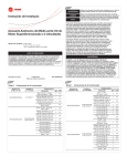
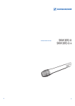
1
Industry Acoustic System
IAS-MO 2000 Set
Instructions for use
0
20
40
+/- 15dB
0
OVERLOAD
dB
GAIN
LEVEL
Contents
Safety instructions..................................................................................................... 2
IAS-MO 2000 Set ........................................................................................................ 4
Delivery includes......................................................................................................... 5
IAS-MO 2000 Set ................................................................................................. 5
MZWW 2000 ........................................................................................................ 5
Product overview IAS-MO 2000 Set........................................................................ 6
Putting the system into operation ......................................................................... 7
Setting up the device .......................................................................................... 7
Rack mounting ..................................................................................................... 7
Connecting the mains unit ................................................................................ 8
Connecting the amplifier ................................................................................... 8
Connecting the optical microphone ................................................................ 9
Switching the central unit on/off .................................................................. 11
Adjusting the sensitivity ................................................................................. 11
Overload indication ........................................................................................... 11
Disassembling the weather and wind protection .............................................. 12
Accessories................................................................................................................. 12
Care and maintenance............................................................................................. 13
Specifications ............................................................................................................ 14
Connector assignment ...................................................................................... 15
Frequency response curve ............................................................................... 15
Manufacturer Declarations ..................................................................................... 16
1
Safety instructions
This instruction manual contains important safety information.
Read this instruction manual.
Keep this instruction manual in a safe place. Always include this instruction
manual when passing the system on to third parties.
Heed all warnings.
Follow all instructions.
WARNING: To reduce the risk of fire or electric shock, do not expose the device
and the mains unit to rain or moisture.
Disconnect the mains connector from the wall socket to completely disconnect the device from the mains during lightning storms or when unused for
long periods of time.
Use only the supplied mains unit.
Ensure that the mains unit is:
– always readily operable and easily accessible,
– properly plugged into the wall socket,
– only operated within the permissible temperature range (see “Specifications” on page 14),
– not covered or exposed to direct sunlight for longer periods of time in
order to prevent heat accumulation.
Use of the MO 2000 CU central unit
OPTICAL MIC CENTRE UNIT
II (2) G [Ex op is T6 Gb] IIC
II (2) D [Ex op is Db]
TÜV 07 ATEX 553824
The MO 2000 CU central unit has been designed for use with the MO 2000 H
optical microphone.
To meet the requirement of the ATEX directive, the central unit must be
installed and operated outside areas with potentially explosive atmospheres!
Use of the MO 2000 H optical microphone
When installed in the MZWW 2000 weather and wind protection, the
MO 2000 H optical microphone meets the IP 54 standard for dust and moisture resistance. In combination with the MZWW 2000, the optical microphone
is approved and permitted for:
0044
y use in zone I explosive atmospheres
y use in potentially explosive atmospheres of group IIC and temperature class
T6.
Rack mounting
When installing the device in a closed or multi-rack assembly, please consider
that, during operation, the ambient temperature within the rack may significantly rise above room temperature. However, the ambient temperature
within the rack must not exceed the temperature limit specified in the specifications.
When installing the device in a rack, take good care not to affect the ventilation required for safe operation or provide additional ventilation.
Make sure the mechanical loading of the rack is even to avoid a hazardous
condition such as a severely unbalanced rack.
When installing the device in a closed or multi-rack assembly, please note
that intrinsically harmless leakage currents of the individual devices may
accumulate, thereby exceeding the allowable limit value. As a remedy,
ground the rack via an additional ground connection.
2
Operation
This device must be operated only from the type of power supply indicated
on the type plate. Observe correct polarity!
Never push objects of any kind through openings of this device as they may
touch dangerous voltage points or short-out parts that could result in fire or
electric shock.
Ensure sufficient ventilation. Do not block any ventilation openings. Install in
accordance with the manufacturer’s instructions.
Do not install near any heat sources such as central heating radiators, electric
heaters, stoves, or other devices that produce heat (e.g. amplifiers). Keep the
device away from direct sunlight and similar sources of heat.
Only use attachments/accessories specified by Sennheiser.
Use the device in dry rooms only. Do not expose the device to dripping or
splashing and ensure that no objects filled with liquids, such as vases or
coffee cups, are placed on the device. Do not use the device near water or
liquids.
Should a spillage occur, unplug the device and have it checked by a technician.
Service
No user serviceable parts inside! Do not attempt to service devices yourself as
opening or removing covers may expose dangerous voltage or other hazards.
If devices are opened by customers in breach of this instruction, the warranty
becomes null and void.
Refer all servicing to qualified service personnel. Servicing is required if a
device has been damaged in any way, such as mains cable or plug damage,
liquid has been spilled, objects have fallen inside, the device has been
exposed to rain or moisture, does not operate properly or has been dropped.
Intended use of the device
“Intended use” means that the device should be used within the operating
conditions and limitations described in this instruction manual.
“Improper use” means using the device other than as described in this
instruction manual, or under operating conditions which differ from those
described herein.
3
IAS-MO 2000 SET
The IAS-MO 2000 Set system consists of the following main components:
y 1 MO 2000 Set optical microphone system
y 1 MZWW 2000 weather and wind protection
The IAS-MO 2000 Set system meets the requirements of the ATEX directive.
The MO 2000 H optical microphone consists of an opto-acoustic microphone
head which is fitted with a fixed 3 m double fiber optic cable. The fiber optic
cable is connected to the MO 2000 CU central unit. Power is supplied via an
external wide voltage range power supply unit.
The MO 2000 H is an omni-directional microphone designed for picking up airborne sound. The components of the MO 2000 H microphone head (outside
dimensions: 1/2 inch) are made of plastic suitable for permanent stationary
use in areas where aggressive substances (gases, salts, moisture) or radiation are present. All components of the MO 2000 H microphone head are
metal-free, including the fiber optic cable feed.
The main areas of application of the optical microphone are acoustic measurement and communication tasks in industrial environments and EMC-sensitive areas as well as medical magnetic resonance imaging and magnetoencephalographic measurement (MEG). Other applications are to be found in
the field of non-detectable acoustic surveillance.
4
Delivery includes
IAS-MO 2000 Set
y 1 MO 2000 H optical microphone with 3 m fiber optic cable
y 1 MO 2000 CU central unit
y 1 mains unit with different country adapters
y 1 GA 2 rack adapter
y 1 carrying case
y 1 instruction manual
Optical microphone
Fiber optic cable
MO 2000 CU
0
20
40
+/- 15dB
0
Mains unit
OVERLOAD
dB
GAIN
LEVEL
MZWW 2000
y 1 pipe
y 1 SCRJ-GOF socket (inside the MZWW 2000)
y 1 cover with gasket
y 1 plate/mounting frame
y 1 SCRJ-HCS socket (fiber optic connector set)
y 1 windshield basket
y 1 MZQ 2000 microphone clamp
Pipe
Windshield basket
Microphone clamp
Fiber optic connector set
(not preassembled)
5
Product overview IAS-MO 2000 Set
0
20
40
쐋
+/- 15dB
0
OVERLOAD
dB
GAIN
LEVEL
AF OUT
BAL/UNBAL
OPTICAL MIC
INPUT
DC IN
12V/150mA
LEV 6dBu MAX
Gain switch (coarse adjustment)
Level control (fine adjustment), with 0 dB mark
OVERLOAD LED
ON/OFF button
Cable grip for power supply DC cable
DC socket for connection of power supply unit (DC IN)
Audio output (AF OUT BAL), XLR-3M, balanced
Audio output (AF OUT UNBAL), BNC socket, unbalanced
Type plate
SC optical input for microphone
SC optical output for microphone
4
1
5
6
2
3
Optical microphone
SC duplex connector
Mains unit
US adapter
UK adapter
EU adapter (preassembled)
Fiber optic connector
6
7
Putting the system into operation
CAUTION!
Risk of staining of furniture surfaces!
Some furniture surfaces have been treated with varnish, polish
or synthetics which might cause stains when they come into
contact with other synthetics. Despite a thorough testing of
the synthetics used by us, we cannot rule out the possibility of
staining.
왘 Do not place the central unit on delicate furniture surfaces.
You can set up the device on an even surface or mount it into a 19” rack.
Note:
Do not fit the rubber feet when rack mounting the device.
Setting up the device
To ensure that the device cannot slip on the surface on which it is placed, fix
the supplied four self-adhesive soft rubber feet to the base of the device.
왘 Ensure that the base of the device is clean and free from grease before
fitting the rubber feet.
왘 Fix the rubber feet to the base of the device by peeling off the backing
paper and fitting them as shown.
Rack mounting
CAUTION!
Danger of heat damage!
When installing the device in a closed or multi-rack assembly,
please consider that, during operation, the temperature within
the rack may rise significantly.
왘 Make sure not to affect the ventilation required for safe
operation or provide additional ventilation.
CAUTION! Danger of electric shock!
When installing the device in a closed or multi-rack assembly,
please note that intrinsically harmless leakage currents of the
individual devices may accumulate, thereby exceeding the
allowable limit value.
왘 Ground the rack via an additional ground connection.
For mounting two central units into a 19” rack, you require the GA 2 rack
adapter. The GA 2 rack adapter consists of:
8
9
y 1 blanking plate 0
y 2 rack mount “ears” y 1 jointing plate y 2 blanking plugs for closing off unused BNC holes
y 12 recessed head screws M 3x6
A
y 2 recessed head screws M 6x10
7
To mount two central units into a rack:
9
왘 Place the two central units side by side upside-down onto a flat surface.
왘 Align the jointing plate over the holes in the bottom sides of the central
units.
왘 Secure the jointing plate to the central units using eight of the supplied
recessed head screws (M 3x6).
9
왘 Hook the two rack mount “ears” the front panels of the central units.
0
왘 Secure the rack mount “ears” to the central units using two of the supplied recessed head screws (M 3x6) respectively.
왘 Slide the central units into the 19” rack.
왘 Secure the rack mount “ears” to the rack.
To mount only one central unit into a rack:
왘 Hook the two rack mount “ears” to the front panel of the central unit.
8
9
왘 Secure the rack mount “ears” to the central unit using two of the supplied
recessed head screws (M 3x6) respectively.
9
A
왘 Secure the blanking plate to one of the rack mount “ears” using two
of the supplied recessed head screws (M 6x10).
왘 If you are not front mounting the BNC output connector, insert the two
blanking plugs into the holes of the blanking plate.
왘 Slide the central unit into the 19” rack.
왘 Secure the rack mount “ears” to the rack.
Connecting the mains unit
왘 Connect the supplied mains unit to the socket (DC IN). Use the cable
grip to secure the power supply DC cable.
AF OUT
BAL/UNBAL
DC IN
12V/150mA
왘 Connect the suitable adapter to the mains unit .
왘 Connect the mains unit to the mains.
The device switches on automatically.
LEV 6dBu MAX
Connecting the amplifier
AF OUT
BAL/UNBAL
DC IN
12V/150mA
LEV 6dBu MAX
8
The audio outputs are available as a balanced XLR-3M output and an
unbalanced BNC output , allowing you to simultaneously connect two
devices (amplifier, etc.). Both outputs deliver the same output voltage, are
short-circuit proof and decoupled from each other.
왘 Connect the amplifier/mixing console to the balanced XLR-3M output or the unbalanced BNC output .
For details on balanced or unbalanced connection, see “Connector assignment” on page 15.
Connecting the optical microphone
CAUTION! Risk of damage to fiber optic cable!
Fiber optic cable must not be bent like conventional cable!
왘 When installing fiber optic cable, make sure not to bend it
beyond a bend radius of 50 mm.
CAUTION! Signal loss!
A wrong polarity will reduce the signal strength.
왘 When connecting the microphone, please observe correct
polarity.
CAUTION! Liquids can damage the electronics!
Liquids entering the housing of the device can cause a shortcircuit and damage the electronics.
왘 For outdoor applications, use only a suitable cable together
with the supplied fiber optic connector .
왘 Before connecting the optical microphone, remove the protections caps
from the microphone connections and of the central unit. Keep the
protection caps in a safe place for reuse during transport or storage. They
protect the microphone connections against dirt.
OPTICAL MIC
INPUT
C
왘 Connect the duplex connector of the professionally ready-made cable to
the microphone connections and of the central unit. Please observe
the correct insertion direction of the connector. The duplex connector is
connected the correct way round when the label on the connector is
facing downwards as shown.
왘 Connect the fiber optic connector with the professionally ready-made
cable to the weather and windshield.
7
Note:
Make sure that at least 15 cm of the fiber optic cable, starting from the
radiation source, is outside the explosion-hazardous area.
9
Connecting the optical microphone to the weather and windshield
왘 Remove the windshield basket and open the flap in the pipe as shown.
왘 Remove the protection caps from the connectors of the fiber optic cable .
2
왘 Push down the plastic housing on an even base until the housing detaches
from the connectors with an audible click.
Note:
Use a solid, even and clean base (e.g. a sheet of paper) in order to not
damage the tips of the connectors.
왘 Pull the connectors of the fiber optic cable one after the other out of
the plastic housing.
2
왘 Remove the protection caps of the SCRJ-GOF socket inside the weather
and windshield.
왘 Observe correct polarity of the professionally ready-made cable, i.e. insert
the connectors of the fiber optic cable into the SCRJ-GOF socket so that
the polarizing keys point outward. When the connectors are inserted
correctly, the polarizing keys lock into place with an audible click (see diagram on page 9).
왘 Lay the remaining microphone cable around the microphone clamp.
Please note that fiber optic cable must not be bent like conventional cable.
Make sure not to bend it beyond a bend radius of 50 mm.
왘 Insert the optical microphone into the microphone clamp .
2
10
1
B
쐋
Switching the central unit on/off
After connection to the mains, the device switches on automatically and the
ON button lights up.
왘 Press the ON button to switch the MO 2000 CU central unit on or off.
Note:
If the power supply is interrupted for several seconds (e.g. due to a power
failure), the device switches on automatically even if it was switched off
before.
Adjusting the sensitivity
With the microphone connected and both the gain switch and the level
control ! set to 0 dB, the specified sensitivity (mV/Pa) is obtained.
왘 Use the gain switch to increase the output voltage level by 20 dB
(tenfold increase) or 40 dB (hundredfold increase).
0
20
40
+/- 15dB
0
OVERLOAD
dB
GAIN
LEVEL
왘 Use the level control ! to steplessly adjust the output voltage level
between –15 dB and +15 dB.
Overload indication
The OVERLOAD LED indicates both positive and negative voltage peaks.
If the OVERLOAD LED lights up:
0
20
40
왘 Use the gain control and/or the level control ! to reduce the output
voltage level so that the OVERLOAD LED no longer lights up.
+/- 15dB
0
OVERLOAD
dB
GAIN
LEVEL
쐋
11
Disassembling the weather and wind protection
1
2
2
3
7
4
6
5
Accessories
Cat.-No.
Accessory
009823
GA 2 rack adapter
525700
MO 2000 H optical microphone
525701
MO 2000 CU central unit
525702
Pipe
522170
SCRJ-GOF socket (inside the MZWW 2000)
522168
Cover with gasket
522169
Plate/mounting frame
522176
SCRJ-HCS socket (fiber optic connector set)
067510
Mains unit
524601
Windshield basket
502186
MZQ 2000 microphone clamp
511999
Carrying case with foam insert
516503
Instruction manual
12
Care and maintenance
WARNING! Danger to life!
Repairs to explosion-proof components are not allowed. If you
repair explosion-proof components yourself, this presents an
explosion hazard.
왘 Refer all repairs to the manufacturer.
CAUTION! Liquids can damage the electronics of the MO 2000 CU central
unit!
Liquids entering the housing of the device can cause a shortcircuit and damage the electronics.
왘 Keep all liquids far away from the device.
왘 Before cleaning, disconnect all devices from the mains.
WARNING! Explosion hazard!
When cleaning the weather and wind protection, electrostatic
charges can be generated.
왘 Use only a soft, slightly damp cloth to clean the weather and
wind protection.
왘 Do not use any solvent-containing products for cleaning.
To clean the MO 2000 CU central unit:
왘 Before cleaning, disconnect the device from the mains.
왘 Use a soft, dry cloth to clean the device.
To clean the MZWW 2000 weather and wind protection:
왘 Use a soft, slightly damp cloth to clean the weather and wind protection.
13
Specifications
MO 2000 CU central unit
Housing
Front panel connections and
controls
Rear panel connections and
controls
1
/2 19” metal housing
ON/OFF button with operation indicator,
OVERLOAD LED,
gain control (coarse adjustment),
level control (fine adjustment), with
0 dB mark
DC socket for connection of mains unit,
SC duplex input for microphone,
XLR socket, balanced
BNC socket
Power supply
mains unit with country adapter
100-240 V AC to 12 V DC, 5.4 W
Power consumption of CU
1.5 W at 12 V DC
Current consumption
120 mA
Gain
steplessly adjustable between +/–15 dB,
three settings: 0 dB, +20 dB, +40 dB
AF output level
15 mV/Pa (level control set to central
position, gain switch set to 0 dB)
Output impedance
approx. 330 Ω unbalanced/660 Ω balanced
Max. output level
1.55 V
Operating temperature range
0°C to +40°C
Storage temperature range
–20°C to +70°C
MO 2000 H optical microphone
Design
MO 2000 H microphone head with
3 m fiber optic cable
Pick-up pattern
omni-directional
Frequency response
20 Hz to 40 kHz (±6 dB)
Sensitivity
15 mV/Pa
S/N ratio at 1 Pa SPL
> 50 dB(A)
Max. SPL
134 dB
Operating temperature range
–10°C to +70°C
Storage temperature range
–20°C to +70°C
MO 2000 H optical microphone
together with MZWW 2000
complies with the IP 54 standard
14
Fiber optic extension cable (optional)
Interface
SC
Design
multimode 200/230 μm
Cable loss
approx. 3–4 dB per 100 m
Optical transducer (optional)
Interface
socket/socket
Design
type SC
Coupling losses
5–6 dB per coupling pair
AF cable
Design
balanced microphone cable with shielding
Connector assignment
+
2
1
3
XLR-3F connector, balanced
DC connector for mains unit
Frequency response curve
dB
20
15
10
5
0
-5
-10
-15
-20
-25
-30
20
50
100
200
500
1k
2k
5k
10k
20k
50k Hz
15
Manufacturer Declarations
Warranty
Sennheiser GmbH & Co. KG gives a warranty of 24 months on this product.
For the current warranty conditions, please visit our web site at
www.sennheiser.com or contact your Sennheiser partner.
CE Declaration of Conformity
0044
This equipment is in compliance with the essential requirements and other
relevant provisions of Directives 94/9/EC, 2004/108/EC, and 2006/95/EC.
The IAS MO 2000 Set microphone system complies with the requirements on
intrinsically safe optical radiation equipment according to EN 60079-0: 2004
and EN 60079-28:2007. The devices are accompanied by the type-examination certificates TÜV 07 ATEX 553824 and TÜV 07 ATEX 553825X.
Statements regarding FCC and industry Canada
This device complies with Part 15 of the FCC Rules and with RSS-210 of
Industry Canada. Operation is subject to the following two conditions: (1) this
device may not cause harmful interference, and (2) this device must accept
any interference received, including interference that may cause undesired
operation.
Changes or modifications made to this equipment not expressly approved by
Sennheiser electronic Corp. may void the FCC authorization to operate this
equipment.
16
Sennheiser electronic GmbH & Co. KG
Am Labor 1
30900 Wedemark, Germany
Phone +49 (5130) 600 0
Printed in Germany
Fax +49 (5130) 600 300
Publ. 08/08
www.sennheiser.com
524194/A01