1
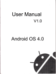
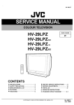
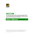
DR-1 Series H.264 Pentaplex Network DVR Quick Setup Guide* DR-116Q shown DR-104Q DR-108Q DR-116Q No. of Channels 4 8 16 Easy recording and setup. Remote LAN and Web viewing. iPhone/Smart phone compatible. Per-event recording and search. Pictures Per Second 120 240 240 BNC and VGA outputs. Programmable motion detection. Multi-channel audio recording. Free DDNS server. *For more installation tips, consult the User’s Manual on the CMS Software CD included with this product, or visit www.seco-larm.com. Note: Model numbers that end with “Q” or that have a round green “Q” sticker signify RoHS-compliant products. ENFORCER DR-1 Series DVR Quick Setup Guide Table of Contents: Parts List ....................................................... 2 Using the Mouse ........................................... 2 Front Panel ................................................... 3 Rear Panel .................................................... 4 Getting Started ........................................... 5-6 Connecting a PTZ Camera ........................... 7 Viewing ...................................................... 7-8 Recording ...................................................... 8 Searching .....................................................8-9 Remote Viewing .........................................9-10 Mobile Viewing .............................................. 10 Playback ........................................................ 11 Exporting Video ............................................. 11 Shutting Down the DVR ................................ 11 Pin Connection for Alarm I/O & RS-485 and Audio In ...................................................... 12 Parts List: DR-1 Series H.264 DVR ............................. x1 Power Adapter ............................................ x1 Quick Setup Guide* .................................... x1 IR Remote ................................................... x1 Warranty Card ............................................. x1 Power Cord ................................................. x1 *Soft User’s Manual* .............................................. x1 SATA Cable................................................... x1 CD with CMS Software Suite ........................ x1 D-Sub Connector (DR-104Q) ....................... x1 D-Sub Connector (DR-108Q, DR-116Q) ...... x2 copy also provided on CMS Software CD. Using the Mouse: OSD Location Main screen System menu Playback Desired Action Show channel fullscreen Show all channels Open main screen menu Select menu item / setting Cancel without saving (when item is selected) Go back / exit (when navigating a menu) Increase setting Decrease setting Show channel fullscreen Show all channels Scan forward one frame2 Scan backward one frame2 Increase playback speed3 Decrease playback speed3 Mouse Control Left click channel image Left click fullscreen image Right click Left click Right click Right click Scroll wheel up1 Scroll wheel down1 Left click channel image Use main screen menu Scroll wheel up1 Scroll wheel down1 Scroll wheel up1 Scroll wheel down1 1If scroll wheel is not available, please use the up/down arrows on the device front panel or remote control. must be paused to use this function. 3For details see the Playback secion on page 11 of this guide. 2Playback 2 SECO-LARM U.S.A., Inc ENFORCER DR-1 Series DVR Quick Setup Guide Front Panel: 1 2 3 4 ENFORCER® DOME 16 Channel 2 3 4 5 6 7 8 9 10 11 12 13 14 15 16 6 7 IR IRIS OPEN FOCUS (+) 18 DR-116Q shown. H. 2 6 4 16 Channel ESC MODE SEQ EZ COPY PLAY/STOP FREEZE Multi-functional Keypad 8 TELE PTZ 1 5 REC IRIS CLOSE FOCUS (-) MENU SEARCH ZOOM/ ENTER WIDE 17 15 13 11 16 14 12 10 9 Front panel feature descriptions: 1 Channel selection buttons 2 3 4 5 6 7 Power LED Alarm LED Network LED Record LED IR sensor Escape 8 Arrow buttons 9 Zoom/Enter 10 Menu/Tele 11 Search/Wide 12 Seq/Focus (+) 13 Freeze/Focus (-) 14 Mode/Iris Open 15 16 17 18 Play/Stop / Iris Close Dome EZ Copy USB 2.0 Port 1. Press any button to view the corresponding channel in full mode on the main screen. Press MODE (14) to return to other views. 2. Channel selection keys are used as a keypad to input numbers when entering passwords, etc. 3. In PTZ Mode, press Channel 1 to enter the Set/Go preset menu. Press Channel 2 to show or hide the PTZ settings menu. ON when DVR power is on. ON during any alarm event. ON when the Ethernet connection is transmitting. ON when recording is in progress. Receives commands from the IR Remote. Cancels the current operation or returns to the previous menu or screen. 1. Moves the viewable screen area when using zoom. 2. Moves the cursor when navigating menus. 1. Toggles 2x Zoom ON/OFF for present/last channel when viewing the main screen. 2. Chooses the selected menu or confirms the present setting. 1. Enters the system menu. 2. PTZ function: Zooms in to enlarge a certain area. 1. Opens the search menu to search for recorded video by date/time or event. 2. PTZ function: Zooms out to show a larger area. 1. Activates the Sequence feature when viewing the main screen. 2. PTZ function: Changes focus to a closer point. 1. Freezes the current view when viewing the main screen. 2. PTZ function: Changes focus to a farther point. 1. Selects full-screen or multiple-window display. 2. PTZ Function: Opens camera iris. 1. Plays or stops the video when viewing recorded material. 2. PTZ Function: Closes camera iris. Enters PTZ control mode. Marks start and end time when exporting video. Provides connection point for USB flash drive, mouse, or other USB device. SECO-LARM U.S.A., Inc 3 ENFORCER DR-1 Series DVR Quick Setup Guide Rear Panel: DR-104Q: 1 3 5 2 4 9 11 12 10 6 DR-108Q / DR-116Q: (DR-116Q shown) 3 1 10 8 7 4 6 5 2 9 11 12 Rear panel feature descriptions: 1 LAN 10/100M (RJ-45) 2 PS2-Compatible USB Port 3 4 5 6 4 VGA Output Alarm I/O Input Video Out / Main Monitor Audio Out/ Main Audio Use a Cat5e/6 cable to connect the DVR to a Local Area Network for remote access. Provides connection point for a PS2-compatible USB mouse. Note: PS2-compatible USB port does not support USB mice, flash drives, or other USB devices. Allows the DVR to output to a computer monitor or other VGA device. Allows the DVR to connect to alarm I/O and other RS-485 devices. Allows the DVR to output a video signal to a security monitor using a coaxial cable. Allows the DVR to output an audio signal to an audio device using an RCA cable. Video Input Allows the DVR to output a video signal to a secondary monitor using a coaxial cable. (DR-108Q and DR-116Q) Allows the DVR to output an audio signal to a secondary audio input device using an RCA cable. (DR-108Q and DR-116Q) Provides a connection point for video streams from cameras using coaxial cables. 10 Audio Input Provides a connection point for audio sources. 11 Power Jack Connect a 12VDC power source. 12 Ground Screw 7 Call Monitor 8 Call Audio 9 Connect to earth ground to prevent electrical damage to DVR. SECO-LARM U.S.A., Inc ENFORCER DR-1 Series DVR Quick Setup Guide Getting Started: Connections: 1. Connect cameras to the BNC channel inputs on the rear of the device. 2. Connect a VGA-capable display to the VGA port on the rear of the device. 3. If connection to a Call Monitor is desired, connect via the BNC port marked Call Monitor Out on the rear of the device. 4. If network access to the DVR is desired, connect the DVR to a Local Area Network (LAN) using a Cat5e/6 cable with an RJ-45 connector. 5. If using a mouse to operate the DVR On-Screen Display, connect a standard USB mouse via the USB port on the front of the device. For PS2-compatible USB mice, connect to the PS2-compatible USB port on the rear of the device. 6. When all connections have been made, plug the included power adapter into a 110~240 VAC power outlet. Connect the adapter to the power input on the rear of the device. Note: To avoid possibility of data loss, never unplug the adapter before properly shutting down the device. For more information see the section Shutting Down the DVR on page 11. Initial System Setup: 1. To enter the system menu, press MENU on the device’s front panel or remote control, or if using a mouse, right click when viewing the main screen and select the Menu icon . 2. Enter the administrator username and password. IMPORTANT: FOR SECURITY PURPOSES, CHANGE THE PASSWORD IMMEDIATELY AFTER ENTERING THE MENU FOR THE FIRST TIME. FAILURE TO DO SO MAY SERIOUSLY COMPROMISE THE SECURITY OF THE SYSTEM. Note: Default username: admin Default password: 1234. Note: Username is case sensitive. 3. To change the system password: a. Enter the system menu following steps 1 and 2 above. b. Select the System Setup icon using the left/right buttons and press ENTER, or use a mouse to left click the icon. c. Select User Management. d. For the first account, “admin”, select Edit in the column marked PWD. Enter a new 4~8 digit password. Note: admin account ID cannot be changed. Choose a password that is memorable but not easily guessed by others. e. For the second account, “user”, select Edit in the column marked ID. Enter a new name, if desired. When finished select OK. Next, select Edit in the column marked PWD. Enter a new 4~8 digit password as described in part d. above. f. By default there are only two user accounts active. If other accounts are added, be sure to change the password to ensure the security of the system. See the User’s Manual section 3.2.1 User Management for details on how to add and edit user accounts. SECO-LARM U.S.A., Inc 5 ENFORCER DR-1 Series DVR Quick Setup Guide Continued from page 5 4. To adjust the time and date: Note: Changes to time and date settings may cause inconsistency or data loss in previously recorded material. Back up all data before making changes. For more information on how to back up data, please see Exporting Video on pg. 11 of this guide. a. Enter the system menu and select System Setup . b. Select Date/Time. c. Select Date. The year will flash. Press the up/down arrows on the device front panel or remote control, or scroll up and down with the mouse scroll wheel. Repeat for month and day settings. d. Select Time. Adjust the time in the same manner as described in part c. above. e. Select Time Zone. Adjust the time difference to match the UTC (Coordinated Universal Time) offset in your area. For example, Los Angeles is 8 hours behind UTC, so the UTC offset is -8:00. f. For other features such as Daylight Saving Time and Network Time Protocol please see the User’s Manual section 3.4 System Date / Time Setting. 5. To adjust the system language: a. Enter the system menu and select System Setup . b. Select Language. Press the up/down arrows on the device front panel or remote control, or scroll up and down with the mouse scroll wheel. The language will change immediately. Press ENTER or left click to confirm your selection, or press ESC or right click to keep the previous language setting. There are 23 different language options. Basic Network Setup: 1. Enter the system menu and select System Setup . Be sure the DVR is connected to a network via an Ethernet cable. 2. Select Network Setup. a. Select LAN Select. If the DVR connects to a local area network, choose LAN (default). b. If the DVR connects directly to the internet, choose PPPoE. PPPoE users must configure the following options: PPPoE Account, PPPoE Password, and PPPoE Max Idle. c. If a connection to a network is not desired, choose None. The DVR will still record data. d. If a connection to a network is desired, it may be necessary to adjust LAN settings via the LAN Setup menu (Network SetupLAN Setup). Contact your network administrator for details about your network. e. To connect to a network based on DHCP, set the DHCP to ON. The IP address, Netmask, Gateway, and DNS setting will be retrieved from network servers. f. For non-DHCP users, set DHCP to OFF. Enter an IP address, Netmask, Gateway, and DNS settings. This information may be obtained from the network service provider. 3. Press ENTER or left click to confirm your selections, or press ESC or right click to cancel. 6 SECO-LARM U.S.A., Inc ENFORCER DR-1 Series DVR Quick Setup Guide Connecting a PTZ (Pan / Tilt / Zoom) Camera Note: For pin configurations, please see Pin Connection for Alarm I/O & RS-485 and Audio In on page 12 of this guide. 1. Make sure the RS-485 connector from the PTZ camera is configured correctly. See pg. 12. 2. Connect the PTZ camera’s RS-485 cable to the DVR’s Alarm I/O input. 3. Press MENU to access the OSD main menu and select Camera Setup. a. Select Dome Protocol to choose the corresponding protocol. b. Select Dome ID to choose an ID number. The ID number must match the ID address defined by the PTZ camera. 4. Select System Setup from the OSD main menu, and then select RS485 Setup to configure the RS-485 parameters. 5. For instructions on how to control the PTZ camera’s functions, please see the User’s Manual section 4.5 Dome Control. Viewing: The main screen shows live data from cameras connected to the DVR. 1. Display Modes—when viewing the main screen, scan through the modes by pressing the MODE button on the front panel/remote. Using the mouse, right click when viewing the main screen and choose . See each mode description below for further instructions. a. Full screen—shows one channel. Access this view by pressing a channel button on the front panel/remote, or left clicking any channel image (left click to return to all-channel view). b. Tile 2x2—Channels 1~4 will display first, followed by 5~8, 9~12 and 13~16. Using the mouse, right click the main screen and choose . Repeat to choose the next set of channels. (No. of channels available depends of the model). c. Tile 3x3 (DR-108Q and DR-116Q only)—DR-108Q will display all channels 1~8. DR-116Q will display channels 1~9 first, followed by 8~16. Using the mouse, right click the main screen and choose . Repeat to choose the next set of channels. d. Tile 4x4 (DR-116Q)—shows all 16 channels. Using the mouse, right click the main screen and choose . e. Sequence—DVR will automatically cycle through the channels. i. Press the SEQ button on the front panel/remote. Using the mouse, right click the main screen and choose . ii. The DVR will scan through all channels using the current display mode. For example, in the Full Screen mode, the DVR will scan through each channel in full screen. In Tile 4x4 mode, the DVR will scan through channels, displaying 4 at a time (1~4, 5~8, etc). 2. Freeze—freezes images on the present screen. From the main screen, press FREEZE on the front panel/remote. Using the mouse, right click the main screen and choose . 3. Quick Zoom—zooms the screen 2x. a. When viewing the main screen press ENTER on the front panel/remote. Using the mouse, right click the main screen and choose . Press ENTER or right click to zoom out. SECO-LARM U.S.A., Inc 7 ENFORCER DR-1 Series DVR Quick Setup Guide Continued from page 7 b. For Full Screen mode, present channel will zoom. For other modes, the last selected channel will zoom. c. Pan up/down/left/right using the front panel/remote or onscreen (for mouse) arrow buttons. 4. Certain icons will appear on screen while in any display mode. Please refer to the following chart for descriptions: Icon Description On-Screen Position The DVR is in playback mode. Lower left-hand corner A user is not logged in. Upper right-hand corner The number displayed is the user’s authority level. Upper right-hand corner The DVR is key locked. Bottom and centered Recording: By default, the DVR will record any data received from cameras connected to it. The following provides instructions for making basic adjustments to the record settings. See the User’s Manual section 3.5 Record Schedule / Quality Settings for more details. 1. Enter the system menu by pressing MENU on the front panel/remote or by right clicking the main screen and choosing . Enter a username and password if necessary. User account must have sufficient system authority to adjust recording settings. See the User’s Manual section 3.2.1 User Management for details on how to edit user accounts. 2. Choose Record Setup . The default setting is PresetBest Quality. 3. The recording options are: Extended Best Quality Standard 128Kbps DSL 256Kbps DSL 512Kbps DSL ezRecord Event Only OFF 4Pictures 720x480@30PPS4 (6KB/P5), 720x240@60PPS4 (4KB/P5), 360x240@120PPS4 (2KB/P5) 720x480@30PPS4 (22KB/P5), 720x240@60PPS4 (12KB/P5), 360x240@120PPS4 (6KB/P5) 720x480@30PPS4 (14KB/P5), 720x240@60PPS4 (8KB/P5), 360x240@120PPS4 (4KB/P5) 2KB/P5 3KB/P5 4KB/P5 Activates ezRecord function and ezRecord menu (Record Setup option 5) Activates event-only recording. DVR will record only when an event is detected. Disables presets. Use this setting when Per Camera Config is required. Per Second 5Picture 4. To configure recording on a per camera basis, set Preset Config to OFF. Each channel can be configured to record at a certain quality for certain time periods or events. For detailed information please see the User’s Manual section 3.5.4 Per Camera Configuration. Searching 1. To search playback data, press the SEARCH button on the front panel or remote, or right click the main screen and choose . 2. There are three different search modes from which to choose: Search by Time Select From: to start playing from earliest recorded video. 8 SECO-LARM U.S.A., Inc ENFORCER DR-1 Series DVR Quick Setup Guide Continued from page 8 Select End: to start playing from latest recorded video. At Select, choose a date and time to from which to start playing video. Select or click the play icon to begin playback from the selected start point. Calendar Search Select Calendar Search from the SEARCH menu. Choose the year and month you wish to view. Choose a day on the calendar and press ENTER. Days shown in light gray on the calendar are those for which recorded data is available. Press right/left keys to choose a playback start point or choose Select to manually choose a start time. Times where data was recorded will show in yellow in the Search By Time section. Select or click the play icon to begin playback from the selected start point. Search by Event Select the channel or channels you wish to view. Events from the selected channel or channels will be listed. Select an event record. Note: The event list will only display 1,024 events. Events are added on a first-in first-out basis. For more information about setting up event recording, please refer to the User’s Manual section 3.6 Event Settings. Remote Viewing: The DVR provides full access to live and recorded data, DVR settings, and export features via the Windows Internet Explorer Internet browser. 1. Ensure the DVR is connected to the local area network. Note the DVR’s IP address via System MenuSystem SetupLAN SetupIP. If using other network options see the User’s Manual section 5 Remote Monitoring Software or consult your network’s administrator. 2. On a computer with access to the local area network, open Internet Explorer and enter the DVR IP address in the following format (where w.x.y.z is the IP address as noted in step 1): http://w.x.y.z/ Note: When entering the IP address, enter exactly as shown in LAN Setup. Note: The default port used is 80. If changed, be sure to add it after the IP. For example: http://w.x.y.z:81/ where 81 is the new port number. 3. The browser will load the remote viewing software and prompt for a username and password. 4. The first time the software loads, two ActiveX controls will be installed. 5. Usernames and passwords are the same as those for accessing the DVR on screen display. Note: Your browser may require additional setup. If the remote viewing software does not load, please consult the User’s Manual section 5 Remote Monitoring Software. 6. The remote playback interface is as shown on the following page. SECO-LARM U.S.A., Inc 9 ENFORCER DR-1 Series DVR Quick Setup Guide Continued from page 9 Ch1 Ch2 Ch3 Ch4 Remote™ 2 1 2010/05/01 PM 12:00:00 Ch5 Ch6 Ch7 Ch8 Ch9 Ch10 Ch11 Ch12 8 3 4 5 6 7 1 3 5 7 9 11 13 15 High Speed 10 Ch13 11 Ch14 12 Ch15 13 9 Ch16 17 15 2 4 6 8 10 12 14 16 19 4:3 100% 14 16 Remote Viewing Software Interface Descriptions 1 Channel images with channel numbers 2 Current date and time 3 Sound ON/OFF 4 Quick Record (press once to assign file and start recording, press again to stop recording) 5 4-channel view 6 9-channel view 7 16-channel view 8 Channel selection (shows fullscreen view) 9 Bandwidth selection 10 Dual streaming 18 11 12 13 14 Screen size Download DVR Player software Live View (show live video streams) Playback (opens playback menu) 15 16 17 18 19 Settings (opens settings menu) Search by event Snapshot (captures current view) Show 4:3 aspect ratio Device status Mobile Viewing: If the DVR is connected to the Internet, mobile devices with Java-capable Internet browsers (including the iPhone) can be used to view live data. 1. In the mobile device web browser, enter the IP address of the DVR. Consult your network administrator for further information. 2. A window will display requesting a username and password. These are the same as those used to access the DVR via other means. 3. Once connected, a live stream from Channel 1 will be displayed along with the date and time. 4. Use the drop-down menu to select streams from other channels. 5. Be sure to log out when finished viewing to allow the next user to log in. 6. For more detailed instructions, see User’s Manual section 6 iPhone and Smart Phone Monitoring. 10 SECO-LARM U.S.A., Inc ENFORCER DR-1 Series DVR Quick Setup Guide Playback: 1. Playback is stopped and started by pressing the PLAY/STOP button on the front panel or remote, or by right clicking the main screen and choosing . 2. Playback will start from wherever the previously displayed recording was stopped. 3. Use the MODE, PLAY/STOP, FREEZE and ZOOM buttons to adjust playback. Using the mouse, right click and select , , or respectively. 4. When playback is paused, pressing the right/left buttons will advance/reverse by one frame. Using the mouse, scrolling up or down will advance/reverse respectively. 5. Change the playback speed using the right/left arrow buttons or scroll up and down with a mouse. Playback can be sped up or slowed down by up to 32x its original speed. Current playback speed is displayed in the lower left-hand corner of the screen. 6. To return to live view, press PLAY/STOP. Note: The system menu cannot be accessed while in Play or Freeze mode. First return to live view to access the system menu. Exporting Video: The DR-1 series offers a fast, simple and convenient export function. 1. Connect a USB flash drive or other storage device via the USB port on the front of the DVR. 2. Play back the desired recorded data. Mark the export start point by pressing the COPY button on the front panel or remote, or right click the main screen and choosing C . 3. Continue playback until you reach the desired end point. If needed, increase playback speed as explained in Playback on page 11 of this guide. Mark the export end point by pressing the COPY button on the front panel or remote, or right click the main screen and choosing C . 4. The DVR will prompt the user to confirm the data for export. Export may take up to an hour. 5. Data exported is in .drv format and can be viewed using the built-in remote viewing software. Please refer to the User’s Manual. Note: A copy of the video player software will be added to the export device. Shutting Down the DVR: 1. Enter the system menu by pressing MENU on the front panel/remote or right clicking the main screen and choosing . 2. Enter the Shutdown menu and choose Power Off, or use a mouse to click Execute. SECO-LARM U.S.A., Inc 11 ENFORCER DR-1 Series DVR Quick Setup Guide Pin Connection for Alarm I/O & RS-485, and Audio In: Alarm I/O & RS-485: DR-104Q: Pin 1 2 3 4 Connection Alarm Out Open Alarm Out COM RS-485 D+ RS-485 D- Pin 5 6 7 8 Connection Alarm In 1 Alarm In 2 Alarm In 3 Alarm In 4 Pin 9 10 11 12 Connection Alarm Out Close GND GND GND Pin 13 14 15 Connection GND GND GND DR-108Q and DR-116Q: Pin 1 2 3 4 5 6 7 8 9 Connection Alarm Out Open Alarm Out COM RS-485 D+ RS-485 DReserved Alarm In 1 Alarm In 2 Alarm In 3 Alarm In 4 Pin 10 11 12 13 14 15 16 17 18 Connection Alarm In 5 Alarm In 6 Alarm In 7 Alarm In 8 Alarm Out Close Reserved Reserved Reserved Alarm In 9 (DR-116Q) Pin 19 20 21 22 23 24 25 Connection Alarm In 10 (DR-116Q) Alarm In 11 (DR-116Q) Alarm In 12 (DR-116Q) Alarm In 13 (DR-116Q) Alarm In 14 (DR-116Q) Alarm In 15 (DR-116Q) Alarm In 16 (DR-116Q) Audio In (DR-108Q and DR-116Q only): Pin 1 2 3 4 5 6 7 8 9 Connection Audio 1 Audio 3 Audio 5 Audio 7 Audio 9 (DR-116Q) Audio 11 (DR-116Q Audio 13 (DR-116Q) Audio 15 (DR-116Q) GND Pin 10 11 12 13 14 15 16 17 18 Connection GND GND GND Reserved Audio 2 Audio 4 Audio 6 Audio 8 Audio 10 (DR-116Q) Pin 19 20 21 22 23 24 25 Connection Audio 12 (DR-116Q) Audio 14 (DR-116Q) Audio 16 (DR-116Q) GND GND GND Reserved IMPORTANT: Users and installers of this product are responsible for ensuring this product complies with all national, state, and local laws and statutes related to monitoring and recording audio and video signals. SECO-LARM will not be held responsible for the use of this product in violation of any current laws or statutes. WARRANTY: This SECO-LARM DVR is warranted against defects in material and workmanship while used in normal service for a period of three (3) years from the date of sale to the original consumer customer. SECO-LARM’s obligation is limited to the repair or replacement of any defective part if the unit is returned, transportation prepaid, to SECO-LARM. For full warranty information, please refer to the warranty card included with this product. NOTICE The information and specifications printed in this guide are current at the time of publication. However, the SECO-LARM policy is one of continual development and improvement. For this reason, SECO-LARM reserves the right to change specifications without notice. SECO-LARM is also not responsible for misprints or typographical errors. Copyright © 2010 SECO-LARM U.S.A., Inc. All rights reserved. This material may not be reproduced or copied, in whole or in part, without the written permission of SECO-LARM. SECO-LARM U.S.A., Inc. 16842 Millikan Avenue, Irvine, CA 92606 Tel: 800-662-0800/ 949-261-2999 Fax: 949-261-7326 12 Website: www.seco-larm.com E-mail: [email protected] PIUDS1 mi-DR1_1005.docx SECO-LARM U.S.A., Inc