1
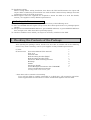
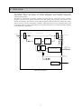
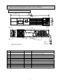
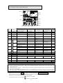
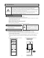
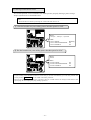
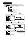
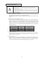
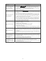
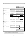
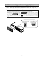
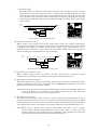
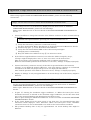
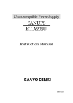
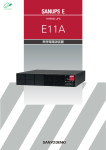
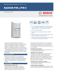
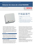
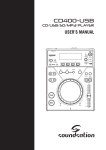
Uninterruptible Power Supply
SANUPS
E11A102A
Instruction Manual
M0007084E
Introduction
Thank you for choosing the SANUPS (E11A102A).
SAVE THESE INSTRUCTIONS
This manual contains important instructions for E11A102U001 that should be followed during installation and
maintenance of the UPS and batteries.To use the UPS correctly and safely, read this manual before using the
UPS. After reading, please keep it handy for convenient reference.
This UPS is intended for installation in a temperature-controlled indoor environment free of conductive
contaminants.
・ Operating temperature: 0 to 40゚C (32 to 104゚F)
UPS is an abbreviation for Uninterruptible Power Supply.
Table of contents
1. Safety Precautions -----------------------------------------------------------------------------------------------------------------------1
2. For Proper Operation -------------------------------------------------------------------------------------------------------------------6
2.1
2.2
2.3
2.4
Input Power Requirements-----------------------------------------------------------------------------------------6
Installation Precautions ---------------------------------------------------------------------------------------------6
Usage Precautions-----------------------------------------------------------------------------------------------------6
Dealing with Errors --------------------------------------------------------------------------------------------------7
3. Checking the Contents of the Package------------------------------------------------------------------------------------------7
4. Overview -------------------------------------------------------------------------------------------------------------------------------------8
5. External Dimensions and Part Names ------------------------------------------------------------------------------------------9
5.1 Front and Back Panels----------------------------------------------------------------------------------------------9
5.2 Control Panel and Indicators ----------------------------------------------------------------------------------- 10
5.3 External Interfaces-------------------------------------------------------------------------------------------------- 11
6. Installation -------------------------------------------------------------------------------------------------------------------------------- 12
6.1
6.2
6.3
6.4
6.5
6.6
6.7
Environment----------------------------------------------------------------------------------------------------------- 12
Transporting ----------------------------------------------------------------------------------------------------------- 12
Installation Space --------------------------------------------------------------------------------------------------- 12
Preparation Before Installation--------------------------------------------------------------------------------- 13
Attaching the Stand ------------------------------------------------------------------------------------------------ 14
Mounting a Rack Mount Type UPS -------------------------------------------------------------------------- 15
Inserting the Bushings -------------------------------------------------------------------------------------------- 15
7. Wiring--------------------------------------------------------------------------------------------------------------------------------------- 16
7.1 UPS Wiring------------------------------------------------------------------------------------------------------------ 16
7.2 External Interface Connections--------------------------------------------------------------------------------- 17
8. Preparations Before Operation ---------------------------------------------------------------------------------------------------- 18
9. Operating Procedures ----------------------------------------------------------------------------------------------------------------- 19
9.1
9.2
9.3
9.4
9.5
UPS Startup (Normal Operation) ----------------------------------------------------------------------------- 19
UPS Startup (Battery Power)----------------------------------------------------------------------------------- 20
Outage Simulation Test ------------------------------------------------------------------------------------------- 21
UPS Shutdown (Daily) -------------------------------------------------------------------------------------------- 22
UPS Shutdown (If Not to Be Used for More Than a Week) --------------------------------------- 22
10. User Settings --------------------------------------------------------------------------------------------------------------------------- 23
10.1 Setup Menu Item List ------------------------------------------------------------------------------------------- 23
10.2 Setup Menu Operations ----------------------------------------------------------------------------------------- 24
11. Maintenance and Inspection------------------------------------------------------------------------------------------------------ 25
11.1
11.2
11.3
11.4
11.5
11.6
11.7
Daily Inspection ---------------------------------------------------------------------------------------------------- 25
Periodic Inspection------------------------------------------------------------------------------------------------- 25
Parts Replacement------------------------------------------------------------------------------------------------- 25
Battery Maintenance---------------------------------------------------------------------------------------------- 26
Battery Test---------------------------------------------------------------------------------------------------------- 27
Battery Exchange -------------------------------------------------------------------------------------------------- 28
Bypass Fuse Exchange------------------------------------------------------------------------------------------- 30
12. Troubleshooting ------------------------------------------------------------------------------------------------------------------------ 31
13. Alarm Sounds -------------------------------------------------------------------------------------------------------------------------- 33
14. Maintenance Bypass Power Supply (Option) ------------------------------------------------------------------------------ 34
15. Functional Description -------------------------------------------------------------------------------------------------------------- 35
15.1
15.2
15.3
15.4
Basic Operation----------------------------------------------------------------------------------------------------- 35
Protective Functions ---------------------------------------------------------------------------------------------- 37
Protective Function Table--------------------------------------------------------------------------------------- 38
Specifications -------------------------------------------------------------------------------------------------------- 39
16. Warranty --------------------------------------------------------------------------------------------------------------------------------- 40
Appendix Usage notes for SANUPS SOFTWARE STANDALONE ------------------------------------------- 41
1. Safety Precautions
PRECAUTIONS
(IMPORTANT SAFETY INSTRUCTIONS)
Before installing, operating, performing maintenance or inspecting the UPS, be sure to read this manual and
accompanying documents carefully to obtain a clear understanding of the information related to its operation,
safety and important precautions.
This manual described two warning levels, DANGER and CAUTION, as described below.
!
DANGER
!
CAUTION
:Denotes immediate hazards which WILL probably cause severe bodily injury or death, as
a result incorrect operation.
:Denotes hazards which COULD cause bodily injury and product or property damage, as a
result incorrect operation.
Additionally, even those hazards denoted by
! CAUTION
△
could lead to a serious accident, so the instructions
should be strictly followed.
The following labels indicate particularly important instructions which must be carefully followed. The graphic
symbols indicate prohibited and mandatory actions
: Indicates actions that must not be allowed to occur (prohibited actions).
: Indicates actions that must be taken (mandatory actions).
− 1 −
1. Installation Precautions
! CAUTION
•
•
•
•
•
The UPS should be installed only by technically qualified personnel. Improper installation can result in
electric shock, bodily injury, and/or fire.
Never operate or store the UPS in the following environmental conditions. Doing so may cause the UPS to
malfunction, sustain damage or deteriorate, which could result in a fire.
a. In ambient environmental conditions other than those specified in the product brochure and instruction
manual (temperature 0 to 40°C (32 to 104゚F), relative humidity 20 to 90%), such as in extremely high or
low temperature and high humidity.
b. Where the UPS is exposed to direct sunlight.
c. Where the UPS is directly exposed to the heat from a heat source, such as a stove.
d. Where the UPS may be subject to vibration or physical shock.
e. Near a device that may emit sparks.
f. In the presence of dust, salt or corrosive or flammable gas.
g. Outdoors
If you mount the UPS in a rack, mount it in a rack that can be well ventilated, and be careful not to block
the air intake and exhaust vents of the rack and UPS. Do not allow the air intake or exhaust vents to be
obstructed. Keep the front and back of the UPS at least 20 cm away from the wall. If the air intake or
exhaust vent is blocked, the internal temperature of the UPS rises, which could cause battery deterioration
resulting in a fire. For maintenance, the UPS requires at least 1 m (39.4in) space at the front.
The space around the UPS and the rack must be ventilated. Unless the specified ventilation airflow (5 m3/h)
is maintained, gas produced by battery charging could result in rupture or explosion of the case.
Install the UPS on a stable surface capable of bearing the weight (16kg, 35.27 lbs) of the UPS in the
correct manner specified in this manual. If the UPS is installed incorrectly, impact or vibration could cause
it to fall or move inadvertently, resulting in bodily injury. Be careful to avoid back strain.
2. Wiring Precautions
! CAUTION
•
•
•
•
•
Wiring should be performed only by technically qualified personnel. Incorrect wiring can result in electric
shock and/or fire.
Protection in primary circuits against over currents, short circuits and earth faults is not provided inside
this UPS. Protection in primary circuit against over currents short circuits and earth faults shall be
providied as part of the building installation.
Connect the grounding cable securely in the manner specified. Failure to connect the grounding cable may
result in electric shock.
The grounding cables of all load devices* connected to the output of the UPS must be securely connected to
the grounding terminal. Failure to connect the grounding cables correctly may result in electric shock
The socket-outlet shall be installed near the equipment and shall be easily accessible.
* Load devices are devices such as computers that are connected to the UPS.
− 2 −
3. Operating Precautions
! DANGER
•
•
Immediately shut the UPS off if it malfunctions, or if an unusual odor or noise is observed. Failure to
do so may result in a fire.
To avoid electric shock, do not open the cover of the UPS.
! CAUTION
•
•
•
•
Risk of electric shock, do not remove cover, No user serviceable part inside. Refer serviving to qualified
personnel.
The space around the UPS must be well ventilated. Otherwise, gas produced by battery charging
could result in rupture or explosion of the case.
Before starting the UPS, make sure that the load side is safe. Be sure to refer to the instruction manual
while operating the UPS. The operating state of the UPS, as determined by the INV. ON/STAND BY switch
and the MAIN switch, is indicated by the LEDs as shown the table below.
The following table shows the UPS states resulting from operation of the MAIN SW and INV ON/STAND
BY switches. Check the indicators before and after operating. Do not touch the MAIN SW and INV
ON/STAND BY switches unless necessary. If power is supplied incorrectly, an electric shock or bodily
injury could result.
UPS Status
MAIN SW
OFF
ON
OFF
ON
•
•
•
INV ON/STAND BY
STAND BY
STAND BY
ON
ON
Power Output Status
LEDs
OUTPUT
Stopped
Stopped
INPUT (off-green),
INPUT (on-green),
Power supplied from inverter INPUT (blinking-green),
Power supplied from inverter INPUT (on-green),
OUTPUT (off-green)
OUTPUT (off-green)
OUTPUT (on-green)
OUTPUT (on-green)
Avoid inserting sharp objects or fingers into the fan. Doing so may result in bodily injury.
Do not touch the UPS, including the cables, if you hear thunder nearby. There is danger of electric shock
from a lightning strike.
Do not detach the cover of the options, except when you use some options. There is danger of electric shock
and equipment damage.
PROHIBITED
•
•
•
•
•
Never use the UPS for the following types of loads:
a. Medical instruments used for life support.
b. Control units for trains or elevators, failure of which could cause bodily injury.
c. Computer systems upon which social or public infrastructure depends.
d. Devices which serve applications related to the above.
Contact your sales representative if you need to use the UPS in an application like the above. Special
equipment, such as redundant devices or an emergency generator must be incorporated when operating,
maintaining and controlling systems in which a UPS is used with loads affecting life-support or public
infrastructure-dependent applications.
Do not smoke or use an open flame near the UPS, as it could cause the UPS to explode or rupture, resulting
in injury or fire.
Do not place containers of liquid, such as a flower vase, on the UPS. If the container was to spill, the liquid
could cause a short circuit, resulting in sparks or fire inside the UPS.
Do not sit, step or lean on the UPS, as bodily injury could result if the UPS was to fall.
Repairs and modifications to the UPS prohibited
All repairs and modifications to the UPS are prohibited. The UPS contains high voltage and no user
serviceable parts. Opening the cover, exchanging the battery, parts exchange, and repair can result in
electric shock and damage to the UPS when performed by anyone other than qualified service personnel. All
such repairs and modifications will void the warranty.
− 3 −
4. Radio Frequency Interference
!
•
CAUTION
This equipment has been tested and found to comply with the limits for a Class A digital device, pursuant to
part 15 of the FCC Rules. These limits are designed to provide reasonable protection against harmful
interference when the equipment is operated in a commercial environment. This equipment generates, uses,
and can radiate radio frequency energy and. if not installed and used in accordance with the instruction
manual, may cause harmful interference to radio communications. Operation of this equipment in the
residential area is likely to cause harmful interference in which case the user will be required to correct the
interference at his own expense.
5. Maintenance and Inspection Precautions
! CAUTION
•
•
•
•
•
•
Maintenance and repair of the inside of the UPS should be performed only by technically qualified
personnel. Electric shock, bodily injury and burns, fuming, or fire could otherwise result.
Contact your nearest sales representative or authorized service center to have the UPS checked out or to
replace defective parts. Opening the cover carelessly can result in an electric shock or burn.
Replace the batteries periodically (once every 4.5 years when operated at 25°C (77゚F)). Using batteries after
their service life has expired may cause a fire.
Never use organic chemicals such as gasoline, thinner, benzene or detergent to clean batteries. These can
cause the casing to crack and leak, resulting in fire.
Do not allow sharp metallic objects or fingers to touch the battery connectors of the UPS. Doing so may
result in an electric shock.
Do not touch any parts inside the UPS, even when AC input is removed. Voltage produced from the batteries
can still cause an electric shock.
6. Relocation and Transportation Precautions
! CAUTION
•
•
•
Be careful to avoid falling or dropping the UPS during relocation or transportation, as bodily injury could
result.
Be careful to avoid back strain when handling the UPS.
To avoid bodily injury caused by dropping the UPS, do not tilt it more than 10 degrees to either side when
moving it. Take preventative measures to avoid dropping the UPS if it must be tilted more than 10 degrees
when moving it.
− 4 −
7. Battery Handling Precautions
! CAUTION
•
•
•
•
•
•
•
•
•
•
•
•
Risk of explosion if battery is replaced by an incorrect type
Dispose of used batteries according to the instructions.
Battery servicing should be performed by technically qualified personnel. Keep unqualified personnel away
from batteries.
Replace batteries only with the same model and brand: HRL1234WF2FR manufactured by CSB BATTERY
Co., LTD.
Customers should not dispose of used batteries themselves. Contact your nearest sales representative,
authorized service center or sales office to dispose of used batteries.
Do not use batteries after their service life has expired. Doing so may result in fuming or fire. Additionally,
the battery backup function may fail to operate with such batteries, so that power will not supplied to the
load when a power outage occurs.
Batteries pose hazards for electrical shock and dangerous short-circuit current. The following precautions
should be observed when working with batteries:
a. Remove watches, rings and other metal objects.
b. Use insulated tools.
c. Wear rubber gloves and boots.
d. Do not lay tools or metal parts on top of batteries.
e. Disconnect the charging source prior to connecting or disconnecting battery terminals.
f. Determine whether the batteries have been inadvertently grounded, and if so, remove the source of
grounding. Contact with any part of a grounded battery can result in electric shock.
Do not attempt to open or disassemble batteries. The electrolyte is harmful to the skin and eyes. The battery
contains diluted sulfuric acid, which is extremely toxic. If a battery leaks, take appropriate measures to
prevent any battery fluid contacting your skin or clothing. Diluted sulfuric acid may cause blindness if it
gets into the eye, may burn skin upon contact. It is electrically conductive and corrosive. Observe the
following procedures if electrolyte spills:
a. Wear full eye protection and protective clothing.
b. If sulfuric acid contacts the skin, wash it off immediately with water.
c. If sulfuric acid contacts the eyes, flush thoroughly and immediately with water, and seek medical
attention.
d. Spilled sulfuric acid should be washed down with a suitable acid-neutralizing agent, such as a solution
of approximately one pound (500 grams) bicarbonate of soda in one gallon (4 liters) of water. The
bicarbonate of soda solution should be applied until evidence of reaction (foaming) has ceased. The
resulting liquid should be flushed with water and the area dried.
Lead acid batteries can present a risk of fire due to generation of hydrogen gas. The following procedures
should always be followed:
a. DO NOT SMOKE when near batteries.
b. DO NOT allow flames or sparks near batteries.
c. Before working with batteries, discharge static electricity from the body by first touching a grounded
metal surface before touching the batteries.
Do not dispose of batteries in fire, as they could explode.
If a fire occurs near a battery, do not use water to extinguish it. Use only a powder-distinguishing agent
(ABC). Using water can cause the fire to spread.
Strictly observe the following precautions when handling the batteries. Failure to do so may cause battery
leakage, overheating or explosion.
a. Do not solder to any part of the battery directly.
b. Do not charge the battery with reversed positive (+) and negative (-) terminal polarity.
c. Do not mix different battery types, brands or versions.
d. Do not attempt to peel off or break the outer covering of a battery.
e. Do not subject batteries to strong physical shock, or throw them away.
f. Clean batteries with water-moistened cloth squeezed hard. Do not use organic compounds such as
gasoline, thinner, benzene or detergent.
g. Electrical energy may remain in a battery even after its service life has expired.
Do not allows sparks near used batteries, and protect them from short-circuiting.
− 5 −
2. For Proper Operation
2.1 Input Power Requirements
(1) Make certain that the AC input voltage and frequency correspond to the specified equipment
rating (100V, 110V, 115V, 120V, within -20% and +15%, and 50 or 60 Hz ±5%: Active Filter
and Economy Mode*).
* The frequency variation range is set to ±3% when the UPS is shipped from the factory.
If the frequency variation range of input power supply is ±5%, select ±5% as described in item ③
“Frequency sync range” of 10.1 “Setup Menu Item List”. Because the frequency sync range is the same
for both input and output, an input frequency error occurs when the frequency sync range exceeds the
setting value, preventing the UPS from switching to active filter mode or economy mode operation.
(2) The current capacity of the AC power supply must satisfy the requirements of the UPS
(0.96 kVA or more). (Breaker capacity of 20 A or more is recommended.)
2.2 Installation Precautions
(1) Carefully consider the leakage current when a leakage circuit breaker is installed on the
input side. The maximum leakage current of the UPS is 3mA.
(2) Keep the UPS at least 1 m (about 40 inches) away from CRT displays. Other devices which
may be sensitive to magnetic flux should be kept away from the UPS, as it emits a slight
amount of magnetic flux.
(3) The UPS employs a fan for forced-air cooling. Provide at least 20 cm (about 8 inches)
clearance at the front and back of the UPS to permit free airflow at the air intake and
exhaust vents. Also, for maintenance purposes, a space of at least 1 m (about 40 inches) will
be needed at the front of the UPS and a space of at least 50 cm (about 20 inches) will be
needed at the back of the UPS.
When mounting the UPS in a rack, use a rack which allows ventilation and provide at least
20 cm (about 8 inches) clearance from the front and back of the rack to permit free airflow at
the air intake and exhaust vents. Also, for maintenance purposes, a space of at least 1 m
(about 40 inches) will be needed at the front of the rack, and a space of at least 50 cm (about
20 inches) will be needed at the back of the rack.
For details, see §6.3 “Installation Space”.
(4) When the AC input power is single-wire grounded, always connect the ground phase to the S
terminal (phase) side on the UPS.
(5) As far as possible, do not ground the output (load) side. If you must make a single-wire
grounded connection, always connect the ground phase to the V terminal (phase) side on the
UPS. (This is to prevent short-circuiting by the ground.)
2.3 Usage Precautions
(1) Never short-circuit the output terminals, or connect a load which draws short-circuit current.
Doing so causes protective functions to activate or fuses to open, preventing output.
(2) Unsuitable load devices
Do not connect laser printers, plain paper fax machines, copy machines, or overhead
projectors as load devices. Such devices typically include heating elements that draw high
current. This may cause an overload that could prevent battery backup operation when an
outage occurs, and could damage the UPS.
(3) Power supply environment
If the UPS is used in an environment subject to long and frequent power outages (more than
once a week), the batteries may not receive sufficient charge, which could result in
foreshortened battery life and premature battery failure.
(4) If the UPS is not operated for a long period, the batteries may require recharging. Operate
the UPS with no load to recharge the batteries as indicated in the following table, according
to the storage temperature. If the batteries in the UPS are left uncharged, their service life
will be greatly foreshortened.
Storage Temperature
25°C (77°F)
30°C (86°F)
40°C (104°F)
Charge Interval
Once every 6 months
Once every 4 months
Once every 2 months
− 6 −
No-Load Operation
At least 20 hours
At least 20 hours
At least 20 hours
(5) Insulation testing
Before testing indoor wiring insulation, shut down the UPS and disconnect the input and
output cables. Conducting an insulation test with the UPS connected may damage electronic
components such as the built-in arrester.
(6) Rack support rails (not supplied) are required to mount the UPS on a rack. For details,
contact your supplier or Sanyo Denki representative.
2.4 Dealing with Errors
Contact your supplier or Sanyo Denki representative if any of the following occur.
(1) The red ALARM indicator lights (except when the UPS stops because of a prolonged power
outage).
(2) The green INV.ON/STAND BY indicator, green INPUT indicator, or green OUTPUT indicator
does not light even when the UPS is operated properly.
(3) Another condition occurs which you suspect is caused by a failure in the UPS.
3. Checking the Contents of the Package
After opening the package carton, check to be sure that it contains all of the following
items. If any item is missing, contact your supplier or Sanyo Denki representative.
(1) UPS
(2) Accessories
Instruction Manual (this manual)
Fuse 15 A
Network cable
Rack mounting bracket (Right)
Rack mounting bracket (Left)
Screws for Rack mounting brackets
Bushings
Stands
Screws for Stands
Power Management Software disc (CD-ROM)
(SANUPS SOFTWARE STANDALONE)
1
1
1
1
1
1
4
6
2
4
1
including Install Guide and User guide
* Note about sale or transfer of ownership
If you sell the UPS or transfer ownership to a third party, all accessories and other
items supplied with the UPS must be sold or transferred together with the UPS.
− 7 −
4. Overview
The SANUPS E11A is a stationary-type uninterruptible power supply designed to provide
high-quality, stable AC power to critical equipment that requires continuous,
uninterrupted power.
The UPS is comprised of rectifier, charger, inverter, battery, and utility power transfer
(bypass) circuits. In the event of failure of the AC utility power source, AC output to the
load is sustained by the inverter converting DC power from the batteries. When the utility
power recovers, inverter operation continues while the batteries are recharged. The UPS
is therefore able to supply completely uninterrupted AC power to connected loads without
even momentary power loss.
B ypass Fu se
Bypass C ircuit
Filter
M AIN
SW
Filter
AC In pu t
F u se
Rectifier
AC O utpu t
Inverter
Charger
D C /D C
Con verter
CARD I/F
PC I/F
C on trol Circu it
F u se
<
Batteries
LA N I / F (option)
UPS Block Diagram
− 8 −
Extern al
Batteries
5. External Dimensions and Part Names
5.1 Front and Back Panels
③
440
17.32
② (Inside cover)
86
3.39
(Inside cover)
①
⑤
⑦
⑨
MAIN SW
EXT.
BATT
⑥
④
⑫
⑧
⑩
⑪
Length: 1.8 m
(70.9 inch)
Depth: 408 mm (16.06 inch)
Weight: 16 kg (35.27 lbs)
No.
Name
①
Control panel and indicators
②
③
④
⑤
⑥
⑦
⑧
⑨
⑩
⑪
⑫
Forced bypass switch
Battery connector
Card interface
PC interface
Exhaust vent
Option card slot
Input switch
Bypass fuse
Output terminals
Input power plug
External battery connector
Label
Function
Control panel for control operations, UPS status
-
display, and function settings
Forced Bypass Switch to bypass UPS during maintenance
-
Battery connector
CARD I/F
Connector for external signal transfer
PC I/F
Connector for external PC-WS signal transfer
-
Ventilation
OPTION CARD Option card slot
MAIN SW
Input power On and Off switch
BYPASS FUSE Fuse to protect bypass circuits
OUTPUT
Normal power output terminals
INPUT
Input power plug
EXT.BATT
Connector for external battery
− 9 −
5.2 Control Panel and Indicators
LED11
LED5
LED6
LED10
LED7
LED8
①
LED12
LED4
②
LED9
LED0
No.
LED2
LED3
LED4
LED5
LED6
LED7
LED8
LED9
LED10
①
LED11
②
③
LED3
Functions
Status display
Lit
Not lit
Input power status
Normal input
-
UPS output power status Inverter operation OFF
Economy mode
OFF (*3)
ECONOMY Operation mode
operation (*1)
Double conversion
DOUBLE
Operation mode
OFF (*3)
mode operation (*2)
CONVERSION
Battery power
BATT.LOW Battery status
Battery power low
normal
Load level 25%
Load 25% or more Load under 25%
Output voltage setting
25
Setting other than
-
100V (*4)
100V
50
75
100
Load level 50%
Output voltage setting
110V (*4)
Load level 75%
Output voltage setting
115V (*4)
Load level 100%
Output voltage setting
120V (*4)
Overload display
Alarm display
Load 50% or more
Load under 50%
Setting other than
-
110V
Load 75% or more Load under 75%
Setting other than
-
115V
Load 100% or more Load under 100%
Setting other than
-
120V
Load 105% or more Load under 105%
Failure detected
No failure
O.L.
ALARM
INV.ON
Inverter operation On/Off operation
STAND BY
INV.ON
Inverter operation status Inverter operation
STAND BY
Off
Slow blink
Input error
Bypass operation
-
-
Battery exhausted
-
100V setting
-
110V setting
-
115V setting
-
120V setting
-
-
Bypass operation
Fast
blink
-
-
-
-
-
-
-
-
-
-
-
-
-
-
-
-
BATT.TEST Battery test
LED12 BATT.TEST Battery test
③
LED2
INPUT
OUTPUT
LOADLEVEL(%)
LED0
LED1
Label
LED1
CLEAR
Result: Normal
-
Result: Error
Status:
Testing
Stop buzzer, clear result of battery test
※1. Economy mode operation・・・・When power conditions are good, UPS supplies this power to the load.
※2. Double conversion mode operation・・・・When power conditions fluctuate, UPS converts to the stable power, and
supplies to the load.
※3. Active Filter Mode operation・・・・When load power fluctuates. Suppresses high frequencies generated by the load
and improves power factor.
When the green DOUBLE CONVERSION and the green ECONOMY are both off, the UPS is in Active Filter Mode.
※4. The output voltage setting is displayed for about 5 seconds after the UPS is powered on (LED initialization display).
This manual uses a frame
to indicate switches. (Example: INV.ON/STAND BY ).
It also describes the color of the LED whenever it refers to an indicator on the control panel.
(Examples: Green INV.ON/STAND BY, red ALARM)
: Indicates a lit LED
In the illustrations in this manual
: Indicates a blinking LED
− 10 −
5.3 External Interfaces
①
UPS back panel
MAIN SW
EXT.
BATT
②
No.
Name
① PC I/F
(PC interface)
(RS-232C)
Function
Allows you to control the UPS from a computer (PC or workstation) by using the
supplied power management software. Install the power management software (*2)
on the computer, and connect the computer to the UPS with the supplied network
cable.
Interface mode (*1): Workstation mode
(*1): Use the controls on the front panel to set the interface mode. For more
information, see item ⑤ PC Interface mode in §10.1 “Setup Menu Item List”.
D-sub9-pin (male)
2
RXD
3
TXD
5
GND
4
DTR
6
DSR
8
CTS
7
RTS
①
②
③
④
⑤
⑥
⑦
⑧
⑨
Fixing screw
inch
(*2): For more information, refer to the User Guide in the CD-ROM of the
SANUPS SOFTWARE.
Allows you to connect an optional Sanyo LAN interface card.
② CARD I/F
(Card interface)
Interface mode (*1): Workstation mode
Note
This connector is for use with Sanyo option cards only.
Cannotbe
used with
other than
Sanyo
option cards.
5 (COM)
1 7V,1A/Option power
D-sub 9-pin (female)
⑨
⑧
⑦
⑥
⑤
④
③
②
①
2 RXD (in)
3 TXD (out)
Note
The CARD I/F and PC I/F connectors cannot be used at the same time.
− 11 −
Fixing screw
inch
6. Installation
!
CAUTION
・ When installing the UPS, carefully follow the instructions in this Instruction Manual.
・ Install the UPS on a stable surface that can bear the weight (16 kg, 35.27 lbs).
This surface should be flat, so the UPS cannot fall and cause bodily injury.
・ The possibility of vibration and shock should be minimized at the installation location.
・ All work that involves lifting the UPS, such as mounting it in a rack or attaching the
stand, should be carried out by at least 2 persons.
・ Be careful to avoid straining your lower back when mov