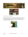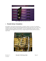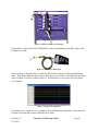
1
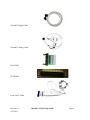
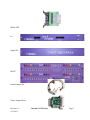
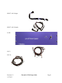
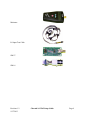
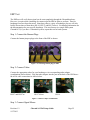
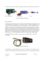
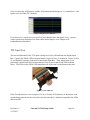
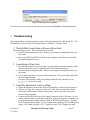
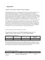
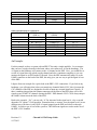
Cheetah16/32/64 Setup Guide Installation guide for the most common components of a Cheetah 16/32/64 system Neuralynx, Inc. 105 Commercial Drive, Bozeman, MT 59715 Phone 406.585.4542 • Fax 406.585.9034 www.Neuralynx.com Revision 1.2 9/17/2013 [email protected] Table of Contents 1 2 3 4 5 6 7 8 9 Document Overview ............................................................................................................... 4 Cheetah 16/32/64 Overview ................................................................................................... 4 Component Listing.................................................................................................................. 4 Component Images ................................................................................................................. 5 4.1 Hardware Mounting .....................................................................................................10 4.2 Computer Hardware .....................................................................................................13 Cheetah Hardware Cable Connection ................................................................................... 14 Cheetah Setup Completion ................................................................................................... 19 Testing................................................................................................................................... 20 Troubleshooting .................................................................................................................... 25 Appendix A ........................................................................................................................... 27 List of Figures and Tables Table 1 Common components for a Cheetah 16/32/64 system ...................................................... 4 Table 2 Standard Setup for a Cheetah 16...................................................................................... 27 Table 3 Standard Setup for a Cheetah 32...................................................................................... 27 Table 4 Standard Setup for a Cheetah 64...................................................................................... 28 Figure 5.1 Mounting hardware ..................................................................................................... 10 Figure 5.2 Mounting the ERP(s) ................................................................................................... 10 Figure 5.3 Mounting the Cheetah Digital Interface Box .............................................................. 11 Figure 5.4 Front of completed rack............................................................................................... 12 Figure 5.5 Back of completed rack ............................................................................................... 12 Figure 5.6 Computer hardware cards ............................................................................................ 13 Figure 5.7 Device Manager window ............................................................................................. 14 Figure 6.1 Attaching the power supply ......................................................................................... 15 Figure 6.2 PSC Power connection ................................................................................................ 15 Figure 6.3 ERP Power connection ................................................................................................ 16 Figure 6.4 Connecting the Amplifiers .......................................................................................... 16 Figure 6.5 Cable connection to DT3010 card ............................................................................... 17 Figure 6.6 ACP cable connection ................................................................................................. 18 Figure 6.7 ERP AICA cable JAMP# connection .......................................................................... 18 Figure 6.8 ERP AICA cable AMP# connection ........................................................................... 19 Figure 7.1 Completed Cheetah 32 System .................................................................................... 19 Figure 8.1 20 Pin L8 Input test connection ................................................................................... 21 Figure 8.2 Minirator to BNC input ............................................................................................... 21 Figure 8.3 Square wave input test ................................................................................................. 21 Figure 8.4 Connecting banana plugs to ERP ................................................................................ 22 Figure 8.5 Tether Adapter Combinations ..................................................................................... 22 Figure 8.6 Signal Mouse Combinations........................................................................................ 23 Revision 1.2 9/17/2013 Cheetah 16/32/62 Setup Guide Page 2 Figure 8.7 Minirator with BNC cable ........................................................................................... 23 Figure 8.8 Square wave ERP test.................................................................................................. 24 Figure 8.9 TTL Input test .............................................................................................................. 24 Figure 8.10 TTL Input Test Acquisition ....................................................................................... 25 Table 1 Common components for a Cheetah 16/32/64 system ...................................................... 4 Table 2 Standard Setup for a Cheetah 16...................................................................................... 27 Table 3 Standard Setup for a Cheetah 32...................................................................................... 27 Table 4 Standard Setup for a Cheetah 64...................................................................................... 28 Revision 1.2 9/17/2013 Cheetah 16/32/62 Setup Guide Page 3 1 Document Overview This document is intended as a setup guide for the most common components of a Cheetah16, Cheetah32 or Cheetah64 system. If your specific hardware configuration differs from the configuration described in this guide, please refer to the setup documentation for your specific hardware. If you are missing or have questions about obtaining any hardware mentioned in this document, please call either 406-585-4542 or email [email protected]. 2 Cheetah 16/32/64 Overview Using analog technology that has been field tested for years, the Cheetah 32 is a high quality, cost effective recording system for your low channel count applications. Its modular design allows for expansion from 16 to up to 32 channels of analog signal acquisition at 32KHz. Each Cheetah 32 also features a 16 bit, bidirectional TTL port, and the ability to output two analog signals. The Cheetah 32 works with the Cheetah Data Acquisition software to offer simple control of the acquisition system. Flexible data display and setup options as well as real-time experiment monitoring and control allow you to utilize your equipment to its fullest. You can even play back experiments after they have been recorded, and repeat your experiments with the test subject completely disconnected from the system. Neuralynx system configurations are designed to get your experiment running quickly and easily. Programmable Lynx-8 amplifiers provide low noise gain and filter control as well as subtraction of reference values. Manual reference selection, external signal input ports, and headstage power controls are provided by the 27 channel Electrode Reference Panel (ERP-27). The configuration packages also include all of the components and accessories that you’ll need to tie the system together. These base configurations can also be customized to suit the requirements of your particular experiment. 3 Component Listing Below is a listing of common components and quantities for a Cheetah16/32/64 system. Table 1 Common components for a Cheetah 16/32/64 system Part Number DT3010/32 Revision 1.2 9/17/2013 Description DT3010 PCI Card (Pre-installed in PC Quantity Cheetah16 Cheetah32 Cheetah64 1 1 2 Cheetah 16/32/62 Setup Guide Page 4 Cheetah32 Digital Cable Cheetah32 Analog Cable PIO34-LED PCI-DIO24 Lynx-8 ACP Cable PIO20-LED L8 Digital I/O ERP-27 Banana Jumper Set Tether Adapter Micro Stim Plug ERP-27-AICA Single ERP-27-AICA Double L8-PS PSC-5 PSC-10 AC Cable MIN L8 Input Test SM-27 SM-16 Cheetah32 Digital Cable 1 Cheetah32 Analog Cable 1 2 1 2 34 Pin LED Testing Board DIO24 PCI Card (Pre-installed in PC) Lynx-8 ACP Cable 20 Pin LED Testing Board Lynx-8 Amplifier Cheetah Digital Interface Box EEG Reference/Patch Panel (27 Channel) Banana Jumper Set Tether Adapter 1 1 1 1 1 1 1 1 2 1 1 1 1 4 1 1 2 1 8 1 2 1 1 1 1 2 2 Stimulus Plug Amplifier Input Cable Assembly (4 Connector) Amplifier Input Cable Assembly (8 Connector) Lyns-8 Power Supply Power Supply Cable (5 Connector) Power Supply Cable (10 Connector) Black 120V AC Power Cable Minirator L8 Amplifier Input Tester 27 Channel Signal Mouse Tester 16 Channel Signal Mouse Tester 1 1 1 1 2 1 1 1 1 1 1 1 1 1* 1 1 1* 1 1 1 1* 1 1 1 1 * NOTE: International customers must supply their own AC power cable. 4 Component Images DT3010/32 Revision 1.2 9/17/2013 Cheetah 16/32/62 Setup Guide Page 5 Cheetah32 Digital Cable Cheetah32 Analog Cable Pio34-LED PCI-DIO24 Lynx-8 ACP Cable Revision 1.2 9/17/2013 Cheetah 16/32/62 Setup Guide Page 6 PIO20-LED L8 Digital I/O ERP-27 Banana Jumper Set Tether Adapter Micro Revision 1.2 9/17/2013 Cheetah 16/32/62 Setup Guide Page 7 ERP-27 AICA Single ERP-27 AICA Double L8-PS PSC-5 PSC-10 Revision 1.2 9/17/2013 Cheetah 16/32/62 Setup Guide Page 8 Minirator L8 Input Test Cable SM-27 SM-16 Revision 1.2 9/17/2013 Cheetah 16/32/62 Setup Guide Page 9 4.1 Hardware Mounting The Cheetah hardware is designed to fit into a standard 19” rack mount system. It is assumed that you have purchased an appropriate rack and mounting hardware separately. It is highly recommended that the Cheetah equipment be rack mounted. Use of nylon washers between the mounting screws and the Neuralynx equipment faceplate will prevent scratching of the faceplate paint. If you do not have this equipment, please contact Neuralynx for information on obtaining rack mount hardware. Figure 4.1 Mounting hardware Step 1: Mount the ERP(s) The number of ERPs will vary depending on your Cheetah system. This diagram shows a Cheetah32 setup with one ERP. The ERP should be mounted at the top of the rack system. Figure 4.2 Mounting the ERP(s) Step 2: Mount the Lynx 8 Amplifiers The number of Lynx 8 amplifiers will vary depending on your Cheetah system. This diagram shows a Cheetah32 setup with four amplifiers. The Lynx 8 amplifiers should be mounted underneath the ERP, making sure to leave a small gap (noted below) between the ERP and top most Lynx 8 amplifier. This gap will be necessary for connecting the ERP to the amplifiers later on. No space is necessary between each amplifier, only between the topmost amplifier and the bottommost ERP. All amplifiers should have their Program switch in the Program position. Revision 1.2 9/17/2013 Cheetah 16/32/62 Setup Guide Page 10 NOTE: For the rest of this document, the bottom most amplifier will be referred to as amplifier 1 and the subsequent amplifiers will increment from bottom to top. Step 3: Mount the Cheetah Digital Interface Box The Cheetah Digital Interface box will be mounted directly beneath the bottommost Lynx 8 amplifier. Figure 4.3 Mounting the Cheetah Digital Interface Box Step 4: Mount the Lynx 8 Power Supply Revision 1.2 9/17/2013 Cheetah 16/32/62 Setup Guide Page 11 Mount the Lynx 8 Power Supply directly beneath the digital interface box using the rack mounting screws as shown. Mounting of the Cheetah hardware is now complete, below is a front and back image of a completed rack for a Cheetah32 system. Figure 4.4 Front of completed rack Figure 4.5 Back of completed rack Revision 1.2 9/17/2013 Cheetah 16/32/62 Setup Guide Page 12 4.2 Computer Hardware The computer hardware consists of the DIO 24 and DT3010 cards. The quantity of these cards is determined by your Cheetah system. These cards will be installed into your computer, properly setup and tested prior to shipping. If you did not purchase your computer from Neuralynx or you are adding a card to your system, please see the setup documentation for the card you wish to install. If you have purchased the Video Tracking option for your Cheetah system, one or two DT3120 cards will also be installed in your computer. Video Tracking hardware setup is not covered in this document; please see the setup documentation for the Video Tracking hardware for detailed setup instructions. If you have purchased your own PC, please note that these are PCI cards and will not work with PCI-X motherboards. Figure 4.6 Computer hardware cards You can verify the proper installation of the computer hardware by opening up the device manager on your pc and verifying that the highlighted devices pictured are installed and functioning properly. Revision 1.2 9/17/2013 Cheetah 16/32/62 Setup Guide Page 13 Figure 4.7 Device Manager window 5 Cheetah Hardware Cable Connection Cable connection is the most important part of the end user setup process. If the system is not cabled properly, it simply will not work. No error logs can be used to determine cabling issues, so please read this section carefully. NOTE: Make sure that your computer is turned OFF while making cable connections. Step 1: Lynx 8 Power Supply Cable Connection and Testing BEFORE CONNECTING ANY OF THE POWER CONNECTIONS MAKE SURE OF THE FOLLOWING: The ERP(s) are switched to OFF. The Lynx-8 power supply is switched to OFF. Begin by connecting black AC power cable to the Lynx 8 power supply and the wall socket. Verify that the power supply is rated for your country’s power system. This will be indicated on Revision 1.2 9/17/2013 Cheetah 16/32/62 Setup Guide Page 14 the back of the power supply above the fuse (see picture) Once the connection is made, turn ON the power supply and verify that the LEDs labeled +15 OK and -15 OK are green. Turn OFF the power supply. Figure 5.1 Attaching the power supply Next connect the PSC-5/10 cable to the back of the Lynx 8 power supply screws (labeled Power Output) as shown below. This should be done using a slotted (regular, flat head, etc.) screw driver. Make sure the cable colors (from left to right) are black (-15 B), green (Gnd G) and red (+15 R), and that they are fastened tightly. Figure 5.2 PSC Power connection Now connect the PSC five pin (three wire) connector to the ERP power connection (labeled +15 -15 Gnd) on the back of the ERP board. Turn ON the Power Supply, then turn ON the ERP. Verify that the power supply LEDs labeled +15 OK and -15 OK and the ERP LEDs labeled +V, -V, +I, and –I are all green. Turn OFF the ERP and then turn OFF the power supply. Revision 1.2 9/17/2013 Cheetah 16/32/62 Setup Guide Page 15 Figure 5.3 ERP Power connection Next we will connect amplifier 1. Plug one of the five pin (four wire) power connections to the port labeled Power GG_BR in the back of the Lynx 8 amplifier. Next, take the dangling green ground wire and secure it to the screw labeled Ground next to the power connection using the wingnut provided. Repeat this process for all amplifiers. After all of the amplifiers are connected, turn ON the power supply and verify the +15 OK and -15 OK lights turn green. Turn OFF the power supply. Figure 5.4 Connecting the Amplifiers Step 2: Digital Interface Cable Connection Revision 1.2 9/17/2013 Cheetah 16/32/62 Setup Guide Page 16 Connect the Digital Interface cable to the back of the digital interface box in the connection labeled DT3010 Board #1 as shown below. If you are using a Cheetah 64 system, you will need to additionally connect the second digital interface cable to the connection labeled DT3010 Board #2. Connect the other end of the cable to the DT3010 board in the back of the PC as shown below. Do not try and force the connection, it should snap into place easily. If you have a Cheetah64 system, you will have two DT3010 cards in the back of your pc. Due to the nature of Windows and the PCI bus, there is no way to know which DT3010 card was assigned as the primary card (card 0) and secondary card (card 1), but the best rule is to assume that the top most DT3010 card is card 0. If the Cheetah timestamp clock does not function properly on startup, you may have to switch the primary and secondary digital interface (and analog interface) cable connections. The Digital Interface board should have shipped with the Configuration DIP switches set to [ ↓↓↓↓↓↓↑↑↑↑ ] from left to right. If this is not your configuration, please reset it to the proper setting. Figure 5.5 Cable connection to DT3010 card Step 3: ACP Cable Connection The ACP cable consists of two types of connectors at the amplifier end: the 20 pin jumper connection (labeled Jamp#) and the two pin amp select connection (labeled Amp# Sel). These connections are paired connections, meaning that the number on the jumper connector and the amp select connector must match when connected to a Lynx 8 amplifier. The number on the connection should correspond to the Lynx 8 amplifier number as discussed in Chapter 1 – Step 2 (the bottom most amplifier is number 1). If there are more connections on the ACP cable than amplifiers, it is OK to leave the extra connections disconnected. Connect the two pin Amp Select connector to the port labeled Ext_Sel and the 20 pin jumper connection to the port labeled Digital Control – 20 pin in the back of the Lynx 8 amplifier as show below. Please use a flashlight to locate the gold two pin connector for the Amp Select connection, as it is easy to misalign this connection. Repeat this for all amplifiers in your system. The other end of the cable is a single 37 pin connection that plugs into the DIO24 card in the back of the PC. Do not try and force the connection, it should fit into the DIO24 easily. Revision 1.2 9/17/2013 Cheetah 16/32/62 Setup Guide Page 17 Figure 5.6 ACP cable connection Step 4: ERP AICA Cable Connection On the back of the ERP are four male 20 pin connections, connect the ERP AICA cable (the end labeled JAMP#) to these connections. Connection 1 will be the TOPMOST of these male connections. The other end of the ERP AICA cable (labeled AMP #) should be connected to the corresponding input (labeled Input) of the Lynx 8 amplifier number as discussed in Chapter 1 – Step 2 (the bottom most amplifier is number 1). Figure 5.7 ERP AICA cable JAMP# connection Revision 1.2 9/17/2013 Cheetah 16/32/62 Setup Guide Page 18 Figure 5.8 ERP AICA cable AMP# connection 6 Cheetah Setup Completion The hardware setup portion of this document is completed. Below is a picture of a completed Cheetah32 system. Before powering all equipment on for the first time, please review your setup as improper setup may damage your hardware. If you are satisfied with your setup, you may continue to the next chapter to test your setup, or begin using the Cheetah system for your own experiments. Figure 6.1 Completed Cheetah 32 System Revision 1.2 9/17/2013 Cheetah 16/32/62 Setup Guide Page 19 7 Testing Now we are ready to begin testing our Cheetah setup. Running these simple tests will verify correct setup of your system. It is now safe to turn ON the ERP(s), the Lynx 8 Power Supply and the PC. Verify all status lights on the Lynx8 power supply and the ERP(s) are green (as verified during cable connection See Chapter 2), and the computer boots into Windows normally. If you do not have a piece of equipment discussed during this chapter, you may wish to contact Neuralynx to obtain it in order to complete one or more of these tests. These tests are not mandatory, but ensure that your system was properly setup. Starting Cheetah Cheetah Data Acquisition software should have been pre-installed on your system. If it has not, you can download the current version from our website (http://www.Nerualynx.com). The setup program will guide you through the software installation process. Before starting the Cheetah software, ensure that all of the hardware is powered on. To run Cheetah, you may either find the Run Cheetah icon on your desktop or in your start menu, or you can browse to the Cheetah install directory (usually C:\Program Files\Neuralynx\Cheetah) and double click on Cheetah.exe. Cheetah should start with no errors. After starting, you should see the acquisition timestamp (on the bottom of your screen) increasing. If either Cheetah does not start or the timestamp is not increasing, see Chapter 4 for troubleshooting information. Amplifier Test (optional) This test is an intermediate test that is generally only used if you do not receive any signal through the ERP. However, it will allow you to quickly verify that the amplifier to computer connection is working. If you do not wish to do this test at this time, you can skip to the next section and signal test through the signal mouse. Disconnect the ERP AICA cable from the Input connections on the front of all of the Lynx 8 amplifiers and replace them with the 20 pin L8 Input Test connections as shown below. Revision 1.2 9/17/2013 Cheetah 16/32/62 Setup Guide Page 20 Figure 7.1 20 Pin L8 Input test connection Using a BNC to BNC cable (NOT SUPPLIED), connect the Minirator to the BNC input of the L8 Input Test Cable. Figure 7.2 Minirator to BNC input Start acquiring in Cheetah (Ctrl-A or click the ACQ button), and the ACQ button should turn green. Turn on the Minirator and set it to a 20Hz square wave with a 1 volt amplitude (the input of the L8 Input Test cable is reduced 1000:1). You should see a 1mV square wave on all the CSC channels. Figure 7.3 Square wave input test If you do not see a square wave, see Chapter 4 for troubleshooting information. Disconnect the L8 Input Test cable and reconnect the ERP AICA cable. Revision 1.2 9/17/2013 Cheetah 16/32/62 Setup Guide Page 21 ERP Test The ERP test will verify that a signal can be sent completely through the Cheetah hardware. However, it requires that a headstage be connected to the ERP in order to perform. Thus far, headstages have not been discussed. Neuralynx offers a variety of headstages, but we will only briefly discuss three of them here (HS-16, HS-27 and HS-27micro). For detailed information see the documentation for your specific headstage. This test focuses on a single ERP system Cheetah16/32) if you have a Cheetah64 system, repeat this test for both systems. Step 1: Connect the Banana Plugs Connect the banana jumper plugs to the front of the ERP as shown. Figure 7.4 Connecting banana plugs to ERP Step 2: Connect Tether Connect the appropriate tether for your headstage to its corresponding tether adapter (combinations shown below). Plug the tether adapter into the port in the back of the ERP above the AICA cable connections as shown below. HS-27 and HS-27m HS-27 Micro HS-16 Figure 7.5 Tether Adapter Combinations Step 3: Connect Signal Mouse Revision 1.2 9/17/2013 Cheetah 16/32/62 Setup Guide Page 22 Connect the other end of the tether to the appropriate signal mouse (combinations shown below) HS-27 and HS-27M HS-27 Micro HS-16 Figure 7.6 Signal Mouse Combinations Step 4: Run Test The specifics of your signal mouse can be found in the documentation for your signal mouse, but a brief explanation of a “signal mouse” is necessary for this test. The HS-16 signal mouse is just a simple 1000:1 voltage divider that accepts a BNC signal input. The HS-27 and HS-27micro signal mice also accept a BNC signal input, but also have three switches (labeled A, B, and Ref). When the A or B switches are ON, the signal on the BNC is passed through the tether to the A or B inputs on the ERP with respect to Ref. When the Ref switch is ON it takes on the signal at the BNC connector, so all references are made to the input signal. When a switch is OFF, its input is ground. OFF is the normal setting for Ref. All signals are reduced 1000:1 at the signal mouse BNC input. (e.g. A 1V input signal should show as a 1mV input into the Cheetah system) Connect the Minirator to the input of your signal mouse with a BNC to BNC cable (NOT SUPPLIED). Figure 7.7 Minirator with BNC cable Set the Minirator to output a 20Hz square wave with a 1 V amplitude. If your signal mouse has switches, set the A and B switches to ON and the Ref switch to OFF. Start acquiring in Cheetah Revision 1.2 9/17/2013 Cheetah 16/32/62 Setup Guide Page 23 (Ctrl-A or press the ACQ button), and the ACQ button should turn green. You should see a 1mV square wave on all the CSC channels. Figure 7.8 Square wave ERP test If you do not see a square wave (or not all of your channels show the square wave), you may want to perform the Amplifier Test from earlier in this chapter, or see Chapter 4 for troubleshooting information. TTL Input Test This test will determine if the TTL input is being received by Cheetah from the Digital Input Box. Connect the PIO34-LED to the port labeled Digital IO Port #1 (repeat for Digital IO Port #2 on Cheetah64 systems) on the back of the Digital Input Box. Then, simply take a coin (preferably a nickel) and roll it between the two rows of pins on the PIO34-LED as shown below. The LEDs on the PIO34-LED should turn off as the coin is rolled between the pins. Figure 7.9 TTL Input test If the Cheetah software is set to acquire (Ctrl-A or click the ACQ button) you should see event records being generated as the coin rolls across the pins (the 0’s should correspond to the LEDs that are not lit). Revision 1.2 9/17/2013 Cheetah 16/32/62 Setup Guide Page 24 Figure 7.10 TTL Input Test Acquisition If you do not see any reaction to this test from the system, see Section 9 for troubleshooting. 8 Troubleshooting Most Cheetah Data Acquisition software issues can be pinpointed in the Cheetah log file. This file should be located in your Cheetah data directory (usually C:\Cheetah_Data). 1. Cheetah Data Acquisition software will not start. This has multiple causes. Some common causes include: Invalid Cheetah configuration file. Remove any changes to configuration files you have made. Drivers for DIO24 and DT3010 cards are not working, verify drivers are installed. Try reinstalling these drivers. 2. Acquisition will not start. On Cheetah64 systems you may need to swap the digital and analog interface cables between card 0 and card 1 as explained in the cable connection section. Invalid Cheetah configuration file. Remove any changes to configuration files you have made. Loose cable connection or incorrect cable connection. Review the cable connection section of this document. Check the DIP switches on the Cheetah Digital Interface they should be set to [↓↓↓↓↓↓↑↑↑↑ ] from left to right. 3. Amplifier adjustment is not working. Ensure the Program switch on the front of all amplifiers is in the Program position. The two pin Amp_Sel # connector on the ACP cable does not match the Analog connection number on the Cheetah Analog cable. Review the cable connection section of this document. Connect the PIO20-LED to one of the Jamp# connectors on the ACP cable. As you change amplifier gains, you should see the Prog light on the respective amplifier you are programming glow amber, and the LEDs on the PIO20-LED change. Example: On a 32 channel system with a 32 CSC configuration, adjusting CSC1 should light up Amp1, CSC9 lights up Amp2, CSC 17 lights up Amp3, CSC 24 lights up Amp4. Revision 1.2 9/17/2013 Cheetah 16/32/62 Setup Guide Page 25 Turn off the PC, turn off the Lynx-8 Power Supply, wait 30 seconds, turn on the Lynx-8 Power Supply, turn on the PC, start Cheetah. 4. TTL Events not being logged in Cheetah Software. The Digital Interface box is completely dependent on the DT3010/32 card. If you have a moving timestamp in the bottom of your software, the digital cable is probably working correctly. Open the DT3010.cfg file in your C:\Program Files\Neuralynx\Cheetah\ folder. Make sure the following two lines are present: -PIO_PortDirection 0 1 -DmaPiEvents 0 Y The first line defines DT3010 card 0 to setup for event input (1). The second line turns on event generation for DT3010 card 0. You should only have one of each of these lines for each DT3010 card. The digital interface cable may be loose, check to make sure the connections are secure. Check the drivers for the DT3010/32 card and verify they are working properly. 5. No signal or partial signal is visible in the Cheetah Software. Remember that when using the Neuralynx testing equipment (i.e. SM Test 27, L8 Test, etc.) there is a 1000:1 voltage reduction. Verify that you are sending a 1Vpp signal from the Minirator. Verify that the ERP-27 Ref selection is set to D (animal ground) and the signal mouse switches are switched ON. If you see signals in some of the channels on your display, but not all, this is probably due to the configuration of your system. See Appendix A for information on how the connection from the ERP relates to the channels in configuration files. Try increasing the amplifier gain for the channels you are trying to view, or try increasing the Z% on your CSC channel window. For more information on how to do this, select Cheetah User Interface Reference under the Help menu in your Cheetah software. Revision 1.2 9/17/2013 Cheetah 16/32/62 Setup Guide Page 26 9 Appendix A Amplifier and Analog to Digital Channel Mapping When configuring Cheetah, it is very important to know how the electrodes in the brain, relate to the ERP channels and the computer’s A/D channels. On all headstages, there are labels corresponding to the ERP channels (i.e. A1 on the headstage maps to A1 on the ERP). The confusion comes when moving from the ERP channels to the A/D channels. The most important thing to remember is that the A/D channels are a property of the amplifier, NOT the ERP. When connecting the Cheetah 32 Analog Cable to an amplifier, you are setting the A/D channel for that amplifier. When setting up the amplifiers as described in this guide, you will always have channels 0-7 on the bottom amplifier, 8-15 on the 2nd to bottom, etc. No matter what connection your amplifier has to the ERP, the A/D channel values will not change. The mapping between the A/D channels and your displays can be found in your electrode setup file. The electrode setup file that is currently being used by your system is the only uncommented (no #) line in the electrode setup section of the Cheetah.cfg file. Both the electrode setup file and Cheetah.cfg file are located in your C:\Program Files\Neuralynx\Cheetah directory. For more information on setup files, see Setup File Command Reference under Cheetah’s Help menu. Standard setups for the systems in this guide are as follows: These tables should be read as: If you have ERP Connection connected to the front of Amplifier Number then ERP Channels map to Analog to Digital Channels. Table 2 Standard Setup for a Cheetah 16 Amplifier Number ERP Channels ERP Connection 2 1 SEE NOTE SEE NOTE SEE NOTE SEE NOTE Analog to Digital Channels 8 - 15 0–7 NOTE: Cheetah16 systems do not have pre-assigned ERP channels. They can have any two of the Cheetah 32 ERP channels assigned to the two amplifiers by changing the JAMP# connection to the back of the ERP. Remember, the ERP connection has nothing to do with the A/D channel, the A/D channel is determined by the amplifier that the ERP is connected to. Table 3 Standard Setup for a Cheetah 32 Amplifier Number Revision 1.2 9/17/2013 ERP Channels ERP Connection Cheetah 16/32/62 Setup Guide Analog to Digital Page 27 4 3 2 1 CSC1 – CSC8 B5 – B12 A9 – B4 A1 – A8 JAMP4 JAMP3 JAMP2 JAMP1 Channels 24 – 31 16 – 23 8 – 15 0-7 ERP Connection (ERP#) JAMP4 (2) JAMP3 (1) JAMP2 (2) JAMP1 (2) JAMP4 (2) JAMP3 (1) JAMP2 (1) JAMP1 (1) 56 - 63 48 – 55 40 – 47 32 – 39 24 – 31 16 – 23 8 – 15 0-7 Table 4 Standard Setup for a Cheetah 64 Amplifier Number 8 7 6 5 4 3 2 1 ERP Channels (ERP #) CSC1 – CSC8 (2) CSC1 – CSC8 (1) B5 – B12 (2) A9 – B4 (2) A1 – A8 (2) B5 – B12 (1) A9 – B4 (1) A1 – A8 (1) An Example: For this example we have a system with an ERP-27 but only a single amplifier. Let us assume that you have a single electrode in the brain whose wire connects to A1 on the headstage. The A1 signal on the headstage will connect to the A1 channel on the ERP. Now, you would like to see the A1 signal show up as both a spike channel and also a continuous sampling so you can monitor the signal as an EEG inside of Cheetah. Since the ERP automatically maps A1 to the JAMP1 connector on the back of the ERP, this only gives you one way to get the signal A1 out of the ERP. I digress from our example for a quick look at the ERP’s CSC connections. If you look at any headstage, you will notice that it does not contain any channels labeled CSC, this is because the CSC channels of the ERP are designed to be able to input any external signal into Cheetah. If there is nothing plugged into the banana connectors on the front of the ERP, there will be NO signals on any of the CSC channels leaving the ERP. ERP channels CSC1-CSC8 always map to the JAMP4 connector on the back of the ERP. Back to the example. “So,” you may ask, “if I’m interested in the signal on A1, why even talk about the CSC inputs?” Good question. Remember that we want to view the signal on A1 in two different ways, but there is only ONE A1 signal output from the ERP and it does so through JAMP1. In order to get A1 out of the system as TWO different signals we need to make use of the ERP’s CSC channels. Revision 1.2 9/17/2013 Cheetah 16/32/62 Setup Guide Page 28 Since the ERP’s CSC channels can accept any signal input through their banana connections, we can utilize the banana connector under A1 to connect A1 to one of the CSC connections. Let us use CSC1. Ok, now we have A1 connected to CSC1. This now gives us TWO signal outputs for A1: through the normal A1 output on JAMP1 and through the CSC1 output on JAMP4 (remember, these mappings are hard wired into the ERP and cannot be changed). Great! Except that we only have one amplifier, and can only connect it to either JAMP1 or JAMP4. Don’t worry, we are not thwarted, we still have seven more CSC inputs we can make use of. Doing a bit of wire cutting and splicing we can turn the two headed banana cable into a three headed banana cable. Now we can connect the three heads of the cable to A1, CSC1 and CSC2. This gives us THREE outputs for A1. However, this time we have two signals on the same ERP output cable, CSC1 and CSC2 both leave the ERP through JAMP4. If we connect JAMP4 to the front of our amplifier, we can now use those two signals inside of Cheetah. If you have connected your amplifier as described in this manual, the first two channels leaving your amplifier will be A/D channels 0 and 1, which just happens to now contain CSC1 and CSC2 respectively. Now it is just a matter of configuring your electrode setup file to use those signals appropriately. Which if you don’t know how to do, I suggest you take a look at some electrode configuration files, and read the Setup File Command Reference help file under Cheetah’s help menu. The main point of this example, is that you should not associate what is written on the front of the ERP with what is shown in Cheetah. Just because it says CSC on the ERP does not mean it will be a CSC inside of Cheetah. Revision 1.2 9/17/2013 Cheetah 16/32/62 Setup Guide Page 29