1
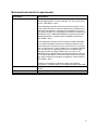
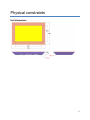
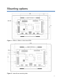
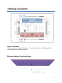
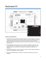
Samsung SUR40 for Microsoft ® Surface®
Enclosure Guide
LAST UPDATED: 02 DECEMBER 2011
1
Copyright notice
© Copyright 2011 Samsung Electronics Co., Ltd., 416, Maetan 3-Dong, Yeongtong-Gu, SuwonCity, Kyunggi-Do, the Republic of Korea.
All rights reserved. Copyright in this Guide is owned by Samsung Electronics Co., Ltd. (including
its affiliates, “Samsung”). You may copy this Guide only for the purpose of non-commercial use
within your organization, provided that any copy of this Guide or any portion hereof must include
this copyright notice.
Except as expressly provided above, nothing herein shall be construed as, conferring any right
or license under any copyrights, patents, trademarks or other intellectual property rights of
Samsung or any third party. Without limiting the generality of the foregoing, any product,
software, service or technology described or referenced in this document is the subject of
intellectual property rights reserved by Samsung or its licensors and is not licensed hereunder.
THIS DOCUMENTATION IS BEING PROVIDED “AS IS” AND WITHOUT WARRANTY OF ANY
KIND. THE ENTIRE RISK AS TO THE COMPLETENESS, RESULTS AND PERFORMANCE
OF THE INFORMATION IS ASSUMED BY THE RECIPIENT OF THIS DOCUMENTATION.
ALL WARRANTIES, WHETHER EXPRESS, IMPLIED, OR STATUTORY, INCLUDING THE
IMPLIED WARRANTIES OF MERCHANTABILITY, FITNESS FOR A PARTICULAR PURPOSE,
TITLE AND NONINFRINGEMENT, WITH RESPECT TO THE DOCUMENTATION ARE
DISCLAIMED.
2
Contents
4
Introduction
4
Scope
4
Specific criteria for enclosures
5
Mechanical and electrical requirements
6
Physical constraints
6
Unit dimensions
7
Mounting options
8
Venting locations
8
Angle orientation
8
Minimum distance to back plane
9
Dedicated I/O
9
Safety considerations
10
Sample scenario and mounting: Internal frame
16
Sample scenario and mounting: VESA mount
3
Introduction
The Samsung SUR40 for Microsoft® Surface® (“SUR40”) unit enables people to communicate,
collaborate and connect by easily interacting with digital content using touch and physical
objects. SUR40 is designed in a revolutionary horizontal table-like form that enables people to
interact with the display from any point around the device, and can also be mounted vertically or
on a tilt. The device can be customized by designing an external enclosure or kiosk that
cohesively integrates the unit into your environment and at the same time entices people to
interact with it. The custom enclosure should be designed allowing the device to be embedded
while maintaining complete access for service. If you choose to customize the exterior of the
unit with a custom enclosure, this document provides important guidelines to follow during the
design process.
Scope
This document is intended to provide guidelines that will allow you to create a customized
experience for your specific venue.
Specific criteria for enclosures
When you design a custom enclosure, you must consider a number of specific criteria. Note:
Embedding a SUR40 device into an “enclosure” must not cause the device to operate outside of
its’ designed specifications. Additionally, the enclosure must not obstruct an authorized service
technician from providing on-site service to that unit. Unless otherwise negotiated, doing so
may void the warranty or increase service costs.
Details of limitations include the following:
1. Do not modify the physical components of the unit. You should not modify device in any way
including, but not limited to, the external housing or top border, power cords, or any internal
components. The device is certified and compliant per international regulatory agencies.
Modification may void the certification and the warranty.
2. The unit must be accessible by a technician. Access to service the device has been
provided by an access panel attached to the back of the device. Please note one exception;
it is permissible to obstruct the device access panel only when attached to a VESA
approved mount. This would not require difficult disassembly.
3. No more than two people should be required to remove the unit from an enclosure. If more
than two people are needed, the enclosure must allow easy access or removal by
mechanical means, such as hydraulic cylinder jacks or removable panels.
4. The device serial number is located on the access panel. Please ensure it is accessible and
readable.
5. Please read the warranty; any custom enclosures that violate the warranty may void the
warranty.
4
Mechanical and electrical requirements
Requirement
Strength & stability
Specifications
Enclosure must not fall over when tilted to an angle of 10° from its
normal upright position. All doors, drawers, etc. are closed during
the test. (IEC 60950-1, 2001)
A floor-standing unit shall not fall over when a force equal to 20 %
of the weight of the unit, but not more than 250 N, is applied in any
direction except upwards, at a height not exceeding 2 m from the
floor. Doors, drawers, etc., which may be moved for servicing by the
OPERATOR or by a SERVICE PERSON, are placed in their most
unfavorable position, consistent with the installation instructions.
(IEC 60950-1, 2001)
A floor-standing unit shall not fall over when a constant downward
force of 800 N is applied at the point of maximum moment to any
horizontal surface of at least 12,5 cm by at least 20 cm, at a height
up to 1 m from the floor. Doors, drawers, etc., are closed during this
test. The 800 N force is applied by means of a suitable test tool
having a flat surface of approximately 12,5 cm by 20 cm. The
downward force is applied with the complete flat surface of the test
tool in contact with the EUT; the test tool need not be in full contact
with uneven surfaces (for example, corrugated or curved surfaces).
(IEC 60950-1, 2001)
AC power
Minimal heat load
Operating temperature
Enclosure must be able to withstand a static load of 2000 N
(equivalent to 1.5 Safety factor of unit weight plus 800 N static load).
100-240 VAC
15-20A
221 Watts/755 BTU/hour
5°C-30°C ambient
5
Physical constraints
Unit dimensions
103
6
Mounting options
Figure 1 – 600mm x 400mm x 8mm holes VESA
Figure 2 – Internal frame mounting holes
7
Venting locations
Angle orientation
Device can be mounted from 0-90 degrees. Zero, being horizontal and 90 being vertically
mounted such as on a VESA wall mount.
Minimum distance from back plane
8
Dedicated I/O
Safety considerations
1. Locate electrical power outlets and network connections in the floor adjacent to the unit. If
that location is not possible, route all external cables in a way that minimizes their potential
as tripping hazards. You can place a power outlet under the unit if it is elevated on a
platform and provides unfettered access to the outlet so that a technician can easily unplug
the power cord.
2. Do not impede access to the power cord, I/O connections, AC/Main rocker switch, and
On/Standby button. All of these items must be easily and quickly accessible so you can
easily turn the unit on and off and so a technician can easily service these items, if
necessary.
3. Consider external vibration, air flow, temperature, power, and other operating conditions to
make sure the SUR40 unit functions properly.
4. Use appropriate safety-rated (for example, UL certification) materials for your custom
enclosure.
9
Sample scenario and mounting:
Internal frame
This scenario involves mounting a SUR40 into a table. In this instance, the unit is mounted to
the internal frame (see Figure 2) to a hanger plate that has two adjustments.
10
11
12
13
14
15
Sample scenario and mounting:
VESA mount
16
17