1
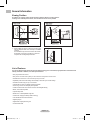
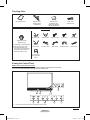
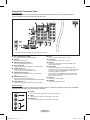
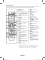
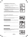
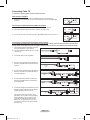
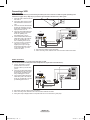
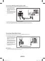
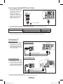
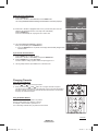
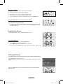
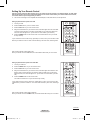
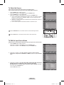
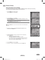
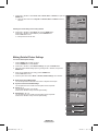
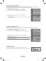
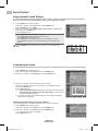
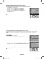
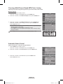
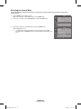
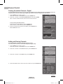
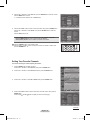
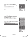
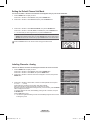
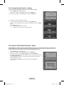
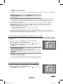
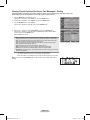
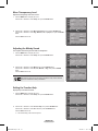
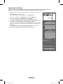
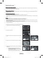
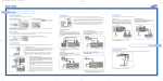
DLP TV Owner’s Instructions HL-T5055W HL-T5655W Register your product at www.samsung.com/global/register Record your Model and Serial number here for future reference. ▪ Model _______________ ▪ Serial No. _______________ BP68-00626D-00Eng-1.indd 1 2007-04-13 ソタネト 1:13:36 A Guide to Digital TV • What is Digital Television? Digital television (DTV) is a new way of transmitting high quality video and audio to your TV set. Using DTV, broadcasters can transmit high definition TV (HDTV) images, Dolby digital surround audio, and new services such as multicasting (transmitting more than one program on the same TV channel) and datacasting. Several of these services can be combined into a single digital broadcast. Digital Television Services • Digital Picture Quality DTV programs are transmitted in two different formats. The first is Standard Definition Television (SDTV) and the second is High Definition Television (HDTV). • SDTV program formats include 480-line interlaced (480i) and 480-line progressive (480p) video. 480i programs are essentially a digital version of our current analog TV programs, while the 480p format offers improved image detail over 480i. Some 480p programs are broadcast in widescreen and are comparable to progressive-scan DVD movies in image quality. • HDTV program formats include 1080-line interlaced (1080i) and 720-line progressive (720p). Both HDTV formats are always broadcast in widescreen, and offer much higher picture quality than SDTV. • Dolby Surround Sound With DTV, you can listen to a variety of Dolby digital audio formats from Dolby Surround 2.0 to Dolby Digital 5.1 surround, using your home audio system. Many HDTV programs are now broadcast with DD 5.1 soundtracks. © 2007 Samsung Electronics Co., Ltd. All rights reserved. English - 2 BP68-00626D-00Eng-1.indd 2 2007-04-13 ソタネト 1:13:36 Q&A 1. Is the antenna I use for existing TV reception good enough for DTV? Over-the-air (OTA) digital TV broadcasting uses the same channels as analog TV and works well with many existing TV antennas. However, DTV broadcast channel assignments are different than analog channels. You should find out whether your local DTV broadcasts are on VHF (channels 2-13) or UHF (channels 14-69) to see if you need a different antenna. If your DTV channels are on UHF and you already get good UHF reception, your present antenna may work fine. The same holds true for VHF DTV reception. Note that in some markets, both VHF and UHF channels are used for DTV broadcasts. You can find out the latest DTV channel assignments for your area by browsing selected Internet web sites such as www.titantv.com, www.10000watts.com, and www.fcc.gov. 2. How difficult is it to receive DTV signals indoors? This depends on whether your local DTV stations are running full power or not and how close your location is to the transmission tower. DTV receivers do not require as much signal as analog TV receivers to produce high-quality images and sound. Once the DTV signal level exceeds a certain threshold at the receiver, the digital video and audio data is decoded at the same quality it was originally encoded for broadcast. This is a big advantage for DTV over analog TV - there is no noise, ghosting, static, or scratchy audio. 3. How can I connect an antenna in my townhouse, co-operative apartment, condominium, or apartment? The Federal Communications Commission’s OTARD Rule (part of the Telecommunications Act of 1996) allows residents of condominiums, townhouse, or members of neighborhood associations to put up outside antennas for reception of broadcast TV signals as long as those antennas are not located in common areas and are no more than 12’ in height. Residents of rental units (apartments, etc.) are not covered by the OTARD rules and will have to use indoor antennas to receive DTV broadcasts. It is possible that the landlord of an apartment complex can provide broadcast DTV signals via a master TV antenna system to each apartment. 4. Can I connect my DTV set-top receiver to my cable TV service? Cable TV systems use a different method for transmitting digital TV programs that is currently incompatible with broadcast DTV set-top receivers. So you will still need to use an outdoor or indoor antenna to receive OTA broadcast DTV programs. The good news is that you won’t have to pay a monthly or per-program charge to watch OTA DTV and HDTV programs. They’re free, unlike subscription satellite TV or premium cable TV. All you need is an antenna and a DTV set-top receiver to enjoy clear, sharp widescreen images and high-quality audio. English - 3 BP68-00626D-00Eng-1.indd 3 2007-04-13 ソタネト 1:13:36 Contents CHANNEL CONTROL GENERAL INFORMATION ■ ■ ■ ■ ■ ■ ■ Viewing Position.........................................................5 List of Features ..........................................................5 Checking Parts ...........................................................6 Viewing the Control Panel .......................................... 6 Viewing the Connection Panel ......................................8 Remote Control .............................................................9 Installing Batteries in the Remote Control ..................10 CONNECTIONS ■ ■ ■ ■ ■ ■ ■ ■ ■ ■ Connecting VHF and UHF Antennas ..........................10 Connecting Cable TV ..................................................11 Connecting a VCR ......................................................12 Connecting a Camcorder ............................................13 Connecting a DVD Player/Set-Top Box ......................13 Connecting a DVD Player/Set-Top Box via HDMI ......13 Connecting a DVD Player/Set-Top Box via DVI..........14 Connecting a Digital Audio System.............................14 Connecting an Amplifier/DVD Home Theater .............15 Connecting a PC .........................................................15 OPERATION ■ ■ ■ ■ ■ ■ ■ ■ ■ ■ Turning the TV On and Off ..........................................16 Plug & Play Feature ....................................................16 Changing Channels ....................................................17 Adjusting the Volume ..................................................18 Viewing the Display ....................................................18 Viewing the Menus .....................................................19 Memorizing the Channels ...........................................19 Setting Up Your Remote Control .................................21 To Select the Source ...................................................26 To Edit the Input Source Name ...................................26 PICTURE CONTROL ■ ■ ■ ■ ■ ■ ■ ■ ■ ■ Using Automatic Picture Settings................................27 Making Detailed Picture Settings ..........................28 Changing the Screen Size ..........................................29 Digital Noise Reduction ..............................................30 DNIe (Digital Natural Image engine) ...........................30 Setting the Color Gamut .........................................31 Selecting the Film Mode .............................................31 Setting the Blue Screen Mode ....................................32 Setting the HDMI Black Level ................................32 Freezing the Picture ....................................................32 ■ ■ ■ ■ ■ ■ ■ ■ ■ Clearing Scrambled Channels - Digital .......................37 Adding and Erasing Channels ....................................37 Setting Your Favorite Channels ..................................38 Viewing the Channel Lists ..........................................39 Setting the Default Channel List Mode .......................40 Labeling Channels - Analog ........................................40 Fine Tuning Analog Channels - Analog.......................41 Checking the Digital-Signal Strength - Digital .............41 LNA (Low Noise Amplifier) ..........................................42 PC DISPLAY ■ ■ ■ ■ ■ Using Your TV as a Computer (PC) Display ...............42 Display Modes ............................................................42 Setting up the TV with your PC ...................................43 Changing the Picture Size (PC Mode) .................45 Setting the Home Theater PC ...............................45 FUNCTION DESCRIPTION ■ ■ ■ ■ ■ ■ ■ ■ ■ ■ Selecting a Menu Language .......................................46 Setting the Time ..........................................................46 Using the Game Mode ................................................48 Using the V-Chip .........................................................49 Viewing Closed Captions (On-Screen Text Messages) - Analog .........................52 Viewing Closed Captions (On-Screen Text Messages) - Digital ..........................53 Menu Transparency Level ..........................................54 Adjusting the Melody Sound ..................................54 Setting the Function Help ...........................................54 Upgrading the Software ..........................................55 APPENDIX ■ ■ ■ ■ ■ Troubleshooting ..........................................................56 Replacing the Lamp ....................................................57 Cleaning and Maintaining Your TV .............................58 Using Your TV in Another Country ..............................58 Specifications ..............................................................59 SOUND CONTROL ■ ■ ■ ■ ■ ■ ■ Using Automatic Sound Settings ................................33 Customizing the Sound ...............................................33 Setting up DNSe (Digital Natural Sound engine) ........34 Choosing a Multi-Channel Sound (MTS) Track - Digital .......34 Choosing a Multi-Channel Sound (MTS) Track - Analog ......35 Automatic Volume Control ..........................................35 Selecting the Internal Mute .........................................36 Symbols Press ☛ ➢ Important Note One-Touch Button English - 4 BP68-00626D-00Eng-1.indd 4 2007-04-13 ソタネト 1:13:37 General Information Viewing Position To optimize your viewing comfort, please follow the guidelines below for viewing distance. If viewing for an extended period of time, sit as far back from the screen as possible. ➢ When installing the product, make sure to keep it away from the wall (more than 10cm / 4inches) for ventilation purposes. Poor ventilation may cause an increase in the internal temperature of the product, resulting in a shortened component life and degraded performance. List of Features Your TV was designed and engineered using the latest technology. It is a full-featured, high-performance unit that exceeds industry standards. In addition, it has these special features: • Easy-to-operate remote control • Easy-to-use on-screen menu system you can access from front panel or remote control • Automatic timer to turn the TV on and off at any time you choose • Adjustable picture and sound settings and the ability to memorize your favorite settings • Automatic channel tuning for up to 181 channels • A special filter to reduce or eliminate reception problems • Fine tuning control for the sharpest picture possible • A built-in multi-channel sound decoder for stereo and bilingual listening • Built-in, dual channel speakers • A special sleep timer • Widescreen TV with adjustable image size • Life-like clear images provided by DNle technology • Color Weakness Enhancement Feature • Digital Input jack • Digital Audio Output (OPTICAL) jack • Theater Game Mode English - 5 BP68-00626D-00Eng-1.indd 5 2007-04-13 ソタネト 1:13:37 Checking Parts Owner’s Instructions Remote Control (BP59-00123A)/ AAA Batteries Warranty Card/ Registration Card/ Safety Guide Manual/ Quick Guide Manual Power Cord (3903-000144) Sold Separately S-Video Cable Antenna Cable Component Cables Audio Cables Video Cables D-Sub Cable PC Audio Cable HDMI Cable HDMI/DVI Cable Optical Cable Replacement Lamp (BP96-01472A) For purchasing a replacement lamp, ask at a nearby service center. • Use authorized lamps only. The company cannot guarantee the quality of the product if an unauthorized lamp is used. 3.5 mm Stereo mini-plug/2RCA Cable Viewing the Control Panel Buttons on the Lower Part of the Panel The buttons on the lower panel control your TV’s basic features, including the on-screen menu. To use the more advanced features, you must use the remote control. ➢ The product color and shape may vary depending on the model. Continued... English - 6 BP68-00626D-00Eng-1.indd 6 2007-04-13 ソタネト 1:13:43 1 POWER Press to turn the TV on and off. 2 Remote Control Sensor Aim the remote control towards this spot on the TV. 3 Indicator Lights Blinks and turns off when the power is on and lights up in stand-by mode. 4 SOURCE Toggles between all the available input sources (TV, AV1, AV2, AV3, S-Video1, S-Video2, S-Video3 Component1, Component2, PC, HDMI1/DVI, or HDMI2). 6 + VOL – Press to increase or decrease the volume. In the on-screen menu, use the + VOL – buttons as you would use the ◄ and ► buttons on the remote control. 7 CH Press to change channels. In the on-screen menu, use the CH buttons as you would use the ▲ and ▼ buttons on the remote control. 8 (ENTER) Press to confirm a selection. 5 MENU Press to see an on-screen menu of your TV’s features. Indicator Light Key ( : On, : Blinking, STAND BY/TEMP : Off) TIMER LAMP Indication Standby state. The picture will automatically appear in about 15 seconds. Auto Timer ON/OFF has been set and the set will automatically be turned on in about 15 seconds. A cooling fan inside the set is not operating normally. Lamp cover on the rear of the set is not properly shut. Check if the ventilation hole on the rear of the set is blocked, because if the inner temperature is too high, the power will shut off. Lamp may be defective. Please contact a certified technician. ➢ It takes about 30 seconds for the TV to warm up, so normal brightness may not appear immediately. The TV has a fan to keep the inside lamp from overheating. You’ll occasionally hear it working. You can use the channel selection buttons to switch on the TV when it is in standby mode depending on the model. When using the on-screen menu the volume adjustment and channel selection buttons have the same function as the ▲/▼/◄/► buttons on the remote control. ◆ If the remote control no longer works or you have lost it, you can use controls on the panel of the TV. ◆ ◆ ◆ ◆ English - 7 BP68-00626D-00Eng-1.indd 7 2007-04-13 ソタネト 1:13:49 Viewing the Connection Panel Rear Panel Jacks Use the rear panel jacks to connect A/V components that will be connected continuously, such as VCR or DVD players. For more information on connecting equipment, see pages 12-15. ➢ The product color and shape may vary depending on the model. 1 ANT 1 IN(CABLE)/ANT 2 IN(AIR) 75Ω Coaxial connector for Air/Cable Network. 2 SERVICE This jack is for service only. 3 DIGITAL AUDIO OUT (OPTICAL) Connect to a Digital Audio component. 4 DVI IN (AUDIO-L/R) Connect to the DVI audio output jack of an external device. 5 S-VIDEO (AV IN 1, 2) Video input for external devices with an S-Video output, such as a Camcorder or VCR. 6 VIDEO/AUDIO-L/R (AV IN 1, 2) Video input for external devices, such as a Camcorder or VCR. 7 VIDEO/AUDIO OUT (L/R) Video/Audio outputs for external devices. Video output is not avaiable RF(Digital)/Component/PC/HDMI. 8 COMPONENT IN 1, 2 Video (Y/PB/PR) and audio (L-AUDIO-R) Component inputs. 9 PC IN Connect to the video output jack on your PC. 0 PC AUDIO IN Connect to the audio output jack on your PC. ! HDMI IN 2 Connect to the HDMI jack of a device with HDMI output. (Not compatible with PC) @ HDMI 1/DVI IN Connect to the HDMI jack of a device with HDMI output. This input can also be used as a DVI connection with separate analog audio inputs. An optional HDMI/DVI cable will be necessary to make this connection. When using an optional HDMI/DVI adapter, the DVI analog audio inputs on your TV allow you to receive left and right audio from your DVI device. # SERVICE 2 This jack is for software upgrade. $ POWER IN Connect the supplied power cord. Side Panel Jacks Use the right side panel jacks to connect a component that is used only occasionally (a camcorder or video game, for example). The product color and shape may vary depending on the model. 1 S-VIDEO Connect an S-Video signal from an S-VHS VCR or DVD player. 2 VIDEO Connect the video signal from a camcorder or video game. 3 AUDIO (L/R) Connect the audio signal from a camcorder or video game. English - 8 BP68-00626D-00Eng-1.indd 8 2007-04-13 ソタネト 1:13:50 Remote Control You can use the remote control up to a distance of about 23 feet from the TV. When using the remote, always point it directly at the TV. You can also use your remote control to operate your VCR, Cable box, DVD Player, or Set-Top Box. 1 POWER Turns the TV on and off. 2 Numeric Buttons Press to directly select a channel. 3 – Press to select additional channels being broadcast by the same station. For example, to select channel “54-3”, press “54”, then press “–” and “3”. 4 CH LIST Used to display Channel Lists on the screen. 5 ANTENNA Press to select “Air” or “Cable”. 6 VOL +, VOL – Press to increase or decrease the volume. 7 MUTE Press to temporarily cut off the sound. 8 MENU Displays the main on-screen menu. 9 RETURN Returns to the previous menu. 0 S.MODE Press to select the sound mode. ! P.MODE Press to select the picture mode. @ SLEEP Press to select a preset time interval for automatic shut off. # GAME Press to select various Game settings. $ MTS Press to choose Stereo, Mono or Separate Audio Program (SAP broadcast). % SET Sets the remote to control your TV, VCR, Cable, DVD, or Set-Top Box. ^ TV, DVD, STB, CABLE, VCR Press to operate your TV, DVD, STB, CABLE (box), or VCR. & SOURCE Press to display all of the available video sources. * Press to backlight the VOL, CH, and the active source button (TV, DVD, CABLE, STB, VCR) on the remote control. ( PRE-CH Tunes to the previous channel. ) FAV.CH Press to switch to your favorite channels. a HDMI Selects the HDMI mode directly. b VCR/DVD Functions - Rewind - Stop - Play/Pause - Fast Forward c CH , CH Press to change channels. d EXIT Press to exit from the menu. e UP▲/DOWN▼/LEFT◄/RIGHT►/ ENTER Use to select on-screen menu items and change menu values. f INFO Press to display information on the TV screen. g CAPTION Controls the caption decoder. h STILL Press to stop the action during a particular scene. Press again to resume normal video. i Color buttons Press to add or delete channels and to store channels to the favorite channel list in the “Channel List” menu. (Refer to pages 37~39) j P.SIZE Press to change the screen size. k ADD/DEL Use to store and delete channels to/ from memory. l DNSe DNSe enhances the sound quality, automatically controls output, and prevents sound distortion. Press this button to set it On or Off. (Refer to page 34) m RESET When your remote control does not work, change the batteries and press the RESET button for 2-3 seconds before use. ➢ This is a special remote control for the visually impaired person, and has Braille points on the POWER, Channel, Volume, STOP, and PLAY/PAUSE buttons. ➢ The performance of the remote control may be affected by bright light. English - 9 BP68-00626D-00Eng-1.indd 9 2007-04-13 ソタネト 1:13:55 Installing Batteries in the Remote Control 1 Lift the cover at the back of the remote control upward as shown in the figure. 2 Install two AAA size batteries. ➢ Make sure to match the “+” and “–” ends of the batteries with the diagram inside the compartment. ➢ Do not mix battery types, i.e. alkaline and manganese. 3 Close the cover as shown in the figure. ➢ Remove the batteries and store them in a cool and dry place if you won’t be using the remote control for a long time. The remote control can be used up to about 23 feet from the TV. (Assuming typical TV usage, the batteries last for about one year.) ➢ If the remote control doesn’t work, check the following 1. Is the TV power on? 2. Are the plus and minus ends of the batteries reversed? 3. Are the batteries drained? 4. Is there a power cut, or is the power cord unplugged? 5. Is there a special fluorescent light or a neon sign nearby? Connecting VHF and UHF Antennas If your antenna has a set of leads that look like this, see “Antennas with 300 Ω Flat Twin Leads” below. If your antenna has one lead that looks like this, see “Antennas with 75 Ω Round Leads”. If you have two antennas, see “Separate VHF and UHF Antennas”. Antennas with 300 Ω Flat Twin Leads If you are using an off-air antenna (such as a roof antenna or “rabbit ears”) that has 300 Ω twin flat leads, follow the directions below. 1 Place the wires from the twin leads under the screws on a 300-75 Ω adapter (not supplied). Use a screwdriver to tighten the screws. 2 Plug the adaptor into the ANT 1 IN(CABLE) or ANT 2 IN(AIR) terminal on the rear of the TV. Antennas with 75 Ω Round Leads 1 Plug the antenna lead into the ANT 1 IN(CABLE) or ANT 2 IN(AIR) terminal on the rear of the TV. Separate VHF and UHF Antennas If you have two separate antennas for your TV (one VHF and one UHF), you must combine the two antenna signals before connecting the antennas to the TV. This procedure requires an optional combiner-adaptor (available at most electronics shops). 1 Connect both antenna leads to the combiner. 2 Plug the combiner into the ANT 1 IN(CABLE) or ANT 2 IN(AIR) terminal on the bottom of the rear panel. English - 10 BP68-00626D-00Eng-1.indd 10 2007-04-13 ソタネト 1:13:59 Connecting Cable TV To connect to a cable TV system, follow the instructions below. Cable without a Cable Box 1 ➢ Plug the incoming cable into the ANT 1 IN(CABLE) terminal on the rear of the TV. Because this TV is cable-ready, you do not need a cable box to view unscrambled cable channels. Connecting to a Cable Box that Descrambles All Channels 1 ➢ Find the cable that is connected to the ANT OUT terminal on your cable box. This terminal might be labeled “ANT OUT”, “VHF OUT” or simply, “OUT”. 2 Connect the other end of this cable to the ANT 1 IN(CABLE) terminal on the rear of the TV. ANT IN ANT OUT Connecting to a Cable Box that Descrambles Some Channels If your cable box descrambles only some channels(such as premium channels), follow the instructions below. You will need a two-way splitter, an RF (A/B) switch, and four lengths of Antenna cable. (These items are available at most electronics stores.) 1 ➢ 2 Find and disconnect the cable that is connected to the ANT IN terminal on your cable box. This terminal might be labeled “ANT IN”, “VHF IN” or simply, “IN”. ANT IN Connect this cable to a two-way splitter. Incoming cable 3 Connect an Antenna cable between an OUTPUT terminal on the splitter and the IN terminal on the cable box. Incoming cable Splitter Splitter Cable Box 4 Connect an Antenna cable between the ANT OUT terminal on the cable box and the B-IN terminal on the RF (A/B) switch. Incoming cable Splitter RF (A/B) Switch Cable Box 5 Connect another cable between the other OUT terminal on the splitter and the A-IN terminal on the RF (A/B) switch. Incoming cable Splitter Cable Box 6 RF (A/B) Switch Connect the last Antenna cable between the OUT terminal on the RF (A/B) switch and the ANT IN 1 (CABLE) terminal on the rear of the TV. Incoming cable After you have made this connection, set the A/B switch to the “A” position for normal viewing. Set the A/B switch to the “B” position to view scrambled channels. (When you set the A/B switch to “B”, you will need to tune your TV to the cable box’s output channel, which is usually channel 3 or 4.) Splitter Cable Box RF (A/B) Switch TV Rear Panel English - 11 BP68-00626D-00Eng-1.indd 11 2007-04-13 ソタネト 1:14:03 Connecting a VCR Video Connection These instructions assume that you have already connected your TV to an antenna or a cable TV system (according to the instructions on pages 10~11). Skip step 1 if you have not yet connected to an antenna or a cable system. 1 2 3 4 5 ➢ Unplug the cable or antenna from the rear of the TV Connect the cable or antenna to the ANT IN terminal on the back of the VCR. Connect an Antenna Cable between the ANT OUT terminal on the VCR and the ANT 1 IN(CABLE) or ANT 2 IN(AIR) terminal on the TV. Connect a Video Cable between the VIDEO OUT jack on the VCR and the AV IN 1 [VIDEO] (or AV IN 2 [VIDEO]) jack on the TV. Connect Audio Cables between the AUDIO OUT jacks on the VCR and the AV IN 1 [L-AUDIO-R] (or AV IN 2 L-AUDIO-R) jacks on the TV. If you have a “mono” (non-stereo) VCR, use a Y-connector (not supplied) to hook up to the right and left audio input jacks of the TV. If your VCR is stereo, you must connect two cables. TV Rear Panel VCR 5 Audio Cable(Not supplied) 2 4 Video Cable(Not supplied) 3 Antenna cable(Not supplied) ➢ ➢ Each VCR has a different panel configuration. When connecting a VCR, match the color of the connection terminal to the cable. S-Video Connection Your Samsung TV can be connected to the S-Video jack of a VCR. (This connection delivers a better picture when compared to the regular Video connection above.) 1 2 3 To begin, follow steps 1–3 in the previous section to connect the antenna or cable to your VCR and your TV. Connect an S-Video Cable between the S-VIDEO OUT jack on the VCR and the AV IN 1 [S-VIDEO] (or AV IN 2 [S-VIDEO]) jack on the TV. Connect Audio Cables between the AUDIO OUT jacks on the VCR and the AV IN 1 [L-AUDIO-R] (or AV IN 2 [L-AUDIO-R]) jacks on the TV. TV Rear Panel VCR 5 Audio Cable (Not supplied) 4 S-Video Cable(Not supplied) 3 Antenna cable(Not supplied) ➢ ➢ ➢ Each S-VHS VCR has a different panel configuration. When connecting a VCR, match the color of the connection terminal to the cable. Some games may be displayed with a cut off picture when the TV is connected to a game player. English - 12 BP68-00626D-00Eng-1.indd 12 2007-04-13 ソタネト 1:14:07 Connecting a Camcorder The side panel jacks on your TV make it easy to connect a camcorder to your TV. They allow you to view the camcorder tapes without using a VCR. 1 2 Connect a Video Cable or S-Video Cable between the AV IN 3 [VIDEO] or [S-Video] jack on the TV and the VIDEO OUT jack on the camcorder. Connect Audio Cables between the AV IN 3 [L-AUDIO-R] jacks on the TV and the AUDIO OUT jacks on the camcorder. TV Side Panel 1 S-Video Cable(Not supplied) or Camcorder 1 Video Cable(Not supplied) 2 Audio Cable(Not supplied) ➢ ➢ Each Camcorder has a different panel configuration. When connecting a Camcorder, match the color of the connection terminal to the cable. Connecting a DVD Player/Set-Top Box The rear panel jacks on your TV make it easy to connect a DVD Player/Set-Top Box. 1 2 Connect Component Cables between the COMPONENT IN 1 [Y, PB, PR] (or COMPONENT IN 2 [Y, PB, PR]) jacks on the TV and the COMPONENT OUT [Y, PB, PR] jacks on the DVD Player/Set-Top Box. Connect Audio Cables between the COMPONENT IN 1 [L-AUDIO-R] (or COMPONENT IN 2 [L-AUDIO-R]) jacks on the TV and the AUDIO OUT jacks on the DVD Player/ Set-Top Box. TV Rear Panel DVD Player/Set-Top Box 2 Audio Cable(Not supplied) 1 Component Cable(Not supplied) ➢ ➢ ➢ Component video separates the video into Y (Luminance (brightness)), PB (Blue) and PR (Red) for enhanced video quality. Be sure to match the component video and audio connections. For example, if connecting the video cable to COMPONENT IN 1, connect the audio cable to COMPONENT IN 1 also. Each DVD Player/Set-Top box has a different panel configuration. When connecting a DVD Player/Set-Top box, match the color of the connection terminal to the cable. Connecting a DVD Player/Set-Top Box via HDMI This connection can only be made if there is an HDMI Output jack on the external device. This connection will provide the highest quality picture. 1. Connect an HDMI Cable between the HDMI IN 2 on the TV and the HDMI OUT on the DVD Player/ Set-Top Box. DVD Player / Set-Top Box 1 TV Rear Panel HDMI Cable (Not supplied) What is HDMI? ● HDMI, or high-definition multimedia interface, is an interface that enables the transmission of digital audio and video signals using a single cable. ● “Multimedia interface” is a more accurate name for it especially because it allows multiple channels of digital audio (5.1 channels). The difference between HDMI and DVI is that the HDMI device is smaller in size, has the HDCP (High Bandwidth Digital Copy Protection) coding feature installed, and supports multi-channel digital audio. ➢ Each DVD Player/Set-Top box has a different panel configuration. ➢ When connecting a DVD Player/Set-Top box, match the color of the connection terminal to the cable. ➢ When connecting via HDMI, you do not need to connect Audio Cables. You only need to connect Audio cables when connecting via HDMI/DVI. English - 13 BP68-00626D-00Eng-1.indd 13 2007-04-13 ソタネト 1:14:14 Connecting a DVD Player/Set-Top Box via DVI This connection can only be made if there is a DVI Output jack on the external device. 1 2 Connect a HDMI/DVI Cable or DVI-HDMI Adapter between the HDMI 1/DVI IN jack on the TV and the DVI jack on the DVD Player/ Set-Top Box. Connect Audio Cables between the DVI IN [L-AUDIO-R] jack on the TV and the AUDIO OUT jacks on the DVD Player/Set-Top Box. TV Rear Panel DVD Player/Set-Top Box 2 Audio Cable(Not supplied) 1 HDMI/DVI Cable(Not supplied) ➢ ➢ ➢ Each DVD Player/Set-Top box has a different panel configuration. When connecting a DVD Player/Set-Top box, match the color of the connection terminal to the cable. When using an HDMI/DVI cable connection, you must connect to the HDMI 1/DVI IN terminal on the TV. Connecting a Digital Audio System The rear panel jacks on your TV make it easy to connect a Digital Audio System to your TV. ➢ Each Digital Audio System has a different panel configuration. 1 ➢ Connect an Optical Cable between the DIGITAL AUDIO OUT (OPTICAL) jack on the TV and the Digital Audio Input jack on the Digital Audio System. When a Digital Audio System is connected to the DIGITAL AUDIO OUT (OPTICAL) terminal: Decrease the gain (volume) of the TV, and adjust the volume level with the system’s volume control. 5.1CH audio is possible when the TV is connected to an external device supporting 5.1CH. TV Rear Panel Digital Audio System 1 Optical Cable (Not supplied) What is OPTICAL? Converts the electric signal into an optical light signal, and transmits it through glass fibers. S/PDIF is a transmission system of digital audio in the form of a light wave that uses a glass conductor. English - 14 BP68-00626D-00Eng-1.indd 14 2007-04-13 ソタネト 1:14:21 Connecting an Amplifier/DVD Home Theater 1 Connect Audio Cables between the AUDIO OUT [L-AUDIO-R] on the TV and AUDIO IN [L-AUDIO-R] on the Amplifier/DVD Home Theater. When an audio amplifier is connected to the “AUDIO OUT [L-AUDIO-R ]” terminals: Decrease the gain (volume) of the TV, and adjust the volume level with the Amplifier’s volume control. TV Rear Panel Amplifier/ DVD Home Theater 1 ➢ ➢ Audio Cable (Not supplied) Each Amplifier/DVD Home Theater has a different panel configuration. When connecting an Amplifier/DVD Home Theater, match the color of the connection terminal to the cable. AV OUT L-AUDIO-R DIGITAL AUDIO OUT (OPTICAL) RF (Digital/Analog), AV, S-Video, Component, HDMI Sound is output Sound is output RF (Digital/Analog), AV, S-Video, Component HDMI Sound is not output If you want to play movies by connecting DVD Player or Set-Top Box to the COMPONENT IN jacks on the TV, ➢ connect the Optical OUT jack on the DVD Player or Set-Top Box to an Amplifier or DVD Home Theater. Connecting a PC Using the D-Sub Cable 1 2 Connect a D-Sub Cable between the PC IN [PC] jack on the TV and the PC output jack on your computer. Connect a PC Audio Cable between the PC IN [AUDIO] jack on the TV and the Audio Out jack of the sound card on your compute