1
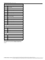
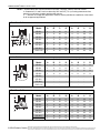
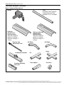
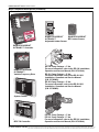
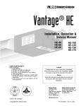
Custom-Engineered, Low-Intensity Infrared Heating Systems Submittal: CRV-Series Job: Location: Engineer: Gas Specs: Date: QTY. MODEL NO. CRV UNIT INPUT BTU/HR QTY. MODEL NO. CRV UNIT INPUT BTU/HR QTY. MODEL NO. CRV UNIT INPUT BTU/HR QTY. MODEL NO. CRV UNIT INPUT BTU/HR TOTAL INPUT BTU/HR Important Before installation and operation of heating equipment, read and understand the Installation, Operation and Service Manual. Applications, engineering and detailed guidance on systems design, installation and product performance is available upon request. ROBERTS GORDON® products are to be installed only in accordance with local laws, codes and regulations, and only by a contractor qualified in the installation and service of gas-fired heating equipment. Roberts-Gordon Roberts-Gordon 1250 William Street P.O. Box 44 Buffalo, New York 14240-0044 Telephone: 716.852.4400 Fax: 716.852.0854 Toll Free: 800.828.7450 76 Main Street West Unit 10 Grimsby, Ontario L3M 1R6 Canada Telephone: 905.945.5403 Fax: 905.945.0511 www.rg-inc.com © Copyright 2004 Roberts-Gordon P/N127602NA Rev B 07/04 ROBERTS GOR DON® CRV-SE RI ES S UBMI TT AL S HE ET STANDARD PARTS LIST Contents of CRV-Series Burner Carton Part No. Description 0133580D 4" Coated 90° Elbow 01336101 Quantity 0270XXXX CRV-Series Burner (Rate and Fuel Varies) 1 91412200 1/2" Flex Gas Line 1 013676XX End Vent Plate 1 01397300 Accessory Package - 01361200 Filter Support Disk 1 01367800 Combustion Chamber Gasket 1 02724901 Door Assembly w/ Hole 1 91115100 Screw #10 - 24x5/8 4 91119500 U-Clip 4 91905500 Filter Support 1 92123900 Nut 5/16 - 18 2 92511601 Wing Nut #10 - 24 1 96411600 Lock washer 5/16" 2 01312401 Filter and Gasket 1 Common CRV-Series Components Part No. Description Combustion Chamber: 4" Aluminized 45° Elbow 0133610D 4" Coated 45° Elbow 91409300 16 Ga. Hot Rolled Steel 4" dia. 10' Tube 91409403 16 Ga. Non-heat treated Aluminized 4" dia. 10' Tube 91409408 16 Ga. Heat Treated Aluminized 4" dia. 10' Tube 91409420 16 Ga.Non-Heat Treated Aluminized 6" dia. 10' Tube 9141030D 16 Ga. Coated 4" dia. 10' Tube E0009105 16 Ga. Heat Treated Aluminized 6" dia. 10' Tube 91418200 Aluminized Tube Adapter 6" dia. x 4" dia. 02722100 4" Cast Iron Adapter 91240010 6" Tube Hanger Venting Accessories 01316000 Outside Air Supply Blower Mounting Kit 01324401 4" Outside Air Supply Takeoff 01326801 Outside Air Filter Housing 90707501 Air Supply Blower/Power Venter 91409601 4" Outside Air Flex Duct (Box of 8 - 8' sections) 90434501 Outside Air Pressure Switch 02722300-1P Hot Rolled Steel Combustion Chamber 02722301-1P Heat-Treated Aluminized Steel Combustion Chamber 0272230D-1P Porcelain Coated Steel Combustion Chamber 02721200-1P Cast Iron Combustion Chamber Tubing and Related Accessories 01312700 4" Plain Coupling Reflectors and Related Accessories 01329910 Reflector Side Extension Support 03050010 Reflector Support Package (Tubing) 02712700 Reflector Side Extension, 2 Clips, 2 Screws 02716400 Reflector Support Package (Schedule 40 Pipe) 02750303 Aluminum Reflector 027503SS Stainless Steel Reflector 01312706 6" Plain Coupling 02750304 0131270I 4" Lined Coupling Aluminum Reflector with Hole 027503SH Stainless Steel Reflector with Hole 01331900 4" Damper Coupling 02750800 E0009356 6" Damper Coupling Aluminum Reflector End Cap 027508SS Stainless Steel Reflector End Cap 0133022D 4" Coated Tee 027508SH Stainless Steel Reflector End Cap with Hole 01330203 4" Aluminized Tee 02750900 01330204 6" Aluminized Tee Reflector Joint 027509SS Stainless Steel Reflector Joint 0133092D 4" Coated Cross 027127SS Reflector Side Extension, Stainless Steel 01330903 4" Aluminized Cross 01330904 6" Aluminized Cross 01330800 4” Tube Plug 01335801 4" Aluminized 90° Elbow T0100320 6" Aluminized 90° Elbow 03090100 Tube and Reflector Hanger 02790300 Tube and Reflector Hanger, Cast Iron 91907302 “S” Hook 91903201 Turnbuckle 91903300 Spring Hook IN STALLATI ON AND OPER ATI ON OF HEATI NG EQUIPMENT, READ AND U NDERSTAND THE INSTALLATION, OPERATIO N AND SERVICE MANUAL. © 2004 Roberts-Gordon BEFORE APPLICATION S, ENGI NEERING AND DETAI LED GUID ANCE ON SYSTEMS DESIGN, INSTALLATI ON AND PRODUCT PERFORMANCE IS AVAI LABLE UPON REQUEST. ROBERTS GORDON PRODUCTS ARE TO BE ® INSTALLED ONLY IN ACCORDANCE WI TH LOCAL LAWS, CODES AND REGULATIONS, AND ONLY BY A CONTRACTOR QUALI FIED I N THE I NSTALLATION AND SERVICE OF GAS-FIRED HEATING EQUI PMENT. ROBERTS GORDON ® CRV-SE RI ES S UBM ITT AL S HE ET 91903202 Turnbuckle with Eyebolt Thermostats 02712100 Universal Shield Support 05023000 Load Relay Package 02751800 Universal Shield with Holes 90417600 Transformer Relay - SPST (12A) 02751801 Universal Shield 90436300 Transformer Relay - DPDT (12A) 027518SS Universal Shield, Stainless Steel 90423000 24V Low Voltage Thermostat (Marked 1-5) 90424300 Thermostat Guard Control Packages and Accessories BZC700 ROBERTS GORDON® BZC 700 Controller Deco Grille(1' x 8') 01363003 Bracket 01365901 End Piece 10001501 Water Resistant Sensor 01326801 Reinforcement 02770002 System Control 01365903 Joint Piece URVCCM 91406700 1' x 8' Protective Grille 10001500 Indoor Sensor*, ROBERTS GORDON BZC 700 Controller ® * One required per zone URVSC ROBERTS GORDON ® ULTRAVAC™Central Controller (with Modem Chip & Software) Includes: ROBERTS GORDON® ULTRAVAC™Controller Deco Grille(2' x 4') 10080142 Modem Chip 01365900 Shield Frame 10081501 Outdoor Sensor 01370408 Reflector Side Extension 8" x 48" 10080410 PC Connection Cable Package 01370412 Reflector Side Extension 12" x 48" 01370416 Reflector Side Extension 16" x 48" 91407000 Aluminum Grille 2' x 4' URVCCR URVSC ROBERTS GORDON ® ULTRAVAC™Central Controller (with RS-485 Converter & Software) Includes: ROBERTS GORDON® ULTRAVAC™Controller 10080430 RS-485 Converter with 9V Power Supply 10081501 Outdoor Sensor 10080410 PC Connection Cable Package URVCCL URVSC Protective Grille ROBERTS GORDON ® ULTRAVAC™Central Controller (with TCP/IP Communication Module & Software) Includes: 08050001 40" Protective Grille 08050002 Protective Grille End Cap Shields ROBERTS GORDON® ULTRAVAC™Controller 02750303 Barrier Shield 10080440 TCP/IP Communication Module 02751801 Universal Shield 10081501 Outdoor Sensor 027518SS Stainless Steel Universal Shield 10080410 PC Connection Cable Package 02751800 Universal Shield with Holes URVSC Controller, ROBERTS GORDON® ULTRAVAC™, 1 Pump 3 Zones (Satellite Control) VFD75115 Variable Frequency Drive Assembly, 75HP, 115V Input VFD75230 Variable Frequency Drive Assembly, 75HP, 230V Input 10080142 Modem, Plug-In Chip 10080410 Cable Package, PC connection 10080430 RS-485 Converter with 9V Power Supply 10080440 TCP/IP Communication Module 10081500 Sensor, Adjustable Indoor, Deg F, ROBERTS GORDON® ULTRAVAC™Controller 10081501 Sensor, Outdoor, ULTRAVAC™ 10081502 Sensor, Adjustable Indoor, Deg C, ULTRAVAC™ INSTALLATIO N AND OPERATI ON OF HEATIN G EQUI PMENT, READ AND UNDERSTAND THE I NSTALLATION, O PERATION AND SERVICE MANUAL. © 2004 Roberts-Gordon BEFORE APPLI CATIONS, ENGIN EERING AND DETAI LED GUIDANCE ON SYSTEMS DESI GN, I NSTALLATION AND PRODUCT PERFORMANCE I S AVAILABLE UPO N REQUEST. ROBERTS GO RDON PRODUCTS ARE TO BE ® INSTALLED ONLY I N ACCOR DANCE WITH LOCAL LAW S, CODES AND REGULATIONS, AND ONLY BY A CONTRACTO R QUALI FIED IN THE INSTALLATION AND SERVICE OF GAS-F IRED HEATING EQUIPMEN T. ROBERTS GOR DON® CRV-SE RI ES S UBMI TT AL S HE ET Pump Packages and Accessories 02719105 EP-100 Pump Package 02719100 EP-100 Pump 02724700 Accessory Package 02716305 EP-201 Pump Package 01312001 EP-201 Pump 01317805 Accessory Package 02712034 EP-203 Pump Package 01312002 EP-203 Pump 01317805 Accessory Package 02723014 EP-301 Pump Package 4" 02730101 EP-301 Pump Assembly 02730104 Accessory Package 02723016 EP-301 Pump Package 6" 02730101 EP-301 Pump Assembly 02730106 Accessory Package Pump Accessories 90430600 Pressure Switch 01327001 Condensate Check Valve Assembly 02718851 4" Drain Cap 02718852 6" Drain Cap Starters 10050002 12V DC Starter for EP-201, 1PH 10050003 120V AC Starter for EP-201, 1PH 10050008 120VAC Starter for EP-301, 1PH 10050009 Contactor Package-230VAC Coil for EP-300, 2HP* *Starter Package can replace contactor package if pump trip indication is desired when used in conjunction with the ROBERTS GORDON® BZC 700 controller. IN STALLATI ON AND OPER ATI ON OF HEATI NG EQUIPMENT, READ AND U NDERSTAND THE INSTALLATION, OPERATIO N AND SERVICE MANUAL. © 2004 Roberts-Gordon BEFORE APPLICATION S, ENGI NEERING AND DETAI LED GUID ANCE ON SYSTEMS DESIGN, INSTALLATI ON AND PRODUCT PERFORMANCE IS AVAI LABLE UPON REQUEST. ROBERTS GORDON PRODUCTS ARE TO BE ® INSTALLED ONLY IN ACCORDANCE WI TH LOCAL LAWS, CODES AND REGULATIONS, AND ONLY BY A CONTRACTOR QUALI FIED I N THE I NSTALLATION AND SERVICE OF GAS-FIRED HEATING EQUI PMENT. ROBERTS GORDON ® CRV-SE RI ES S UBM ITT AL S HE ET Suspension Specifications GENERAL SPECIFICATIONS Material Specification Reflectors .024 Mill Finish Aluminium (Optional - 024 Stainless Steel Type 304). Hang heater with materials with a minimum working load of 75 lbs (33 kg). Controls Specifications Time switches, thermostats, etc. can be wired into the electrical supply. External controls supplied as an option. Heater Specifications Ignition Fully Automatic, Three-Try, Direct Spark, Electronic Ignition Control, 100% Safety Shut-Off. General Specifications for CRV-Series heaters are as follows: 9 1/2" (24 cm) 6 1/2" (16 cm) 10 3/4" (27 cm) Length "A" 4" (10 cm) 6 7/8" (17 cm) 7 5/8" (19 cm) Reflector 3 1/2" (9 cm) 14 1/4" (36 cm) 5/32" (.4 cm) 20" (51 cm) 10" (24.4 cm) Heat Input Rate Length “A” Recommended Minimum Mounting Height* Model (BTUH X1000) Minimum Maximum Spot Heating CRV-B-2 (NG only) 20 10' (3 m) 20' (6.1 m) 8' (2.4 m) CRV-B-4 40 12.5' (3.8 m) 25' (7.6 m) 8' (2.4 m) CRV-B-6 60 20' (6.1 m) 35' (10.7 m) 8' (2.4 m) CRV-B-8 80 20' (6.1 m) 45' (13.7 m) 10' (3 m) CRV-B-9 90 25' (7.6 m) 50' (15.2 m) 10' (3 m) CRV-B-10 100 30' (9.1 m) 60' (18.3 m) 15' (4.5 m) CRV-B-12A (NG only) 110 35' (10.7 m) 70' (21.3 m) 15' (4.5 m) CRV-B-12 (LP only) 120 35' (10.7 m) 70' (21.3 m) 15' (4.5 m) Pipe Connection 1/2" NPT (36" Stainless Steel Flex Included with Burner) Gas Inlet Pressure Natural Gas: 4.5" w.c. Minimum 14.0" w.c. Maximum LP Gas: 10.5" w.c. Minimum 14.0" w.c. Maximum Dimensions Vent Connection Size: 4" (10 cm) or 6" (15 cm) Outside Air Connection Size: 4" (10 cm) Refer to figure above for dimensional information. Electrical Rating 120V - 60 Hz., 0.3 Amp Ignition System Fully Automatic, Three-Try, Direct Spark, Electronic Ignition Control, 100% Shut-Off INSTALLATIO N AND OPERATI ON OF HEATIN G EQUI PMENT, READ AND UNDERSTAND THE I NSTALLATION, O PERATION AND SERVICE MANUAL. © 2004 Roberts-Gordon BEFORE APPLI CATIONS, ENGIN EERING AND DETAI LED GUIDANCE ON SYSTEMS DESI GN, I NSTALLATION AND PRODUCT PERFORMANCE I S AVAILABLE UPO N REQUEST. ROBERTS GO RDON PRODUCTS ARE TO BE ® INSTALLED ONLY I N ACCOR DANCE WITH LOCAL LAW S, CODES AND REGULATIONS, AND ONLY BY A CONTRACTO R QUALI FIED IN THE INSTALLATION AND SERVICE OF GAS-F IRED HEATING EQUIPMEN T. ROBERTS GOR DON® CRV-SE RI ES S UBMI TT AL S HE ET Pump Specifications Pump Dimensional Data (in.) Model A B EP-100 17 14.5 EP-201/203 17.75 17 EP-301 25.6 24.8 C 21 18.75 22.7 D 3.75 3.25 4.8 E 10 10 15.2 F 4 4.5 6 G 4 4.5 6 G A D E B C F dia. Pump Specifications Model EP-100 EP-201 EP-203 EP-301 1/3 3/4 3/4 2* Phase 1 1 3 1 Hertz (Hz) 60 60 60 60 Voltage (V) 115/230 115/230 230 230 Full Load Amp (Amps) 4.8/2.4 6.6/3.3 3.0 11.5 3450 3450 3450 3450 56 56 56 90 TENV TENV TEFC TEFC - 70 70 - Inlet/Outlet (In.) 4/4 4/4 4/4 6/6 Weight (lbs.) 62 112 112 170 Horsepower (Hp) R.P.M. Motor Frame Motor Enclosure Noise Level @ 5' (DBA) * For starter, see National Electric Code (NEC) requirement for motors 1 hp or higher. Air Supply Blower Specifications Capacity Power (W) 240 CFM @ 0.75" w.c. 167 Phase 1 Hertz (Hz) 60 Voltage (V) 120 Full Load Amp (Amps) 1.5 R.P.M. 3000 Motor Enclosure OPEN FC Inlet/Outlet (In.) 5/5 Weight (lbs.) 10 IN STALLATI ON AND OPER ATI ON OF HEATI NG EQUIPMENT, READ AND U NDERSTAND THE INSTALLATION, OPERATIO N AND SERVICE MANUAL. © 2004 Roberts-Gordon BEFORE APPLICATION S, ENGI NEERING AND DETAI LED GUID ANCE ON SYSTEMS DESIGN, INSTALLATI ON AND PRODUCT PERFORMANCE IS AVAI LABLE UPON REQUEST. ROBERTS GORDON PRODUCTS ARE TO BE ® INSTALLED ONLY IN ACCORDANCE WI TH LOCAL LAWS, CODES AND REGULATIONS, AND ONLY BY A CONTRACTOR QUALI FIED I N THE I NSTALLATION AND SERVICE OF GAS-FIRED HEATING EQUI PMENT. ROBERTS GORDON ® CRV-SE RI ES S UBM ITT AL S HE ET CLEARANCES TO COMBUSTIBLES NOTE: 1. All dimensions are from the surfaces of all tubes, couplings, elbows, tees and crosses. 2. Clearances B, C and D can be reduced by 50% after 25' (7.5 m) of tubing downstream from where the combustion chamber and the tube connect. 3. “-” indicates an unapproved application. Roberts-Gordon prohibits the installation of this heater for all unapproved applications. * Protective Grille clearances are the same as Standard Reflector. Standard Reflector* A C B D Model A (inches) B C CRV-B-2 4 20 48 20 11 51 122 51 CRV-B-4 4 20 48 20 11 51 122 51 CRV-B-6 4 20 48 20 11 51 122 51 CRV-B-8 4 20 48 20 11 51 122 51 CRV-B-9 4 36 60 36 11 92 153 92 CRV-B-10 4 36 60 36 11 92 153 92 CRV-B-12 4 36 60 36 11 92 153 92 CRV-B-12A 4 36 60 36 11 92 153 92 Model A (inches) B C D A CRV-B-2 4 12 56 20 11 31 143 51 CRV-B-4 4 12 56 20 11 31 143 51 CRV-B-6 4 12 56 20 11 31 143 51 CRV-B-8 4 12 56 20 11 31 143 51 CRV-B-9 4 12 60 42 11 31 153 107 CRV-B-10 4 12 60 42 11 31 153 107 CRV-B-12 4 12 60 42 11 31 153 107 CRV-B-12A 4 12 60 42 11 31 153 107 Model A (inches) B C D A CRV-B-2 4 12 56 12 11 31 143 31 CRV-B-4 4 12 56 12 11 31 143 31 CRV-B-6 4 12 56 12 11 31 143 31 CRV-B-8 4 12 56 12 11 31 143 31 CRV-B-9 4 12 60 12 11 31 153 31 CRV-B-10 4 12 60 12 11 31 153 31 CRV-B-12 4 12 60 12 11 31 153 31 CRV-B-12A 4 12 60 12 11 31 153 31 D A (centimeters) B C D . One Side Reflector A B D C (centimeters) B C D Two Side Reflectors A C B D (centimeters) B C D INSTALLATIO N AND OPERATI ON OF HEATIN G EQUI PMENT, READ AND UNDERSTAND THE I NSTALLATION, O PERATION AND SERVICE MANUAL. © 2004 Roberts-Gordon BEFORE APPLI CATIONS, ENGIN EERING AND DETAI LED GUIDANCE ON SYSTEMS DESI GN, I NSTALLATION AND PRODUCT PERFORMANCE I S AVAILABLE UPO N REQUEST. ROBERTS GO RDON PRODUCTS ARE TO BE ® INSTALLED ONLY I N ACCOR DANCE WITH LOCAL LAW S, CODES AND REGULATIONS, AND ONLY BY A CONTRACTO R QUALI FIED IN THE INSTALLATION AND SERVICE OF GAS-F IRED HEATING EQUIPMEN T. ROBERTS GOR DON® CRV-SE RI ES S UBMI TT AL S HE ET NOTE: 1. All dimensions are from the surfaces of all tubes, couplings, elbows, tees and crosses. 2. Clearances B, C and D can be reduced by 50% after 25' (7.5 m) of tubing downstream from where the combustion chamber and the tube connect. 3. “-” indicates an unapproved application. Roberts-Gordon prohibits the installation of this heater for all unapproved applications. Universal Shield, Position 1 A B C D Model A (inches) B C CRV-B-2 4 12 12 12 11 31 31 31 CRV-B-4 4 12 12 12 11 31 31 31 CRV-B-6 4 12 12 12 11 31 31 31 CRV-B-8 4 12 12 12 11 31 31 31 CRV-B-9 8 18 24 18 21 46 61 46 CRV-B-10 8 18 24 18 21 46 61 46 CRV-B-12 8 18 24 18 21 46 61 46 CRV-B-12A 8 18 24 18 21 46 61 46 Model A (inches) B C D A CRV-B-2 4 24 48 24 11 61 122 61 CRV-B-4 4 24 48 24 11 61 122 61 CRV-B-6 4 24 48 24 11 61 122 61 CRV-B-8 4 24 48 24 11 61 122 61 CRV-B-9 4 36 48 36 11 92 122 92 CRV-B-10 4 36 48 36 11 92 122 92 CRV-B-12 4 36 48 36 11 92 122 92 CRV-B-12A 4 36 48 36 11 92 122 92 Model A (inches) B C D A CRV-B-2 4 12 56 30 11 31 143 77 CRV-B-4 4 12 56 30 11 31 143 77 CRV-B-6 4 12 56 30 11 31 143 77 CRV-B-8 4 12 56 30 11 31 143 77 CRV-B-9 8 12 60 42 21 31 153 107 CRV-B-10 8 12 60 42 21 31 153 107 CRV-B-12 8 12 60 42 21 31 153 107 CRV-B-12A 8 12 60 42 21 31 153 107 D A (centimeters) B C D Universal Shield, Position 2 A C B D (centimeters) B C D Universal Shield, Position 3 A C B D (centimeters) B C D IN STALLATI ON AND OPER ATI ON OF HEATI NG EQUIPMENT, READ AND U NDERSTAND THE INSTALLATION, OPERATIO N AND SERVICE MANUAL. © 2004 Roberts-Gordon BEFORE APPLICATION S, ENGI NEERING AND DETAI LED GUID ANCE ON SYSTEMS DESIGN, INSTALLATI ON AND PRODUCT PERFORMANCE IS AVAI LABLE UPON REQUEST. ROBERTS GORDON PRODUCTS ARE TO BE ® INSTALLED ONLY IN ACCORDANCE WI TH LOCAL LAWS, CODES AND REGULATIONS, AND ONLY BY A CONTRACTOR QUALI FIED I N THE I NSTALLATION AND SERVICE OF GAS-FIRED HEATING EQUI PMENT. ROBERTS GORDON ® CRV-SE RI ES S UBM ITT AL S HE ET NOTE: 1. All dimensions are from the surfaces of all tubes, couplings, elbows, tees and crosses. 2. Clearances B, C and D can be reduced by 50% after 25' (7.5 m) of tubing downstream from where the combustion chamber and the tube connect. 3. “-” indicates an unapproved application. Roberts-Gordon prohibits the installation of this heater for all unapproved applications. 2-Foot Deco Grille A C B D Model A (inches) B C CRV-B-2 4 12 48 12 11 31 122 31 CRV-B-4 4 12 48 12 11 31 122 31 CRV-B-6 4 12 48 12 11 31 122 31 CRV-B-8 4 12 48 12 11 31 122 31 CRV-B-9 4 18 56 18 11 46 143 46 CRV-B-10 4 18 56 18 11 46 143 46 CRV-B-12 4 18 56 18 11 46 143 46 CRV-B-12A 4 18 56 18 11 46 143 46 Model A (inches) B C D A CRV-B-2 4 12 12 12 11 31 31 31 CRV-B-4 4 12 12 12 11 31 31 31 CRV-B-6 4 12 12 12 11 31 31 31 CRV-B-8 4 12 12 12 11 31 31 31 CRV-B-9 - - - - - - - - CRV-B-10 - - - - - - - - CRV-B-12 - - - - - - - - CRV-B-12A - - - - - - - - Model A (inches) B C D A CRV-B-2 4 12 48 12 11 31 122 31 CRV-B-4 4 12 48 12 11 31 122 31 CRV-B-6 4 12 48 12 11 31 122 31 CRV-B-8 4 12 48 12 11 31 122 31 CRV-B-9 4 18 56 18 11 46 143 46 CRV-B-10 4 18 56 18 11 46 143 46 CRV-B-12 4 18 56 18 11 46 143 46 CRV-B-12A 4 18 56 18 11 46 143 46 D A (centimeters) B C D Barrier Shield A B D C (centimeters) B C D 1-Foot Deco Grille A C B D (centimeters) B C D INSTALLATIO N AND OPERATI ON OF HEATIN G EQUI PMENT, READ AND UNDERSTAND THE I NSTALLATION, O PERATION AND SERVICE MANUAL. © 2004 Roberts-Gordon BEFORE APPLI CATIONS, ENGIN EERING AND DETAI LED GUIDANCE ON SYSTEMS DESI GN, I NSTALLATION AND PRODUCT PERFORMANCE I S AVAILABLE UPO N REQUEST. ROBERTS GO RDON PRODUCTS ARE TO BE ® INSTALLED ONLY I N ACCOR DANCE WITH LOCAL LAW S, CODES AND REGULATIONS, AND ONLY BY A CONTRACTO R QUALI FIED IN THE INSTALLATION AND SERVICE OF GAS-F IRED HEATING EQUIPMEN T. ROBERTS GOR DON® CRV-SE RI ES S UBMI TT AL S HE ET CRV-SERIES ASSEMBLY OVERVIEW Major Component Descriptions Tube Hot Rolled, Heat Treated or Coated Aluminized Tube supplied in 10' (3 m) lengths. Burner Reflector (Aluminum or Stainless Steel) Alternate overlap as shown on overview. Minimum overlap is 7" (18 cm). Flex Gas Line with shut-off cock Reflector with Hole (Aluminum or Stainless Steel) Alternate overlap as shown on overview. Minimum overlap is 7" (18 cm). 45° Elbow 90° Elbow Cross Combustion Chamber Coupling Assembly with Lock Tee Tube Adapter End Vent IN STALLATI ON AND OPER ATI ON OF HEATI NG EQUIPMENT, READ AND U NDERSTAND THE INSTALLATION, OPERATIO N AND SERVICE MANUAL. © 2004 Roberts-Gordon BEFORE APPLICATION S, ENGI NEERING AND DETAI LED GUID ANCE ON SYSTEMS DESIGN, INSTALLATI ON AND PRODUCT PERFORMANCE IS AVAI LABLE UPON REQUEST. ROBERTS GORDON PRODUCTS ARE TO BE ® INSTALLED ONLY IN ACCORDANCE WI TH LOCAL LAWS, CODES AND REGULATIONS, AND ONLY BY A CONTRACTOR QUALI FIED I N THE I NSTALLATION AND SERVICE OF GAS-FIRED HEATING EQUI PMENT. ROBERTS GORDON ® CRV-SE RI ES S UBM ITT AL S HE ET Major Component Descriptions (Continued) Reflector Joint Reflector End Cap (Aluminum or Stainless Steel) Remove center section to accommodate heat exchanger tube when necessary. Tube and Reflector Hanger with Clamp Package Position this hanger no more than 4" (10 cm) away from the burner. Tube and Reflector Hanger Suspend system from these hangers. Barrier Shield Reflector Side Extension Deco Grille Reflector Support Strap & Wire Form “S” Hook Turnbuckle Protective Grille Reflector Side Extension Bracket Universal Shield Condensate Valve Assembly Universal Shield with Holes INSTALLATIO N AND OPERATI ON OF HEATIN G EQUI PMENT, READ AND UNDERSTAND THE I NSTALLATION, O PERATION AND SERVICE MANUAL. © 2004 Roberts-Gordon BEFORE APPLI CATIONS, ENGIN EERING AND DETAI LED GUIDANCE ON SYSTEMS DESI GN, I NSTALLATION AND PRODUCT PERFORMANCE I S AVAILABLE UPO N REQUEST. ROBERTS GO RDON PRODUCTS ARE TO BE ® INSTALLED ONLY I N ACCOR DANCE WITH LOCAL LAW S, CODES AND REGULATIONS, AND ONLY BY A CONTRACTO R QUALI FIED IN THE INSTALLATION AND SERVICE OF GAS-F IRED HEATING EQUIPMEN T. ROBERTS GOR DON® CRV-SE RI ES S UBMI TT AL S HE ET Major Component Descriptions (Continued) DANGER DANGER Hazard Electrical Shock electrical Disconnect servicing. power before ce must be This applianto a properly connected electrical source. grounded follow these Failure to result can instructionselectrical shock. in death or com www.rg-inc. ue Choc Électriq Danger de le courant Débrancheravant toute électrique révision. il doit être Cet appare à une source de connecter mise á terre. courant avec ces er la Faute de suivre peut entraîn instructions choc électriques. mort ou les P/N 91008001 U.S.A Printed in the Etats-Unis Imprimé aux © Controller UltraVac ROBERTS GOR ® DON ROBERTS GORDON® ROBERTS GORDON® BZC Indoor Sensor ULTRAVAC™ Adjustable Indoor Sensor ber: e: Part Numde la Pièc Numéro AC, 3A Number: 120V Serial Série: Outputs No. de AC, 25A 120V ordon Input West Roberts-G Street Ratings: 76 Main ) (8 total Y 1R6 SED ENERGMENT ordon 10 EQUIP io L3M ENCLO EMENT Roberts-G44 4 Unit sby, Ontar 58SB MANAG 03 P.O. Box NY 14240-004 00 Grim da B Cana 905.945.54 005 Rev Buffalo, : 716.852.44 hone: 11 P/N 91008 Telephone 52.0854 50 Telep905.945.05 Unis Fax: EtatsFax: 716.8800.828.74 é aux /Imprim Toll Free: c.com d in U.S.A Printe www.rg-in © ROBERTS GORDON® ULTRAVAC™ Controller DANGER DANGER Danger de Choc Électrique Electrical Shock Hazard Disconnect electrical power before servicing. Débrancher le courant électrique avant toute révision. This appliance must be connected to a properly grounded electrical source. Cet appareil doit être connecter à une source de courant avec mise á terre. Failure to follow these instructions can result in death or electrical shock. © www.rg-inc.com Printed in the U.S.A Imprimé aux Etats-Unis Faute de suivre ces la instructions peut entraîner mort ou les choc électriques. P/N 91008001 ROBERTS GORDON® ULTRAVAC™ Variable Frequency Drive EP-100 Pump Package - 4" dia. For more information, refer to the EP-100 Installation, Operation and Service Manual (P/N 127201NA). EP-201 Pump Package - 4" dia. For more information, refer to the EP-201/203 Installation, Operation and Service Manual (P/N 127200NA). EP-203 Pump Package - 4" dia. For more information, refer to the EP-201/203 Installation, Operation and Service Manual (P/N 127200NA). System Control ROBERTS GORDON® BZC 700 Controller EP-301 Pump Package - 4" dia. EP-301 Pump Package - 6" dia. For more information, refer to the EP-301 Installation, Operation and Service Manual (P/N 127202NA). IN STALLATI ON AND OPER ATI ON OF HEATI NG EQUIPMENT, READ AND U NDERSTAND THE INSTALLATION, OPERATIO N AND SERVICE MANUAL. © 2004 Roberts-Gordon BEFORE APPLICATION S, ENGI NEERING AND DETAI LED GUID ANCE ON SYSTEMS DESIGN, INSTALLATI ON AND PRODUCT PERFORMANCE IS AVAI LABLE UPON REQUEST. ROBERTS GORDON PRODUCTS ARE TO BE ® INSTALLED ONLY IN ACCORDANCE WI TH LOCAL LAWS, CODES AND REGULATIONS, AND ONLY BY A CONTRACTOR QUALI FIED I N THE I NSTALLATION AND SERVICE OF GAS-FIRED HEATING EQUI PMENT. S Coupling Relay* Exhaust to Outside Reflector with Hole * May not be needed with certain pumps and controllers. Refer to wiring diagram in the appropriate controller Installation, Operation and Service Manual for details. **ROBERTS GORDON® BZC Controllers require zone sensors. System Control requires thermostats. ROBERTS GORDON® ULTRAVAC® requires zone sensors and additional control equipment. See the appropriate controller installation manual for details. Reflector Support U-Clips Flexible Boot Tube Reflector Pump Pressure Switch Zone 1 Sensor or Thermostat** Combustion Chamber Reflector End Cap End Vent Burner Tube & Reflector Hanger System Control ® ROBERTS GORDON BZC Controller ® or ROBERTS GORDON ULTRAVAC Controller ROBERTS GORDON ® CRV-SE RI ES S UBM ITT AL S HE ET CRV-Series Assembly Overview INSTALLATIO N AND OPERATI ON OF HEATIN G EQUI PMENT, READ AND UNDERSTAND THE I NSTALLATION, O PERATION AND SERVICE MANUAL. © 2004 Roberts-Gordon BEFORE APPLI CATIONS, ENGIN EERING AND DETAI LED GUIDANCE ON SYSTEMS DESI GN, I NSTALLATION AND PRODUCT PERFORMANCE I S AVAILABLE UPO N REQUEST. ROBERTS GO RDON PRODUCTS ARE TO BE INSTALLED ONLY I N ACCOR DANCE WITH LOCAL LAW S, CODES AND REGULATIONS, AND ONLY BY A CONTRACTO R QUALI FIED IN THE INSTALLATION AND SERVICE OF GAS-F IRED HEATING EQUIPMEN T. ® ROBERTS GOR DON® CRV-SE RI ES S UBMI TT AL S HE ET HEATER INSTALLATION Critical Hanger Placement Typical Suspension Details Concrete Beam Beam Clamp Anchor Locknut Wood Beam Screw Hook (3/8") Rod (3/8") 24" min. (61 cm) "X" (see table) Chain size 3/16" minimum Washers Turnbuckle Locknut (Typical) S Hook 7'6" (2.3 m) Turnbuckle Hanger Reflector Side View Description Turnbuckle S-Hook Tube/Reflector Hanger Part Number 91903201 91907302 03090100 Front View Towards Pump Run Length 50' (15 m) 100' (31 m) 150' (46 m) 200' (61 m) 250' (76 m) Typical Expansion ±1" (3 cm) ±2" (5 cm) ±3" (8 cm) ±4" (10 cm) ±5" (13 cm) Minimum “X” Length 12" (30 cm) 24" (61 cm) 36" (91 cm) 46" (122 cm) 57" (145 cm) IN STALLATI ON AND OPER ATI ON OF HEATI NG EQUIPMENT, READ AND U NDERSTAND THE INSTALLATION, OPERATIO N AND SERVICE MANUAL. © 2004 Roberts-Gordon BEFORE APPLICATION S, ENGI NEERING AND DETAI LED GUID ANCE ON SYSTEMS DESIGN, INSTALLATI ON AND PRODUCT PERFORMANCE IS AVAI LABLE UPON REQUEST. ROBERTS GORDON PRODUCTS ARE TO BE ® INSTALLED ONLY IN ACCORDANCE WI TH LOCAL LAWS, CODES AND REGULATIONS, AND ONLY BY A CONTRACTOR QUALI FIED I N THE I NSTALLATION AND SERVICE OF GAS-FIRED HEATING EQUI PMENT. ROBERTS GORDON ® CRV-SE RI ES S UBM ITT AL S HE ET Tube Installation NOTE: Tubing requires a downward slope of 1/2" (13 mm) per 20' (6 m) away from burner. Tailpipe Tubing requires a downward slope of 1" (26 mm) per 20' (6 m) away from burner. End View Combustion Chamber Weld Seam Bottom of Tube Tube 7' 6" (229 cm) Hanger 10' maximum (3 m) Turnbuckles Combustion Chamber Description Tube Turnbuckle Tube/Reflector Hanger Par t Number 91409XXX 91903201 03090100 Coupling and Tube Assembly A Close coupling with tab slide bar/coupling lock B Start onto coupling Tab Slide Bar/Coupling Lock Wide end Coupling Open 3" (8 cm) to 4" (10 cm) Closed C Insert tubes into coupling D Tighten coupling to join tubes Slide Bar/Coupling Lock Coupling Orient coupling so that the impact block is in the 2:00 or 10:00 oclock positions Tube Tube Tube Descr iption Coupling Slide Bar/Coupling Lock Tube Part Number 01329600 01329700 91409XXX INSTALLATIO N AND OPERATI ON OF HEATIN G EQUI PMENT, READ AND UNDERSTAND THE I NSTALLATION, O PERATION AND SERVICE MANUAL. © 2004 Roberts-Gordon BEFORE APPLI CATIONS, ENGIN EERING AND DETAI LED GUIDANCE ON SYSTEMS DESI GN, I NSTALLATION AND PRODUCT PERFORMANCE I S AVAILABLE UPO N REQUEST. ROBERTS GO RDON PRODUCTS ARE TO BE ® INSTALLED ONLY I N ACCOR DANCE WITH LOCAL LAW S, CODES AND REGULATIONS, AND ONLY BY A CONTRACTO R QUALI FIED IN THE INSTALLATION AND SERVICE OF GAS-F IRED HEATING EQUIPMEN T. ROBERTS GOR DON® CRV-SE RI ES S UBMI TT AL S HE ET Coupling and Tube Assembly (Continued) Tighten Slide Bar as shown below. Drive Slide Bar until tight. End of Slide Bar should be within tolerance listed below. ± 2" (5 cm) Correct Slide Bar dimensions Incorrect Slide Bar position Repeat A - D until all tubes are assembled. NOTE: If Coupling is not tight, loss of vacuum can occur. ELBOW PACKAGE CONFIGURATION Elbow Installation Tube Coupling Description Elbow Package 90° Elbow Coupling Reflector End Cap Reflector Joint Piece U-Clip Package Part Number 02718702 01335801 01312700 02750800 02750900 91107720 90° Elbow Elbow Installation (continued) Tube Coupling IN STALLATI ON AND OPER ATI ON OF HEATI NG EQUIPMENT, READ AND U NDERSTAND THE INSTALLATION, OPERATIO N AND SERVICE MANUAL. © 2004 Roberts-Gordon BEFORE APPLICATION S, ENGI NEERING AND DETAI LED GUID ANCE ON SYSTEMS DESIGN, INSTALLATI ON AND PRODUCT PERFORMANCE IS AVAI LABLE UPON REQUEST. ROBERTS GORDON PRODUCTS ARE TO BE ® INSTALLED ONLY IN ACCORDANCE WI TH LOCAL LAWS, CODES AND REGULATIONS, AND ONLY BY A CONTRACTOR QUALI FIED I N THE I NSTALLATION AND SERVICE OF GAS-FIRED HEATING EQUI PMENT. ROBERTS GORDON ® CRV-SE RI ES S UBM ITT AL S HE ET REFLECTOR INSTALLATION Reflector Installation with Hole Reflector with Hole Slide Reflector with hole through hanger. Unhook combustion chamber from chain and insert through hole. Reconnect chain. Hanger Tube Description Tube/Reflector Hanger Tube Reflector with Hole Par t Number 03090100 91409XXX 02750304 Combustion Chamber Reflector Installation Wire Form Sheet Metal Reflector Screw Reflector Support Strap Description Reflector Support Package U-Clip Package Reflector End Cap Tube Part Number 03050010 91107720 027508XX U-Clip (2 clips per alternate overlaps per side) INSTALLATIO N AND OPERATI ON OF HEATIN G EQUI PMENT, READ AND UNDERSTAND THE I NSTALLATION, O PERATION AND SERVICE MANUAL. © 2004 Roberts-Gordon BEFORE APPLI CATIONS, ENGIN EERING AND DETAI LED GUIDANCE ON SYSTEMS DESI GN, I NSTALLATION AND PRODUCT PERFORMANCE I S AVAILABLE UPO N REQUEST. ROBERTS GO RDON PRODUCTS ARE TO BE ® INSTALLED ONLY I N ACCOR DANCE WITH LOCAL LAW S, CODES AND REGULATIONS, AND ONLY BY A CONTRACTO R QUALI FIED IN THE INSTALLATION AND SERVICE OF GAS-F IRED HEATING EQUIPMEN T. ROBERTS GOR DON® CRV-SE RI ES S UBMI TT AL S HE ET Reflector, U-Clip and Reflector Support Installation The pictorial drawings of the heater construction in this Section are schematic only and provide a general guideline of where hangers, reflector supports and U-clips are to be installed. To ensure proper expansion and contraction movement of the reflectors, a combination of U-clips and reflector supports are used. The positioning of reflec- tor supports and U-clips depend on the individual installation. Use either pop rivets or sheet metal screws instead of u-clips when installing end caps and joint pieces in areas where impact and high wind may be a factor. The following rules must be observed. 1. The first reflector after the burner must be affixed in the middle of the reflector with a reflector support and tight screws. Tight Sheet Metal Screw Wire Form Reflector End Cap First Reflector Reflector Support Strap U-Clips Overlap must be a minimum of 6" (16 cm) Option B Slip Overlap 6" (16 cm) 2. The overlap at the first and second reflector is a slip overlap. Thereafter, every third reflector joint is a slip overlap. A slip overlap is achieved by either: a.) both reflectors lay inside a hanger. (no reflector support needed). b.) using a reflector support with loose screws at the reflector overlap. Loose screws loosened 1/16" to allow slippage. Option A Slip Overlap Option A Non-Slip Overlap 3. The remaining reflector overlaps require a non-slip overlap connection. To affix the reflectors together in a non-slip overlap either: a.) use reflector support and tight screws. b.) if both reflectors lay inside a hanger, u-clips or sheet metal screws may be used. This section of three reflectors joined together must be affixed to the tube with at least one reflector support with tight screws. Description Reflector Suppor t Package Wire Form Reflector Support Strap Screw #8 x 3/4 U-Clip Package Reflector End Cap Part Number 03050010 91908004 03050000 94320812 91107720 027508XX Reflector Reflector Support Reflector Tight screws Option B Non-Slip Overlap U-Clip (2 clips per non-slip overlap inside a hanger) IN STALLATI ON AND OPER ATI ON OF HEATI NG EQUIPMENT, READ AND U NDERSTAND THE INSTALLATION, OPERATIO N AND SERVICE MANUAL. © 2004 Roberts-Gordon BEFORE APPLICATION S, ENGI NEERING AND DETAI LED GUID ANCE ON SYSTEMS DESIGN, INSTALLATI ON AND PRODUCT PERFORMANCE IS AVAI LABLE UPON REQUEST. ROBERTS GORDON PRODUCTS ARE TO BE ® INSTALLED ONLY IN ACCORDANCE WI TH LOCAL LAWS, CODES AND REGULATIONS, AND ONLY BY A CONTRACTOR QUALI FIED I N THE I NSTALLATION AND SERVICE OF GAS-FIRED HEATING EQUI PMENT. ROBERTS GORDON ® CRV-SE RI ES S UBM ITT AL S HE ET Burner Installation Burner Burner Combustion Chamber Gasket End Vent Combustion Chamber Description Bolt Burner Lock Washer Gasket End Vent Part Number 94273914 0270XXXX 96411600 01367800 013676XX End Vent Clips End Vent NOTE: Install End Vent at end combustion chamber position only Rating Number INSTALLATIO N AND OPERATI ON OF HEATIN G EQUI PMENT, READ AND UNDERSTAND THE I NSTALLATION, O PERATION AND SERVICE MANUAL. © 2004 Roberts-Gordon BEFORE APPLI CATIONS, ENGIN EERING AND DETAI LED GUIDANCE ON SYSTEMS DESI GN, I NSTALLATION AND PRODUCT PERFORMANCE I S AVAILABLE UPO N REQUEST. ROBERTS GO RDON PRODUCTS ARE TO BE ® INSTALLED ONLY I N ACCOR DANCE WITH LOCAL LAW S, CODES AND REGULATIONS, AND ONLY BY A CONTRACTO R QUALI FIED IN THE INSTALLATION AND SERVICE OF GAS-F IRED HEATING EQUIPMEN T. ROBERTS GOR DON® CRV-SE RI ES S UBMI TT AL S HE ET OPTIONAL HEATER ACCESSORIES Tee Installation Tube Coupling Tee Description Tee Tube/Reflector Hanger Tube Coupling Part Num ber 01330XXX 03090100 91409XXX 01312700 Reflector Joint Installation Reflector Reflector Joint Flatten Edge Scribe Contour 1" (2.5 cm) maximum IN STALLATI ON AND OPER ATI ON OF HEATI NG EQUIPMENT, READ AND U NDERSTAND THE INSTALLATION, OPERATIO N AND SERVICE MANUAL. © 2004 Roberts-Gordon BEFORE APPLICATION S, ENGI NEERING AND DETAI LED GUID ANCE ON SYSTEMS DESIGN, INSTALLATI ON AND PRODUCT PERFORMANCE IS AVAI LABLE UPON REQUEST. ROBERTS GORDON PRODUCTS ARE TO BE ® INSTALLED ONLY IN ACCORDANCE WI TH LOCAL LAWS, CODES AND REGULATIONS, AND ONLY BY A CONTRACTOR QUALI FIED I N THE I NSTALLATION AND SERVICE OF GAS-FIRED HEATING EQUI PMENT. ROBERTS GORDON ® CRV-SE RI ES S UBM ITT AL S HE ET Reflector Joint Installation (continued) Cut away contour with tin snips. Punch/Drill six 3/32" (2 mm) holes Reflector Joint Detail Install Reflector End Cap Attach Reflector Joint with six #8 sheet metal screws Reflector Joint Detail Reflector Reflector Joint INSTALLATIO N AND OPERATI ON OF HEATIN G EQUI PMENT, READ AND UNDERSTAND THE I NSTALLATION, O PERATION AND SERVICE MANUAL. © 2004 Roberts-Gordon BEFORE APPLI CATIONS, ENGIN EERING AND DETAI LED GUIDANCE ON SYSTEMS DESI GN, I NSTALLATION AND PRODUCT PERFORMANCE I S AVAILABLE UPO N REQUEST. ROBERTS GO RDON PRODUCTS ARE TO BE ® INSTALLED ONLY I N ACCOR DANCE WITH LOCAL LAW S, CODES AND REGULATIONS, AND ONLY BY A CONTRACTO R QUALI FIED IN THE INSTALLATION AND SERVICE OF GAS-F IRED HEATING EQUIPMEN T. ROBERTS GOR DON® CRV-SE RI ES S UBMI TT AL S HE ET REFLECTOR SIDE EXTENSION Bracket Installation Tube Reflector Tube and Reflector Hanger Reflector Support Reflector Side Extension Bracket (2 per reflector) Use additional supports in high air movement applications. Description Par t Number Reflector Side Extension Package 02712700 Reflector Side Extension 01368000 Retainer Clips 02751200 Sheet Metal Screws 94118106 Order Separately Reflector Side Extension 01329910 Side Reflector Installation #8 x 3/8" Sheet Metal Screw Retainer Clip (2 per side) Reflector Side Extension IN STALLATI ON AND OPER ATI ON OF HEATI NG EQUIPMENT, READ AND U NDERSTAND THE INSTALLATION, OPERATIO N AND SERVICE MANUAL. © 2004 Roberts-Gordon BEFORE APPLICATION S, ENGI NEERING AND DETAI LED GUID ANCE ON SYSTEMS DESIGN, INSTALLATI ON AND PRODUCT PERFORMANCE IS AVAI LABLE UPON REQUEST. ROBERTS GORDON PRODUCTS ARE TO BE ® INSTALLED ONLY IN ACCORDANCE WI TH LOCAL LAWS, CODES AND REGULATIONS, AND ONLY BY A CONTRACTOR QUALI FIED I N THE I NSTALLATION AND SERVICE OF GAS-FIRED HEATING EQUI PMENT. ROBERTS GORDON ® CRV-SE RI ES S UBM ITT AL S HE ET Universal Shield Universal shields are adjustable aluminum reflectors that can be angled and height adjusted to direct heat to or away from a desired area. Standard Reflector Tube Flattened Section Tube and Reflector Support Assembly* Stud* Universal Shield Description Universal Shield Universal Shield with Holes Universal Shield Support Package Tube and Reflector Support Assembly Universal Shield Support Shield Bracket Assembly Stud Hex Nut Part Num ber 02751801 02751800 02712100 01329802 02751700 02721400 02790900 92114800 Shield Support Bracket* Bracket Assembly* Hex Nut* * Included in Universal Shield Support Package. Barrier Shield Do not install barrier shield less than 20' (6 m) downstream of any burner. Do not attach end caps to the ends of the barrier shields. For lengths greater than 8' (2.6 m), use universal shields. Do not use barrier shields for burner sizes larger than 80,000 btu/Hr. Tube and Reflector Hanger Standard Reflector Reflector Support Strap Description Barrier Shield U-Clip Package Flatten Reflector Edges Attach U-Clips Cut Relief Notch Barrier Shield Par t Number 02750303 91107720 INSTALLATIO N AND OPERATI ON OF HEATIN G EQUI PMENT, READ AND UNDERSTAND THE I NSTALLATION, O PERATION AND SERVICE MANUAL. © 2004 Roberts-Gordon BEFORE APPLI CATIONS, ENGIN EERING AND DETAI LED GUIDANCE ON SYSTEMS DESI GN, I NSTALLATION AND PRODUCT PERFORMANCE I S AVAILABLE UPO N REQUEST. ROBERTS GO RDON PRODUCTS ARE TO BE ® INSTALLED ONLY I N ACCOR DANCE WITH LOCAL LAW S, CODES AND REGULATIONS, AND ONLY BY A CONTRACTO R QUALI FIED IN THE INSTALLATION AND SERVICE OF GAS-F IRED HEATING EQUIPMEN T. ROBERTS GOR DON® CRV-SE RI ES S UBMI TT AL S HE ET TWO-FOOT DECORATIVE GRILLE INSTALLATION Grille Installation Tube and Reflector Hanger Reflector Heat Exchanger Tube 2' x 4' (60 x 120 cm) Aluminum Grille Suspended Ceiling Frame Description Aluminium Grille 2' x 4' Par t Number 91407000 Description Deco Grille Shield Par t Number 01365900 Frame Shield Installation Shield IN STALLATI ON AND OPER ATI ON OF HEATI NG EQUIPMENT, READ AND U NDERSTAND THE INSTALLATION, OPERATIO N AND SERVICE MANUAL. © 2004 Roberts-Gordon BEFORE APPLICATION S, ENGI NEERING AND DETAI LED GUID ANCE ON SYSTEMS DESIGN, INSTALLATI ON AND PRODUCT PERFORMANCE IS AVAI LABLE UPON REQUEST. ROBERTS GORDON PRODUCTS ARE TO BE ® INSTALLED ONLY IN ACCORDANCE WI TH LOCAL LAWS, CODES AND REGULATIONS, AND ONLY BY A CONTRACTOR QUALI FIED I N THE I NSTALLATION AND SERVICE OF GAS-FIRED HEATING EQUI PMENT. ROBERTS GORDON ® CRV-SE RI ES S UBM ITT AL S HE ET Reflector Side Extension Installation for Decorative Grilles NOTE: If the Decorative Grille system is to be installed in an area with considerable air movement, it is recommended that one #8 x 3/8 (3.9 x 9.5mm) sheet metal screw be installed per reflector 6" (15 cm) Minimum extension to prevent it from blowing over. Cut Relief Notches for Tube and Reflector Hangers Allow 6" (15 cm) minimum clearance between Burner Box and overhead obstructions for service. Insert Screw here (See NOTE) A Reflector Side Extension Description Reflector Side Extension Distance "A" Minimum Maximum 2" (4 cm) 6" (15 cm) 6" (15 cm) 10" (26 cm) 10" (26 cm) 14" (37 cm) Par t Number 01370412 Extension Part No. Width 01370408 8" (20 cm) 01370412 12" (30 cm) 01370416 16" (40 cm) ONE-FOOT DECORATIVE GRILLE INSTALLATION One-Foot Decorative Grille Bracket #8 Sheet Metal Screws Decorative Grille Bracket Description Bracket Part Number 01363003 Cut relief notches for supports and hangers. In order to maintain reflector shape, do not fasten brackets together. Do not fasten bracket to adjoining reflectors. Maintain same slipjoint position as reflectors. 2" Minimum Bracket Overlap INSTALLATIO N AND OPERATI ON OF HEATIN G EQUI PMENT, READ AND UNDERSTAND THE I NSTALLATION, O PERATION AND SERVICE MANUAL. © 2004 Roberts-Gordon BEFORE APPLI CATIONS, ENGIN EERING AND DETAI LED GUIDANCE ON SYSTEMS DESI GN, I NSTALLATION AND PRODUCT PERFORMANCE I S AVAILABLE UPO N REQUEST. ROBERTS GO RDON PRODUCTS ARE TO BE ® INSTALLED ONLY I N ACCOR DANCE WITH LOCAL LAW S, CODES AND REGULATIONS, AND ONLY BY A CONTRACTO R QUALI FIED IN THE INSTALLATION AND SERVICE OF GAS-F IRED HEATING EQUIPMEN T. ROBERTS GOR DON® CRV-SE RI ES S UBMI TT AL S HE ET Decorative Grille Spread apart brackets and install Decorative Grille. Description Decorative Grille 8’ x 1’ Part Number 91406700 Joint Piece and Reinforcement Joint Piece Slip joint piece into support bracket and fasten to bracket on one side of the joint only. Description Joint Piece Reinforcement Par t Number 01365903 01365902 Reinforcement #8 Sheet Metal Screws Joint Piece IN STALLATI ON AND OPER ATI ON OF HEATI NG EQUIPMENT, READ AND U NDERSTAND THE INSTALLATION, OPERATIO N AND SERVICE MANUAL. © 2004 Roberts-Gordon BEFORE APPLICATION S, ENGI NEERING AND DETAI LED GUID ANCE ON SYSTEMS DESIGN, INSTALLATI ON AND PRODUCT PERFORMANCE IS AVAI LABLE UPON REQUEST. ROBERTS GORDON PRODUCTS ARE TO BE ® INSTALLED ONLY IN ACCORDANCE WI TH LOCAL LAWS, CODES AND REGULATIONS, AND ONLY BY A CONTRACTOR QUALI FIED I N THE I NSTALLATION AND SERVICE OF GAS-FIRED HEATING EQUI PMENT. ROBERTS GORDON ® CRV-SE RI ES S UBM ITT AL S HE ET End Piece and Reflector End Cap Reflector End Cap End Piece Insert end piece between grille and brackets. Fasten end piece to brackets using two #8 sheet metal screws and replace reflector end cap. Descr iption End Piece Part Number 01365901 90° Elbow Inside Corner Grille Brackets Joint Piece Insert End Piece between grille and brackets. Decorative Grille Brackets Cut grille bracket at reflector joint piece. Joint Piece INSTALLATIO N AND OPERATI ON OF HEATIN G EQUI PMENT, READ AND UNDERSTAND THE I NSTALLATION, O PERATION AND SERVICE MANUAL. © 2004 Roberts-Gordon BEFORE APPLI CATIONS, ENGIN EERING AND DETAI LED GUIDANCE ON SYSTEMS DESI GN, I NSTALLATION AND PRODUCT PERFORMANCE I S AVAILABLE UPO N REQUEST. ROBERTS GO RDON PRODUCTS ARE TO BE ® INSTALLED ONLY I N ACCOR DANCE WITH LOCAL LAW S, CODES AND REGULATIONS, AND ONLY BY A CONTRACTO R QUALI FIED IN THE INSTALLATION AND SERVICE OF GAS-F IRED HEATING EQUIPMEN T. ROBERTS GOR DON® CRV-SE RI ES S UBMI TT AL S HE ET PROTECTIVE GRILLE INSTALLATION Silicone Cap Installation Silicone Cap Description Grille Section Grille End Cap Silicone Cap Grille Finger Part Number 08050001 08050002 91915951-6P Grille End Cap Installation B A Grille Grille End Cap C D Bend up 90° Pull outward Grille Installation Reflector 40 " (101 cm) Grille Final Grille Section Grille End Cap IN STALLATI ON AND OPER ATI ON OF HEATI NG EQUIPMENT, READ AND U NDERSTAND THE INSTALLATION, OPERATIO N AND SERVICE MANUAL. © 2004 Roberts-Gordon BEFORE APPLICATION S, ENGI NEERING AND DETAI LED GUID ANCE ON SYSTEMS DESIGN, INSTALLATI ON AND PRODUCT PERFORMANCE IS AVAI LABLE UPON REQUEST. ROBERTS GORDON PRODUCTS ARE TO BE ® INSTALLED ONLY IN ACCORDANCE WI TH LOCAL LAWS, CODES AND REGULATIONS, AND ONLY BY A CONTRACTOR QUALI FIED I N THE I NSTALLATION AND SERVICE OF GAS-FIRED HEATING EQUI PMENT. ROBERTS GORDON ® CRV-SE RI ES S UBM ITT AL S HE ET CRV-Series Classic Cast-Iron Components WARNING Suspension Hazard Hang heater with materials with a minimum working load of 750 lbs. (340 kg). Use special tube and reflector hangers when suspending the schedule 40 steel pipe system. Schedule 40 steel pipe is heavy and will fall if not supported properly. Distance between supports must be 7' (2.13 m) or less. Failure to follow these instructions can result in death, injury or property damage. Turnbuckle Hang cast-iron combustion chamber with a turnbuckle (spring clips will not fit around cast-iron hanging loop). Special Tube and Reflector Hanger 7' (2.13 m) Maximum End Vent Clips Schedule 40 Steel Pipe ROBERTS-GORDON® Cast-Iron Combustion Chamber CORAYVAC® Classic with Schedule 40 Steel Pipe Cast-Iron Combustion The total weight of each burner and Chamber combustion chamber is 40.25 lbs (18 kg). 4" Schedule 40 pipe weighs 10.9 lbs. (5 kg) per foot. Cast-Iron Adapter End Vent Plate for End Burner only Coupling End Vent Clips ROBERTS-GORDON® 4" Tube Cast-Iron Combustion Chamber with Standard 4" O.D. Infrared Tubing The total weight of each burner and combustion chamber is 40.25 lbs (18 kg). 4" O.D. 16 Ga. tubing weighs 2.8 lbs. (1.3 kg) per foot. Cast-Iron Adapter End Vent Plate for End Burner only Description Special Tube & Reflector Hanger Turnbuckle Cast-Iron Combustion Chamber Cast-Iron Adapter Coupling Part Num ber 02790300 91903201 02721200-1P 02722100 01312700 INSTALLATIO N AND OPERATI ON OF HEATIN G EQUI PMENT, READ AND UNDERSTAND THE I NSTALLATION, O PERATION AND SERVICE MANUAL. © 2004 Roberts-Gordon BEFORE APPLI CATIONS, ENGIN EERING AND DETAI LED GUIDANCE ON SYSTEMS DESI GN, I NSTALLATION AND PRODUCT PERFORMANCE I S AVAILABLE UPO N REQUEST. ROBERTS GO RDON PRODUCTS ARE TO BE ® INSTALLED ONLY I N ACCOR DANCE WITH LOCAL LAW S, CODES AND REGULATIONS, AND ONLY BY A CONTRACTO R QUALI FIED IN THE INSTALLATION AND SERVICE OF GAS-F IRED HEATING EQUIPMEN T. ROBERTS GOR DON® CRV-SE RI ES S UBMI TT AL S HE ET PUMP INSTALLATION EP-200 Condensate Valve Assembly Wall 1" BSP threaded hole. Use 1" x ¾" reducer. (not supplied) Copper or galvanized pipe 36" Minimum vertical drop between pump and condensate valve assembly. 3/4" female Condensate Valve Assembly flow 3/4" female Must be connected to a drain system in accordance with local codes. IN STALLATI ON AND OPER ATI ON OF HEATI NG EQUIPMENT, READ AND U NDERSTAND THE INSTALLATION, OPERATIO N AND SERVICE MANUAL. © 2004 Roberts-Gordon BEFORE APPLICATION S, ENGI NEERING AND DETAI LED GUID ANCE ON SYSTEMS DESIGN, INSTALLATI ON AND PRODUCT PERFORMANCE IS AVAI LABLE UPON REQUEST. ROBERTS GORDON PRODUCTS ARE TO BE ® INSTALLED ONLY IN ACCORDANCE WI TH LOCAL LAWS, CODES AND REGULATIONS, AND ONLY BY A CONTRACTOR QUALI FIED I N THE I NSTALLATION AND SERVICE OF GAS-FIRED HEATING EQUI PMENT. ROBERTS GORDON ® CRV-SE RI ES S UBM ITT AL S HE ET VENTING Vertical Venting Configuration Approved Vent Cap 2' (610 mm) Minimum Approved Thimble Flexible Boot Aluminized Tee Clamps 1" (250 mm) P.V.C to drain system in accordance with local codes. Drain Cap 6"(150 mm) 20" (510 mm) for EP-300 HORIZONTAL VENTING 4" (10 CM) PIPE EP-100 Horizontal Venting Configurations 18" (46 cm) Minimum 40" (102 cm) Maximum 4" (10 cm) Single Wall Pipe 25' (8 m) and 3 Elbows Maximum Bird Screen Approved Thimbles 18" (46 cm) Minimum 40" (102 cm) Maximum Vent Terminal Tjernlund VH1-4 5" to 4" Reducer (12.5 mm to 10 cm) 6" to 5" Reducer (15 cm to 12.5 cm) 5" (12.5 cm) Single Wall Pipe Vent Terminal Tjernlund VH1-6 50' (15 m) and 3 Elbows Maximum INSTALLATIO N AND OPERATI ON OF HEATIN G EQUI PMENT, READ AND UNDERSTAND THE I NSTALLATION, O PERATION AND SERVICE MANUAL. © 2004 Roberts-Gordon BEFORE APPLI CATIONS, ENGIN EERING AND DETAI LED GUIDANCE ON SYSTEMS DESI GN, I NSTALLATION AND PRODUCT PERFORMANCE I S AVAILABLE UPO N REQUEST. ROBERTS GO RDON PRODUCTS ARE TO BE ® INSTALLED ONLY I N ACCOR DANCE WITH LOCAL LAW S, CODES AND REGULATIONS, AND ONLY BY A CONTRACTO R QUALI FIED IN THE INSTALLATION AND SERVICE OF GAS-F IRED HEATING EQUIPMEN T. ROBERTS GOR DON® CRV-SE RI ES S UBMI TT AL S HE ET EP-200 Series Horizontal Venting Configurations 18" (46 cm) Minimum 40" (102 cm) Maximum Bird Screen 4" (10 cm) Single Wall Pipe 10' (3 m) Maximum and No Elbows Approved Thimbles 18" (46 cm) Minimum 40" (102 cm) Maximum 4" (10 cm) Vent Terminal Vent Terminal Tjernlund VH1-4 6" to 5" Reducer (15 cm to 12.5 cm) 5" to 4" Reducer (12.5 cm to 10 cm) 5" (12.5 cm) Single Wall Pipe Vent Terminal Tjernlund VH1-6 25' (8 m) and 3 Elbows Maximum 6" to 4" Reducer (15 cm to 10 cm) 6" (15 cm) Single Wall Pipe Vent Terminal Tjernlund VH1-6 50' (15 m) and 3 Elbows Maximum EP-300 Series Horizontal Venting Configurations 10' (3 m) Maximum and 1 Elbow 18" (46 cm) Minimum 40" (102 cm) Maximum 10' (3 m) Maximum and 1 Elbow Single Wall Pipe/Tube 6" (15 cm) Pitch single wall pipe downward away from pump 1/4" every 10' (3 m). 6" (15 cm) Band Clamp 6" (15 cm) Bird Screen (Included) Thimble Vent Terminal Tjernlund VH16" (15 cm) or Equivalent (Not Included) IN STALLATI ON AND OPER ATI ON OF HEATI NG EQUIPMENT, READ AND U NDERSTAND THE INSTALLATION, OPERATIO N AND SERVICE MANUAL. © 2004 Roberts-Gordon BEFORE APPLICATION S, ENGI NEERING AND DETAI LED GUID ANCE ON SYSTEMS DESIGN, INSTALLATI ON AND PRODUCT PERFORMANCE IS AVAI LABLE UPON REQUEST. ROBERTS GORDON PRODUCTS ARE TO BE ® INSTALLED ONLY IN ACCORDANCE WI TH LOCAL LAWS, CODES AND REGULATIONS, AND ONLY BY A CONTRACTOR QUALI FIED I N THE I NSTALLATION AND SERVICE OF GAS-FIRED HEATING EQUI PMENT. ROBERTS GORDON ® CRV-SE RI ES S UBM ITT AL S HE ET OUTSIDE COMBUSTION AIR SUPPLY Filter Housing Assembly Door-Control Housing Filter Filter Support Bottom Gasket Filter Housing Top Gasket and Disk Wing Nut 4" (10 cm) Air Flex Duct Description Filter Housing Filter and Gaskets Filter Support Wing Nut 4” Air Flex Duct (box of eight 8’ sections) Clamp Part Number 01326801 01312401 91905500 92511601 91409601 Air Supply Blower Support Outside Air Supply Blower Description Blower Mounting Bracket Par t Number 90707501 01316000 Mounting Bracket Wall Outside Wall INSTALLATIO N AND OPERATI ON OF HEATIN G EQUI PMENT, READ AND UNDERSTAND THE I NSTALLATION, O PERATION AND SERVICE MANUAL. © 2004 Roberts-Gordon BEFORE APPLI CATIONS, ENGIN EERING AND DETAI LED GUIDANCE ON SYSTEMS DESI GN, I NSTALLATION AND PRODUCT PERFORMANCE I S AVAILABLE UPO N REQUEST. ROBERTS GO RDON PRODUCTS ARE TO BE ® INSTALLED ONLY I N ACCOR DANCE WITH LOCAL LAW S, CODES AND REGULATIONS, AND ONLY BY A CONTRACTO R QUALI FIED IN THE INSTALLATION AND SERVICE OF GAS-F IRED HEATING EQUIPMEN T. ROBERTS GOR DON® CRV-SE RI ES S UBMI TT AL S HE ET Pressurized Outside Air Supply Outside Air Supply Blower Description Filter Housing 4" Take Off Blower Par t Number 01326801 01324401 90707501 Description Pressure Switch Kit 4" Bird Screen 4" Vent Cap 6" Vent Cap Par t Number 90434501 01365400 90502300 90502302 Burner Filter Housing 4" (10 cm) Air Flex Duct Mounting Bracket 4" (10 cm) Take Off Clamp Outside Wall Sheet Metal or PVC Non-Pressurized Outside Air Supply Vent Cap Pressure Switch or Bird Screen Lock Nuts 6' (1.8 m) Maximum 7/16" Diameter Hole Outside Wall IN STALLATI ON AND OPER ATI ON OF HEATI NG EQUIPMENT, READ AND U NDERSTAND THE INSTALLATION, OPERATIO N AND SERVICE MANUAL. © 2004 Roberts-Gordon BEFORE APPLICATION S, ENGI NEERING AND DETAI LED GUID ANCE ON SYSTEMS DESIGN, INSTALLATI ON AND PRODUCT PERFORMANCE IS AVAI LABLE UPON REQUEST. ROBERTS GORDON PRODUCTS ARE TO BE ® INSTALLED ONLY IN ACCORDANCE WI TH LOCAL LAWS, CODES AND REGULATIONS, AND ONLY BY A CONTRACTOR QUALI FIED I N THE I NSTALLATION AND SERVICE OF GAS-FIRED HEATING EQUI PMENT. ROBERTS GORDON ® CRV-SE RI ES S UBM ITT AL S HE ET GAS PIPING Gas Connection with Stainless Steel Flex Gas Connector Shut-Off Valve must be parallel to burner gas inlet. The 2" (50 mm) displacement shown is for the cold condition. This displacement may reduce when the system is fired. Description 1/2" Flex Gas Line 3/4" Flex Gas Line Part Number 91412200 91412203 Hold gas nipple securely with pipe wrench when attaching the flex gas connector. Failure to follow these instructions can result in product damage. 3/4" NPT Pipe Shut-Off Valve (included with connector) Stainless Steel Flex Gas Connector 45° 12" 2" (5 cm) (30 cm) Burner Horizontal Rear View INSTALLATIO N AND OPERATI ON OF HEATIN G EQUI PMENT, READ AND UNDERSTAND THE I NSTALLATION, O PERATION AND SERVICE MANUAL. © 2004 Roberts-Gordon BEFORE APPLI CATIONS, ENGIN EERING AND DETAI LED GUIDANCE ON SYSTEMS DESI GN, I NSTALLATION AND PRODUCT PERFORMANCE I S AVAILABLE UPO N REQUEST. ROBERTS GO RDON PRODUCTS ARE TO BE ® INSTALLED ONLY I N ACCOR DANCE WITH LOCAL LAW S, CODES AND REGULATIONS, AND ONLY BY A CONTRACTO R QUALI FIED IN THE INSTALLATION AND SERVICE OF GAS-F IRED HEATING EQUIPMEN T. ROBERTS GOR DON® CRV-SE RI ES S UBMI TT AL S HE ET WIRING One Zone Operation without Control Panel SPST (12A) Transformer Relay WARNING R Electrical Shock Hazard W G Disconnect electrical power and gas supply before servicing. Y Thermostat This appliance must be connected to a properly grounded electrical source. Failure to follow these instructions can result in death or electrical shock. 120V 1ph 60Hz C Black 1 2 4 COIL L Black N White 5 3 6 COIL Ground Red L L Pressure Switch (Pump) N N Pump Motor Zone 1 Burners Nine Burners Maximum Description SPST Transformer Relay Par t Number 90417600 IN STALLATI ON AND OPER ATI ON OF HEATI NG EQUIPMENT, READ AND U NDERSTAND THE INSTALLATION, OPERATIO N AND SERVICE MANUAL. © 2004 Roberts-Gordon BEFORE APPLICATION S, ENGI NEERING AND DETAI LED GUID ANCE ON SYSTEMS DESIGN, INSTALLATI ON AND PRODUCT PERFORMANCE IS AVAI LABLE UPON REQUEST. ROBERTS GORDON PRODUCTS ARE TO BE ® INSTALLED ONLY IN ACCORDANCE WI TH LOCAL LAWS, CODES AND REGULATIONS, AND ONLY BY A CONTRACTOR QUALI FIED I N THE I NSTALLATION AND SERVICE OF GAS-FIRED HEATING EQUI PMENT. ROBERTS GORDON ® CRV-SE RI ES S UBM ITT AL S HE ET Two Zone Operation without Control Panel DPST (12A) Transformer Relay DPST (12A) Transformer Relay R W G C R C W G Y Zone 1 Thermostat Y Zone 2 Thermostat Purple 1 4 COIL Red 1 3 2 6 COIL 5 Purple Red 2 4 COIL 5 3 6 COIL Black 120V 1ph 60Hz Black Black Red/Yellow White White L Red/Yellow Black N L L L N N Pump Motor Pressure Switch (Pump) N Zone 1 Burners Zone 2 Burners Nine Burners Total Maximum Between Zones Description DPST Transformer Relay Part Number 90436300 INSTALLATIO N AND OPERATI ON OF HEATIN G EQUI PMENT, READ AND UNDERSTAND THE I NSTALLATION, O PERATION AND SERVICE MANUAL. © 2004 Roberts-Gordon BEFORE APPLI CATIONS, ENGIN EERING AND DETAI LED GUIDANCE ON SYSTEMS DESI GN, I NSTALLATION AND PRODUCT PERFORMANCE I S AVAILABLE UPO N REQUEST. ROBERTS GO RDON PRODUCTS ARE TO BE ® INSTALLED ONLY I N ACCOR DANCE WITH LOCAL LAW S, CODES AND REGULATIONS, AND ONLY BY A CONTRACTO R QUALI FIED IN THE INSTALLATION AND SERVICE OF GAS-F IRED HEATING EQUIPMEN T. ROBERTS GOR DON® CRV-SE RI ES S UBMI TT AL S HE ET CRV-Series Burner Internal Wiring TRANSFORMER White Black 120 V Power Supply Green Green GAS VALVE 1 5 3 4 Yellow Blue Yellow TH Brown Yellow V1 S1 V2/GND Black IGNITION MODULE BURNER If any of the original wire as supplied with the heater must be replaced, it must be replaced with wiring material having a temperature rating of at least 105°C and 600 volts. CRV-Series Burner Internal Ladder Diagram L1 L2 TRANSFORMER Black White Yellow Blue ELECTRODE Yellow Brown Black GAS VALVE Gap V2 Gnd S1 V1 TH IGNITION MODULE IN STALLATI ON AND OPER ATI ON OF HEATI NG EQUIPMENT, READ AND U NDERSTAND THE INSTALLATION, OPERATIO N AND SERVICE MANUAL. © 2004 Roberts-Gordon BEFORE APPLICATION S, ENGI NEERING AND DETAI LED GUID ANCE ON SYSTEMS DESIGN, INSTALLATI ON AND PRODUCT PERFORMANCE IS AVAI LABLE UPON REQUEST. ROBERTS GORDON PRODUCTS ARE TO BE ® INSTALLED ONLY IN ACCORDANCE WI TH LOCAL LAWS, CODES AND REGULATIONS, AND ONLY BY A CONTRACTOR QUALI FIED I N THE I NSTALLATION AND SERVICE OF GAS-FIRED HEATING EQUI PMENT. ROBERTS GORDON ® CRV-SE RI ES S UBM ITT AL S HE ET INTERNAL BURNER DIAGRAM Gasket (Burner to Mixing Chamber) Transformer OFF ON Burner Head Mixing Chamber Ignition Module Regulator Electrode Electrode Gasket Combustion Chamber Gasket Gas Valve INSTALLATIO N AND OPERATI ON OF HEATIN G EQUI PMENT, READ AND UNDERSTAND THE I NSTALLATION, O PERATION AND SERVICE MANUAL. © 2004 Roberts-Gordon BEFORE APPLI CATIONS, ENGIN EERING AND DETAI LED GUIDANCE ON SYSTEMS DESI GN, I NSTALLATION AND PRODUCT PERFORMANCE I S AVAILABLE UPO N REQUEST. ROBERTS GO RDON PRODUCTS ARE TO BE ® INSTALLED ONLY I N ACCOR DANCE WITH LOCAL LAW S, CODES AND REGULATIONS, AND ONLY BY A CONTRACTO R QUALI FIED IN THE INSTALLATION AND SERVICE OF GAS-F IRED HEATING EQUIPMEN T. ROBERTS GOR DON® CRV-SE RI ES S UBMI TT AL S HE ET THE ROBERTS GORDON® CORAYVAC® LIMITED WARRANTY ROBERTS-GORDON WILL PAY FOR: The data plate and/or serial number are removed, Within 42 months from date of shipment from RobertsGordon, replacement parts will be provided free of charge for any part of the controller which fails due to a manufacturing or material defect. Roberts-G ordon will require the part in question to be returned to the factory. Roberts-Gordon will, at its sole discretion, repair or replace after determining the nature of the defect and disposition of part in question. ROBERTS GORDO N® warrants the cast iron combustion chamber of the CORAYVAC ® Classic System will be free from defects in material and workmanship. This warranty is limited to twenty-five (25) years from the date of shipment by RobertsGordon. All other components of the CORAYVAC ® Classic System adhere to the standard warranty listed in the paragraph above. ROBERTS GORDO N® Replacement Parts are warranted for a period of 18 months from date of shipment from Roberts-Gordon or the remaining CORAYVAC ® warranty. ROBERTS-GORDON WILL NOT PAY FOR: Service trips, service calls and labor charges. Shipment of replacement parts. Claims where the total price of the goods have not been paid. Damage due to: • Improper installation, operation or maintenance. • Misuse, abuse, neglect, or modification of the CORAYVAC ® in any way. • Use of the CORAYVAC ® for other than its intended purpose. • Incorrect gas or electrical supply, accident, fire, floods, acts of God, war, terrorism, or other casualty. • Improper service, use of replacement parts or accessories not specified by Roberts-Gordon. • Failure to install or maintain the CORAYVAC ® as directed in the Installation, Operation and Service manual. • Relocation of the CORAYVAC ® after initial installation • The use of the CORAYVAC® in a corrosive atmosphere containing contaminants. • The use of the CORAYVAC® in the vicinity of a combustible or explosive material. • Any defect in the CORAYVAC ® arising from a drawing, design, or specification supplied by or on behalf of the consumer. • Damage incurred during shipment. Claim must be filed with carrier. defaced, modified or altered in any way. The ownership of the CORAYVAC® is moved or transferred. This warranty is nontransferable. Roberts-Gordon is not permitted to inspect the damaged controller and/or component parts. READ YOUR INSTALLATION, OPERATION AND SERVICE MANUAL If you have questions about your controller, contact your installing professional. Should you need Replacement Parts or have additional questions, call or write RobertsGordon: U.S.A. 1250 William Street P.O. Box 44 Buffalo, New York 14240-0044 716.852.4400 Canada 76 Main Street West, Unit 10 Grimsby, Ontario L3M 1R6 905.945.5403 On the web at: www.rg-inc.com Roberts-Gordon's liability, and your exclusive remedy, under this warranty or any implied warranty (including the implied warranties of merchantability and fitness for a particular purpose) is limited to providing replacement parts during the term of this warranty. Some jurisdictions do not allow limitations on how long an implied warranty lasts, so this limitation may not apply to you. There are no rights, warranties or conditions, expressed or implied, statutory or otherwise, other than those contained in this warranty. Roberts-Gordon shall in no event be responsible for incidental or consequential damages or incur liability for damages in excess of the amount paid by you for the CORAYVAC® . Some jurisdictions do not allow the exclusion or limitation of incidental or consequential damages, so this limitation or exclusion may not apply to you. This warranty gives you specific legal rights, and you may also have other rights which vary from jurisdiction to jurisdiction. Roberts-Gordon shall not be responsible for failure to perform under the terms of this warranty if caused by circumstances out of its control, including but not limited to war, fire, flood, strike, government or court orders, acts of God, terrorism, unavailability of supplies, parts or power. No person is authorized to assume for Roberts-Gordon any other warranty, obligation or liability. WARRANTY IS VOID IF: LIMITATIONS ON AUTHORITY OF REPRESENTATIVES: The CORAYVAC® is not installed by a contractor qualified in the installation and service of gas fired heating equipment. You cannot prove original purchase date and required annual maintenance history. No representative of Roberts-Gordon, other than an Executive Officer, has authority to change or extend these provisions. Changes or extensions shall be binding only if confirmed in writing by Roberts-Gordon's duly authorized Executive Officer. IN STALLATI ON AND OPER ATI ON OF HEATI NG EQUIPMENT, READ AND U NDERSTAND THE INSTALLATION, OPERATIO N AND SERVICE MANUAL. © 2004 Roberts-Gordon BEFORE APPLICATION S, ENGI NEERING AND DETAI LED GUID ANCE ON SYSTEMS DESIGN, INSTALLATI ON AND PRODUCT PERFORMANCE IS AVAI LABLE UPON REQUEST. ROBERTS GORDON PRODUCTS ARE TO BE ® INSTALLED ONLY IN ACCORDANCE WI TH LOCAL LAWS, CODES AND REGULATIONS, AND ONLY BY A CONTRACTOR QUALI FIED I N THE I NSTALLATION AND SERVICE OF GAS-FIRED HEATING EQUI PMENT.