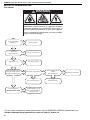
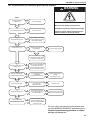
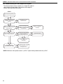
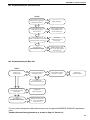
1
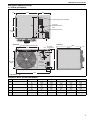
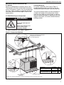
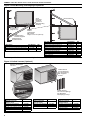
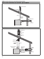
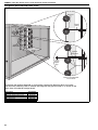
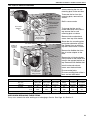
FOR YOUR SAFETY If you smell gas: 1. Open windows. 2. DO NOT try to light any appliance. 3. DO NOT use electrical switches. 4. DO NOT use any telephone in your building. 5. Leave the building. 6. Immediately call your local gas supplier after leaving the building. Follow the gas suppliers instructions. 7. If you cannot reach your gas supplier, call the Fire Department. WARNING C mbat ® Compact Tubular Unit Heaters Installation, Commissioning, Operation & Service Manual Models CTCU 7 CTCU 11 CTCU 15 CTCU 22 CTCU 27 CTCU 32 Fire Hazard Do not store or use petrol or other flammable vapours and liquids in the vicinity of this or any other appliance. Some objects will catch fire or explode when placed close to heater. Failure to follow these instructions can result in death, injury or property damage. WARNING Improper installation, adjustment, alteration, service or maintenance can result in death, injury or property damage. Read the installation, operation and service manual thoroughly before installing or servicing this equipment. Installation must be done by a registered installer/ contractor qualified in the installation and service of gas-fired heating equipment or your gas supplier. Quality in Any Language™ © Copyright 2006 Roberts-Gordon, LLC Installer Please take the time to read and understand these instructions prior to any installation. Installer must give a copy of this manual to the owner. Owner Keep this manual in a safe place in order to provide your serviceman with necessary information. Roberts-Gordon Europe Limited Oxford Street Bilston, West Midlands WV14 7EG UK Telephone: +44(0) 1902 494425 Fax: +44(0) 1902 403200 Service Telephone: +44(0) 1902 498733 Service Fax: +44(0) 1902 401464 E-mail: [email protected] E-mail: [email protected] www.rg-inc.com P/N 111100UK Rev B 10/06 TABLE OF CONTENTS SECTION 1: Heater Safety...................................................... 2 SECTION 2: Installer Responsibility ..................................... 2 2.1 Clearances to Combustibles ........................................ 2 2.2 Corrosive Chemicals.................................................... 2 2.3 National Standards and Applicable Codes .................. 2 SECTION 3: Critical Considerations ..................................... 3 3.1 Basic Information ......................................................... 3 3.2 Location and Suspension ............................................ 3 3.3 Minimum Required Installation Clearances ................. 3 3.4 Clearances to Combustibles ........................................ 3 3.5 Ventilation .................................................................... 3 3.6 Gas Supply .................................................................. 3 3.7 Electrical Supply .......................................................... 3 3.8 Flue.............................................................................. 3 SECTION 4: Specifications .................................................... 5 4.1 CTCUA (All Models) .................................................... 5 4.2 General Technical Data Table (All Models) .................. 6 4.3 Technical Data Table (All Models)................................ 6 SECTION 5: Heater Installation.............................................. 7 5.1 General ........................................................................ 7 5.2 Shelf Mounting and Suspension .................................. 7 5.3 Wall Mounting .............................................................. 7 SECTION 6: Flue Installation ................................................. 9 6.1 Changing Flue and Air Intake Orientation.................... 9 6.2 Flue Installation............................................................ 9 6.3 Type C12, C32 & C62 Appliance ...................................... 9 6.4 Type B22 Appliance....................................................... 9 SECTION 7: Air Supply......................................................... 11 7.1 Room Sealed Installation ........................................... 11 7.2 Open Flued Installation .............................................. 11 7.3 Building Ventilation ..................................................... 11 SECTION 8: Gas Piping ........................................................ 12 8.1 Connections............................................................... 12 SECTION 9: Wiring and Electrical Information................... 13 9.1 Electrical Supply ........................................................ 13 9.2 Remote Controls ........................................................ 13 9.3 CTCUA Wiring Diagram Models 7 - 32 ...................... 14 SECTION 10: Commissioning .............................................. 15 10.1 Pre-Commission Checks.......................................... 15 10.2 Begin Commissioning .............................................. 15 10.3 Complete the Commissioning .................................. 17 SECTION 11: User Instructions............................................ 18 11.1 User Instructions....................................................... 18 11.2 Heater Operation ...................................................... 18 11.3 Common User Controls ............................................ 18 11.4 Lighting Instructions.................................................. 18 11.5 Simple Fault Finding ................................................. 19 SECTION 12: Servicing......................................................... 20 12.1 Servicing Instructions .............................................. 20 12.2 Burner Maintenance ................................................ 20 12.3 Fan/Motor Assembly Maintenance........................... 20 12.4 Heat Exchanger Maintenance.................................. 20 12.5 Gas Control Valve Maintenance............................... 20 12.6 Flue Fan................................................................... 20 SECTION 13: Conversion Between Gases ..........................21 13.1 General ....................................................................21 13.2 Burner Conversion ...................................................21 13.3 Gas Valves ...............................................................21 SECTION 14: Troubleshooting .............................................22 14.1 General ....................................................................22 14.2 Troubleshooting For Automatic Ignition Burner Systems .......................................................23 14.3 Troubleshooting for Flame Supervision System .......24 14.4 Troubleshooting for Solenoid Valves ........................25 14.5 Troubleshooting for Main Fan ...................................25 SECTION 15: Removal and Replacement Parts..................26 15.1 Gas Valve .................................................................26 15.2 Burner Compartment ...............................................27 15.3 Ignition Electrode and Flame Probe .........................28 15.4 Flue Fan Vertical Installation ....................................29 15.5 Pressure Switch........................................................30 15.6 Ignition Control .........................................................31 15.7 CTCUA Axial Fan/Guard/Motor Assembly ...............31 15.8 Fan and Limit Thermostats ......................................31 © 2006 Roberts-Gordon, LLC All rights reserved. No part of this work covered by the copyrights herein may be reproduced or copied in any form or by any means - graphic, electronic, or mechanical, including photocopying, recording, taping or information storage and retrieval systems - without the written permission of Roberts-Gordon, LLC. Printed in U.S.A. TABLE OF FIGURES Figure 1: Installation Clearances and Clearances to Combustibles.............................................................. 4 Figure 2: Suspension Methods ................................................. 7 Figure 3: Shelf Mounting and Hanging Suspension.................. 8 Figure 4: Vertical Louvres (Optional) ........................................ 8 Figure 5: Flue and Roof Detail .................................................. 9 Figure 6: Vertical and Horizontal Flue Termination Type B22 Appliance ................................................... 10 Figure 7: Vertical and Horizontal Flue Termination Type C12 C32 & C62 Appliances.................................. 10 Figure 8: Gas Connection with Stainless Steel Flex Connector ......................................................... 12 Figure 9: Automatic Burner Control Box Sequence ................ 16 Figure 10: Gas Valve for Heater Models 7 - 32 ....................... 16 Figure 11: Heater Operating Sequence................................... 18 COMBAT® Compact Tubular Unit Heaters are high efficiency heaters and are listed on the Enhanced Capital Allowance Scheme ’Energy Technology Product List’. The ETL symbol is a UK registered certification mark of The Carbon Trust. Product Approval ROBERTS GORDON® appliances have been tested and CE certified as complying with the essential requirements of the Gas Appliance Directive, the Low Voltage Directive, the Electromagnetic Compatibility Directive and the Machinery Directive for use on natural gas and LPG when installed, commissioned and maintained in accordance with these instructions. These instructions refer to appliances designed to operate in the European Union. Appliances designed for other countries (non European Union) are available on request. This appliance must be installed in accordance with the local and national codes in force and used only in a sufficiently ventilated space, as specified in these instructions. Before installation, check that the local gas distribution systems, nature of gas and pressure, and adjustment of the appliance are compatible. 1 COMBAT® CTCU UNIT HEATER INSTALLATION OPERATION AND SERVICE MANUAL SECTION 1: HEATER SAFETY Your Safety is Important to Us! This symbol is used throughout the manual to notify you of possible fire, electrical or burn hazards. Please pay special attention when reading and following the warnings in these sections. clearances to combustibles. Affix the tag on a wall near the heater. 2.2 Corrosive Chemicals CAUTION Installation, service and annual inspection of heater must be done by a registered installer/contractor qualified in the installation and service of gas-fired heating equipment. Do not use heater in an area containing corrosive chemicals. Read this manual carefully before installation, operation, or service of this equipment. Failure to follow these instructions can result in property damage. This heater is designed for heating non-residential indoor spaces. Do not install in residential spaces. These instructions, the layout drawing, local codes and ordinances and applicable standards that apply to gas piping, electrical wiring, venting, etc. must be thoroughly understood before proceeding with the installation. SECTION 2: INSTALLER RESPONSIBILITY • To install the heater, as well as the gas and electrical supplies, in accordance with applicable specifications and codes. Roberts-Gordon recommends the installer contact a local building inspector, Fire Officer or insurance company for guidance. • To use the information given in the manual together with the local and national codes to perform the installation. • To install the heater in accordance with the clearances to combustibles of this heater. • To furnish all needed materials not furnished as standard equipment. • To plan location of supports, flues and air intakes. • To provide access to burners for servicing. • To provide the owner with a copy of this Installation, Commissioning, Operation and Service Manual. • To never use heater as support for ladder or other access equipment and never hang or suspend anything from heater. • To ensure that there is sufficient ventilation in the area to comply with the requirements of all relevant local and national codes. 2.1 Clearances to Combustibles In all situations, clearances to combustibles must be maintained. Caution must be used when running the heater near combustible materials such as wood, paper, rubber, etc. A wall tag is on the back cover of this manual as a permanent reminder of the safety instructions and the importance of the required 2 Corrosive chemicals will damage the burner and heat exchanger parts. Roberts-Gordon cannot be responsible for ensuring that all appropriate safety measures are undertaken prior to installation; this is entirely the responsibility of the installer. It is essential that the contractor, the sub-contractor, or the owner identifies the presence of combustible materials, corrosive chemicals or halogenated hydrocarbons* anywhere in the premises. * Halogenated Hydrocarbons are a family of chemical compounds characterized by the presence of halogen elements (fluorine, chlorine, bromine, etc.). These compounds are frequently used in refrigerants, cleaning agents, solvents, etc. If these compounds enter the air supply of the burner, the lifespan of the heater components will be greatly reduced. Warranty will be invalid if the heater is exposed to halogenated hydrocarbons. 2.3 National Standards and Applicable Codes All appliances must be installed in accordance with the latest revision of applicable standards and local and national codes. This refers also to the electric, gas and venting installation. Note: Additional standards for installations in public garages, aircraft hangars, etc. may be applicable. SECTION 3: CRITICAL CONSIDERATIONS SECTION 3: CRITICAL CONSIDERATIONS 3.1 Basic Information CTCU heaters have automatic ignition burners for ON/OFF operation only. 3.8 Flue Choose heater siting to allow for the proper location of the flue. Each heater must be fitted with an individual and correctly sized sealed flue system (See Page 9, Section 6). 3.2 Location and Suspension No other appliance may be connected to the flue. All models: For room sealed installation, the air intake must be • Must be installed indoors. the same size sealed system and the flue/air intake • Must be installed in a level position with horizonmust terminate at an approved concentric wall or tal or vertical discharge. roof terminal. • May be mounted on a shelf of non-combustible material. (See Page 5, Section 4 and Page 7, Figure 2 for support points.) • May be suspended from above (See Page 7, Figure 2) or from wall brackets of sufficient strength to support the heater as listed in the Dimension Data Table on Page 5, Section 4.1. Drop rods must be a minimum of 10 mm diameter mild steel. Four suspension points (M10 nuts) are located on top and back side of the heater. • Must be installed in a manner which allows access to all serviceable components. 3.3 Minimum Required Installation Clearances Clearances around the heater and flue must be as indicated on Page 4, Figure 1; Page 9, Figure 5 through Page 10, Figure 7 to ensure access for servicing, and correct operation. 3.4 Clearances to Combustibles Clearances must be as indicated on Page 4, Figure 1. If clearances to combustibles are not indicated, then installation clearances apply. 3.5 Ventilation It is important to ensure that there is adequate air circulation around the heater to supply air for combustion, ventilation and distribution in accordance with local and national codes. 3.6 Gas Supply It is important that the gas supply pipe is sized correctly to provide the inlet pressure as stated on the heater data plate. The gas supply pipe and electrical connections must not support any of the heater's weight. 3.7 Electrical Supply A permanent 230 V 50 Hz 1 Ø electrical supply is required at the main electrical terminals. The heater also requires suitable energy controls in accordance with Section 9. 3 COMBAT® CTCU UNIT HEATER INSTALLATION OPERATION AND SERVICE MANUAL WARNING Fire Hazard Some objects will catch fire or explode when placed close to heater. Keep all flammable objects, liquids and vapours the required distance away from the heater. Failure to follow these instructions can result in death, injury or property damage. Figure 1: Installation Clearances and Clearances to Combustibles Installation Clearances Roof Terminal Roof Terminal Air Intake Clearances to Combustibles 15 cm 15 cm 50 cm** Wall Terminal Flue 10 cm 3m 25 cm 30 cm 2.5 - 3.5 m* 3m * Heaters may be mounted at a higher level if destratification **80 cm is necessary to service fans are installed. heater. The heater must always be installed at least 1.8 m above the floor. The flue pipe must have clearance from combustibles by 5 cm. If installed at low levels where individuals can come in contact with hot heat exchanger components, adequate guarding must be provided. All distances are minimum clearance requirements for service access, air flow and safety. 4 SECTION 4: SPECIFICATIONS SECTION 4: SPECIFICATIONS 4.1 CTCUA (All Models) Top View 14 448 265 4 x M10 Captive Nuts Provided 422 Air Intake (Optional Position) 463 Flue (Optional Position) 120 Mounting Holes C 171 Rear View End View 4 x M10 Captive Nuts Provided Air Intake Flue on Model 22 448 660 514 D 120* 171 B A Air Intake Electrical Connection Lockout Reset Gas Supply Mounting Holes 45 85 728 * 140 for 27 - 32 Dimension Data - CTCUA (All Models) A Height B Mounting Hole Spacing C Centre of Flue (Top Option) D Centre of Flue Weight Model CTCU-7 CTCU-11 CTCU-15 CTCU-22 CTCU-27 / 32 mm (in) mm (in) mm (in) mm (in) 304 (12.0) 239 (9.4) 151 (5.9) 68 (2.7) 304 (12.0) 239 (9.4) 151 (5.9) 68 (2.7) 450 (17.7) 385 (15.2) 151 (5.9) 68 (2.7) 450 (17.7) 385 (15.2) 172 (6.8) 46 (1.8) 578 (22.8) 513 (20.2) 149 (5.9) 59 (2.3) kg 28 30.5 38.5 41 52.3 5 COMBAT® CTCU UNIT HEATER INSTALLATION OPERATION AND SERVICE MANUAL 4.2 General Technical Data Table (All Models) Model CTCU-7 CTCU-11 CTCU-15 CTCU-22 CTCU-27 / 32 Total Electrical Load W 260 274 336 384 345 Run Current A 1.1 1.2 1.5 1.7 1.5 Start Current A 1.7 1.8 2.5 2.9 2.6 Air Flow m3/h 1120 1220 2710 2750 4474 Sound Pressure Level at 3 m [NR] dB(A) [31] 37 [35] 41 [39] 45 [42] 48 [42] 48 mm Ø 80 80 80 80 100 m 2.5 4 5 5 5 CTCUA, Axial Fans Flue and AIr Intake Flue and Air Intake Size *Maximum Straight Flue/Air Intake Electrical load at 230 V 50 Hz measured by calculating from total run current of appliance. * Do not exceed the maximum length of flue stated or heater may not operate properly. Reduce the maximum length stated by 1 m for each 90° bend installed. **If minimum air flow requirements are not met, then temperature limit devices will shut down the heater. 4.3 Technical Data Table (All Models) Appliance Category II 2H/L 3B/P Model CTCU-7 CTCU-11 CTCU-15 CTCU-22 CTCU-27 CTCU-32 Heat Input Gross CV kW (Btu/h) x (1000) 8.5 29 13.4 46 18.3 62 27.5 94 33 113 38.5 131 Heat Input Net CV kW (Btu/h) x (1000) 7.7 26 12.1 41 16.5 56 24.8 85 29.7 101 34.7 118 Approximate Heat Output kW (Btu/h) x (1000) 7.1 24 11.1 38 15.1 52 23 78 27.2 93 31.7 108 Natural Gas (G20) Data - Inlet Pressure 20 mbar (7.8 in WG) Min. 17 mbar (6.8 in WG) Max. 25 mbar (10 in WG) Burner Pressure mbar 9.5 9.5 9.5 9.5 9.0 9.0 Gas Rate m3/h ft3/h 0.8 29 1.3 45 1.7 62 2.6 93 3.1 110 3.6 127 Natural Gas (G25) Data - Inlet Pressure 25 mbar (10 in WG) Min. 20 mbar (7.8 in WG) Max. 30 mbar (12 in WG) Burner Pressure mbar 9.0 9.0 9.5 9.2 9.2 9.3 Gas Rate m3/h ft3/h 0.9 33 1.5 52 2.0 72 3 108 3.6 127 4.2 148 LPG / Propane (G31) Data - Inlet Pressure 37 mbar (14.6 WG) Min. 25 mbar (10 in WG) Max. 45 mbar (18 in WG) Alternative where permitted 50 mbar (20 in WG) Min. 42.5 bar (17 in WG) Max. 57.5 mbar (23 in WG) Burner Pressure mbar 25.6 29.4 29.4 28.6 29.9 29.9 Gas Rate m3/h kg3/h 0.3 0.16 0.5 0.25 0.7 0.34 1 0.51 1.2 .61 1.4 .71 LPG / Butane (G30) Data - Inlet Pressure 29 mbar (11,4 in WG) Min. 20 mbar (7.8 in WG) Max. 35 mbar (13.8 WG) Burner Pressure mbar 19.2 21.9 22.9 21.4 21.4 22.4 Gas Rate m3/h kg3/h 0.2 0.09 0.4 0.14 0.5 0.19 0.8 0.29 .9 .34 1.1 .42 Gas rates corrected to standard conditions 1013.25 mbar 15° C. 6 SECTION 5: HEATER INSTALLATION SECTION 5: HEATER INSTALLATION 5.1 General Heaters are designed for installation above 1.8 m. These heaters must be installed within the heated space. Duct delivery systems are not permitted with axial fans. When handling or supporting the heater from below, ensure that the weight is taken at the support points. 5.2 Shelf Mounting and Suspension WARNING 5.3 Wall Mounting For typical suspension, See Page 8, Figure 3. Heaters blowing parallel to the wall can only be installed with the service door away from the wall. The wall mounting brackets must be attached to a suitable wall through all mounting holes. Screw sizes less than M10 may not be used. In order for the wall mounting brackets to adequately carry the weight of the heater, it must be installed with best building practice. Crush Hazard Use 10 mm steel drop rod minimum. Failure of the supports can result in death, injury or property damage. For typical suspension, See Page 7, Figure 2. Figure 2: Suspension Methods Unistrut Channel Nut Ensure all suspension hardware is torqued to a minimum of 27 Nm (20 ft lbs). Washer Nut 10 mm Steel Drop Rod Cone Point Set Pin Window Clamp 10 mm Steel Drop Rod Unistrut Nut Washer Description Part Number Shelf Mounting Bracket 11111510K Kit Shelf Mounting Bracket (2) 111111510 Screw #10 x 1/2" 94311008 Type AB Phil HWH Z (2) Riv Nut Shelf Mounting Brackets Qty. 2 2 Support Points NOTE: For vertical installations, use the mounting points on the rear of the unit. Existing cabinet screws must be re-used. 7 COMBAT® CTCU UNIT HEATER INSTALLATION OPERATION AND SERVICE MANUAL Figure 3: Shelf Mounting and Hanging Suspension Shelf Mounting Hanging Shelf Mounting Brackets (Fasten to Wall Mounting Bracket) Wall Mounting Bracket Arm (Right & Left) Wall Mounting Bracket Diagonal Wall Mounting Bracket Vertical Description Wall Shelf Mounting Bracket Kit Wall Suspension Mounting Bracket Kit Shelf Mounting Bracket Kit M10 Fasteners M8 Bolt Washer Lock Washer M8 Locknut Torque to 4.5 Nm (40 in lb) Part Number 11111512K 1111510K 11111511K Qty. 1 1 1 Description Wall Suspension Mounting Bracket Kit Wall Mounting Bracket Arm Left Wall Mounting Bracket Arm Right Wall Mounting Bracket Vertical Wall Mounting Bracket Diagonal M8 x 85 mm Hex Head Bolt M8 Lock Nut with Nylon Insert M8 Flat Washer M8 Lockwasher Part Number 11111511K 111WALL1L 111WALL1R 111WAL2 111WAL3 97311405 92204504 95204502 96404502 Qty. 1 1 1 2 2 6 6 6 6 Hardware provided to construct mounting bracket assembly only. Figure 4: Vertical Louvres (Optional) Remove Horizontal Louvres Install Vertical Louvre Brackets (top and bottom) with supplied screws. Install Vertical Louvres and Springs into Brackets with Springs at Top Push in Louvre and compress spring to remove (opposite end first) Description Vertical Louvre Kit CTCU 7 and 11 Vertical Louvre Bracket #10 Screw CTCU 7-11 Vertical Louvres Louver Spring Instruction Sheet Part Number 11111901K 11111903 S103 11111901 90901200 91040021 Description Vertical Louvre Kit CTCU 15 and 22 Vertical Louvre Bracket #10 Screw Instruction Sheet For models 15 and 22, horizontal louvres are re-used. 8 Part Number 11111900K 11111903 S103 91040021 Description Part Number Vertical Louvre Kit 11111902K CTCU 27 and 32 Vertical Louvre Bracket 11111903 #10 Screw S103 27-32 Vertical Louvre 11111902 Instruction Sheet 91040021 SECTION 6: FLUE INSTALLATION SECTION 6: FLUE INSTALLATION 6.1 Changing Flue and Air Intake Orientation The heater is sold with horizontal flue and fresh air connections as standard. If vertical flue and fresh air connections are required, follow the instructions on Page 29, Section 15.4. Figure 5: Flue and Roof Detail Flue Terminal 6.2 Flue Installation WARNING Masterflash Soaker Flashing or Rain Collar. Roof Fire Hazard Some objects will catch fire or explode when placed close to heater. Keep all flammable objects, liquids and vapours the required distance away from the heater. Failure to follow these instructions can result in death, injury or property damage. Metal Sleeve 25 mm Air Gap to Combustible Material Flue The flue must terminate outside of the building. Flues and air intakes must be a fully sealed system and correctly sized for the model. Flues should be assembled as detailed on Page 9, Figure 5 through Page 10, Figure 7. The joints between the flue terminal and the roof or wall must be properly sealed. If the flue passes through a wall or ceiling of combustible material it must be enclosed by a sleeve of non-combustible material and be separated from the sleeve by at least a 25 mm air gap. Flues and air intakes must be adequately supported so that the heater does not bear the weight of the pipes. For flue termination See Page 9, Figure 5 through Page 10, Figure 7. 6.3 Type C12, C32 & C62 Appliance Room Sealed. The heaters are designed to be installed as room sealed appliances. The flue and air intake are run as separate pipes to the special concentric wall or roof terminal. See Page 10, Figure 7. The wire mesh inside the fresh air adapter on the heater must be removed prior to installation. 6.4 Type B22 Appliance The flue must be fitted with a low resistance terminal. See Page 9, Figure 5 through Page 10, Figure 6. 9 COMBAT® CTCU UNIT HEATER INSTALLATION OPERATION AND SERVICE MANUAL Figure 6: Vertical and Horizontal Flue Termination - Type B22 Appliance Roof Terminal Masterflash Flue Vertical Option Masterflash Flue Horizontal Option Wall Terminal Figure 7: Vertical and Horizontal Flue Termination - Type C12 C32 & C62 Appliances Roof Terminal Plastic Cup Masterflash Manifold Air Intake Vertical Option Remove Internal Wire Mesh Flue Horizontal Option Wall Plate Flue Air Intake Remove Internal Wire Mesh 10 Manifold Wall Terminal SECTION 7: AIR SUPPLY SECTION 7: AIR SUPPLY 7.1 Room Sealed Installation When installed as a room sealed heater, the air for combustion is drawn in from outside the building. It is important to ensure that there is adequate ventilation to provide air for the distribution fan. 7.2 Open Flued Installation It is important to ensure that there is adequate air supply at all times for both combustion and heating requirements in accordance with local and national codes. 7.2.1 Heaters Installed Within the Heated Space Where the volume of the heated space is greater than 4.7 m3 per kilowatt of total rated heat input and the air change rate is at least 0.5/h, additional high and low level ventilation will not be required. For a building having an air change rate less than 0.5/h, ventilation will be necessary in accordance with local and national codes. Ventilation direct to outside must be provided as follows: • Heaters up to 70 kW heat input 5.0 cm2 per kW of rated heat input 7.3 Building Ventilation Where ventilation is required, air must be taken from an outside point where it is not likely to be contaminated or obstructed. Where natural ventilation is used, suitable ventilation with outside air at low level must be provided in accordance with Section 7.2.1 and local and national codes. Where mechanical ventilation is used, extract rate must be 5% - 10% less than the inlet rate. The mechanical ventilation must be interlocked with the burner on the CTCU heater. 11 COMBAT® CTCU UNIT HEATER INSTALLATION OPERATION AND SERVICE MANUAL SECTION 8: GAS PIPING WARNING Fire Hazard Connect gas supply according to Figure 8. Gas can leak if not installed properly. Failure to follow these instructions can result in death, injury or property damage. It is important that the gas supply pipe and the electrical connections do not support any of the heater’s weight. A gas meter is connected to the service pipe by the gas supply company. An existing meter should be checked, preferably by the company, to ensure that the meter is adequate for the rate of gas supply required. Installation pipes must be fitted in accordance with local and national codes. Pipe work from the meter to the heater(s) must be of adequate size. Pipes of smaller size than the heater inlet gas connection should not be used. 8.1 Connections Connect the heater to the gas supply ensuring that the final connections are as follows: • Gas supply pipe work is run in medium or heavy gauge tubing in compliance with local and national codes. • The gas supply pipe is adequately sized to carry the total volume of gas for the complete installation. • An isolating valve and union connection should be used and fitted into the supply adjacent to the heater. • For suspended heaters, use an approved metal flexible connection between the isolating valve and the heater. To reduce pressure loss, use one pipe size larger than the heater gas connection. IMPORTANT - The complete installation must be purged and tested for gas soundness in accordance with local and national codes. Figure 8: Gas Connection with Stainless Steel Flex Connector • Hold gas nipple securely with pipe wrench when attaching the flex gas connector. Option A: Stainless Steel Flex Gas Connector • Do not twist flexible gas connector. • Ensure all joints are gas tight. Do not bend flexible gas connector sharply. Gas Isolating Valve Option B: Medium or Heavy Gauge Tubing Gas Connector Drip Leg Union Connection 12 Cap SECTION 9: WIRING AND ELECTRICAL INFORMATION SECTION 9: WIRING AND ELECTRICAL INFORMATION 9.1 Electrical Supply 9.2.3 Remote Frost Thermostat All heater models need a constant 230 V 50 Hz 1 Ø When required, connect to L1 and T2 parallel to the supply connected to terminals L1, N & Earth. room thermostat. Locate within the heated space adjacent to the most vulnerable equipment that Polarity "L & N" must be correct. The voltage requires protection. See Page 14, Section 9.3. between neutral and earth should be 0 and never exceed 15 volts. 9.2.4 Remote Fan Controls All heaters and controls must be correctly earthed. The fan will operate automatically providing there is All external wiring must comply with the relevant a constant 230 V supply. local codes. Wire specification H05VV-F. A switch or control wired between L1 and T1 will External controls must have the same constant allow external control of the fan(s). 230 V 50 Hz supply. The fan may be controlled to operate continuously from an external control, with the burner cycling on An isolator with a contact separation of at least 3 mm on all poles must be installed adjacent to, but and off, providing that the fan run-on at close down not attached to, the heater to disconnect all supplies is not impaired. to the heater and any remote control. This switch should be fused to 5 A. The final connection to the heater should be made by flexible cable or conduit to the 7 pole plug using 1 mm2 cable on all models. WARNING Electrical Shock Hazard Disconnect electrical power before servicing. Failure to follow these instructions can result in death or electrical shock. 9.2 Remote Controls The heater is designed to be operated by controls installed remote from the heater. See Page 14, Section 9.3. 9.2.1 Burner Controls (Thermostat) Controls to operate the burner must be connected between L1 and T2. 9.2.2 Positioning Room Thermostats or ROBERTS GORDON® Control A room thermostat or ROBERTS GORDON® control should be mounted on a wall or column at a height of approximately 1.5 metres from the floor to measure the ambient temperature. It should be clear of both cold draughts and the direct path of warm air from the heater. 13 COMBAT® CTCU UNIT HEATER INSTALLATION OPERATION AND SERVICE MANUAL 9.3 CTCUA Wiring Diagram Models 7 - 32 12 GAS T1 N N 9 8 WHITE YELLOW BLACK WHITE 7 6 BLACK PRESSURE SWITCH 5 L1 L1 GREEN/YELLOW YELLOW IGNITION CONTROL T2 T1 10 S3 T2 BROWN 4 GROUND AT LIMIT 3 PINK 2 PURPLE 4 2 5 GREY 1 1 LOCKOUT RESET WITH INDICATOR LIGHT THERMOSTAT LINE GROUND REMOTE FAN ON NEUTRAL THERMOSTAT 230 V 50 Hz SUPPLY FAN DELAY THERMOSTAT EMC FILTER NOTE: If any of the original wire supplied with the heater must be replaced, it must be replaced with wiring material having a temperature rating of at least 105° C and 600 volts. 14 BLACK BLACK BROWN AXIAL FAN IGNITION CONTROL E N COMBUSTION FAN L E N L BLUE BROWN BLUE RED BLACK 7 POLE SOCKET LIMIT THERMOSTAT BROWN IGNITION SENSE REMOTE LOCKOUT RESET REMOTE LOCKOUT INDICATION 7 POLE PLUG 11 B4 BROWN B4 BLUE S3 VALVE SITE WIRING SECTION 10: COMMISSIONING SECTION 10: COMMISSIONING Installation, service, commissioning and annual inspection of the heater must be done by a contractor qualified in the installation and service of gas-fired heating equipment. Read this manual carefully before installation, commissioning, operation, or service of this equipment. All components are accessed via the door secured by 4 sheet metal screws. Opening the door exposes live electrical connections and hot components. WARNING Electrical Shock Hazard Use extreme caution while commissioning. Failure to follow these instructions can result in death or electrical shock. 10.1 Pre-Commission Checks All pre-commission checks must be carried out before lighting the heater. Ensure that the heater and all controls are suitable for the gas, pressure and electrical supply to which they are to be connected. 10.1.1 Louvres Where fitted, the air delivery louvres need to be set during commissioning to give the required air distribution (optional vertical louvres). 1. Check that all site wiring is connected in accordance with the appropriate wiring diagram on Page 14, Section 9.3. 2. Check the correct fuse size is fitted; See Page 13, Section 9.1. 10.1.3 Gas Supply All aspects of the gas installation including the gas meter must be inspected, tested for soundness and purged in accordance with local and national codes. Ensure that the air is fully purged from the heater inlet pipe up to the main gas valve inlet test nipple. 10.1.4 Mechanical Checks 1. Check that the fan is free to run and delivery louvres are turned to give required air deflection. 2. Check that the flue (and air intake for room sealed) is installed in accordance with these instructions and local regulations. NOTE: The limit thermostat is sealed at the factory and is not adjustable. 10.2 Begin Commissioning 10.2.1 Before Operating the Heater To ensure that all the controls are in safe working order, operate the heater for the first time with the isolating gas valve turned off. 1. Turn off the isolating gas valve. 2. Using the installed external control, turn on the burner. The automatic sequence will now begin as described on Page 16, Figure 9. There will be no ignition of the burner and lockout will occur, which proves the controls are operating correctly. WARNING Cut Hazard Turn off gas and electrical supply before maintenance. Fan can start automatically at any time. Failure to follow these instructions can result in severe injury or product damage. 10.1.2 Electrical Checks All pre-commission checks must be carried out before commissioning the heater. 15 COMBAT® CTCU UNIT HEATER INSTALLATION OPERATION AND SERVICE MANUAL Figure 9: Automatic Burner Control Box Sequence Burner sequence for Honeywell S4565C RUN START CLOSE DOWN Supply 230 V Flue Fan Pressure Switch P NO C 30 Sec. Purge* NC ts = 10 seconds Ignition Spark Start Gas Valve Flame Signal *Purge time begins at pressure switch change over. Required Incoming Signals Signals Output By Control If at any stage the flame fails, the control will go into "lockout". The red light inside the RESET switch will illuminate and the control will need to be manually reset before any further start attempt can be made. Figure 10: Gas Valve for Heater Models 7 - 32 End View Screw Ignition Output Flame Probe Connection Ignition Control (Plugs into Gas Valve) Regulator (Under Cover) 12 Cable Connector Outlet Pressure Inlet Pressure Gas Inlet 16 SECTION 10: COMMISSIONING 10.2.2 Commissioning the Gas Valve (All Gases) 10.2.2.1 Check Burner Gas Pressure 1. Loosen the screw cover of the outlet (burner) pressure test point and connect a manometer. 2. With the burner firing, measure the pressure on the manometer. To adjust the burner pressure, remove the regulator cover from the valve and turn the regulator adjustment screw to set the required burner pressure as stated in the Technical Data Tables for the correct gas and model on Page 6, Section 4.3. NOTE: If the correct burner pressure cannot be reached, then check the inlet pressure to the valve, with the burner firing. See Technical Data Tables on Page 6, Section 4.3 for inlet pressure requirement. Do not continue to adjust the regulator if the pressure is not changing. If the inlet pressure is too low to allow correct burner pressure setting, then the gas inlet pressure must be corrected before completing the commission. Check Gas Rate 1. After burner pressure adjustment, allow the heater to operate for at least 15 minutes and then re-check settings. 2. Remove the manometer and refit all covers to the valve and tighten the screw of the outlet pressure tap. 3. Check gas flow rate at gas meter. 10.2.5 Turning Off the Heater Set the external controls to the "OFF" position and the main burner will stop. The fan will run until it is stopped automatically by the fan thermostat. Do not use Electrical Isolator for control of heater. Electrical Isolator will switch off the fan. Heat exchanger could be damaged. Warranty will not cover damage to the heat exchanger if operated improperly. 10.2.6 External Controls External Controls may include time switch, room thermostat and frost thermostat. Operate each control to ensure that they function correctly. Set the time switch (if fitted) and room thermostat to the users’ requirements. 10.3 Complete the Commissioning Ensure that all covers are fitted correctly and all test points are properly sealed. 10.3.1 Instruction to the User Explain the controls of the heater to the user including how to turn it on and off, using the controls fitted on site. Give this manual to the user. Ensure that the user is shown and understands the importance of maintaining clearances to combustibles and the user instructions on Page 18, Section 11 through Page 19, Section 11.5 and all warnings defined in this manual. 10.2.3 Combustion Testing The only adjustment to alter combustion performance is burner pressure. Combustion quality must be tested to prove correct heater operation. Incorrect results will indicate faults with the installation or appliance. Combustion testing must be carried out with all covers in place. The flue gas is sampled in the flue, within 1 meter of the heater. The values of CO2 should be between 5.7% to 8.0% for natural gas and 6.8% to 9.2% for LPG dependant upon model. The CO will be up to 80 ppm (0.008%) dry, air free dependant upon model. Temperature rise of the flue gases above ambient should be approximately 130° C to 160° C. Seal test hole in flue after testing. 10.2.4 Pressure Switch The pressure switch is factory pre-set for each model and is not adjustable. 17 COMBAT® CTCU UNIT HEATER INSTALLATION OPERATION AND SERVICE MANUAL SECTION 11: USER INSTRUCTIONS 11.1 User Instructions The CTCU heaters are fully automatic and operate from the external controls fitted on site. The only user controls at the heater are the: Burner Lockout Reset Button ................ See Page 18, Section 11.3.3 Limit Thermostat Reset See Page 18, Section 11.3.2 Press to reset These are hand reset devices to give further protection against fan failure. NOTE: To reset, the heat exchanger must be cool. WARNING Description Limit Thermostat Part Number 90412100 WARNING Electrical Shock Hazard Disconnect electrical power before servicing. Failure to follow these instructions can result in death or electrical shock. 11.2 Heater Operation When the heater has been switched on by the remote controls installed on site, the main burner will automatically turn on. The burner control box will control the safe ignition of the flame. All heaters require a constant gas and electricity supply which must not be interrupted during the normal operation of this heater. Figure 11: Heater Operating Sequence ON THERMOSTAT CALL FOR HEAT BURNER RUN FAN CLOSE DOWN ON ON 2-3 MINUTES RUN ON 11.3 Common User Controls 11.3.1 Fan Thermostat The fan thermostat is located inside the access door at the top of the heater. See Page 28, Section 15.3. This control ensures the heater does not blow cold air in the normal heating cycle. 11.3.2 Limit Thermostat The limit thermostat is located inside the access door of the heater. See Page 28, Section 15.3. This control protects the heat exchanger against overheating. 18 Explosion Hazard If control locks out, do not make more than 3 attempts to restart the heater. Dangerous gas mixtures can build up. The fault must be traced and repaired by a registered installer or service engineer. Failure to follow these instructions can result in death, injury or property damage. 11.3.3 Burner Lockout Reset Button The red warning light on the back of the heater will illuminate when the control has gone to lockout. This may be caused by flame failure. Press the reset button on the back of the heater (See Page 5, Section 4.1) or the remote reset if installed on site. 11.4 Lighting Instructions 11.4.1 To Turn On Heater 1. Ensure that the electrical and gas supplies to the heater are on. Check that the on site controls are “ON”. NOTE: The thermostat setting must be above the ambient temperature for the heater to operate. 2. The automatic firing sequence will begin as described on Page 16, Figure 9. The heater will now operate automatically under the control of the on site controls. Following long shut down periods, the control may go to lockout. See Page 18, Section 11.3.3. SECTION 11: USER INSTRUCTIONS 11.4.2 To Turn the Heater Off Set the installed remote controls to the "OFF" position. The burner will turn off immediately. The fan will continue to run for a few minutes. To restart, turn the control used above to "ON". 11.5 Simple Fault Finding Some possible reasons for the heater not operating are: 1. Gas supply not turned "ON". 2. Electricity supply not turned "ON". 3. The time and/or temperature controls are not "ON". 4. The limit thermostat may have operated. This may be caused by an interruption of the electrical supply or failure of the distribution fan. If the limit thermostat persistently operates, there is a fault which must be investigated by a contractor qualified in the installation and service of gas-fired heating equipment. 11.5.1 Simple Fault Finding (Burner Faults) If the burner fails to ignite for any reason, it will go to lockout. This will be indicated by the red light on the back of the heater or at the remote indicator (if fitted). 1. Press in and release the lockout reset button. If a remote reset is not fitted, a reset button is on the back of the heater. See Page 5, Section 4.1. FOR YOUR SAFETY If you smell gas: 1. Open windows. 2. DO NOT try to light any appliance. 3. DO NOT use electrical switches. 4. DO NOT use any telephone in your building. 5. Leave the building. 6. Immediately call your local gas supplier after leaving the building. Follow the gas suppliers instructions. 7. If you cannot reach your gas supplier, call the Fire Department. WARNING Fire Hazard Do not store or use petrol or other flammable vapours and liquids in the vicinity of this or any other appliance. Some objects will catch fire or explode when placed close to heater. Failure to follow these instructions can result in death, injury or property damage. Lockout should not occur during normal operation of the heater and indicates there is a fault condition which must be corrected. 19 COMBAT® CTCU UNIT HEATER INSTALLATION OPERATION AND SERVICE MANUAL SECTION 12: SERVICING 12.1 Servicing Instructions After commissioning, the heater will require maintenance to be carried out annually. If the heater is used in a dirty or dusty area, more frequent maintenance may be necessary. Installation Code and Annual Inspections: All installations and service of ROBERTS GORDON® products must be performed by a contractor qualified in the installation and service of gas-fired heating equipment and conform to all requirements set forth in the ROBERTS GORDON® manuals and all applicable governmental authorities pertaining to the installation, service and operation of the equipment. To help facilitate optimum performance and safety, Roberts-Gordon recommends that a qualified contractor annually inspect your ROBERTS GORDON® products and perform service where necessary, using only ROBERTS GORDON® replacement parts. WARNING Cut Hazard Turn off gas and electrical supply before maintenance. Fan can start automatically at any time. Failure to follow these instructions can result in severe injury or product damage. NOTE 1: After any maintenance or repair work, always test fire the heater in accordance with the commissioning instructions on Page 15, Section 10 through Page 17, Section 10.3.1 to ensure all safety systems are in working order before leaving the heater to operate. Minor faults may be traced by using the troubleshooting charts on Page 22, Section 14 through Page 25, Section 14.5. NOTE 2: Check all gas pipes and pipe joints to ensure there are no cracks or gas leaks. Any cracks in the pipes or pipe joints must be repaired. NOTE 3: Inspect all suspended components and hardware. Insure that they are in good condition, properly tightened, and corrosion free. 12.2 Burner Maintenance 1. Open the door and remove the burner compartment cover. See Page 27, Section 15.2. 20 2. Clean any deposits from the main burner which may have formed in the injectors or venturi of the burner. See Page 27, Section 15.2. 3. Remove the ignition electrode and flame probe. Check condition of ignition electrode and flame probe. Clean off any deposits which may have been formed, check condition of ceramic insulators. Replace as necessary. 12.3 Fan/Motor Assembly Maintenance The main fan bearings are permanently sealed and do not need lubrication. Before cleaning, turn off gas and electrical supply. Remove the fan and use a small brush or duster to clean the fan blades from each side. Replace fan when done. 12.4 Heat Exchanger Maintenance The heat exchanger will remain clean unless a problem has developed with combustion. Inspect the heat exchanger. Look for signs of overheating at the front tubes which may indicate burner over firing or persistently low air flows. 12.5 Gas Control Valve Maintenance No regular maintenance is required on this device. To change gas control valves, See Page 26, Step 15.1 and Page 30, Section 15.5. Do not repair or disassemble on site. Replace faulty gas valves with genuine ROBERTS GORDON® replacement parts. 12.6 Flue Fan The flue fan should not require maintenance. However, if the air pressure switch is causing burner lockout, then remove the flue fan from the vent box by unscrewing the three screws at the mounting plate. Remove the four screws attaching the mounting plate to the fan inlet (See Page 29, Section 15.4). Ensure that the fan is free to run and that the fan wheel is clean. SECTION 13: CONVERSION BETWEEN GASES SECTION 13: CONVERSION BETWEEN GASES 13.1 General Conversion between gases will require a change of burner injectors and the gas valve re-commissioning to the new conditions. 13.2 Burner Conversion Conversion of the burner assembly from one gas to the other is the same for all types of heaters. 1. Remove the burner compartment cover as shown on Page 27, Section 15.2. 2. Remove the 4 screws holding the manifold and pull out the manifold. 3. Remove inshot burners by rotating them and sliding out the bracket. 4. Remove the main burner injectors. 5. Replace with the injectors for the new gas ensuring a gas tight seal. 6. Refit all components in reverse order. 13.3 Gas Valves All gas valves used on the CTCU have pressure regulators that may be set to operate on natural gas or LPG. Conversion is carried out by re-setting the burner pressure to the value in the data table during commissioning. See Page 6, Section 4.3. Ensure that the gas inlet pressure to the heater is correct for the new gas, and that the gas supply has been purged of the old gas. 21 COMBAT® CTCU UNIT HEATER INSTALLATION OPERATION AND SERVICE MANUAL SECTION 14: TROUBLESHOOTING 14.1 General WARNING Explosion Hazard Installation must be done by a registered installer/ contractor qualified in the installation and service of gas-fired heating equipment or your gas supplier. Failure to follow these instructions can result in death, injury or property damage. Start Are gas & electrical supplies on? No Turn on supplies. Yes Use 14.2 to test burner. No Use 14.5 to test fan. Yes Is Red lockout warning light on? No Does the fan run? Yes Yes With external controls on, does the burner continue through the heating cycle? No Has burner Locked Out? No The limit thermostat has tripped. See Section 11.3.2. Yes Yes Use 14.2 to test burner. Replace axial fan. No Replace limit thermostat. Yes Heater Operating TROUBLESHOOT ENDS. No If problems persist, contact Roberts-Gordon Ltd. at Tel: +44 (0)1902 498733 www.rg-inc.com For your safety and optimum heater performance, use only ROBERTS GORDON® replacement parts. Conduct Commissioning procedure as shown on Page 15, Section 10. 22 SECTION 14: TROUBLESHOOTING 14.2 Troubleshooting For Automatic Ignition Burner Systems WARNING Start Are gas & electrical supplies on? No Turn on supplies. Electrical Shock Hazard Do not touch ignition components. Yes Voltage from ignition components is high. Are external controls on? No Turn on controls. Yes Press in lockout reset button on rear of heater or remote reset button if fitted. Failure to follow these instructions can result in death or electrical shock. Yes Is red lockout light on? No Does flue fan run? No Is 230 V supply at fan connections? Yes Flue fan faulty; replace No Burner control faulty or plug in connections faulty. Repair or replace as necessary Yes Does air pressure switch change over? No Check for too much flue/air inlet duct. Check for blockage in combustion air circuit. Check for faulty air pressure switch. See Section 15.5. Yes Wait 30 - 40 seconds. Is ignition spark operating? No Is HT lead okay and connected? Yes Is spark electrode okay? Ignition control faulty; replace. See Section 15.6. Yes Does the flame light? No Is the gas valve operating? To test valve, No See Section 14.4. Replace valve. Yes Is red lockout light on? Yes Is the flame current at least 1 µAmp DC when the flame lights? Yes Trace fault in supervision system. See Section 14.3. No Heater Operating TROUBLESHOOT ENDS. No If problems persist, contact Roberts-Gordon Ltd. at Tel: +44 (0) 1902 498733 www.rg-inc.com For your safety and optimum heater performance, use only ROBERTS GORDON® replacement parts. Conduct Commissioning procedure as shown on Page 15, Section 10. 23 COMBAT® CTCU UNIT HEATER INSTALLATION OPERATION AND SERVICE MANUAL 14.3 Troubleshooting for Flame Supervision System To measure flame current, connect a 0 - 50 μA DC meter in series with the flame probe. If the meter reads negative values, then reverse the test leads. START Connect a DC ammeter in series with the flame probe. Is the flame present and at least 1 µA DC flame current? No Use Section 14.1 to trace the fault. Yes Is there a current flowing in the flame probe circuit with no flame present? Yes Is the connecting lead damaged? Is the flame probe damaged or touching earthed components? Yes Repair or replace as necessary. Yes Is inlet burner gas pressure correct? Is live and neutral polarity correct? Is flame probe circuit correct? Yes Control box faulty. Replace with correct type. No Does lockout occur when there is a flame present? No Repair or replace as necessary. No Heater Operating TROUBLESHOOT ENDS. No If problems persist, contact Roberts-Gordon Ltd. at www.rg-inc.com NOTE: Minimum flame probe current 1 μA DC. Typical flame probe current 3-5 μA DC. 24 SECTION 14: TROUBLESHOOTING 14.4 Troubleshooting for Solenoid Valves START Is gas pressure at inlet of the valve correct for gas type? Note pressure found. No Fault elsewhere. No Valve or ignition control faulty. Replace with one of correct type. No Valve faulty. Replace with one of correct type. No If problems persist, contact Roberts-Gordon Ltd. at Tel: +44 (0) 1902 498733 www.rg-inc.com Yes Does gas pressure at outlet of the valve rise when valve turns on? Yes Yes Does gas pressure at outlet of valve return to zero or lower when valve turns off? Yes Valve Operating TROUBLESHOOT ENDS. 14.5 Troubleshooting for Main Fan START Does fan run automatically? No Is power supply 230 V at terminals T1 to N? No Is there 230 V between terminals L1 and N? Yes Replace fan delay thermostat. Yes Fan motor faulty. Replace with correct type. Yes Does fan turn on and off while burner is firing continously? Yes Replace fan delay thermostat. No If problems persist, contact Roberts-Gordon Ltd. at Tel: +44 (0) 1902 498733 www.rg-inc.com No Fan Operating TROUBLESHOOT ENDS. For your safety and optimum heater performance, use only genuine ROBERTS GORDON® replacement parts. Conduct Commissioning procedure as shown on Page 15, Section 10. 25 COMBAT® CTCU UNIT HEATER INSTALLATION OPERATION AND SERVICE MANUAL SECTION 15: REMOVAL AND REPLACEMENT PARTS See warnings and notes on Page 20, Section 12 before removing or replacing parts. Burner Components All serviceable burner parts are accessed by the door on the side of the heater. Remove the four sheetmetal screws. 15.1 Gas Valve Remove the gas supply pipe at the heater inlet. Disconnect wire harness Unplug control from valve. Remove fixing screw. Ignition Control Description Gas Valve VK4105A Ignition Control Replace in reverse order. Verify that the gas flow direction of the valve is correct. Use a minimum amount of gas seal on the thread joint. Check that all the joints are leak free. Reset gas valve. See Page 17, Section 10.2.2. IT IS IMPORTANT THAT ONLY THE CORRECT GAS VALVE IS USED WHEN REPLACING THESE CONTROLS. 26 Part Number 90033403 90434010 SECTION 15: REMOVAL AND REPLACEMENT PARTS 15.2 Burner Compartment Burner Compartment Cover Viewing Port Flame Probe Ignition Electrode The burner compartment is a sealed compartment. Following any work, re-seal the compartment with the gas pipe rubber seal fully in place and all screws fitted and tight. Remove flexible air duct from spigot. Remove screws and pull off burner cover. 15.2.1 Burner Injectors Manifold Remove manifold screws and pull out manifold. Ensure gas tight fitting of injectors. Ensure correct alignment with burners. Ensure all pipe joints are gas tight. Manifold Burners Unscrew Injectors Injectors Manifold Mounting Bracket Gromet Marking MODEL CTCU-7 CTCU-11 CTCU-15 CTCU-22 CTCU-27 CTCU-32 Injector Quantity 2 3 4 5 6 7 1.78 1.85 1.85 2.06 2.057 2.057 Natural Gas (G20) Injector size mm Ø 0.070 0.073 0.073 0.081 0.081 0.081 Marking in Ø 50 49 49 46 46 46 RG P/N 91930050 91930049 91930049 91930046 91930046 91930046 1.99 2.06 2.06 2.26 2.261 2.261 Natural Gas (G25) Injector size mm Ø 0.0785 0.081 0.081 0.089 0.089 0.089 Marking in Ø 47 46 46 43 43 43 RG P/N 91930047 91930046 91930046 91930043 91930043 91930043 1.18 1.18 1.18 1.25 1.25 1.25 0.0465 0.0465 0.0465 0.049 0.049 0.049 LPG Propane (G31) and LPG Butane (G30) Injector size mm Ø in Ø Marking 56 56 56 1.25 1.25 1.25 RG P/N 91930056 91930056 91930056 91930125 91930125 91930125 27 COMBAT® CTCU UNIT HEATER INSTALLATION OPERATION AND SERVICE MANUAL 15.3 Ignition Electrode and Flame Probe Burners Limit Thermostat Flame Probe Flame Probe Fan Thermostat Ignition Electrode Ignition Electrode .120 (3 mm) spark gap Burners Burner Compartment Front Views To replace the ignition electrode or flame probe, remove the electrical lead and screw. Pull out from mounting. Refit in reverse ensuring that the gap to burner is as shown in the front view of the burner compartment. Description Spark Electrode Automatic Ignition Flame Probe Burners Fan Thermostat Limit Thermostat 28 Part Number 90427411 90439300 92000002 90412102 90412100 SECTION 15: REMOVAL AND REPLACEMENT PARTS 15.4 Flue Fan Vertical Installation To remove the fan, remove 3 screws securing the fan and mounting plate to the vent box. Intake & Exhaust Covers Mounting Plate to Vent Box fixing screws Gaskets Air Intake Adapter Vent Box Mounting Plate to Flue Fan fixing screws Refit in reverse order. To change the flue and air intake orientation from back to top, remove the fan and mounting plate as above. Remove intake and exhaust covers from top of the heater. Rotate the fan, mounting plate and gasket clockwise until the flue adapter lines up with the top hole. Secure with 3 screws. Air Intake Adapter Intake & Exhaust Covers To remove the fan from the mounting plate, remove the 4 screws. Gasket Remove the flexible duct from the air intake adapter on the back. Flexible Duct Remove the air intake adapter from the back of the heater and install in the appropriate hole on top. Reconnect the flexible duct. Install intake and exhaust covers over the back holes. Mounting Plate to Vent Box fixing screws Ensure sealed joints. Ensure mounting plate orifice is clear and not obstructed. MODEL CTCU-7 CTCU-11 CTCU-15 CTCU-22 CTCU-27 CTCU-32 Flue Fan Fasco 7021-11767 Fasco 7021-11768 Fasco 7021-11769 Torin S6818 Sit Controls P1210838 Sit Controls P1210838 RG P/N 90710470 90710470 90710470 90710460 90710460 90710460 35 44 57 64 109.2 109.2 Air Plate mm Ø in Ø RG P/N 1.38 1.75 2.25 2.50 4.3 4.3 11111210 11112210 11113210 11114210 11115210 11115210 IT IS IMPORTANT THAT ONLY THE CORRECT FLUE FAN SPECIFIED FOR EACH MODEL TYPE IS USED WHEN REPLACING THESE ITEMS. Carry out a commission after working on or changing a flue fan. See Page 18, Section 11. 29 COMBAT® CTCU UNIT HEATER INSTALLATION OPERATION AND SERVICE MANUAL 15.5 Pressure Switch Pull off 3 way connector. Spring open plastic clips of mounting cradle. Replace with correct type of pressure switch for model. The pressure switches are colour coded for each pressure setting. WARNING Carbon Monoxide Hazard Use correct pressure switch specified for each model. Use of incorrect pressure switch could cause unsafe condition. Failure to follow these instructions can result in death or serious injury. Carry out a commission after working on or changing a pressure switch. See Page 15, Section 10. Pressure Switch CTCU-7 CTCU-11 CTCU-15 CTCU-22 CTCU-27 CTCU-32 RG P/N 90439812 90439812 90439812 90439803 90439803 90439803 Colour Code orange orange orange grey grey grey Set Point mbar 0.45 0.45 0.45 1.02 1.02 1.02 in wc 0.18 0.18 0.18 0.41 .041 .041 30 SECTION 15: REMOVAL AND REPLACEMENT PARTS 15.6 Ignition Control The control plugs onto the gas valve. Pull out 12 pin electrical connection. Pull out ignition cable and flame probe cable noting their positions Release screw securing control to gas valve. Refit in reverse. Ensure correct location of ignition and flame probe cables. Ensure that the earth connection is made directly to the earth point on the gas valve. 15.7 CTCUA Axial Fan/Guard/Motor Assembly The axial fan unit for the CTCUA heater is supplied completely assembled and balanced. 15.8 Fan and Limit Thermostats 15.8.1 Removal and Replacement 1. Pull off the electrical connections to the thermostat 2. Unscrew the two screws securing the thermostat 3. Fit a new thermostat with two screws ensuring that the correct temperature setting and type are selected. See Page 6, Section 4.3. 4. Reconnect the electrical connections and test operation. 15.7.1 Fan Removal and Replacement Remove the screws and washers. Description Axial Fan CTCU-7 Axial Fan CTCU-11 Axial Fan CTCU-15 Axial Fan CTCU-22 Axial Fan CTCU-27/32 Part Number 11111910 11111911 11111920 11111921 11111922 15.7.2 To Replace the Fan Assembly To replace the fan assembly, reverse the procedure shown above. Fit rubber washers to the guard mountings to reduce vibration. • Check that the fan blades are free to rotate before turning on the power to the fan. • Strictly comply with the colour code of the fan wires to ensure correct operation. See Page 14, Section 9.3 wiring diagram. • Use only genuine ROBERTS GORDON® replacement parts. 31 Attach this information to the wall near the ROBERTS GORDON® heater ® Read the installation, Commissioning, Operation and Service Manual thoroughly before installation, operation or service. WARNING OPERATING INSTRUCTIONS 1. STOP! Read all safety instructions on this information sheet. 2. Open the manual gas valve in the heater supply line. 3. Turn on electric power to the heater. 4. Set the thermostat to desired setting (above ambient temperature). The automatic starting sequence begins. NOTE: Following long shutdown periods, the burner control may go to to 'LOCKOUT' during the start sequence. Push the reset button to recommence firing. Contact service department if 'LOCKOUT' continues (see manual for details). TO TURN OFF THE HEATER 1. Turn the thermostat/time switch to 'OFF'. The burner will turn 'OFF' immediately, but fans will continue to cool heat exchanger until the fan thermostat switches off. IF THE HEATER WILL NOT OPERATE, TO ENSURE YOUR SAFETY, FOLLOW THESE INSTRUCTIONS TO SHUT DOWN YOUR HEATER 1. Set the thermostat to off or the lowest setting. 2. Turn off electric power to the heater. 3. Turn off the manual gas valve in the heater supply line. 4. Call your registered installer/contractor qualified in the installation and service of gas-fired heating equipment. Installation Clearances Some objects can catch fire or explode when placed close to heater. Keep all flammable objects, liquids and vapors the required clearances to combustibles away from heater. Failure to follow these instructions can result in death, injury or property damage. Clearances to Combustibles Roof Terminal Roof Terminal Air Intake Fire Hazard 15 cm 15 cm 50 cm** Wall Terminal Flue 25 cm 30 cm 2.5 - 3.5 m* 3m *Heaters may be mounted at a higher level if destratification fans are installed. Roberts-Gordon, LLC 1250 William Street P.O. Box 44 Buffalo, NY 14240-0044 USA Telephone: 716.852.4400 Fax: 716.852.0854 Toll Free: 800.828.7450 10 cm 3m Roberts-Gordon Europe Limited Oxford Street Bilston, West Midlands WV14 7EG UK Telephone: +44(0) 1902 494425 Fax: +44(0) 1902 403200 **80 cm is necessary to service heater Service Telephone: +44(0) 1902 498733 Service Fax: +44(0) 1902 401464 E-mail: [email protected] E-mail: [email protected] Installation Code and Annual Inspections: All installations and service of ROBERTS GORDON® products must be performed by a contractor qualified in the installation and service of products sold and supplied by Roberts-Gordon and conform to all requirements set forth in the ROBERTS GORDON® manuals and all applicable governmental authorities pertaining to the installation, service and operation of the equipment. To help facilitate optimum performance and safety, Roberts-Gordon recommends that a qualified contractor annually inspect your ROBERTS GORDON® products and perform service where necessary, using only ROBERTS GORDON® replacement parts. Further Information: Applications, engineering and detailed guidance on systems design, installation and product performance is available through ROBERTS GORDON® representatives. Please contact us for any further information you may require, including the Installation, Operation and Service Manual. This product is not for residential use. This document is intended to assist licensed professionals in the exercise of their professional judgement. © 2006 Roberts-Gordon, LLC All rights reserved. No part of this work covered by the copyrights herein may be reproduced or copied in any form or by any means graphic, electronic, or mechanical, including photocopying, recording, taping, or information storage and retrieval systems without written permission of Roberts-Gordon, LLC. www.rg-inc.com Printed in U.S.A.


![Roberts Gorden Combat UHA[X][S] 45 Service manual](http://vs1.manualzilla.com/store/data/007386195_1-bf35e0ff6fb7205a4728576e3a14e91b-150x150.png)