1
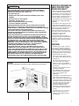
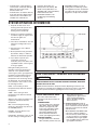
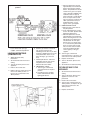
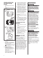
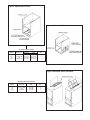
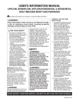
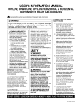
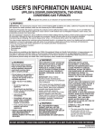
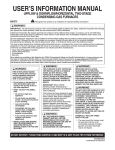
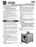
USER’S INFORMATION MANUAL
UPFLOW, DOWNFLOW, UPFLOW/HORIZONTAL & HORIZONTAL
ONLY INDUCED DRAFT GAS FURNACES
!
Recognize this symbol as an indication of Important Safety Information!
!
WARNING
If the information in this manual is not followed exactly,
a fire or explosion may result, causing property
damage, personal injury or loss of life.
!
FOR YOUR SAFETY
— Do not store or use gasoline or other
flammable vapors and liquids, or other
combustible materials in the vicinity of
this or any other appliance.
— WHAT TO DO IF YOU SMELL GAS
• Do not try to light any appliance.
• Do not touch any electrical switch;
do not use any phone in your
building.
• Immediately call your gas supplier
from a neighbor’s phone. Follow the
gas supplier’s instructions.
• If you cannot reach your gas
supplier, call the fire department.
• Do not rely on smell alone to detect
leaks. Due to various factors, you may
not be able to smell fuel gases.
• A U. L. recognized fuel gas and CO
detector(s) are recommended in all
applications, and their installation should
be in accordance with the
manufacturer’s recommendations and/or
local laws, rules, regulations or codes.
— Installation and service must be
performed by a qualified installer,
service agency or the gas supplier.
IMPORTANT: READ THESE
INSTRUCTIONS THOROUGHLY
BEFORE ATTEMPTING TO OPERATE
THIS FURNACE.
This furnace has been designed to
give you many years of efficient,
dependable home comfort. With
regular maintenance, this furnace will
operate satisfactorily year after year.
Please read this manual to familiarize
yourself with operation, routine
maintenance schedule, and safety
procedures.
!
WARNING
DEVICES ATTACHED TO THE FLUE
OR VENT FOR THE PURPOSE OF
REDUCING HEAT LOSS UP THE
CHIMNEY, INCLUDING FIELDINSTALLED DRAFT INDUCERS,
HAVE NOT BEEN TESTED AND
HAVE NOT BEEN INCLUDED IN THE
DESIGN CERTIFICATION OF THIS
FURNACE. WE, THE MANUFACTURER, CANNOT AND WILL NOT BE
RESPONSIBLE FOR INJURY OR
DAMAGE CAUSED BY THE USE OF
SUCH UNTESTED AND/OR
UNCERTIFIED DEVICES,
ACCESSORIES OR COMPONENTS.
SAFETY
!
WARNING
IMPROPER INSTALLATION,
ADJUSTMENT, ALTERATION,
SERVICE OR MAINTENANCE CAN
CAUSE PROPERTY DAMAGE,
PERSONAL INJURY OR DEATH.
FOR ASSISTANCE OR ADDITIONAL
INFORMATION CONSULT A
QUALIFIED INSTALLER, SERVICE
AGENCY OR THE GAS SUPPLIER.
!
WARNING
OBSTRUCTION OF THE AIR VENT
ON AN LP (PROPANE) TANK
REGULATOR CAN CAUSE
EXPLOSION OR FIRE RESULTING IN
PROPERTY DAMAGE, SEVERE
PERSONAL INJURY OR DEATH.
YOUR GAS SUPPLIER SHOULD
PERIODICALLY INSPECT AND
CLEAN THE AIR VENT SCREEN TO
PREVENT ANY OBSTRUCTION.
KEEP PROTECTIVE REGULATOR
COVER IN PLACE, AS EXPOSURE
TO THE ELEMENTS CAN CAUSE
ICE BUILDUP AND REGULATOR
FAILURE.
CAREFULLY FOLLOW THESE
SAFETY RULES:
1. Combustible material must not be
placed on or against the furnace
jacket. The area around the
furnace must be kept clear and
free of all combustible materials
including gasoline and other
flammable vapors and liquids.
2. A furnace installed in an attic or
other insulated space must be kept
free and clear of insulating
material. Examine the furnace area
when installing the furnace or
adding more insulation. Some
materials may be combustible.
3. To prevent carbon monoxide
poisoning, all blower doors and
compartment covers must be
replaced after the furnace is
serviced. Do not operate the unit
without all panels and doors
securely in place.
4. Should overheating occur, or the
gas valve fail to shut off the gas
supply, turn off the manual gas
valve to the furnace before turning
off the electrical supply.
5. Any additions, changes or
conversions required in order for
the furnace to satisfactorily meet
the application needs should be
made by a qualified installer,
service agency or the gas supplier,
using factory specified or approved
parts. Read your WARRANTY.
Contact the WARRANTOR for
conversion information. This
furnace was equipped at the
factory for use on NATURAL GAS
ONLY. Conversion to L.P. GAS
requires a special kit supplied by
the WARRANTOR.
6. A furnace needs an adequate
supply of combustion and
ventilation air for proper and safe
operation. Do not block or obstruct
air openings on the furnace or air
openings supplying the area where
the furnace is installed. Do not
store anything around the furnace
that could block the flow of fresh air
to the unit. Your installation may
DO NOT DESTROY. PLEASE READ CAREFULLY AND KEEP IN A SAFE PLACE FOR FUTURE REFERENCE.
92-20802-64-05
SUPERSEDES 92-20802-64-04
receive air from the inside heated
space., from the outside, from the
attic or crawl space. Whenever
adding insulation, be sure the air
supply openings are not covered.
any part of the control system and
any gas control which has been
under water.
7. Do not use this furnace if any part
has been under water. Immediately
call a qualified installer, service
agency or the gas supplier to
inspect the furnace and to replace
GENERAL INFORMATION
!
WARNING
DUCT LEAKS CAN CREATE AN
UNBALANCED SYSTEM AND DRAW
POLLUTANTS SUCH AS DIRT, DUST,
FUMES AND ODORS INTO THE
HOME CAUSING PROPERTY
DAMAGE. FUMES AND ODORS
FROM TOXIC, VOLATILE OR
FLAMMABLE CHEMICALS, AS WELL
AS AUTOMOBILE EXHAUST AND
CARBON MONOXIDE (CO), CAN BE
DRAWN INTO THE LIVING SPACE
THROUGH LEAKING DUCTS AND
UNBALANCED DUCT SYSTEMS
CAUSING PERSONAL INJURY OR
DEATH (SEE FIGURE 1).
• IF AIR-MOVING EQUIPMENT OR
DUCTWORK IS LOCATED IN
GARAGES OR OFF-GARAGE
STORAGE AREAS - ALL JOINTS,
SEAMS, AND OPENINGS IN THE
EQUIPMENT AND DUCT MUST BE
SEALED TO LIMIT THE
MIGRATION OF TOXIC FUMES
AND ODORS INCLUDING CARBON
MONOXIDE FROM MIGRATING
INTO THE LIVING SPACE.
2
• IF AIR-MOVING EQUIPMENT OR
DUCTWORK IS LOCATED IN
SPACES CONTAINING FUEL
BURNING APPLIANCES SUCH AS
WATER HEATERS OR BOILERS ALL JOINTS, SEAMS, AND
OPENINGS IN THE EQUIPMENT
AND DUCT MUST ALSO BE
SEALED TO PREVENT
DEPRESSURIZATION OF THE
SPACE AND POSSIBLE
MIGRATION OF COMBUSTION
BYPRODUCTS INCLUDING
CARBON MONOXIDE INTO THE
LIVING SPACE.
!
NOTICE
IMPROPER INSTALLATION, OR
INSTALLATION NOT MADE IN
ACCORDANCE WITH THE CSA
INTERNATIONAL (CSA)
CERTIFICATION OR THESE
INSTRUCTIONS, CAN RESULT IN
UNSATISFACTORY OPERATION
AND/OR DANGEROUS CONDI-TIONS
AND ARE NOT COVERED BY THE
UNIT WARRANTY.
!
NOTICE
IN COMPLIANCE WITH RECOGNIZED
CODES, IT IS RECOMMENDED THAT
AN AUXILIARY DRAIN PAN BE
INSTALLED UNDER ALL
EVAPORATOR COILS OR UNITS
CONTAINING EVAPORATOR COILS
THAT ARE LOCATED IN ANY AREA
OF A STRUCTURE WHERE DAMAGE
TO THE BUILDING OR BUILDING
CONTENTS MAY OCCUR AS A
RESULT OF AN OVERFLOW OF THE
COIL DRAIN PAN OR A STOPPAGE
IN THE PRIMARY CONDENSATE
DRAIN PIPING. SEE ACCESSORIES
SECTION OF THESE INSTRUCTIONS
FOR AUXILIARY HORIZONTAL
OVERFLOW PAN INFORMATION
(MODEL RXBM).
!
WARNING
CARBON MONOXIDE (CO) IS A COLORLESS, ODORLESS, POISONOUS
GAS THAT CAN CAUSE SEVERE PERSONAL INJURY OR DEATH.
CARBON MONOXIDE CAN BE PRODUCED BY ANY FUEL-BURNING
DEVICE, INCLUDING BUT NOT LIMITED TO:
• MOTOR VEHICLES
• GENERATORS AND OTHER GASOLINE POWERED TOOLS AND
ENGINES
• GAS AND FUEL-OIL APPLIANCES
• CHARCOAL OR GAS GRILLS
• WOOD OR GAS FIREPLACES AND STOVES
• OUTDOOR CAMPING EQUIPMENT
CARBON MONOXIDE FROM ANY ONE OF THESE DEVICES CAN BE
INADVERTENTLY DRAWN INTO AND DISTRIBUTED THROUGH THE
LIVING SPACE BY THE NORMAL OPERATION OF THE CENTRAL HEATING
/ AIR CONDITIONING SYSTEM (SEE FIGURE 1).
APPLIANCES AND FUEL BURNING DEVICES MUST BE INSTALLED,
OPERATED AND MAINTAINED IN ACCORDANCE WITH THE MANUFACTURER’S INSTRUCTIONS.
GASOLINE-POWERED TOOLS AND MOTOR VEHICLES MUST NOT BE
OPERATED IN ENCLOSED SPACES, SUCH AS BASEMENTS, CRAWLSPACES, OR GARAGES, EVEN WITH DOORS AND WINDOWS OR VENTS
OPEN, AS EXHAUST FUMES INCLUDING CARBON MONOXIDE CAN BUILD
UP AND SEEP INTO THE LIVING SPACE THROUGH CRACKS AND
OPENINGS IN THE STRUCTURE. TOXIC FUMES, INCLUDING CARBON
MONOXIDE, CAN ALSO BE DRAWN INTO THE LIVING SPACE THROUGH
OPENINGS AND SEAMS IN THE CENTRAL HEATING AND AIR
CONDITIONING EQUIPMENT AND / OR DUCTWORK.
FOR THESE REASONS, THE U.S. CONSUMER PRODUCT SAFETY
COMMISSION (CPSC) RECOMMENDS THAT EVERY HOME HAVE AT
LEAST ONE CARBON MONOXIDE ALARM INSTALLED IN THE HALLWAY
NEAR THE BEDROOMS IN EACH SEPARATE SLEEPING AREA OF THE
HOME. CARBON MONOXIDE ALARMS SHOULD BE CERTIFIED TO THE
REQUIREMENTS OF THE MOST RECENT UL, IAS OR CSA STANDARD,
AND SHOULD BE INSTALLED, OPERATED AND MAINTAINED IN
ACCORDANCE WITH THE ALARM MANUFACTURER’S INSTRUCTIONS.
FIGURE 1
MIGRATION OF DANGEROUS SUBSTANCES, FUMES, AND ODORS INTO LIVING SPACES
IMPORTANT INFORMATION
ABOUT EFFICIENCY AND
INDOOR AIR QUALITY
Central cooling and heating equipment
is only as efficient as the duct system
that carries the cooled or heated air. To
maintain efficiency, comfort and good
indoor air quality, it is important to have
the proper balance between the air
being supplied to each room and the air
returning to the cooling and heating
equipment.
Proper balance and sealing of the duct
system improves the efficiency of the
heating and air conditioning system and
improves the indoor air quality of the
home by reducing the amount of
airborne pollutants that enter homes
from spaces where the ductwork and /
or equipment is located. The
manufacturer and the U.S.
Environmental Protection Agency’s
Energy Star Program recommend that
central duct systems be checked by a
qualified contractor for proper balance
and sealing.
RECEIVING
Immediately upon receipt, all cartons
and contents should be inspected for
transit damage. Units with damaged
cartons should be opened immediately.
If damage is found, it should be noted
on the delivery papers, and a damage
claim filed with the last carrier.
• After unit has been delivered to job
site, remove carton taking care not to
damage unit.
• Check the unit rating plate for unit
size, electric heat, coil, voltage,
phase, etc. to be sure equipment
matches what is required for the job
specification.
• Read the entire instructions before
starting the installation.
• Some building codes require extra
cabinet insulation and gasketing
when unit is installed in attic
applications.
• If installed in an unconditioned space,
apply caulking around the power
wires, control wires, refrigerant tubing
and condensate line where they enter
the cabinet. Seal the power wires on
the inside where they exit conduit
opening. Caulking is required to
prevent air leakage into and
condensate from forming inside the
unit, control box, and on electrical
controls.
• Install the unit in such a way as to
allow necessary access to the
coil/filter rack and blower/control
compartment.
3
• Install the unit in a level position to
ensure proper condensate drainage.
Make sure unit is level in both
directions within 1/8”.
• Install the unit in accordance with any
local code which may apply and the
national codes. Latest editions are
available from: “National Fire
Protection Association, Inc.,
Batterymarch Park, Quincy, MA
02269.” These publications are:
• ANSI/NFPA No. 70-(Latest Edition)
National Electrical Code.
• NFPA90B Installation of warm air
heating and air conditioning systems.
• The equipment has been evaluated in
accordance with the Code of Federal
Regulations, Chapter XX, Part 3280.
• NFPA90A Installation of Air
Conditioning and Ventilating
Systems.
SYSTEM OPERATION INFORMATION
1. Keep the air filters clean. Your
heating system will operate more
efficiently and provide better
heating, more economically.
Figure 2. Burner Compartment, showing location of Gas Controls
2. Arrange your furniture and drapes
so that the supply air registers and
the return air grilles are
unobstructed.
3. Close doors and windows. This will
reduce the heating load on your
system.
4. Avoid excessive use of kitchen
exhaust fans.
5. Do not permit the heat generated
by television, lamps, or radios to
influence the thermostat operation.
6. If you desire to operate your
system with constant air
circulation, please ask advice from
a qualified installer, service agency
or the gas supplier.
During the heating season the
operation of the warm air furnace is
automatic. Your qualified installer,
service agency or the gas supplier has
provided a wall mounted thermostat
which is sensitive to the change in
temperature of the air moving around
the thermostat. Your thermostat will
have switches to select some or all of
the following functions:
IF YOU DO NOT FOLLOW THESE INSTRUCTIONS EXACTLY, A FIRE OR
EXPLOSION MAY RESULT CAUSING PROPERTY DAMAGE, PERSONAL
INJURY OR LOSS OF LIFE.
HEAT - Turns heating on when
temperature drops below the desired
temperature.
NOTE: Read and follow the Safety Information, Operating Instructions and
Instructions To Turn Off Gas To Appliance located on the furnace. This label
will have specific information regarding the furnace and its gas controls.
COOL - Turns cooling on when
temperature rises above the desired
temperature.
AUTO - Turns cooling or heating on as
required to maintain the desired
temperature.
OFF - Turns heating and cooling
modes off. (The blower may still run in
the FAN-ON position.)
FAN-ON - Turns the blower on for
continuous operation.
FAN-AUTO - The blower cycles on and
off with cooling or heating operation.
4
FOR YOUR SAFETY READ BEFORE OPERATING
!
WARNING
TYPICAL GAS CONTROL VALVE
A. Gas valves and controls vary in
appearance, but two basic types are
standard.
STANDING PILOT
The gas control lever or knob has
“ON,” “OFF,” “SET” and “PILOT”
positions (see Figure 3A). This
furnace has a pilot burner which
must be lighted manually (by
hand). When lighting the pilot
burner, follow the instructions
exactly. (See Lighting Instructions.)
ELECTRIC IGNITION
The gas control lever or knob has
“ON” and “OFF” positions only (see
Figure 3B). This furnace is
equipped with an ignition device
which automatically lights the
burners. Do not try to light the
burners by hand.
B. BEFORE OPERATING smell all
around the appliance area for gas. Be
sure to smell next to the floor because
some gas is heavier than air and will
settle on the floor.
WHAT TO DO IF YOU SMELL GAS
• Do not try to light any appliance
• Do not touch any electric switch; do
not use any phone in your building.
• Immediately call your gas supplier
from a neighbor’s phone. Follow the
gas supplier’s instructions.
Figure 3A. Manually Lit Pilot. Gas control has “ON,” “OFF” and “PILOT”
position.
• If you cannot reach your gas
supplier, call the fire department.
LIGHTING INSTRUCTIONS
(STANDING PILOT)
1. STOP! Read all safety
information.
2. Set the thermostat to the lowest
setting.
3. Turn off all electric power to the
appliance.
4. Remove the control door.
5. Depress the gas control lever and
move to the “OFF” position, or
turn the gas control knob to the
“OFF” position.
6. Wait five (5) minutes to clear out
any gas then smell for gas,
including near the floor. If you then
smell gas, STOP! Follow “B” in the
safety information above. If you
don’t smell gas, go to the next
step.
7. Find the pilot burner - follow the
metal tube from the gas control.
The pilot burner is located
between the burner tubes.
8. HONEYWELL VALVE:
a. Turn the gas control knob
counterclockwise to the pilot
position.
b. Push down on the red pilot
button and hold down while
lighting pilot burner.
c. Allow the pilot burner to burn
approximately one-half minute
before releasing the red pilot
button. The pilot burner should
remain lit. If it goes out, repeat
steps 5 through 8. NOTE: If the
red button does not pop up
when released, or if pilot burner
does not stay lit after several
tries, turn the gas control to the
“OFF” position and call your
qualified installer, service
agency or the gas supplier.
9. ROBERTSHAW VALVE:
a. Move the gas control lever to
the pilot position.
b. Push and hold the gas control
lever in the “SET” position while
lighting the pilot burner.
c. Allow the pilot burner to burn
approximately one-half minute
before releasing the lever to the
pilot position. The pilot burner
should remain lit. If the pilot
burner goes out, repeat steps
5, 6, 7 and 9. If the pilot burner
does not stay lit after several
tries, turn the control to “OFF”
and call a qualified installer,
service agency or the gas
supplier.
10. Turn the gas control knob
counterclockwise, or more the gas
control lever to the “ON” position.
11. Replace control door.
12. Turn on all electric power to the
appliance.
13. Set thermostat to desired setting.
TO TURN OFF GAS TO THE
APPLIANCE
1. Set the thermostat to the lowest
setting.
2. Turn off all electric power to the
appliance if service is to be
performed.
3. Remove the control door.
4. Turn the gas control knob to the
“OFF” position, or depress the gas
control lever and move to the
“OFF” position.
5. Replace control door.
5
OPERATING INSTRUCTIONS
(HOT SURFACE IGNITION
SYSTEM)
1. STOP! Read all safety information.
2. Set the thermostat to the lowest
setting.
Figure 3B. Hot Surface Ignition
No Pilot
7. Wait five (5) minutes to clear out
any gas. If you then smell gas,
STOP! Follow ‘B’ in the safety
information above. If you don’t
smell gas, go to the next step.
8. HONEYWELL VALVES: Turn on
the gas to the main burners by
turning the gas control knob
counterclockwise or set the gas
control switch to the “ON” position.
ROBERTSHAW 7200 VALVE:
Move the gas control lever from
the “OFF” to the “ON” position.
9. Replace the control door.
10. Turn on all electric power to the
appliance.
11. Set the thermostat to the desired
setting.
ON
12. If the appliance will not operate,
follow the instructions “To Turn Off
Gas To The Appliance” and call
your qualified installer, service
agency or the gas supplier.
TO TURN OFF GAS TO THE
APPLIANCE
HONEYWELL VALVE
1. Set the thermostat to the lowest
setting.
2. Turn off all electric power to the
appliance if service is to be
performed.
3. Remove the control door.
4. Turn the gas control knob or set
the gas control switch to the “OFF”
position, or depress the gas
control lever and move to the
“OFF” position.
5. Replace the control door.
FLAME ROLL-OUT SAFETY
SWITCHES
3. Turn off all electric power to the
appliance.
4. This appliance does not have a
pilot burner. It is equipped with an
ignition device which
automatically lights the burner. Do
not try to light the burner by hand.
5. Remove control door.
6. HONEYWELL OR WHITE
RODGERS VALVES: Turn the
gas control knob clockwise or set
the gas control switch to the
“OFF” position.
ROBERTSHAW 7200 VALVE:
Depress the gas control lever and
move to “OFF” position.
6
This furnace is equipped with limit
switches to protect against
overtemperature conditions in the
control compartment caused by
inadequate combustion air supply. The
switch is located just above the burners
on the blower divider panel. Switches
for the UPFLOW HORIZONTAL are
located on both sides of the burner
brackets and just above the burners on
the blower divider panel. If a switch is
tripped it must be manually reset. DO
NOT jumper this switch. If this switch
should trip, a qualified installer, service
agency or the gas supplier should be
called to check and/or correct for
adequate combustion air supply.
MAINTENANCE
!
WARNING
DISCONNECT MAIN ELECTRICAL
POWER TO THE UNIT BEFORE
ATTEMPTING ANY MAINTENANCE.
FAILURE TO DO SO CAN CAUSE
ELECTRICAL SHOCK RESULTING
IN SEVERE PERSONAL INJURY OR
DEATH.
!
CAUTION
DO NOT OPERATE YOUR SYSTEM
FOR EXTENDED PERIODS WITHOUT
FILTERS. A PORTION OF THE DUST
ENTRAINED IN THE AIR MAY
TEMPORARILY LODGE IN THE AIR
DUCT RUNS AND AT THE SUPPLY
REGISTERS. ANY RECIRCULATED
DUST PARTICLES WILL BE HEATED
AND CHARRED BY CONTACT WITH
THE FURNACE HEAT EXCHANGER.
THIS RESIDUE WILL SOIL CEILINGS,
WALLS, DRAPES, CARPETS, AND
OTHER HOUSEHOLD ARTICLES.
IT IS RECOMMENDED THAT AN
ANNUAL INSPECTION OF YOUR
FURNACE BE DONE BY A
QUALIFIED INSTALLER, SERVICE
AGENCY OR THE GAS SUPPLIER.
FILTER MAINTENANCE
Have your qualified installer, service
agency or the gas supplier instruct you
on how to access your filters for
regular maintenance.
!
WARNING
TURN OFF ELECTRICAL POWER TO
FURNACE BEFORE REMOVING
FRONT ACCESS DOOR. FAILURE
TO DO SO CAN RESULT IN
ELECTRICAL SHOCK, SEVERE
PERSONAL INJURY OR DEATH.
Keep air filters clean at all times.
Vacuum dirt from filter, wash with
detergent and water, air dry thoroughly
and reinstall.
After filters are cleaned and returned to
the furnace, be sure doors are properly
reinstalled. If you are not totally sure of
this procedure, consult a qualified
installer, service agency or the gas
supplier.
Figure 4. Upflow Filter Location
Figure 5. Upflow Side Filter Installation
UPFLOW FILTER SIZES
FURNACE
WIDTH
14ⴖ
171⁄2ⴖ
21ⴖ
241⁄2ⴖ
INPUT
BTUH (K’s)
45 & 50
67, 75 & 100
100
125 & 150
SIZE
BOTTOM
SIDE
121⁄4ⴖ x 25ⴖ
153⁄4ⴖ x 25ⴖ
153⁄4ⴖ x 25ⴖ
153⁄4ⴖ x 25ⴖ
191⁄4ⴖ x 25ⴖ
153⁄4ⴖ x 25ⴖ
223⁄4ⴖ x 25ⴖ
153⁄4ⴖ x 25ⴖ
QTY.
1
1
1
1
Figure 6. Downflow Filters Installation
DOWNFLOW FILTER SIZES
FURNACE
WIDTH
14ⴖ
171⁄2ⴖ
21ⴖ
241⁄2ⴖ
INPUT
BTUH (K)
45 & 50
67, 75 & 100
100
125 & 150
SIZE
QTY.
14ⴖ x 20ⴖ
12ⴖ x 20ⴖ
12ⴖ x 20ⴖ
14ⴖ x 20ⴖ
1
2
2
2
7
REMOVING FILTERS
UPFLOW FURNACE - FILTER IN
BOTTOM LOCATION
1. Remove the blower compartment
access door.
2. Disengage the filter retaining rod
and pull filter out.
3. Clean filter and reinstall.
DOWNFLOW FURNACE - FILTERS IN
TOP DUCT LOCATION
1. Remove the blower compartment
access door.
2. Push up and in on the filters to
disengage from retaining bracket
and pull filters out.
3. Clean filter(s) and reinstall.
ROUTINE MAINTENANCE
Routine maintenance to be provided
by a qualified installer, service
agency or the gas supplier ONLY.
LUBRICATION
The blower motor and induced draft
motor are prelubricated by the
manufacturer and do not require
further attention.
!
WARNING
DISCONNECT MAIN ELECTRICAL
POWER TO THE UNIT BEFORE
ATTEMPTING ANY MAINTENANCE.
FAILURE TO DO SO CAN RESULT
IN ELECTRICAL SHOCK, SEVERE
PERSONAL INJURY OR DEATH.
8
The blower compartment and motor
should be inspected and cleaned
periodically by your qualified installer,
service agency or the gas supplier to
prevent the possibility of overheating
due to an accumulation of dust and dirt
on the windings or on the motor
exterior. And, as suggested elsewhere
in these instructions, the air filters
should be kept clean because dirty
filters can restrict airflow and the motor
depends upon sufficient air flowing
across and through it to keep from
overheating
COMBUSTION AREA AND VENT
SYSTEM
1. It is recommended that an annual
inspection of your furnace be
done by a qualified installer,
service agency or the gas
supplier.
2. Turn OFF the electrical supply to
the furnace and remove the
access doors.
3. Inspect the gas burners for dirt,
rust, or scale.
!
WARNING
IF DIRT, RUST, SOOT OR SCALE
ACCUMULATIONS ARE PRESENT,
DO NOT OPERATE THE FURNACE.
INSPECT THE HEAT EXCHANGERS
FOR LEAKS. LEAKS CAN CAUSE
TOXIC FUMES TO ENTER THE
HOME RESULTING IN CARBON
MONOXIDE POISONING OR DEATH.
4. Inspect the the flue connection
area and vent pipe. Be sure that
the vent connector is in place and
!
slopes upward and is physically
sound, without holes or excessive
corrosion.
WARNING
IF HOLES ARE FOUND IN THE VENT
PIPE, OR IF IT HAS BECOME
DISCONNECTED, TOXIC FUMES
CAN ESCAPE INTO THE HOME
RESULTING IN CARBON MONOXIDE POISONING OR DEATH. DO
NOT OPERATE THIS FURNACE.
APPROPRIATE SERVICE MUST BE
APPLIED.
5. Be sure that the return air duct
connections are physically sound,
are sealed to the furnace casing
and terminate outside the space
containing the furnace.
6. Be sure the physical support of
the furnace is sound, without
sags, cracks, etc., around the
base so as to provide a seal
between the support and the
base.
7. Look for obvious signs of
deterioration of the furnace.
8. If the furnace is free of the above
conditions, replace the access
doors and restore electrical power
to the furnace.
9. Start the furnace and observe its
operation. Watch the burner
flames to see if they are bright
blue. If a suspected malfunction is
observed, or the burner flames
are not bright blue, apply
appropriate service.
CM 0710