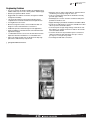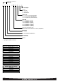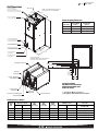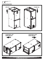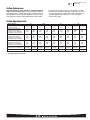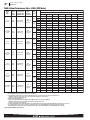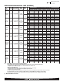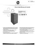
1
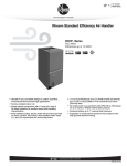
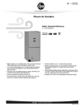
Air
Air Handlers
RHSL Series
Rheem Standard Efficiency Air Handler
RHSL- Series
PSC Motor
Efficiencies up to 15 SEER
• Versatile 4-way convertible design for upflow, downflow,
horizontal left and horizontal right applications.
• Factory-installed high efficiency indoor coil.
• Sturdy cabinet construction with 1.0 inch [25.4 mm] of
foil faced insulation for excellent sound and insulating
characteristics.
• Field-installed auxiliary electric heater kits provide exact heat
for indoor comfort. Kits include circuit breakers which meet
U.L. and cUL requirements for service disconnect.
• 11/2 ton [5.3 kW] through 5 ton [17.6 kW] models are between
421/2 to 551/2 inches [1080 to 1410 mm] tall and 22 inches
[559 mm] deep.
• All models meet or exceed 330 to 400 CFM [156 to 189 L/s] per
ton at .3 inches [.7 kPa] of external static pressure.
• Enhanced airflow up to .7" external static pressure.
FORM NO. H11-550
Air
Table of Contents
RHSL Series
TABLE OF CONTENTS
Engineering Features ......................................................................................3
Model Number Identification ............................................................................4
Dimensional Data............................................................................................5
Airflow Directional Data ..................................................................................6
Airflow Performance Data ..........................................................................7-11
Electrical Data ........................................................................................12-15
Electrical Wiring ............................................................................................16
Accessories ............................................................................................................16
Limited Warranty ..........................................................................................17
2
Air
Engineering Features
RHSL Series
Engineering Features
• The most compact unit design available, all standard heat air
handler models only 421/2 to 551/2 inches [1079 to 1409 mm] high.
• Attractive pre-painted cabinet exterior.
• Rugged wall steel cabinet construction, designed for added
strength and versatility.
• 1.0" foil faced insulation mechanically retained in blower
compartment for excellent thermal and sound performance.
• Four leg blower motor mount.
• Blower housing with controls, motor and blower. Slide out
design for service and maintenance convenience.
• Traditional open wire element design for heat applications.
• Field convertible for vertical downflow, horizontal left hand or
right hand air supply.
• 3 combustible floor base accessories fit all model sizes when
required for downflow installations on combustible floors.
• Indoor coil design provides low air side pressure drop, high
performance and extremely compact size.
• Expansion valve on indoor coil provides for operation with air
conditioning or heat pump using the same coil.
• Coils are constructed of aluminum fins bonded to internally
grooved copper tubing.
• Molded polymer corrosion resistant condensate drain pan is
provided on all indoor coils.
• Supply duct flanges provided as standard on air handler cabinet.
• Provisions for field electrical, connections available from either
side or top of the air handler cabinet.
• Connection point for high voltage wiring is inside the air handler cabinet. Low voltage connection is made on the outside
of the air handler cabinet.
• Concentric knockouts are provided for power connection to
cabinet. Installer may pull desired hole size up to 2 inches
[51 mm] for 11/2 inch [38 mm] conduit.
• Front refrigerant and drain connections.
[ ] Designates Metric Conversions
3
R
Air
Model Number Identification
RHSL Series
H
S
L
— HM 18 17
J
A
Design Variation
A = 1st Design
Voltage
A = 115/1/60
D = 480V-3-60
J = 208/240/1/60
Cabinet Size
17 = 17.5" [431.8 mm] (600-1200 CFM)
21 = 21" [533.4 mm] (1200-1600 CFM)
24 = 24.5" [609.6 mm] (1600-1800 CFM)
Capacity
18 = 18,000 BTU/H [5.27 kW]
24 = 24,000 BTU/H [7.03 kW]
30 = 30,000 BTU/H [8.79 kW]
36 = 36,000 BTU/H [10.55 kW]
42 = 42,000 BTU/H [12.31 kW]
48 = 48,000 BTU/H [14.06 kW]
60 = 60,000 BTU/H [17.58 kW]
HM = A/C or HP, Multi-Position
(Vertical Upflow/Horizontal Left is the factory configuration)
Refrigerant
L = R-410A
S = Standard Model (PSC Motor)
Classification
H = Air Handler
Rheem
[ ] Designates Metric Conversions
Available Models at 115V A Voltage
RHSL-HM1817AA
RHSL-HM2417AA
RHSL-HM3017AA
RHSL-HM3617AA
RHSL-HM4221AA
RHSL-HM4821AA
Available Models at 218V J Voltage
RHSL-HM1817JA
RHSL-HM2417JA
RHSL-HM3017JA
RHSL-HM3617JA
RHSL-HM3621JA
RHSL-HM4221JA
RHSL-HM4821JA
RHSL-HM4824JA
RHSL-HM6024JA*
Available Models at D Voltage
RHSL-HM3617DA
RHSL-HM4221DA
RHSL-HM4821DA
RHSL-HM4824DA
RHSL-HM6024DA
4
Air
Dimensional Data
RHSL Series
Unit Dimensions
SUPPLY AIR
ELECTRICAL CONNECTIONS
MAY EXIT TOP OR EITHER SIDE
HIGH VOLTAGE CONNECTION 7/8 [22.2 mm],
13/32 [27.8 mm], 131/32 [50 mm] DIA. KNOCKOUTS.
NOTE: 24 CLEARANCE REQUIRED IN FRONT OF
UNIT FOR FILTER AND COIL MAINTENANCE.
105/16
[262 mm]
W
A
LOW VOLTAGE CONNECTION
5/8 [15.9 mm] AND 7/8 [22.2 mm] KNOCKOUT
Return Air Opening Dimensions
Model
Cabinet Size
Return Air
Opening Width
(Inches)
Return Air Opening
Depth/Length
(Inches)
17
21
24
157/8
193/8
227/8
193/4
193/4
193/4
H
AUXILIARY DRAIN CONNECTION
3/4 [19.1 mm] FEMALE PIPE THREAD (NPT)
HORIZONTAL APPLICATION ONLY
PRIMARY DRAIN CONNECTION
3/4 [19.1 mm] FEMALE PIPE THREAD (NPT)
AUXILIARY DRAIN CONNECTION
3/4 [19.1 mm] FEMALE PIPE THREAD (NPT)
UPFLOW/DOWNFLOW APPLICATION ONLY
191/2 [495 mm]
RETURN AIR
OPENING
2111/16
[551 mm]
LIQUID LINE CONNECTION
COPPER (SWEAT)
VAPOR LINE CONNECTION
COPPER (SWEAT)
UPFLOW UNIT SHOWN:
UNIT MAY BE INSTALLED UPFLOW, DOWNFLOW,
HORIZONTAL RIGHT OR LEFT AIR SUPPLY.
515/16
[151 mm]
HORIZONTAL ADAPTER KIT
41/8
1
[105 mm] 3 /16
[76 mm] 13/16 [48 mm] 11/8 [29 mm]
11/16
[27 mm]
13/8
[35 mm]
213/16
[71 mm]
VAPOR LINE
CONNECTION
AUXILIARY HORIZONTAL
DRAIN CONNECTION
51/4
[133 mm]
53/8
[136 mm]
UPFLOW UNIT SHOWN:
UNIT MAY BE INSTALLED UPFLOW,
DOWNFLOW, HORIZONTAL RIGHT
OR LEFT AIR SUPPLY.
PRIMARY DRAIN
CONNECTION
LIQUID LINE
CONNECTION
[ ] Designates Metric Conversions
( ) Designates Unit with Double Coil Cabinet
VERTICAL DRAIN PAN
AUXILIARY UPFLOW/DOWNFLOW
DRAIN CONNECTION
Unit Dimensions & Weights
Model
Size
RHSL
Refrigerant Connections
Sweat (In.) [mm] ID
Liquid
Vapor
Unit
Width
“W” In. [mm]
Unit
Height
“H” In. [mm]
Supply
Duct
“A” In. [mm]
Air Flow
CFM (Nom.) [L/s]
Lo
Hi
Unit Weight/Shipping Weight
(Lbs.) [kg]
Unit With
Coil (Max. KW)
1817/2417
3/8
[9.53]
3/4
[19.05]
171/2 [445]
421/2 [1080]
161/2 [406]
600 [283]
800 [378]
82/96 [37/44]
3017/3617
3/8
[9.53]
3/4
[19.05]
171/2
421/2
[1080]
161/2 [406]
1000 [472]
1200 [566]
92/106 [37/48]
4221/4821
3/8
[9.53]
7/8
[22.23]
211/2 [533]
501/2 [1282]
191/2 [495]
1400 [661]
1600 [755]
150/166 [68/75]
4824
3/8
[9.53]
7/8
[22.23]
241/2 [622]
501/2 [1282]
231/2 [584]
1600 [755]
—
162/180 [73/81]
6024
3/8
[9.53]
7/8
[22.23]
241/2 [622]
551/2 [1410]
231/2 [584]
—
1800 [850]
181/198 [82/90]
[445]
*Maximum dehumidification airflow.
5
Air
Airflow Directional Data
RHSL Series
Airflow Directional Data
UPFLOW
HORIZONTAL LEFT
HAND AIRFLOW
6
DOWNFLOW
HORIZONTAL RIGHT
HAND AIRFLOW
Air
Airflow Performance Data
RHSL Series
Airflow Performance
Airflow performance data is based on cooling performance
with a coil and no filter in place. Select performance table for
appropriate unit size, voltage and number of electric heaters to
be used. Make sure external static applied to unit allows operation within the minimum and maximum limits shown in table
below for both cooling and electric heat operation. For optimum blower performance, operate the unit in the .3 [8 mm] to
.7 inches [18 mm] W.C. external static range. Units with coils
should be applied with a minimum of .1 inch [3 mm] W.C.
external static range.
Airflow Operating Limits
Model Cabinet Size
17
17/21
21
24
Cooling BTUH x 1,000
Cooling Tons Nominal
-018
1.5
-024
2
-030
2.5
-036
3
-038
3.5
-042
3.5
-048
4
-048
4
-060
5
Heat Pump or Air Conditioning
Maximum Heat/Cool CFM [L/s]
(37.5 CFM [18 L/s]/1,000 BTUH)
(450 CFM [212 L/s]/Ton Nominal)
675
[319]
900
[425]
1125
[531]
1350
[637]
1350
[637]
1575
[743]
1800
[850]
1800
[850]
1930
[911]
Heat Pump or Air Conditioning
Nominal Heat/Cool CFM [L/s]
(33.3 CFM [16 L/s]/1,000 BTUH)
(400 CFM [189 L/s]/Ton Nominal)
600
[283]
800
[378]
1000
[472]
1200
[566]
1200
[566]
1400
[661]
1600
[755]
1600
[755]
1800
[850]
Heat Pump or Air Conditioning
Minimum Heat/Cool CFM [L/s]
(30.0 CFM [14 L/s]/1,200 BTUH)
(360 CFM [170 L/s]/Ton Nominal)
540
[255]
720
[340]
900
[425]
1080
[510]
1080
[510]
1260
[595]
1440
[680]
1440
[680]
1620
[765]
Maximum kW Electric Heating
& Minimum Electric Heat CFM [L/s]
13
487 [230]
13
617 [291]
18
814 [384]
18
1054 [497]
18
1042 [492]
20
1171 [553]
25
1502 [709]
25
1502 [709]
30
1666 [786]
Maximum Electric Heat Rise °F [°C]
80 [26.7]
63 [17.2]
66 [18.9]
51 [10.6]
52 [11.1]
49 [9.4]
50 [10]
50 [10]
54 [12.2]
[ ] Designates Metric Conversions
7
Air
Airflow Performance Data
RHSL Series
240V Airflow Performance Data—RHSL (PSC Motor)
Model
No.
RHSL
Motor
Speed
from
Factory
Manufacturer
Recommended
Air-Flow Range
(Min/Max) CFM
Blower Size/
Motor
HP [W]
# of Speed
PSC CFM [L/s] Air Delivery/RPM/Watts—240 Volts
Motor
Speed
Low
-1817
No Heater
High
240V
517/711 CFM
[244/336 L/s]
10x6
1/5 HP [149]
2 Speed
High
Low
-1817
with 13 kW
Heater
High
240V
487/661 CFM
[230/312 L/s]
10x6
1/5 HP [149]
2 Speed
High
Low
-2417
No Heater
High
240V
647/888 CFM
[305/419 L/s]
10x6
1/5 HP [149]
2 Speed
High
Low
-2417
with 13 kW
Heater
High
240V
617/838 CFM
[291/395 L/s]
10x6
1/5 HP [149]
2 Speed
High
Low
-3017
No Heater
High
240V
864/1004 CFM
[408/474 L/s]
10x8
1/4 HP [186]
2 Speed
High
Low
-3017
with 18 kW
Heater
High
240V
814/904 CFM
[384/427 L/s]
10x8
1/4 HP [186]
2 Speed
High
Low
-3617/-3621
No Heater
High
240V
1104/1248 CFM
[521/589 L/s]
10x8
1/3 HP [249]
2 Speed
High
External Static Pressure—Inches W.C. [kPa]
0.1 [.02]
0.2 [.05]
0.3 [.07]
0.4 [.10]
0.5 [.12]
0.6 [.15]
0.7 [.17]
CFM
668 [315]
637 [301]
595 [281]
560 [264]
517 [244]
—
—
RPM
541
596
657
706
761
—
—
Watts
180
171
166
161
109
—
—
CFM
—
—
—
—
711 [336]
662 [312]
614 [290]
RPM
—
—
—
—
812
853
890
Watts
—
—
—
—
243
227
210
CFM
638 [301]
607 [286]
565 [267]
530 [250]
487 [230]
—
—
RPM
571
626
687
736
791
—
—
Watts
171
162
157
152
146
—
—
CFM
—
—
—
—
661 [312]
612 [289]
564 [266]
RPM
—
—
—
—
837
878
915
Watts
—
—
—
—
232
216
199
CFM
817 [386]
779 [368]
757 [357]
693 [327]
647 [305]
—
—
RPM
616
667
715
770
808
—
—
Watts
239
230
221
206
205
—
—
CFM
—
—
—
—
888 [419]
828 [391]
774 [365]
RPM
—
—
—
—
875
908
958
Watts
—
—
—
—
331
313
301
CFM
787 [371]
749 [353]
727 [343]
663 [313]
617 [291]
—
—
RPM
646
697
745
800
838
—
—
Watts
230
221
212
197
187
—
—
CFM
—
—
—
—
838 [395]
778 [367]
724 [342]
RPM
—
—
—
—
900
933
983
Watts
—
—
—
—
320
302
290
CFM
1022 [482]
987 [466]
940 [444]
903 [426]
864 [408]
—
—
RPM
700
754
794
633
870
—
—
Watts
344
313
302
309
288
—
—
CFM
—
—
—
—
1004 [474]
951 [449]
883 [417]
RPM
—
—
—
—
924
953
975
Watts
—
—
—
—
364
352
344
CFM
972 [459]
937 [442]
890 [420]
853 [403]
814 [384]
—
—
RPM
750
804
844
883
920
—
—
Watts
324
293
282
274
268
—
—
CFM
—
—
—
—
904 [427]
851 [402]
783 [370]
RPM
—
—
—
—
949
978
1000
Watts
—
—
—
—
334
322
314
CFM
1229 [580]
1201 [567]
1170 [552]
1141 [538]
1104 [521]
—
—
RPM
788
833
872
909
951
—
—
Watts
466
462
427
406
395
—
—
CFM
—
—
—
—
1248 [589]
1194 [563]
1133 [535]
RPM
—
—
—
—
1008
1028
1042
Watts
—
—
—
—
488
475
454
Notes: • All 208/240V PSC motors have voltage taps for 208 and 240 volts.
• All 208/240V PSC motors are shipped on high speed and 240 volts.
• If the application external static is less than 0.5" WC, adjust the motor speed to the low static speed as described below:
• Unplug the black motor wire off the relay on the control board and plug in the red motor wire.
• Replace the cap on the black motor wire.
• Voltage change (208/240V motors):
• Move the orange lead to transformer 208V tap from 240V tap. Replace the wire cap on 240V tap.
• Unplug the purple motor wire off the transformer and plug in the yellow motor wire.
• Replace the cap on the purple motor wire.
• The above airflow table lists the airflow information for air handlers without heater and air handler with maximum heater allowed for each model.
• The following formula can be used to calculate the approximate airflow, if a smaller (N kW) than the maximum heater kit is installed.
Approximate Airflow = Airflow without heater - (Airflow without heater - Airflow with maximum heater) x (N kW/maximum heater kW)
[ ] Designates Metric Conversions
8
Air
Airflow Performance Data
RHSL Series
240V Airflow Performance Data—RHSL (PSC Motor)
Model
No.
RHSL
Motor
Speed
from
Factory
Manufacturer
Recommended
Air-Flow Range
(Min/Max) CFM
Blower Size/
Motor
HP [W]
# of Speed
PSC CFM [L/s] Air Delivery/RPM/Watts—240 Volts
Motor
Speed
Low
-3617/3621
with 18 kW
Heater
High
240V
1054/1148 CFM
[497/542 L/s]
10x8
1/3 HP [249]
2 Speed
High
Low
-4221
No Heater
High
240V
1241/1537 CFM
[586/725 L/s]
10x10
1/2 HP [373]
2 Speed
High
Low
-4221
with 20 kW
Heater
High
240V
1225/1500 CFM
[553/678 L/s]
10x10
1/2 HP [373]
2 Speed
High
Low
-4821/-4824
No Heater
High
240V
1572/1824 CFM
[742/861 L/s]
10x10
3/4 HP [559]
2 Speed
High
Low
-4821/-4824
with 25 kW
Heater
High
240V
1225/1500 CFM
[709/814 L/s]
10x10
3/4 HP [559]
2 Speed
High
Low
-6024
No Heater
High
240V
1766/1965 CFM
[833/927 L/s]
11x11
3/4 HP [559]
2 Speed
High
Low
-6024
with 30 kW
Heater
High
240V
1225/1500 CFM
[709/814 L/s]
11x11
3/4 HP [559]
2 Speed
High
External Static Pressure—Inches W.C. [kPa]
0.1 [.02]
0.2 [.05]
0.3 [.07]
0.4 [.10]
0.5 [.12]
0.6 [.15]
0.7 [.17]
CFM
1179 [556]
1151 [543]
1120 [529]
1091 [515]
1054 [497]
—
—
RPM
838
883
922
959
1001
—
—
Watts
446
442
407
386
375
—
—
CFM
—
—
—
—
1148 [542]
1094 [516]
1033 [487]
RPM
—
—
—
—
1033
1053
1067
Watts
—
—
—
—
458
445
424
CFM
1526 [720]
1474 [696]
1427 [673]
1307 [617]
1241 [586]
—
—
RPM
834
870
902
948
968
—
—
Watts
560
549
535
476
462
—
—
CFM
—
—
—
—
1537 [725]
1418 [669]
1334 [630]
RPM
—
—
—
—
1072
1077
1085
Watts
—
—
—
—
860
835
820
CFM
1456 [687]
1404 [663]
1357 [640]
1237 [584]
1171 [553]
—
—
RPM
886
906
925
959
992
—
—
Watts
542
524
505
468
431
—
—
CFM
—
—
—
—
1437 [678]
1318 [622]
1234 [582]
RPM
—
—
—
—
1080
1090
1105
Watts
—
—
—
—
840
800
785
CFM
1741 [822]
1719 [811]
1667 [787]
1628 [768]
1572 [742]
—
—
RPM
878
920
950
981
1007
—
—
Watts
785
757
707
667
641
—
—
CFM
—
—
—
—
1824 [861]
1767 [834]
1653 [780]
RPM
—
—
—
—
1102
1112
1121
Watts
—
—
—
—
871
830
770
CFM
1671 [789]
1649 [778]
1597 [754]
1558 [735]
1502 [709]
—
—
RPM
945
965
995
1025
1050
—
—
Watts
715
685
650
630
610
—
—
CFM
—
—
—
—
1724 [814]
1667 [787]
1553 [733]
RPM
—
—
—
—
1116
1119
1130
Watts
—
—
—
—
810
780
730
CFM
1944 [917]
1912 [902]
1860 [878]
1813 [856]
1766 [833]
—
—
RPM
764
803
838
865
889
—
—
Watts
779
763
747
729
708
—
—
CFM
—
—
—
—
1965 [927]
1908 [900]
1854 [875]
RPM
—
—
—
—
943
967
977
Watts
—
—
—
—
828
799
795
CFM
1844 [870]
1812 [855]
1760 [831]
1713 [808]
1666 [786]
—
—
RPM
839
865
890
913
935
—
—
Watts
745
729
713
696
678
—
—
CFM
—
—
—
—
1865 [880]
1808 [853]
1754 [828]
RPM
—
—
—
—
987
1001
1014
Watts
—
—
—
—
788
766
744
Notes: • All 208/240V PSC motors have voltage taps for 208 and 240 volts.
• All 208/240V PSC motors are shipped on high speed and 240 volts.
• If the application external static is less than 0.5" WC, adjust the motor speed to the low static speed as described below:
• Unplug the black motor wire off the relay on the control board and plug in the red motor wire.
• Replace the cap on the black motor wire.
• Voltage change (208/240V motors):
• Move the orange lead to transformer 208V tap from 240V tap. Replace the wire cap on 240V tap.
• Unplug the purple motor wire off the transformer and plug in the yellow motor wire.
• Replace the cap on the purple motor wire.
• The above airflow table lists the airflow information for air handlers without heater and air handler with maximum heater allowed for each model.
• The following formula can be used to calculate the approximate airflow, if a smaller (N kW) than the maximum heater kit is installed.
Approximate Airflow = Airflow without heater - (Airflow without heater - Airflow with maximum heater) x (N kW/maximum heater kW)
[ ] Designates Metric Conversions
9
Air
Airflow Performance Data
RHSL Series
115V/208V/480V Airflow Performance Data—RHSL (PSC Motor)
Model
No.
RHSL
Motor
Speed
from
Factory
Manufacturer
Recommended
Air-Flow Range
(Min/Max) CFM
Blower Size/
Motor
HP [W]
# of Speed
PSC CFM [L/s] Air Delivery/RPM/Watts—115/208/480 Volts
Motor
Speed
Low
-1817
No Heater
High
523/705 CFM
[247/333 L/s]
10x6
1/5 HP [149]
2 Speed
High
Low
-1817
with 13 kW
Heater
High
487/661 CFM
[230/312 L/s]
10x6
1/5 HP [149]
2 Speed
High
Low
-2417
No Heater
High
647/888 CFM
[305/419 L/s]
10x6
1/5 HP [149]
2 Speed
High
Low
-2417
with 13 kW
Heater
High
617/838 CFM
[291/395 L/s]
10x6
1/5 HP [149]
2 Speed
High
Low
-3017
No Heater
High
864/1004 CFM
[408/474 L/s]
10x8
1/4 HP [186]
2 Speed
High
Low
-3017
with 18 kW
Heater
High
814/904 CFM
[384/427 L/s]
10x8
1/4 HP [186]
2 Speed
High
Low
-3617/-3621
No Heater
High
1104/1248 CFM
[521/589 L/s]
10x8
1/3 HP [249]
2 Speed
High
External Static Pressure—Inches W.C. [kPa]
0.1 [.02]
0.2 [.05]
0.3 [.07]
0.4 [.10]
0.5 [.12]
0.6 [.15]
0.7 [.17]
CFM
681 [321]
636 [300]
606 [286]
567 [268]
523 [247]
—
—
RPM
541
601
670
714
768
—
—
Watts
193
181
173
164
157
—
—
CFM
—
—
—
—
705 [333]
650 [307]
599 [283]
RPM
—
—
—
—
815
861
989
Watts
—
—
—
—
239
227
204
CFM
651 [307]
606 [286]
576 [272]
537 [253]
493 [233]
—
—
RPM
571
631
700
744
798
—
—
Watts
184
172
164
155
148
—
—
CFM
—
—
—
—
655 [309]
600 [283]
549 [259]
RPM
—
—
—
—
840
886
1014
Watts
—
—
—
—
228
216
193
CFM
875 [413]
806 [380]
787 [371]
739 [349]
682 [322]
—
—
RPM
648
700
745
794
827
—
—
Watts
259
255
243
234
227
—
—
CFM
—
—
—
—
897 [423]
851 [402]
765 [361]
RPM
—
—
—
—
906
925
955
Watts
—
—
—
—
332
318
306
CFM
845 [399]
776 [366]
757 [357]
709 [335]
652 [308]
—
—
RPM
678
730
775
824
857
—
—
Watts
250
246
234
225
218
—
—
CFM
—
—
—
—
847 [400]
801 [378]
715 [337]
RPM
—
—
—
—
931
950
980
Watts
—
—
—
—
321
307
295
CFM
1038 [490]
1010 [477]
976 [461]
925 [437]
883 [417]
—
—
RPM
721
771
799
848
880
—
—
Watts
325
314
303
290
286
—
—
CFM
—
—
—
—
1015 [479]
963 [454]
890 [420]
RPM
—
—
—
—
928
955
974
Watts
—
—
—
—
356
341
329
CFM
988 [466]
960 [453]
926 [437]
875 [413]
833 [393]
—
—
RPM
771
821
849
898
930
—
—
Watts
305
294
283
270
266
—
—
CFM
—
—
—
—
915 [432]
863 [407]
790 [373]
RPM
—
—
—
—
953
980
999
Watts
—
—
—
—
326
311
299
CFM
1201 [567]
1170 [552]
1141 [538]
1104 [521]
1062 [501]
—
—
RPM
833
872
909
951
965
—
—
Watts
462
427
406
396
385
—
—
CFM
—
—
—
—
1194 [563]
1134 [535]
1078 [509]
RPM
—
—
—
—
1024
1042
1060
Watts
—
—
—
—
475
454
417
Notes: • All 208/240V PSC motors have voltage taps for 208 and 240 volts.
• All 208/240V PSC motors are shipped on high speed and 240 volts.
• All 115V PSC motors are shipped on high speed.
• If the application external static is less than 0.5" WC, adjust the motor speed to
the low static speed as described below:
• Unplug the black motor wire off the relay on the control board and
plug in the red motor wire.
• Replace the cap on the black motor wire.
• Voltage change (208/240V motors):
• Move the orange lead to transformer 208V tap from 240V tap.
Replace the wire cap on 240V tap.
• Unplug the purple motor wire off the transformer and plug in the
yellow motor wire.
• Replace the cap on the purple motor wire.
• All 480V PSC motors are shipped on high speed.
• If the application external static is less than 0.5" WC, adjust the motor speed to
the low static speed as described below for 3-ton through 4-ton air handlers.
10
• Unplug the black motor wire off the relay and remove the cap from
the red motor wire.
• Plug the red motor wire to the relay and connect the black motor
wire with the yellow motor wire.
• For 5-ton air handler, unplug the black motor wire off the relay and plug in the red
motor wire, then cap the black motor wire. There is no yellow motor wire on 5-ton
air handler.
WARNING: Do not connect red motor wire with yellow motor wire in any circumstance on
480V PSC motors. Connecting red motor wire with yellow motor wire will result in
permanent motor damage.
• The above airflow table lists the airflow information for air handlers without heater and air
handler with maximum heater allowed for each model.
• The following formula can be used to calculate the approximate airflow, if a smaller (N kW)
than the maximum heater kit is installed. Approximate Airflow = Airflow without heater (Airflow without heater - Airflow with maximum heater) x (N kW/maximum heater kW)
[ ] Designates Metric Conversions
Air
Airflow Performance Data
RHSL Series
115V/208V/480V Airflow Performance Data—RHSL (PSC Motor)
Model
No.
RHSL
Motor
Speed
from
Factory
Manufacturer
Recommended
Air-Flow Range
(Min/Max) CFM
Blower Size/
Motor
HP [W]
# of Speed
PSC CFM [L/s] Air Delivery/RPM/Watts—115/208/480V Volts
Motor
Speed
Low
-3617/3621
with 18 kW
Heater
High
1054/1148 CFM
[497/542 L/s]
10x8
1/3 HP [249]
2 Speed
High
Low
-4221
No Heater
High
1241/1537 CFM
[580/725 L/s]
10x10
1/2 HP [373]
2 Speed
High
Low
-4221
with 20 kW
Heater
High
1225/1500 CFM
[538/667 L/s]
10x10
1/2 HP [373]
2 Speed
High
Low
-4821/-4824
No Heater
High
1512/1824 CFM
[742/801 L/s]
10x10
3/4 HP [559]
2 Speed
High
Low
-4821/-4824
with 25 kW
Heater
High
1225/1500 CFM
[695/796 L/s]
10x10
3/4 HP [559]
2 Speed
High
Low
-6024
No Heater
High
1766/1965 CFM
[833/927 L/s]
11x11
3/4 HP [559]
2 Speed
High
Low
-6024
with 30 kW
Heater
High
1225/1500 CFM
[695/796 L/s]
11x11
3/4 HP [559]
2 Speed
High
External Static Pressure—Inches W.C. [kPa]
0.1 [.02]
0.2 [.05]
0.3 [.07]
0.4 [.10]
0.5 [.12]
0.6 [.15]
0.7 [.17]
CFM
1151 [543]
1120 [529]
1091 [515]
1054 [497]
1012 [478]
—
—
RPM
883
922
959
1001
1015
—
—
Watts
442
407
386
376
365
—
—
CFM
—
—
—
—
1094 [516]
1034 [488]
978 [462]
RPM
—
—
—
—
1049
1067
1085
Watts
—
—
—
—
445
424
387
CFM
1493 [705]
1449 [684]
1363 [643]
1287 [607]
1211 [571]
—
—
RPM
822
858
885
931
958
—
—
Watts
540
519
506
484
459
—
—
CFM
—
—
—
—
1514 [714]
1411 [666]
1315 [621]
RPM
—
—
—
—
1061
1069
1078
Watts
—
—
—
—
710
702
677
CFM
1423 [672]
1379 [651]
1293 [610]
1217 [574]
1141 [538]
—
—
RPM
870
882
925
957
992
—
—
Watts
514
508
490
461
431
—
—
CFM
—
—
—
—
1414 [667]
1311 [619]
1215 [573]
RPM
—
—
—
—
1067
1080
1094
Watts
—
—
—
—
700
678
665
CFM
1711 [807]
1689 [797]
1637 [773]
1598 [754]
1542 [728]
—
—
RPM
863
905
935
966
992
—
—
Watts
765
737
687
647
621
—
—
CFM
—
—
—
—
1787 [843]
1679 [792]
1575 [743]
RPM
—
—
—
—
1089
1098
1110
Watts
—
—
—
—
695
665
630
CFM
1641 [774]
1619 [764]
1567 [739]
1528 [721]
1472 [695]
—
—
RPM
930
950
985
1015
1041
—
—
Watts
700
660
630
600
580
—
—
CFM
—
—
—
—
1687 [796]
1579 [745]
1475 [696]
RPM
—
—
—
—
1095
1107
1120
Watts
—
—
—
—
670
635
615
CFM
1866 [881]
1833 [865]
1806 [852]
1772 [836]
1710 [807]
—
—
RPM
764
803
824
856
886
—
—
Watts
778
756
733
715
701
—
—
CFM
—
—
—
—
1967 [928]
1916 [904]
1863 [879]
RPM
—
—
—
—
948
959
991
Watts
—
—
—
—
850
827
816
CFM
1796 [848]
1763 [832]
1736 [819]
1702 [803]
1640 [774]
—
—
RPM
828
860
878
890
1001
—
—
Watts
735
718
705
695
678
—
—
CFM
—
—
—
—
1867 [881]
1816 [857]
1763 [832]
RPM
—
—
—
—
989
1005
1020
Watts
—
—
—
—
818
795
780
Notes: • All 208/240V PSC motors have voltage taps for 208 and 240 volts.
• All 208/240V PSC motors are shipped on high speed and 240 volts.
• All 115V PSC motors are shipped on high speed.
• If the application external static is less than 0.5" WC, adjust the motor speed to
the low static speed as described below:
• Unplug the black motor wire off the relay on the control board and
plug in the red motor wire.
• Replace the cap on the black motor wire.
• Voltage change (208/240V motors):
• Move the orange lead to transformer 208V tap from 240V tap.
Replace the wire cap on 240V tap.
• Unplug the purple motor wire off the transformer and plug in the
yellow motor wire.
• Replace the cap on the purple motor wire.
• All 480V PSC motors are shipped on high speed.
• If the application external static is less than 0.5" WC, adjust the motor speed to
the low static speed as described below for 3-ton through 4-ton air handlers.
• Unplug the black motor wire off the relay and remove the cap from
the red motor wire.
• Plug the red motor wire to the relay and connect the black motor
wire with the yellow motor wire.
• For 5-ton air handler, unplug the black motor wire off the relay and plug in the red
motor wire, then cap the black motor wire. There is no yellow motor wire on 5-ton
air handler.
WARNING: Do not connect red motor wire with yellow motor wire in any circumstance on
480V PSC motors. Connecting red motor wire with yellow motor wire will result in
permanent motor damage.
• The above airflow table lists the airflow information for air handlers without heater and air
handler with maximum heater allowed for each model.
• The following formula can be used to calculate the approximate airflow, if a smaller (N kW)
than the maximum heater kit is installed. Approximate Airflow = Airflow without heater (Airflow without heater - Airflow with maximum heater) x (N kW/maximum heater kW)
[ ] Designates Metric Conversions
11
Air
Electrical Data
RHSL Series
Electrical Data – Blower Motor Only – No Electric Heat
Model
RHLL
1817
2417
3017
3617
4221
4821
1817
2417
3017
3617/5621
4221
4821/4824
6024
3617
4221
4821/4824
6024
Voltage
Application
Phase*
115
1
60
208/240
1&3
60
208/240
3
60
480
3
60
480
3
60
* Blower motors are all single phase motors.
[ ] Designates Metric Conversions
12
Hertz
HP [W]
RPM
Speeds
Circuit
Amps.
1/5 [149]
1/5 [149]
1/4 [186]
1/3 [249]
1/2 [373]
3/4 [559]
1/5 [149]
1/5 [149]
1/4 [186]
1/3 [249]
1/2 [373]
3/4 [559]
3/4 [559]
1/3 [249]
1/3 [249]
3/4 [559]
3/4 [559]
1075
1075
1075
1075
1075
1075
1075
1075
1075
1075
1075
1075
1075
1075
1075
1075
1075
2
2
2
2
2
2
2
2
2
2
2
2
2
2
2
2
2
2.3
3.8
4.7
6.1
7.9
8.4
1.7
1.7
2.5
2.5
5.2
5.2
5.2
1.4
2.1
2.2
2.2
Minimum
Circuit
Ampacity
3.0
5.0
6.0
8.0
10.0
11.0
3.0
3.0
4.0
4.0
7.0
7.0
7.0
2.0
3.0
3.0
3.0
Maximum
Circuit
Protector
15
15
15
15
15
15
15
15
15
15
15
15
15
15
15
15
15
Air
Electrical Data
RHSL Series
Electrical Data – With Electric Heat
Installation of the U.L. Listed original equipment manufacturer provided heater kits listed in the following table is recommended for all
auxiliary heating requirements.
Air Handler
Model
RHSL
1817/2417
Heater Model No.
No. Elements
kW Per
Type Supply
Circuit Single
Circuit Multiple
Circuit
Amps.
Motor
Ampacity
Minimum
Circuit
Ampacity
Maximum
Circuit
Protection
RXBH-1724?03J
2.25/3.0
1/60
1 - 3.0
SINGLE
10.8/12.5
1.7
16/18
20/20
3.6/4.8
1/60
1 - 4.8
SINGLE
17.3/20.0
1.7
24/28
25/30
RXBH-1724?07J
5.4/7.2
1/60
2 - 3.6
SINGLE
26.0/30.0
1.7
35/40
35/40
RXBH-1724?10J
7.2/9.6
1/60
2 - 4.8
SINGLE
34.6/40.0
1.7
46/53
50/60
RXBH-1724A13J
9.4/12.5
1/60
3-4.17
SINGLE
45.1/52.1
1.7
59/68
60/70
3.1/4.2
1/60
1-4.17
MULTIPLE CKT 1
15./17.4
1.7
21/24
25/25
6.3/8.3
1/60
2-4.17
MULTIPLE CKT 2
30.1/34.7
0.0
38/44
40/45
RXBH-1724A07C
5.4/7.2
3/60
3 - 2.4
SINGLE
15.0/17.3
1.7
21/24
25/25
RXBH-1724A10C
7.2/9.6
3/60
3 - 3.2
SINGLE
20.0/23.1
1.7
28/31
30/35
RXBH-1724A13C
9.4/12.5
3/60
3-4.17
SINGLE
26.1/30.1
1.7
35/40
35/40
RXBH-1724?03J
2.25/3.0
1/60
1 - 3.0
SINGLE
10.8/12.5
2.5
17/19
20/20
RXBH-1724?05J
3.6/4.8
1/60
1 - 4.8
SINGLE
17.3/20.0
2.5
25/29
25/30
RXBH-1724?07J
5.4/7.2
1/60
2 - 3.6
SINGLE
26.0/30.0
2.5
36/41
40/45
RXBH-1724?10J
7.2/9.6
1/60
2 - 4.8
SINGLE
34.6/40.0
2.5
47/54
50/60
RXBH-1724A13J
9.4/12.5
1/60
3-4.17
SINGLE
45.1/52.1
2.5
60/69
602/70
3.1/4.2
1/60
1-4.17
MULTIPLE CKT 1
15.0/17.4
2.5
22/25
25/25
6.3/8.3
1/60
2-4.17
MULTIPLE CKT 2
30.1/34.7
0.0
38/44
40/45
10.8/14.4
1/60
3-4.8
SINGLE
51.9/60.0
2.5
68/79
70/80
3.6/4.8
1/60
1 - 4.8
MULTIPLE CKT 1
17.3/20.0
2.5
25/29
25/30
7.2/9.6
1/60
2 - 4.8
MULTIPLE CKT 2
34.6/40.0
0.0
44/50
45/50
12.8/17
1/60
3-5.68
SINGLE
61.6/70.8
2.5
81/92
90/100
4.3/5.7
1/60
1 - 5.68
MULTIPLE CKT 1
20.5/23.6
2.5
29/33
30/35
8.7/11.3
1/60
2 - 5.86
MULTIPLE CKT 2
41.1/47.2
0.0
52/59
60/60
RXBH-1724A07C
5.4/7.2
3/60
3 - 2.4
SINGLE
15.0/17.3
2.5
22/25
25/25
RXBH-1724A10C
7.2/9.6
3/60
3 - 3.2
SINGLE
20.0/23.1
2.5
29/32
30/35
RXBH-1724A13C
9.4/12.5
3/60
3-4.17
SINGLE
26.1/30.1
2.5
36/41
40/45
RXBH-1724A13J
RXBH-1724A15J
RXBH-1724A15J
RXBH-1724A18J
RXBH-1724A18J
3621
PH/HZ
RXBH-1724?05J
RXBH-1724A13J
3017/3617
Heater kW
(208/240V)
(480V)
RXBH-1724A15C
10.8/14.4
3/60
3 - 4.8
SINGLE
30.0/34.6
2.5
41/47
45/50
RXBH-1724A18C
12.8/17.0
3/60
3-5.68
SINGLE
35.5/41.0
2.5
48.55
50/60
RXBH-17A07D
7.2
3/60
2-3.6
SINGLE
8.7
1.4
13
15
RXBH-17A10D
9.6
3/60
3-3.2
SINGLE
11.6
1.4
17
20
RXBH-17A15D
14.4
3/60
3-4.8
SINGLE
17.3
1.4
24
25
RXBH-17A18D
17
3/60
3-5.68
SINGLE
20.4
1.4
28
30
RXBH-1724?05J
3.6/4.8
1/60
1 - 4.8
SINGLE
17.3/20.0
2.5
25/29
25/30
RXBH-1724?07J
5.4/7.2
1/60
2 - 3.6
SINGLE
26.0/30.0
2.5
36/41
40/45
RXBH-1724?10J
7.2/9.6
1/60
2 - 4.8
SINGLE
34.6/40.0
2.5
47/54
50/60
RXBH-1724A13J
9.4/12.5
1/60
3-4.17
SINGLE
45.1/52.1
2.5
60/69
602/70
3.1/4.2
1/60
1-4.17
MULTIPLE CKT 1
15.0/17.4
2.5
22/25
25/25
6.3/8.3
1/60
2-4.17
MULTIPLE CKT 2
30.1/34.7
0.0
38/44
40/45
10.8/14.4
1/60
3-4.8
SINGLE
51.9/60.0
2.5
68/79
70/80
3.6/4.8
1/60
1 - 4.8
MULTIPLE CKT 1
17.3/20.0
2.5
25/29
25/30
7.2/9.6
1/60
2 - 4.8
MULTIPLE CKT 2
34.6/40.0
0.0
44/50
45/50
12.8/17
1/60
3-5.68
SINGLE
61.6/70.8
2.5
81/92
90/100
RXBH-1724A13J
RXBH-1724A15J
RXBH-1724A15J
RXBH-1724A18J
• Supply circuit protective devices may be fuses or “HACR” type circuit breakers.
• Largest motor load is included in single circuit and multiple circuit 1.
• If non-standard fuse size is specified, use next size larger standard fuse size.
• J Voltage (230V) single phase air handler is designed to be used with single or three phase 230 volt electric heaters. In the case of connecting 3-phase power to the air handler terminal block
without the heater, bring only two leads to the terminal block cap, insulate and fully secure the third lead.
[ ] Designates Metric Conversions
13
Air
Electrical Data
RHSL Series
Electrical Data – With Electric Heat (Cont.)
Installation of the U.L. Listed original equipment manufacturer provided heater kits listed in the following table is recommended for all
auxiliary heating requirements.
Air Handler
Model
RHSL
Heater Model No.
RXBH-1724A18J
RXBH-1724A07C
3621
Heater kW
(208/240V)
(480V)
PH/HZ
No. Elements
kW Per
Type Supply
Circuit Single
Circuit Multiple
Circuit
Amps.
Motor
Ampacity
Minimum
Circuit
Ampacity
Maximum
Circuit
Protection
4.3/5.7
1/60
1 - 5.68
MULTIPLE CKT 1
20.5/23.6
2.5
29/33
30/35
8.7/11.3
1/60
2 - 5.86
MULTIPLE CKT 2
41.1/47.2
0.0
52/59
60/60
5.4/7.2
3/60
3 - 2.4
SINGLE
15.0/17.3
2.5
22/25
25/25
RXBH-1724A10C
7.2/9.6
3/60
3 - 3.2
SINGLE
20.0/23.1
2.5
29/32
30/35
RXBH-1724A13C
9.4/12.5
3/60
3-4.17
SINGLE
26.1/30.1
2.5
36/41
40/45
RXBH-1724A15C
10.8/14.4
3/60
3 - 4.8
SINGLE
30.0/34.6
2.5
41/47
45/50
RXBH-1724A18C
12.8/17.0
3/60
3-5.68
SINGLE
35.5/41.0
2.5
48.55
50/60
RXBH-17A07D
7.2
3/60
2-3.6
SINGLE
8.7
1.4
13
15
RXBH-17A10D
9.6
3/60
3-3.2
SINGLE
11.6
1.4
17
20
RXBH-17A15D
14.4
3/60
3-4.8
SINGLE
17.3
1.4
24
25
RXBH-17A18D
17
3/60
3-5.68
SINGLE
20.4
1.4
28
30
RXBH-1724?05J
3.6/4.8
1/60
1 - 4.8
SINGLE
17.3/20.0
5.2
29/32
30/35
RXBH-1724?07J
5.4/7.2
1/60
2 - 3.6
SINGLE
26.0/30.0
5.2
39/44
40/45
RXBH-1724?10J
7.2/9.6
1/60
2 - 4.8
SINGLE
34.6/40.0
5.2
50/57
50/60
RXBH-1724A15J
10.8/14.4
1/60
3-4.8
SINGLE
51.9/60.0
5.2
72/82
80/90
3.6/4.8
1/60
1 - 4.8
MULTIPLE CKT 1
17.3/20.0
5.2
29/32
30/35
7.2/9.6
1/60
2 - 4.8
MULTIPLE CKT 2
34.6/40.0
0.0
44/50
45/50
12.8/17
1/60
3-5.68
SINGLE
61.6/70.8
5.2
84/95
90/100
RXBH-1724A15J
RXBH-1724A18J
RXBH-1724A18J
RXBH-24A20J
RXBH-24A20J
RXBH-24A25J (4-ton only)
RXBH-24A25J
4221/4821
4824
RXBH-1724A07C
4.3/5.7
1/60
1 - 5.68
MULTIPLE CKT 1
20.5/23.6
5.2
33/36
35/40
8.7/11.3
1/60
2 - 5.86
MULTIPLE CKT 2
41.1/47.2
0.0
52/59
60/60
14.4/19.2
1/60
4-4.8
SINGLE
69.2/80
5.2
93/107
100/110
7.2/9.6
1/60
2 - 4.8
MULTIPLE CKT 1
34.6/40.0
5.2
50/57
50/60
7.2/9.6
1/60
2 - 4.8
MULTIPLE CKT 2
34.6/40.0
0.0
44/50
45/50
18.0/24.0
1/60
6-4.0
SINGLE
86.4/99.9
5.2
115/132
125/150
6.0/8.0
1/60
2-4.0
MULTIPLE CKT 1
28.8/33.3
5.2
43/49
45/50
6.0/8.0
1/60
2-4.0
MULTIPLE CKT 2
28.8/33.3
0.0
36/42
40/45
6.0/8.0
1/60
2-4.0
MULTPLE CKT 3
28.8/33.3
0.0
36/42
40/45
5.4/7.2
3/60
3 - 2.4
SINGLE
15.0/17.3
5.2
26/29
30/30
35/40
RXBH-1724A10C
7.2/9.6
3/60
3 - 3.2
SINGLE
20.0/23.1
5.2
32/36
RXBH-1724A15C
10.8/14.4
3/60
3 - 4.8
SINGLE
30.0/34.6
5.2
44/50
45/50
RXBH-1724A18C
12.8/17.0
3/60
3-2.84
SINGLE
35.6/41.0
5.2
51/58
60/60
RXBH-1724A18C
RXBH-24A20C
RXBH-24A20C
4.3/5.7
3/60
3 - 2.84
MULTIPLE CKT 1
17.8/20.5
5.2
29/33
30/35
8.7/11.3
3/60
3 - 2.84
MULTIPLE CKT 2
17.8/20.5
0.0
23/26
25/30
7.2-9.6
3/60
3-3.2
SINGLE
40.0/46.2
5.2
57/65
60/70
7.2/9.6
3/60
3 - 3.2
MULTIPLE CKT 1
20.0/23.1
5.2
32/36
35/40
7.2/9.6
3/60
3 - 3.2
MULTIPLE CKT 2
20.0/23.1
0.0
25/29
25/30
18.0/24.0
3/60
6-4.0
SINGLE
50.0/57.8
5.2
69/79
70/80
9.0/12.0
3/60
3-4.0
MULTIPLE CKT 1
25.0/28.9
5.2
38/43
40/45
9.0/12.0
3/60
3-4.0
MULTIPLE CKT 2
25.0/28.9
0.0
32/37
35/40
RXBH-24A07D
7.2
3/60
2-3.6
SINGLE
8.7
2.2
14
15
RXBH-24A10D
9.6
3/60
3-3.2
SINGLE
11.6
2.2
18
20
RXBH-24A15D
14.4
3/60
3-4.8
SINGLE
17.3
2.2
25
25
RXBH-24A25C (4-ton only)
RXBH-24A25C (4-ton only)
• Supply circuit protective devices may be fuses or “HACR” type circuit breakers.
• Largest motor load is included in single circuit and multiple circuit 1.
• If non-standard fuse size is specified, use next size larger standard fuse size.
• J Voltage (230V) single phase air handler is designed to be used with single or three phase 230 volt electric heaters. In the case of connecting 3-phase power to the air handler terminal block
without the heater, bring only two leads to the terminal block cap, insulate and fully secure the third lead.
[ ] Designates Metric Conversions
14
Air
Electrical Data
RHSL Series
Electrical Data – With Electric Heat (Cont.)
Installation of the U.L. Listed original equipment manufacturer provided heater kits listed in the following table is recommended for all
auxiliary heating requirements.
Air Handler
Model
RHSL
4221/4821/
4824
Heater Model No.
Heater kW
(208/240V)
(480V)
PH/HZ
No. Elements
kW Per
Type Supply
Circuit Single
Circuit Multiple
Circuit
Amps.
Motor
Ampacity
Minimum
Circuit
Ampacity
Maximum
Circuit
Protection
RXBH-24A18D
17.0
3/60
3-5.68
SINGLE
20.4
2.2
29
30
RXBH-24A20D
19.2
3/60
6-3.2
SINGLE
23.2
2.2
32
35
RXBH-24A25D (4-ton only)
24.0
3/60
6-4.0
SINGLE
28.8
2.2
39
40
RXBH-1724?05J
3.6/4.8
1/60
1 - 4.8
SINGLE
17.3/20.0
5.2
29/32
30/35
RXBH-1724?07J
5.4/7.2
1/60
2 - 3.6
SINGLE
26.0/30.0
5.2
39/44
40/45
RXBH-1724?10J
7.2/9.6
1/60
2 - 4.8
SINGLE
34.6/40.0
5.2
50/57
50/60
RXBH-1724A15J
10.8/14.4
1/60
3-4.8
SINGLE
51.9/60.0
5.2
72/82
80/90
3.6/4.8
1/60
1 - 4.8
MULTIPLE CKT 1
17.3/20.0
5.2
29/32
30/35
7.2/9.6
1/60
2 - 4.8
MULTIPLE CKT 2
34.6/40.0
0.0
44/50
45/50
12.8/17
1/60
3-5.68
SINGLE
61.6/70.8
5.2
84/95
90/100
4.3/5.7
1/60
1 - 5.68
MULTIPLE CKT 1
20.5/23.6
5.2
33/36
35/40
8.7/11.3
1/60
2 - 5.86
MULTIPLE CKT 2
41.1/47.2
0.0
52/59
60/60
14.4/19.2
1/60
4-4.8
SINGLE
69.2/80
5.2
93/107
100/110
50/60
RXBH-1724A15J
RXBH-1724A18J
RXBH-1724A18J
RXBH-24A20J
RXBH-24A20J
RXBH-24A25J
RXBH-24A25J
RXBH-24A30J
7.2/9.6
1/60
2 - 4.8
MULTIPLE CKT 1
34.6/40.0
5.2
50/57
7.2/9.6
1/60
2 - 4.8
MULTIPLE CKT 2
34.6/40.0
0.0
44/50
45/50
18.0/24.0
1/60
6-4.0
SINGLE
86.4/99.9
5.2
115/132
125/150
6.0/8.0
1/60
2-4.0
MULTIPLE CKT 1
28.8/33.3
5.2
43/49
45/50
6.0/8.0
1/60
2-4.0
MULTIPLE CKT 2
28.8/33.3
0.0
36/42
40/45
6.0/8.0
1/60
2-4.0
MULTPLE CKT 3
28.8/33.3
0.0
36/42
40/45
21.6/28.8
1/60
6-4.8
SINGLE
103.8/120
5.2
137/157
150/175
7.2/9.6
1/60
2-4.8
MULTIPLE CKT 1
34.6/40.0
5.2
50/57
50/6
RXBH-24A30J
7.2/9.6
1/60
2-4.8
MULTIPLE CKT 2
34.6/40.0
0.0
44/50
45/50
7.2/9.6
1/60
2-4.8
MULTPLE CKT 3
34.6/40.0
0.0
44/50
45/50
RXBH-1724A07C
5.4/7.2
3/60
3 - 2.4
SINGLE
15.0/17.3
5.2
26/29
30/30
RXBH-1724A10C
7.2/9.6
3/60
3 - 3.2
SINGLE
20.0/23.1
5.2
32/36
35/40
RXBH-1724A15C
10.8/14.4
3/60
3 - 4.8
SINGLE
30.0/34.6
5.2
44/50
45/50
RXBH-1724A18C
12.8/17.0
3/60
3-2.84
SINGLE
35.6/41.0
5.2
51/58
60/60
6.4/8.5
3/60
3 - 2.84
MULTIPLE CKT 1
17.8/20.5
5.2
29/33
30/35
25/30
6024
RXBH-1724A18C
RXBH-24A20C
RXBH-24A20C
6.4/8.5
3/60
3 - 2.84
MULTIPLE CKT 2
17.8/20.5
0.0
23/26
7.2-9.6
3/60
3-3.2
SINGLE
40.0/46.2
5.2
57/65
60/70
7.2/9.6
3/60
3 - 3.2
MULTIPLE CKT 1
20.0/23.1
5.2
32/36
35/40
7.2/9.6
3/60
3 - 3.2
MULTIPLE CKT 2
20.0/23.1
0.0
25/29
25/30
18.0/24.0
3/60
6-4.0
SINGLE
50.0/57.8
5.2
69/79
70/80
9.0/12.0
3/60
3-4.0
MULTIPLE CKT 1
25.0/28.9
5.2
38/43
40/45
9.0/12.0
3/60
3-4.0
MULTIPLE CKT 2
25.0/28.9
0.0
32/37
35/40
RXBH-24A07D
7.2
3/60
2-3.6
SINGLE
8.7
2.2
14
15
RXBH-24A10D
9.6
3/60
3-3.2
SINGLE
11.6
2.2
18
20
RXBH-24A15D
14.4
3/60
3-4.8
SINGLE
17.3
2.2
25
25
RXBH-24A18D
17.0
3/60
3-5.68
SINGLE
20.4
2.2
29
30
RXBH-24A20D
19.2
3/60
6-3.2
SINGLE
23.2
2.2
32
35
RXBH-24A25D
24.0
3/60
6-4.0
SINGLE
28.8
2.2
39
40
RXBH-24A30D
28.8
3/60
6-4.8
SINGLE
34.6
2.2
46
50
RXBH-24A25C
RXBH-24A25C
• Supply circuit protective devices may be fuses or “HACR” type circuit breakers.
• Largest motor load is included in single circuit and multiple circuit 1.
• If non-standard fuse size is specified, use next size larger standard fuse size.
• J Voltage (230V) single phase air handler is designed to be used with single or three phase 230 volt electric heaters. In the case of connecting 3-phase power to the air handler terminal block
without the heater, bring only two leads to the terminal block cap, insulate and fully secure the third lead.
[ ] Designates Metric Conversions
15
Electrical Wiring
RHSL Series
Air
Electrical Wiring
Power Wiring
Grounding
• Field wiring must comply with the National Electrical Code
(C.E.C. in Canada) and any applicable local ordinance.
• This product must be sufficiently grounded in accordance with
National Electrical Code (C.E.C. in Canada) and any applicable
local ordinance.
• Supply wiring must be 75°C minimum copper conductors only.
• See electrical data for product Ampacity rating and Circuit
Protector requirement.
• A grounding lug is provided.
Accessories
• Combustible Floor Base RXHB-
• Auxiliary Electric Heater Kits RXBHHeater Kits include circuit breakers which meet UL and cUL
requirements for service disconnect. See the Electric Heat
Electrical Data in this specification sheet for specific Heater Kit
Model numbers.
Combustible Floor
Base Model Number
RXHB-17
RXHB-21
RXHB-24
Model Cabinet Size
17
21
24
• Jumper Bar Kit 3 Ckt. to 1 Ckt. RXBJ-A31 is used to convert
single phase multiple three circuit units to a single supply
circuit. Kit includes cover and screw for line side terminals.
• Jumper Bar Kit 2 Ckt. to 1 Ckt. RXBJ-A21 is used to convert
single phase multiple two circuit units to a single supply circuit.
Kit includes cover and screw for line side terminals.
• Note: No jumper bar kit is available to convert three phase
multiple two circuit units to a single supply circuit.
• Auxiliary Horizontal Overflow Pan Accessory RXBMNominal Cooling
Capacity-Tons
11/2 - 3
31/2 - 5
Auxiliary Horizontal Overflow Pan
Accessory Model Number
RXBM-AC48
RXBM-AC61
• External Filter Rack RXHF-B17, B21, B24
Model Cabinet Size Filter Size In. [mm]
17
16 x 20 [406 x 508]
21
20 x 20 [508 x 508]
25 x 20 [635 x 508]
24
*Accommodates 1" filter
Part Number*
RXHF-B17
RXHF-B21
RXHF-B24
A
16.90
20.40
25.00
RXHFRXHF-B
11/2⬙
[38 mm]
B
B
16
A
A
B
20.77
20.77
21.04
• Horizontal Adapter Kit RXHHThis horizontal adapter kit is used to convert Upflow/Downflow
only models to horizontal flow. See the following table to order
proper horizontal adapter kit.
Horizontal Adapter Kit
Horizontal Adapter Kit
Model Number (Single Qty.) Model Number (10-Pack Qty.)
2414
RXHH-A01
RXHH-A01 x 10
2417
RXHH-A02
RXHH-A02 x 10
3617/3621
RXHH-A03
RXHH-A03 x 10
3821/4821/4824
RXHH-A04
RXHH-A04 x 10
8024
RXHH-A05
RXHH-A05 x 10
Coil Model
• External Filter Base RXHFModel Cabinet Size
17
21
24
Filter Size In. [mm]
16 x 20 [406 x 508]
20 x 20 [508 x 508]
25 x 20 [635 x 508]
*Accommodates 1" or 2" filter
[ ] Designates Metric Conversions
Part Number*
RXHF-17
RXHF-21
RXHF-24
A
15.70
19.20
22.70
B
17.5
21.0
25.5
Air
Limited Warranty
RHSL Series
GENERAL TERMS OF LIMITED WARRANTY*
Rheem will furnish a replacement for any part of this product
which fails in normal use and service within the applicable
periods stated, in accordance with the terms of the limited
warranty.
Conditional Parts (Registration Required) ..........Ten (10) Years
*For complete details of the Limited and Conditional Warranties, including
applicable terms and conditions, contact your local contractor or the
Manufacturer for a copy of the product warranty certificate.
17
Air
18
Notes
RHSL Series
Air
Notes
RHSL Series
19
The new degree of comfort.™
In keeping with its policy of continuous progress and product improvement, Rheem reserves the right to make changes without notice.
Rheem Heating, Cooling & Water Heating • P.O. Box 17010
Fort Smith, Arkansas 72917 • www.rheem.com
Rheem Canada Ltd./Ltée • 125 Edgeware Road, Unit 1
Brampton, Ontario • L6Y 0P5
PRINTED IN U.S.A 11/12 QG FORM NO. H11-550