1
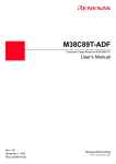
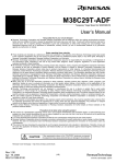
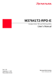
M38C59T-RLFS
Emulator MCU Board for 38C5 Group
User’s Manual
Keep safety first in your circuit designs!
z Renesas Technology Corporation and Renesas Solutions Corporation put the maximum effort into making semiconductor products
better and more reliable, but there is always the possibility that trouble may occur with them. Trouble with semiconductors may lead to
personal injury, fire or property damage. Remember to give due consideration to safety when making your circuit designs, with
appropriate measures such as (i) placement of substitutive, auxiliary circuits, (ii) use of nonflammable material or (iii) prevention
against any malfunction or mishap.
Notes regarding these materials
z These materials are intended as a reference to assist our customers in the selection of the Renesas Technology product best suited
to the customer's application; they do not convey any license under any intellectual property rights, or any other rights, belonging to
Renesas Technology Corporation, Renesas Solutions Corporation or a third party.
z Renesas Technology Corporation and Renesas Solutions Corporation assume no responsibility for any damage, or infringement of
any third-party's rights, originating in the use of any product data, diagrams, charts, programs, algorithms, or circuit application
examples contained in these materials.
z All information contained in these materials, including product data, diagrams, charts, programs and algorithms represents information
on products at the time of publication of these materials, and are subject to change by Renesas Technology Corporation and
Renesas Solutions Corporation without notice due to product improvements or other reasons. It is therefore recommended that
customers contact Renesas Technology Corporation, Renesas Solutions Corporation or an authorized Renesas Technology product
distributor for the latest product information before purchasing a product listed herein. The information described here may contain
technical inaccuracies or typographical errors. Renesas Technology Corporation and Renesas Solutions Corporation assume no
responsibility for any damage, liability, or other loss rising from these inaccuracies or errors. Please also pay attention to information
published by Renesas Technology Corporation and Renesas Solutions Corporation by various means, including the Renesas home
page (http://www.renesas.com).
z When using any or all of the information contained in these materials, including product data, diagrams, charts, programs, and
algorithms, please be sure to evaluate all information as a total system before making a final decision on the applicability of the
information and products. Renesas Technology Corporation and Renesas Solutions Corporation assume no responsibility for any
damage, liability or other loss resulting from the information contained herein.
z Renesas Technology semiconductors are not designed or manufactured for use in a device or system that is used under
circumstances in which human life is potentially at stake. Please contact Renesas Technology Corporation, Renesas Solutions
Corporation or an authorized Renesas Technology product distributor when considering the use of a product contained herein for any
specific purposes, such as apparatus or systems for transportation, vehicular, medical, aerospace, nuclear, or undersea repeater use.
z The prior written approval of Renesas Technology Corporation and Renesas Solutions Corporation is necessary to reprint or
reproduce in whole or in part these materials.
z If these products or technologies are subject to the Japanese export control restrictions, they must be exported under a license from
the Japanese government and cannot be imported into a country other than the approved destination. Any diversion or reexport
contrary to the export control laws and regulations of Japan and/or the country of destination is prohibited.
z Please contact Renesas Technology Corporation or Renesas Solutions Corporation for further details on these materials or the
products contained therein.
Precautions to be taken when using this product
z This product is a development supporting unit for use in your program development and evaluation stages. In mass-producing your
program you have finished developing, be sure to make a judgment on your own risk that it can be put to practical use by performing
integration test, evaluation, or some experiment else.
z In no event shall Renesas Solutions Corporation be liable for any consequence arising from the use of this product.
z Renesas Solutions Corporation strives to renovate or provide a workaround for product malfunction at some charge or without charge.
However, this does not necessarily mean that Renesas Solutions Corporation guarantees the renovation or the provision under any
circumstances.
z This product has been developed by assuming its use for program development and evaluation in laboratories. Therefore, it does not
fall under the application of Electrical Appliance and Material Safety Law and protection against electromagnetic interference when
used in Japan.
CAUTION
Renesas Tools Homepage
Rev.1.00
January 16, 2004
REJ10J0415-0100Z
If the requirements shown in the "CAUTION" sentences are ignored,
the equipment may cause personal injury or damage to the products.
http://www.renesas.com/en/tools
(1/4)
1. Outline
The M38C59T-RLFS is an emulator MCU board for the 38C5
Group.
M38C59T-RLFS
2. Package Components (See Figure 1)
(1) M38C59T-RLFS ......................................................... 1 pc.
(2) M3T-F160-80LCC converter board (preinstalled) ...... 1 pc.
M3T-F160-80LCC
Figure 1 Package components of the M38C59T-RLFS
(3) M38C59T-RLFS User's Manual (This manual) .......... 1 pc.
(4) M38C59T-RLFS User's Manual (Japanese)................ 1 pc.
Emulator
3. Specifications
Table 1 Specifications
Emulator
Operation mode
Max. operating
frequency
Operating power
voltage
(3)
PC4701 + M38000TL2-FPD
M38000T2-CPE
Single-chip mode
Vcc = 4.5 to 5.5 V: 12.5 MHz
Vcc = 4.0 to 5.5 V: 8 MHz
Vcc = 1.8 to 5.5 V: 6 MHz
M38C59T-RLFS
(2)
1.8 to 5.5 V
M3T-F160-80LCC
(4)
4. Connection Procedure (See Figure 2)
LCC socket
The procedure for connecting the M38C59T-RLFS is shown
below.
(1)
(1) Mount an LCC socket on the target system.
(2) Attach the M3T-F160-80LCC to the M38C59T-RLFS
80-pin 0.8-mm-pitch
(80P6U-A) foot pattern
(preinstalled).
(3) Attach the tip of the probe of the emulator to the
M38C59T-RLFS.
: No. 1 pin
Be sure to align the No. 1 pins.
(4) Attach the M3T-F160-80LCC to the LCC socket.
Figure 2 Connection procedure of the M38C59T-RLFS
Before using the M38C59T-RLFS, be sure to read "7.
Precautions" on page 4.
(2/4)
5. Oscillator Circuit (See Figure 3)
This product has two oscillator circuit patterns for the main clock XIN and sub-clock XCIN.
Select one of them according to the oscillator circuitry of the target system.
(1) When using the internal oscillator circuit of the MCU:
The oscillator circuit on the target system may not oscillate because a converter board is used between the emulator MCU and the
target system. In this case, set the jumper switch to INT and mount an oscillator circuit on the M38C59T-RLFS’s oscillator
circuit pattern. When using the oscillator circuit on the target system, be sure to set the jumper switch to EXT.
(2) When using an oscillator module IC etc. (self-oscillation):
It is not necessary to mount an oscillator circuit on the M38C59T-RLFS’s oscillator circuit pattern.
TP2
GND
TP3 TP1
VCC RESET
+
C5
IC1
CN1, CN2
VCC
CN2-5a(VCC)
R1
CN2-2a(RESET*)
RESET*
XCIN
EXT
XCOUT
JP3
EXT
INT
XIN
JP4
XOUT
JP1
INT
EXT
JP2
INT
R3
C4
EXT
CN2-3b(VSS)
INT
R4
C3 X2
CN2-3a(P60)
CN2-2b(P61)
CN2-4a(XIN)
CN2-4b(XOUT)
R2
C1 X1
C2
Figure 3 Oscillator circuit diagram
6. Oscillator Circuit Pattern
JP1 XIN
INT
For 2-terminal oscillator
X1
JP2 XOUT
EXT
INT
JP3 XCIN
EXT
R2
X2
INT
JP4 XCOUT
EXT
C3
INT
R3
For 3-terminal oscillator
R4
C1
C2
C4
Figure 4 Oscillator circuit pattern
(3/4)
EXT
7. Precautions
IMPORTANT
Notes on This Product:
z We cannot accept any request for repair.
z When using the oscillator circuit on the M38C59T-RLFS, check the output waveform of pins XOUT and XCOUT by an
oscilloscope.
z When mounting an oscillator circuit on the M38C59T-RLFS, make sure that 2 mm or more of a DIP pin does not
appear on the rear face (solder side). It may be short-circuited with the DIP pin of the converter board.
z For inquiries about the product or the contents of this manual, contact your local distributor.
Renesas Tools Homepage
http://www.renesas.com/en/tools
8. External Dimensions
64.0
R1 RESET
GND C5
+VCC
12.5
5.4
9.2
C6
45.0
CN2
R6 R5
Unit: mm
Figure 5 External dimensions
9. Connecting to the Target System
M38C59T-RLFS
80-pin 0.8-mm-pitch
80-pin 0.5-mm-pitch
M3T-F160-80LCC
80-pin LCC
(0.8-mm-pitch)
M3T-F160-80LCC
80-pin LCC
(0.8-mm-pitch)
M3T-80LCC-DMS
(Optional)
M3T-FLX100-T
(Optional)
LCC socket
(Optional)
M3T-80LCC-DMS
(Optional)
M3T-FLX100-R M3T-FLX100-T
(Optional)
(Optional)
M3T-FLX100-R
(Optional)
M3T-FLX-80NSD
80-pin LQFP
(Optional)
M3T-FLX-80NRA
80-pin QFP
(Optional)
Figure 6 Connecting to the target system
(4/4)