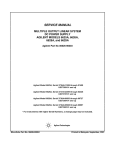
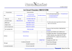
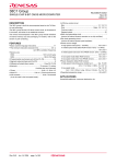
1
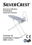
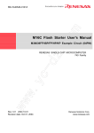
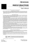
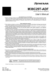
To our customers,
Old Company Name in Catalogs and Other Documents
On April 1st, 2010, NEC Electronics Corporation merged with Renesas Technology
Corporation, and Renesas Electronics Corporation took over all the business of both
companies. Therefore, although the old company name remains in this document, it is a valid
Renesas Electronics document. We appreciate your understanding.
Renesas Electronics website: http://www.renesas.com
April 1st, 2010
Renesas Electronics Corporation
Issued by: Renesas Electronics Corporation (http://www.renesas.com)
Send any inquiries to http://www.renesas.com/inquiry.
Notice
1.
2.
3.
4.
5.
6.
7.
All information included in this document is current as of the date this document is issued. Such information, however, is
subject to change without any prior notice. Before purchasing or using any Renesas Electronics products listed herein, please
confirm the latest product information with a Renesas Electronics sales office. Also, please pay regular and careful attention to
additional and different information to be disclosed by Renesas Electronics such as that disclosed through our website.
Renesas Electronics does not assume any liability for infringement of patents, copyrights, or other intellectual property rights
of third parties by or arising from the use of Renesas Electronics products or technical information described in this document.
No license, express, implied or otherwise, is granted hereby under any patents, copyrights or other intellectual property rights
of Renesas Electronics or others.
You should not alter, modify, copy, or otherwise misappropriate any Renesas Electronics product, whether in whole or in part.
Descriptions of circuits, software and other related information in this document are provided only to illustrate the operation of
semiconductor products and application examples. You are fully responsible for the incorporation of these circuits, software,
and information in the design of your equipment. Renesas Electronics assumes no responsibility for any losses incurred by
you or third parties arising from the use of these circuits, software, or information.
When exporting the products or technology described in this document, you should comply with the applicable export control
laws and regulations and follow the procedures required by such laws and regulations. You should not use Renesas
Electronics products or the technology described in this document for any purpose relating to military applications or use by
the military, including but not limited to the development of weapons of mass destruction. Renesas Electronics products and
technology may not be used for or incorporated into any products or systems whose manufacture, use, or sale is prohibited
under any applicable domestic or foreign laws or regulations.
Renesas Electronics has used reasonable care in preparing the information included in this document, but Renesas Electronics
does not warrant that such information is error free. Renesas Electronics assumes no liability whatsoever for any damages
incurred by you resulting from errors in or omissions from the information included herein.
Renesas Electronics products are classified according to the following three quality grades: “Standard”, “High Quality”, and
“Specific”. The recommended applications for each Renesas Electronics product depends on the product’s quality grade, as
indicated below. You must check the quality grade of each Renesas Electronics product before using it in a particular
application. You may not use any Renesas Electronics product for any application categorized as “Specific” without the prior
written consent of Renesas Electronics. Further, you may not use any Renesas Electronics product for any application for
which it is not intended without the prior written consent of Renesas Electronics. Renesas Electronics shall not be in any way
liable for any damages or losses incurred by you or third parties arising from the use of any Renesas Electronics product for an
application categorized as “Specific” or for which the product is not intended where you have failed to obtain the prior written
consent of Renesas Electronics. The quality grade of each Renesas Electronics product is “Standard” unless otherwise
expressly specified in a Renesas Electronics data sheets or data books, etc.
“Standard”:
8.
9.
10.
11.
12.
Computers; office equipment; communications equipment; test and measurement equipment; audio and visual
equipment; home electronic appliances; machine tools; personal electronic equipment; and industrial robots.
“High Quality”: Transportation equipment (automobiles, trains, ships, etc.); traffic control systems; anti-disaster systems; anticrime systems; safety equipment; and medical equipment not specifically designed for life support.
“Specific”:
Aircraft; aerospace equipment; submersible repeaters; nuclear reactor control systems; medical equipment or
systems for life support (e.g. artificial life support devices or systems), surgical implantations, or healthcare
intervention (e.g. excision, etc.), and any other applications or purposes that pose a direct threat to human life.
You should use the Renesas Electronics products described in this document within the range specified by Renesas Electronics,
especially with respect to the maximum rating, operating supply voltage range, movement power voltage range, heat radiation
characteristics, installation and other product characteristics. Renesas Electronics shall have no liability for malfunctions or
damages arising out of the use of Renesas Electronics products beyond such specified ranges.
Although Renesas Electronics endeavors to improve the quality and reliability of its products, semiconductor products have
specific characteristics such as the occurrence of failure at a certain rate and malfunctions under certain use conditions. Further,
Renesas Electronics products are not subject to radiation resistance design. Please be sure to implement safety measures to
guard them against the possibility of physical injury, and injury or damage caused by fire in the event of the failure of a
Renesas Electronics product, such as safety design for hardware and software including but not limited to redundancy, fire
control and malfunction prevention, appropriate treatment for aging degradation or any other appropriate measures. Because
the evaluation of microcomputer software alone is very difficult, please evaluate the safety of the final products or system
manufactured by you.
Please contact a Renesas Electronics sales office for details as to environmental matters such as the environmental
compatibility of each Renesas Electronics product. Please use Renesas Electronics products in compliance with all applicable
laws and regulations that regulate the inclusion or use of controlled substances, including without limitation, the EU RoHS
Directive. Renesas Electronics assumes no liability for damages or losses occurring as a result of your noncompliance with
applicable laws and regulations.
This document may not be reproduced or duplicated, in any form, in whole or in part, without prior written consent of Renesas
Electronics.
Please contact a Renesas Electronics sales office if you have any questions regarding the information contained in this
document or Renesas Electronics products, or if you have any other inquiries.
(Note 1) “Renesas Electronics” as used in this document means Renesas Electronics Corporation and also includes its majorityowned subsidiaries.
(Note 2) “Renesas Electronics product(s)” means any product developed or manufactured by or for Renesas Electronics.
M38D29T2-RLFS
Emulator MCU Board for 38D2 Group
User’s Manual
CAUTION
Renesas Tools Homepage
Rev.1.00
Jan. 10, 2008
REJ10J1789-0100
If the requirements shown in the "CAUTION" sentences are ignored,
the equipment may cause personal injury or damage to the products.
http://www.renesas.com/tools
(1/4)
1. Outline
The M38D29T2-RLFS is an emulator MCU board for the 38D2 Group.
2. Package Components
(1) M38D29T2-RLFS
1 pc.
(2) M38D29T2-RLFS User's Manual (This manual)
1 pc.
(3) M38D29T2-RLFS User's Manual (Japanese)
1 pc.
The M3T-F160-64NSA is included with the M38D29T2-RLFS-FP.
The M3T-F160-64NSD is included with the M38D29T2-RLFS-HP.
For details on the M3T-F160-64NSA and M3T-F160-64NSD, refer to each user’s manual.
3. Specifications
Table 1 Specifications
Emulator
Operation mode
Max. operating
frequency
Operating power
voltage
M38000T2-CPE
PC4701 + M38000TL2-FPD
Single-chip mode
Vcc = 4.5 to 5.5V: 12.5MHz (frequency/2 mode)
Vcc = 4.0 to 5.5V: 8.0MHz (frequency/2 mode)
Vcc = 2.0 to 5.5V: 4.0MHz (frequency/2 mode)
Vcc = 1.8 to 5.5V: 2.0MHz (frequency/2 mode)
Vcc = 4.5 to 5.5V: 16.0MHz (frequency/4 mode)
Vcc = 3.1 to 5.5V: 12.5MHz (frequency/4 mode)
Vcc = 2.0 to 5.5V: 8.0MHz (frequency/4 mode)
Vcc = 1.8 to 5.5V: 4.0MHz (frequency/4 mode)
Vcc = 4.5 to 5.5V: 16.0MHz (frequency/8 mode)
Vcc = 2.0 to 5.5V: 12.5MHz (frequency/8 mode)
Vcc = 1.8 to 5.5V: 8.0MHz (frequency/8 mode)
Vcc = 1.8 to 5.5V: Low-speed mode
1.8 to 5.5 V
4. Connecting the User System
M38D29T2-RLFS
M38D29T2-RLFS
64-pin 0.5mm pitch
64-pin 0.8mm pitch
M3T - F 160 - 64NSD
(included)
M3T - F 160 - 64NSA
(included)
Figure 1 M38D29T2-RLFS-FP
Figure 2 M38D29T2-RLFS-HP
(2/4)
5. Connection Procedure
(1) For M38D29T2-RLFS-FP
1 Mount the NQPACK064SA160 to the foot pattern of the user system.
2 Attach the included M3T-F160-64NSA to the M38D29T2-RLFS.
3 Mount the YQPACK064SA on the NQPACK064SA160.
4 Attach the tip of the probe of the emulator to the M38D29T2-RLFS, and connect the M38D29T2-RLFS and YQPACK064SA.
(2) For M38D29T2-RLFS-HP
1 Mount the NQPACK064SD-ND to the foot pattern of the user system.
2 Attach the included M3T-F160-64NSD to the M38D29T2-RLFS.
3 Mount the YQPACK064SD on the NQPACK064SD-ND.
4 Attach the tip of the probe of the emulator to the M38D29T2-RLFS, and connect the M38D29T2-RLFS and YQPACK064SD.
Emulator
Emulator
(4)
(4)
M38D29T2 - RLFS
M38D29T2 - RLFS
(2)
(2)
M3T-F160-64NSD
M3T- F 160- 64 NSA
(4)
(4)
YQ- GUIDE (x4)
YQ - GUIDE (x4)
YQPACK064SD
YQPACK 064 SA
(3)
(3)
NQPACK 064SD - ND
NQPACK 064SA160
(1)
(1)
PLQP 0064 KB - A ( 64P6Q- A )
64-pin 0.5mm pitch
foot pattern
PLQP 0064GA- A ( 64P6U-A)
64-pin 0.8mm pitch
foot pattern
●: No. 1 pin
●: No. 1 pin
Be sure to align the pins.
Be sure to align the pins.
Figure 3 Connection procedure of M38D29T2-RLFS-FP
Figure 4 Connection procedure of M38D29T2-RLFS-HP
6. External Dimensions
64. 0
R1
RESET
GNDC 5 +VCC
45.0
5.4
9.2
C6
CN2
R6 R5
Figure 5 External dimensions
(3/4)
7. Oscillator Circuit
This product has two oscillator circuit patterns for the main clock XIN and sub-clock XCIN. Figures 6 and 7 show the oscillator
circuit diagram and oscillator circuit pattern, respectively. Select one of them according to the oscillator circuitry of the user system.
(1) When using the internal oscillator circuit of the MCU:
The oscillator circuit on the user system may not oscillate because a converter board is used between the emulator MCU and the
user system. In this case, set the jumper switch to INT and mount an oscillator circuit on the M38D29T2-RLFS’s oscillator
circuit pattern. When using the oscillator circuit on the user system, be sure to set the jumper switch to EXT.
(2) When using an oscillator module IC etc. (self-oscillation):
It is not necessary to mount an oscillator circuit on the M38D29T2-RLFS’s oscillator circuit pattern.
TP 2
GND
TP3
TP1
VCC RESET
+
C5
IC1
CN1,CN 2
CN2 - 5b (VCC)
VCC
R1
CN2 - 2b (RESET*)
RESET
*
CN1 - 12a ( Vref )
Vref
C6
CN1 - 12b ( AVss)
AVss
XCIN
XCOUT
XIN
XOUT
CN2 - 3b (P61 / Xcin )
CN2 - 3a (P62 / Xcout )
CN2 - 4b ( Xin )
JP 3
JP4
JP1
CN2 - 5a ( Xout )
JP2
EXT
EXT
EXT
EXT
INT
INT
INT
INT
CN2 - 4a ( Vss)
R3
R4
R2
X2
C3
X1
C4
C1
C2
Figure 6 Oscillator circuit diagram
JP1 XIN
INT
For 2-terminal oscillator
X1
JP2 XOUT
EXT
INT
JP3 XCIN
EXT
R2
X2
INT
JP4 XCOUT
EXT
C3
INT
EXT
R3
For 3-terminal oscillator
R4
C1
C2
C4
Figure 7 Oscillator circuit pattern
8. Precautions
IMPORTANT
Notes on This Product:
z We cannot accept any request for repair.
z When using the oscillator circuit on the M38D29T2-RLFS, check the output waveform of pins Xout and Xcout by
an oscilloscope.
z When mounting an oscillator circuit on the M38D29T2-RLFS, make sure that 2 mm or more of a DIP pin does not
appear on the rear face (solder side). It may be short-circuited with the DIP pin of the converter board.
z For inquiries about the product or the contents of this manual, contact your local distributor.
Renesas Tools Homepage
http://www.renesas.com/tools
(4/4)