1
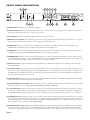
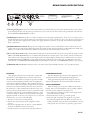
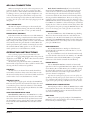
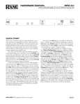
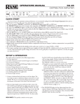
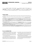
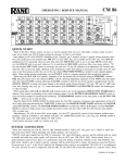
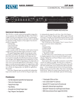
OPERATORS MANUAL
AD 22d
AUDIO DELAY
1
SENSITIVITY
-10 dBV
-8
-12
-4
0
-16
+4
SIGNAL
-20
dBu
2
SENSITIVITY
-10 dBV
-8
-12
0
2
A
B
1
2
-16
+4
CLIP
1
-4
SIGNAL
-20
dBu
MILLISECONDS
FEET
BYPASS
CLIP
DISPLAY
MODE
STORE RECALL CHAN
MEMORY
1 ms
10 μs
COARSE
FINE
AD 22d
AUDIO DELAY
METERS
HOLD TO SET TEMP
°C
°F
QUICK START
Quickly look around to make sure no one catches you reading this. You’re aware this is the manual aren’t you? Wow! Most
people only get about this far in a manual, but there are a few
important things you should know about the AD 22d. So please
keep reading. These few points are summarized in this Cliff Note
version of the manual.
ADJUSTING SENSITIVITY. First apply a signal with
nominal input level and adjust the SENSITIVITY controls so
the red CLIP LEDs just light, then back off so the LEDs do not
turn on, even with high signal peaks.
SETTING DELAY. Now that the input signal is calibrated,
press the CHAN button until the CHAN LEDs indicate the
channel you want to set. We cover the special case of adjusting
both channels simultaneously later (both CHAN LEDs on).
Adjust the up/down buttons until the LED display shows the
desired Delay. To adjust the Delay of the other channel press the
CHAN button until the other channel’s LED is lit, and adjust
the Delay as before.
STORING DELAY. Press the STORE button (the STORE
LED stops flashing). This stores the current Delay values into
each channel’s current Memory (A or B). The current Memory
for each channel is indicated by the MEMORY LED lit when
editing that channel. Both channel's current Delay values are
stored with each press of the STORE button.
WEAR PARTS: This product contains no wear parts.
RECALLING DELAY. To recall a stored Memory, press
RECALL. Each press of this button alternately recalls stored
Memories (A then B then A…) for the selected channel only.
A quick way to recall Memories into both channels simultaneously, is to store both channel’s values into the same Memory.
With both channels selected (both CHAN LEDs on), press
RECALL to restore both channel’s Memories at the same time.
SETTING TEMPERATURE. The AD 22d is factory set for
22°C/71.6°F. To change this, press and hold DISPLAY MODE
and press one of the up/down buttons. Use the 1ms/COARSE
buttons for degrees Celsius or the 10µs/FINE buttons for degrees
Fahrenheit. The LED display shows the temperature setting.
Further pressing of the up/down buttons adjusts the temperature
setting. This temperature is used, with constant 30% humidity,
to calculate the speed of sound for converting delay times into
distance.
Never connect anything except an approved Rane power supply
to the red thing that looks like a telephone jack on the rear of the
unit. This is an AC input and requires special attention if you do
not have a power supply exactly like the one originally packed
with your unit. See the full explanation of the power supply
requirements elsewhere in this manual.
Note: Changing the Delay setting is nearly seamless, though a
single audio click may be expected if an audio signal is present.
Manual-
FRONT PANEL DESCRIPTION
1
1
4 5 7 9
2 3
SENSITIVITY
-10 dBV
-8
-12
2
-4
0
-16
+4
SIGNAL
SENSITIVITY
-10 dBV
-8
-12
0
-20
dBu
2
A
B
1
2
BYPASS
CLIP
2
MILLISECONDS
FEET
-20
dBu
SIGNAL
1
DISPLAY
MODE
-16
+4
CLIP
1
-4
11
3
STORE RECALL CHAN
MEMORY
6 8 10
1 ms
10 μs
COARSE
FINE
AD 22d
AUDIO DELAY
METERS
HOLD TO SET TEMP
14
°C
12
°F
13
1 SIGNAL LEDs: illuminate green 34 dB before clipping.
2 SENSITIVITY controls: vary incoming signal levels to the A to D converter. The output signal is also adjusted so the AD 22d
always passes signal with unity gain. (See operating instructions.)
3 CLIP LEDs: illuminate red 4 dB before clipping at the A to D converter input.
4 BYPASS buttons & LEDs: These momentary push buttons toggle each channel’s hard-wired Bypass. If an LED is on, the given
channel is Bypassed and functions like a wire. If it is off the given channel is active.
5 STORE LED: flashes green when the current configuration of the AD 22d is different from the stored configuration. The
STORE LED is off when the current configuration matches the stored configuration.
6 STORE button: Stores the current Delay configuration into both channel’s current Memory (A or B). The current Memory for
each channel is indicated by the MEMORY LED which is lit when editing that channel.
7 MEMORY LEDs: indicate the most recently recalled Memory, A or B, for each channel by illuminating yellow. They also indicate the Memory that is written to when the STORE button is pressed. The MEMORY LED flashes when the current Delay value
for the selected channel is different than the stored value for the selected channel.
8 RECALL button: Pressing this pushbutton alternately Recalls stored Memories A and B, for the channels(s) indicated by the
green CHAN LEDs.
9 CHANNEL LEDs: indicate the channel number whose value is currently being displayed in the LED display and whose current
Delay value is editable by illuminating green. If both CHAN LEDs are on, both channel’s current Delay values are editable. In this
edit BOTH mode, the LED display shows the smaller of the two current Delay values and the memory LEDs turn off if the two
channel’s current Memories are not the same.
0 CHANNEL button: Pressing this button advances the channel LEDs from CHAN 1 to CHAN 2 to BOTH. The current Delay
value of the selected channel is displayed in the LED display.
q DISPLAY MODE button & LEDs: This button changes the units of displayed Delay values from Milliseconds to Feet to Meters.
The LEDs indicate the current Display Mode: MILLISECONDS, FEET or METERS.
w 5-digit LED display: indicates the current Delay value for the selected channel. When both channels are selected, the smaller of
the two channel’s current Delay values is displayed. This display also shows the current temperature setting when holding down
the DISPLAY MODE button and pressing one of the up/down buttons. On power-up the current software revision is displayed.
e UP/DOWN buttons: Pressing these buttons increases/decreases the amount of Delay in the selected Channel(s). The two buttons
just to the right of the LED display change Delay time in 1 millisecond steps. The far right buttons provide 10 microsecond steps.
For distance displays (feet and meters), these buttons are FINE and COARSE adjustments, since Delay increments are always in 1
msec and 10 µsec steps, regardless of the DISPLAY MODE.
r TEMPERATURE setting: Holding down DISPLAY MODE while pressing the up/down buttons displays the current temperature setting in degrees Celsius for the 1 msec/COARSE buttons and degrees Fahrenheit for the 10 µsec/FINE buttons. Further
up/down presses change the temperature setting. No matter which unit (°C or °F), adjustments are always in 1°C steps (or 1.8°F).
Manual-
REAR PANEL DESCRIPTION
REMOTE RECALL
POWER
650mA
CLASS 2 EQUIPMENT
1
2
OPEN
MEM A
CH 2 OUT
CH 2 IN
CH 1 OUT
CH 1 IN
BALANCED WIRING:
PIN 2 POSITIVE
PIN 3 NEGATIVE
PIN 1 CHASSIS GND
CLOSED
MEM B
CH1
CH2
3
GND
CH 2 OUT
4
CH 2 IN
CH 1 OUT
REMOTE RECALL PORT:
5 VOLT SOURCES 0.5 mA
CMOS SCHMITT TRIGGER INPUTS
THIS DEVICE COMPLIES WITH PART 15 OF THE FCC
RULES. OPERATION IS SUBJECT TO THE FOLLOWING
TWO CONDITIONS: (1) THIS DEVICE MAY NOT CAUSE
HARMFUL INTERFERENCE, AND (2) THIS DEVICE MUST
ACCEPT ANY INTERFERENCE THAT MAY CAUSE
UNDESIRED OPERATION.
AD 22d
MADE IN U.S.A.
RANE CORP.
ACN 001 345 482
CH 1 IN
5
1 Chassis ground point: A #6-32 screw and toothed washer is provided for chassis ground. Since the AD 22d does not get chassis
ground through the AC cord, this point is provided in case your system does not have another earth ground such as the rack rails.
See the CHASSIS GROUNDING note below.
2 POWER input connector: No this is not where Commissioner Gordon plugs in his Bat-phone, in fact it is not a telephone jack at
all. The AD 22d uses an 18 volt AC center-tapped transformer only. Use only a model RS 1 or other remote AC power supply approved
by Rane. The AD 22d is supplied with a remote power supply suitable for connection to this jack. Consult the factory for replacement or substitution.
3 REMOTE RECALL terminals: Wiring external configuration switches to these terminals allows remote recall of the two nonvolatile memories for each Channel. When the switch closes, Memory B for the given Channel is recalled. When the switch opens,
Memory A is recalled. These terminals use CMOS (+5 volt) logic levels and sink only 0.5 mA (max.) each.
4 Recessed lockout switch: Enables the Front Panel Lockout mode. In this mode all front panel controls, with the exception of the
CHAN and DISPLAY MODE buttons, are disabled. The Channel button remains active so the user may view the current Delay
values without risk of changing them, and the display mode button allows display of Delay values in milliseconds, feet or meters.
Press RECALL while in LOCKOUT to temporarily display, but not Recall, the value of the other stored Memory for the indicated channel. (See OPERATING INSTRUCTIONS for optional Bypass lockout mode, and MEMORY BUTTONS on previous page.)
5 INPUT/OUTPUT connectors: Nothing new here, the AD 22d uses balanced XLRs, with pin 2 “hot” per AES standards.
FCC NOTICE
This equipment has been tested and found to comply with
the limits for a Class B digital device, pursuant to Part 15 of
the FCC Rules. These limits are designed to provide reasonable
protection against harmful interference when the equipment is
operated in a residential installation. This equipment generates,
uses, and can radiate radio frequency energy and, if not installed
and used in accordance with the instructions, may cause harmful interference to radio communications. However, there is no
guarantee that interference will not occur in a particular installation. If this equipment does cause harmful interference to radio
or television reception, which can be determined by turning the
equipment off and on, the user is encouraged to try to correct the
interference by one or more of the following:
1. Re-orient or relocate the receiving antenna.
2. Increase the separation between the equipment and the
receiver.
3. Connect the equipment into an outlet on a circuit different
from that to which the receiver is connected.
4. Consult the dealer or an experienced radio/TV technician.
CANADIAN EMC NOTICE
This Class B digital apparatus meets all requirements of the
Canadian Interference-Causing Equipment Regulations.
Cet Appariel numerique de la classe B respecte toutes les
exigences du Reglement sur le material broilleur du Canada.
CHASSIS GROUNDING
If after hooking up your system it exhibits excessive hum or
buzzing, there is an incompatibility in the grounding configuration between units. Here are some things to try:
1. Try combinations of lifting grounds on units supplied with
ground lift switches (or links).
2. Verify all chassis are tied to a good earth ground.
3. Some units with outboard power supplies do not ground
the chassis through the line cord. Make sure these units are
solidly grounded by tying the Chassis Ground Point to known
earth ground. Use a star washer to guarantee proper contact.
Manual-
AD 22d CONNECTION
When connecting the AD 22d to other components in your
system for the first time, leave the power supply for last. This
gives you a chance to make mistakes and correct them before
any damage is done to your fragile speakers, headphones, ears,
or brains. The AD 22d passes audio while it is unpowered by
virtue of its fail safe bypass relays (when the AD 22d functions
as a wire). Turn the system volume down before plugging in the AD
22d’s power.
INPUTS AND OUTPUTS
The AD 22d’s Inputs and Outputs are electronically balanced, so use only balanced wiring. The AD 22d’s shields (pin 1)
connect to chassis ground. Pin 2 is “hot” per AES standards.
REMOTE RECALL TERMINALS
Each channel of the AD 22d has two nonvolatile Memories,
“A” and “B”. Connecting a switch between the GND and CH1
or CH2 terminals permits recalling the Memories remotely.
Only a change in the switch position is sensed—when the switch
closes, Memory B for the given channel is recalled. When the
switch opens, Memory A is recalled. Connecting the two channel terminals (CH1 & CH2) together on one side of the same
switch, permits stereo recall of Memories A and B.
OPERATING INSTRUCTIONS
Once you have properly connected the AD 22d to the
system, turn on the power. When the AD 22d is first powered it
displays the words “RANE” and “Ad 22”. Then, the unit’s software
revision level is briefly displayed.
The first time you power the AD 22d it is in BYPASS, and
functions like an expensive wire. This is useful for initial troubleshooting and allows verification of signal flow.
THE BASICS
The AD 22d is a two channel device. Each channel has a
current Delay value that is always active/heard. You can only
edit the current Delay values in each channel, which can then be
stored in either of two nonvolatile Memories, A and B.
SENSITIVITY SETUP
The first step is to apply signal, and adjust the SENSITIVITY controls. If you know the nominal level, adjust the control
so its indicator points to that level. Otherwise, set the SENSITIVITY control so high signal peaks just illuminate the CLIP
indicator, then back off a little.
ADJUSTING CURRENT DELAY VALUE
One Channel at a time: Press the CHAN button to select
the desired channel. The LED display shows the current Delay
value of the selected channel. Press the up/down buttons until
the desired Delay value is reached. That’s it! Press the CHAN
button until the other CHAN LED is lit and edit its current
Delay value.
Both channels simultaneously: If you’ve selected both
channels (both CHAN LEDs on), the LED display shows the
smaller of the two channel’s current Delay values. Changing
this value changes the other channel’s value by the same relative amount. Check the other channel’s current Delay value by
selecting it with the CHAN button. There are two things to be
careful of at this point: The first is to pay close attention to the
CHAN LEDs that indicate the channel you are viewing, it cycles
from CHAN 1 to CHAN 2 to both and back again. (both always
displays the lower of the two channel’s current Delay values.) The
second gotcha at this point is pressing the RECALL button. This
writes over the changes you’ve made if you have not stored them.
STORING DELAYS
Press the STORE button. The STORE LED stops flashing.
This Stores the current Delay values into each channel’s current Memory (A or B). The current Memory for each channel is
indicated by the MEMORY LED which is lit when editing that
channel. Both channel's current Delay values are Stored with each
press of the STORE button.
RECALLING DELAYS
Press the RECALL button. Each press of this button alternately Recalls stored Memories (A then B then A…) for the
selected channel only.
Tip: To recall Memories into both channels simultaneously,
store both channel’s values into the same Memory– A or B. With
both channels selected (both CHAN LEDs on), pressing RECALL causes both channels to Recall the same Memory.
REMOTE RECALLS
The rear REMOTE RECALL terminals are functionally
equivalent to the front panel RECALL button. When the switch
closes, Memory B is recalled. Memory A is recalled by opening
the switch. These terminals can not be locked out. When both
channel’s terminals are wired with a single switch for Stereo
operation, channel 1 is displayed.
Tip: Note the weather forecast for your event’s time of day. Set
up Memory A’s Delay value for your stack’s distance at one temperature, and Memory B’s value for a different temperature. Then during the warmer part of the day, recall Memories to suit the climate.
INTERNAL BYPASS JUMPER SETTING
Internal jumpers enable or disable the BYPASS buttons while
in Front Panel Lockout mode. The default setting of these jumpers disables the BYPASS buttons in Front Panel Lockout mode.
(See enclosed drawing 103473.)
HOLE PLUGS
Once your system is properly configured, the SENSITIVITY knobs can be removed and the unit secured by replacing the
knobs with the provided hole plugs.
©Rane Corporation 10802 47th Ave. W., Mukilteo WA 98275-5098 TEL 425-355-6000 FAX 425-347-7757 WEB www.rane.com
Manual-
103489