1
THE BULLSHOOTER
ENDLESS LOOP
VOICE RECORDER
Ramsey Electronics Model No.
BS1
Announcing an event is now easier than ever! Just say it once
and hear it over and over. Easy transmitter hookup for
broadcasting.
•
Compact design stores up to 8 full minutes of audio.
•
Provides endless looping playback of any message…FOREVER !!
•
Add a transmitter for error free broadcasting of repetitive
announcements. “This Cape Cod rests on 12 acres with…”
•
Easy to use, pushbutton operation - No fumbling around!
•
Convenient line and speaker level outputs for any application.
•
Handy built in microphone for use “on the fly” and external input for
pre-recorded messages.
•
Operates on 9 to 15 Volts DC.
•
Clear, concise instructions guide you step-by-step to a finished
product that works FIRST time.
BS-1 • 1
RAMSEY TRANSMITTER KITS
• FM100B Professional FM Stereo Transmitter
• FM25B Synthesized Stereo Transmitter
• AM1, AM25 AM Transmitters
• TV6 Television Transmitter
RAMSEY RECEIVER KITS
• FR1 FM Broadcast Receiver
• AR1 Aircraft Band Receiver
• SR2 Shortwave Receiver
• AA7 Active Antenna
• SC1 Shortwave Converter
RAMSEY HOBBY KITS
• SG7 Personal Speed Radar
• SS70A Speech Scrambler
• SP1 Speakerphone
• WCT20 Wizard Cable Tracer
• PH10 Peak hold Meter
• LC1 Inductance-Capacitance Meter
RAMSEY AMATEUR RADIO KITS
• DDF1 Doppler Direction Finder Kit
• HR Series HF All Mode Receivers
• QRP Series HF CW Transmitters
• CW700 Micro Memory CW Keyer
• CPO3 Code Practice Oscillator
• QRP Power Amplifiers
RAMSEY MINI-KITS
Many other kits are available for hobby, school, Scouts and just plain FUN. New
kits are always under development. Write or call for our free Ramsey catalog.
ENDLESS LOOP VOICE RECORDER INSTRUCTION MANUAL
Ramsey Electronics publication No. MBS1 Rev 1.0
First printing: August 1999
COPYRIGHT 1996 by Ramsey Electronics, Inc. 590 Fishers Station Drive, Victor, New York
14564. All rights reserved. No portion of this publication may be copied or duplicated without the
written permission of Ramsey Electronics, Inc. Printed in the United States of America.
BS-1 • 2
Ramsey Publication No. MBS-1
Price $5.00
KIT ASSEMBLY
AND INSTRUCTION MANUAL FOR
THE BULLSHOOTER
ENDLESS LOOP
VOICE RECORDER
TABLE OF CONTENTS
Introduction .............................................4
Circuit Description ..................................5
BS1 Parts List .........................................6
Parts Layout Diagram .............................8
Assembly Procedure ..............................9
Schematic Diagram ..............................10
Initial Testing and Operation.................16
Troubleshooting ....................................18
Warranty ...............................................19
RAMSEY ELECTRONICS, INC.
590 Fishers Station Drive
Victor, New York 14564
Phone (585) 924-4560
Fax (585) 924-4555
www.ramseykits.com
BS-1 • 3
INTRODUCTION
Each of us at one time or another has probably heard an endless loop player
repeating a list of movies playing at the local theatre, or advertising a house for
sale through your car radio. Sure could be handy around the house
occasionally, or maybe down at the local flea market. Could you modify a
cassette or CD player to duplicate this function? Good luck! Where could you
even find that sort of machine anyway, and how much would it cost? Enter the
BS1 Bullshooter.
As a stand alone unit, the BS1 is perfect for the task of, say, announcing
repetitive instructions at an event: “All vendors please report to the registration
desk located at the …“. Connected to one of our personal broadcasters like the
FM-25, the BS1 is ideal for advertising neighborhood garage sales or school or
church functions. How about a look at the BS1?
You will notice right away that the Bullshooter isn’t your average tape player. In
fact, utilizing one of the latest voice recording chips on the market, the BS1
performs its job without need of a tape. There are no motors, drive belts, or
gears to wear out. With the exception of the front panel controls, there are no
moving parts at all! In addition, the endless loop playback feature makes the
Bullshooter a truly unique device.
A quick push of the “Record” button sets up the BS1 to record up to a full eight
minutes of audio. Use the on-board microphone to record a quick message or
move the pc board mounted jumper to enable use of the line level input for
recording from other sources; cassette, CD, radio, etc. A “Record” LED serves
as the record mode indicator and extinguishes when the maximum memory
capacity has been reached.
The “Play” button selects playback mode which is automatically set up for
endless loop operation. The message recorded will continue playback
indefinitely, looping over and over for as long as the unit remains in play mode.
Through programming of the internal microcontroller the message will always
start from the beginning, thus negating the need for rewinding. The “Play” LED
simply serves as an indicator for playback mode.
The Bullshooter features two sets of audio outputs to best suit the application
at hand. The speaker output (volume controlled by the front panel volume knob)
has sufficient power to drive most speakers well into normal listening volumes.
Although being a monaural device, twin line level outputs are provided for
connection to equipment such as mixers, amplifiers, or transmitters which
would normally require left and right inputs.
BS-1 • 4
BS1 CIRCUIT DESCRIPTION
In the BS1, as in all electronic devices, specific power and voltage
requirements exist. Although appearing quite simple at a glance, the power
supply of this unit provides three separate outputs (+12V unregulated, +5V, and
+3V regulated.) The +12V comes from an external source such as battery or
wall adapter and is filtered or “smoothed” by capacitor C21. D4 is a reverse
polarity protection diode which acts as a switch for the applied voltage. If proper
polarity is observed, D4 is forward biased and simply turns on like a switch.
However, if for some reason the applied voltage is reversed, D4 becomes
reverse biased and turns off, thus protecting all components. VR1 is a voltage
regulator which takes the raw +12V and provides a very clean +5 volts output.
D1, D2, and D3 together drop about 2 volts leaving a nice clean +3 volts
required by U2.
Most of the “magic” inside the BS1 lies within the ISD4004 IC (U2). This unique
chip manages all the recording, audio storage, and playback functions requiring
only address and control information from the microcontroller. An internal 8kHz
sampling frequency provides high quality voice reproduction. A four-wire serial
peripheral interface provides the means of data transfer into and out of the chip.
If the ISD4004 IC were the “heart” of the BS1, then the 68HC705K1
microcontroller (U4) would be the “brains” of the outfit. The micro takes inputs
from the pushbutton switches and through the use of an internal program,
processes this information in order to light the LEDs and send data to control
the voice chip. R15 and C18 with U4 set up an oscillator used for timing
purposes.
U1, the LM358 is a dual opamp by trade. One side (U1:A) is used as an active
low-pass filter with supporting components R9, C4 and R10, C10. A low-pass
filter is used to prevent any undesired high frequency noise from U2 and U4
from passing on to the audio amplifiers, degrading the audio output. U1:B is
used as an audio amplifier to increase the small signal of U2 to a line level
sufficient for driving a high power amplifier or to feed into a transmitter for
broadcasting. The LM386 is self contained audio amplifier which is used here to
amplify our audio up to about half a watt, which will drive the average sized
speaker to comfortable listening levels.
The on-board jumper J2 selects either the microphone or external line level
inputs for recording.
BS-1 • 5
PARTS SUPPLIED WITH BS1 VOICE RECORDER KIT
Capacitors
1 .0047 µF or .005 µF disc capacitor (marked 472, .005, or 502) [C4]
1 .002 µF or .0022 µF disc capacitor (marked .002, 202 or 222) [C10]
3 .01 µF disc capacitors (marked .01, 103, or 10 nF) [C14,C16,C17]
4 .1 µF disc capacitors (marked .1, 104, or 100 nF) [C3,C5,C9,C19]
1 100 pF disc capacitor (marked 100 or 101) [C18]
1 1 µF electrolytic capacitor [C11]
8 10 µF electrolytic capacitors [C1,C2,C6,C7,C8,C13,C20,C22]
2 220 µF electrolytic capacitors [C12,C15]
1 470 µF electrolytic capacitor [C21]
Resistors
1 2 ohms (red-black-gold) [R14]
1 100 ohms (brown-black-brown) [R3]
1 470 ohms (yellow-violet-brown) [R16]
3 1K ohms (brown-black-red) [R4,R7,R15]
1 4.7K ohms (yellow-violet-red) [R6]
7 10K ohms (brown-black-orange) [R1,R8,R9,R10,R11,R13, one for the
bottom of the board]
1 15K ohms (brown-green-orange) [R5]
1 1K ohm potentiometer (marked 102) [R2]
1 PC mount 10K ohm trimmer potentiometer (marked 10K) [R12]
Semiconductors
3 1N4148 diodes (small glass diodes) [D1,D2,D3]
1 1N4002 diode (epoxy case marked 1N4004) [D4]
1 Red LED [D5]
1 Green LED [D6]
1 7805 +5 Volt voltage regulator [VR1]
1 LM358 Dual Opamp IC [U1]
1 ISD4004 Voice Recorder IC [U2]
1 LM386 Audio Amplifier IC [U3]
1 68HC705K1 Microcontroller IC (marked with white sticker) [U4]
Hardware, Misc.
3 Horizontal push-button switch [S1,S2,S3]
1 3 pin vertical header strip and jumper block [J2]
1 .5 mm center pin type power jack [J5]
3 RCA-style jacks [J1,J3,J6]
1 Subminiature speaker jack [J4]
1 16-pin socket for U4
1 28-pin socket for U2
1 MC-1 microphone cartridge [MIC1]
BS-1 • 6
1
BS1 printed circuit board
Required, not supplied
12 Volt DC power transformer
Optional
Line level audio source (such as a tape deck or CD player)
Shielded stereo audio cables
Speaker
Case and Knob Parts
Top Cover
Bottom Base Tray
4 - Short Phillips Head Screws
2 - Long Phillips Screws
Front and Rear Plastic Panels
Front and Rear Labels
4 - Rubber Feet
Appropriate Knobs for Kit
Required Tools
Pen or Pencil
Sharp hobby knife or hand held paper punch
Small Phillips Head Screwdriver
BS-1 • 7
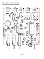
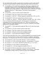
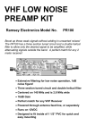
BS1 PARTS LAYOUT DIAGRAM
BS-1 • 8
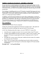
RAMSEY "LEARN-AS-YOU-BUILD" ASSEMBLY STRATEGY
As you can see in examining the circuit board and components, there is a bit
more to this voice recorder kit than just soldering a few parts. So that you don't
spend extra time "troubleshooting" instead of enjoying your new kit, we strongly
recommend that you follow the assembly strategy and step-by-step procedures
we provide.
Our strategy in installing parts on our PC board is to install the larger and more
obvious parts such as the connectors and controls. These parts will then act as
"landmarks" so that each additional device installed is seen in relationship to
them, or to others previously installed.
In addition, we'll discuss the purpose of most of the components or groups of
components as we go along. If you are new to the idea of building your own kit,
perhaps our explanations will help you understand and learn as we go along.
The assembly sequence will complete operational blocks as faithfully as is
practical, as part of Ramsey's "Learn-As-You-Build" kit assembly philosophy.
BS1 ASSEMBLY
Use the boxes to check off your progress.
Check all received parts against the Parts list on page 6 and 7. The parts list
describes the various markings that may be found on the kit parts.
In ALL the following instruction steps, our word "INSTALL" means this:
•
Insert the part, oriented correctly, into its correct holes in the PC board.
•
If helpful, gently BEND the part's wire leads or tabs to hold it in place, with
the body of the part snugly against the top "component side" of the PC
board.
•
SOLDER ALL wires or pins of the part, whether the two wires of a resistor
or every pin of an IC socket.
•
Nip or "trim" all excess wires extending beyond each solder connection,
taking care that wire trimmings do not become lodged in PC board solder
connections.
Enough said. . . Let's get building!
BS-1 • 9
BS-1 • 10
BS-1 • 11
Since you may appreciate some “warm-up” soldering practice as well as a
chance to put some “landmarks” on the PC board, we’ll first install some of the
larger components. Have a look at the Parts Layout Diagram to help with your
assembly.
1. Install S2, the Power DPDT horizontal push-button switch. It fits correctly
only one way. Ensure that the white plastic switch extends out over the
edge of the printed circuit board. Solder all six pins.
2. Install S1, the Record DPDT horizontal push-button switch.
3. Install S3, the Play DPDT horizontal push-button switch.
4. Install J5, the power jack. Solder all 3 pins.
5. Install J4, the sub-miniature speaker jack. Solder all 3 points of the jack
securely.
6. Install J6, the RCA jack (line input). Solder all 4 pins.
7. Install the two remaining RCA jacks J1 and J3. These are the line level
outputs. Don’t forget to solder all pins on both jacks.
OK, that was a good warm-up. Let’s take a look at those solder joints to make
sure we’re in good shape to move on. A good solder connection should be
shiny, smooth, and solid. No room for loose connections here! An old trick is to
wipe the hot tip of the iron across a damp sponge before soldering each
connection. This keeps the tip clean and spreads the heat faster for a solid
connection. If you haven’t tried it, give it a shot and see how much easier it
goes. Ready to move on?
8. Install the 28 pin DIP socket for U2. There is no right or wrong direction
to this socket, but the U2 IC itself certainly needs to be inserted correctly
(later). Before soldering, make sure the socket body is flush against the PC
board, and that all 28 pins have been inserted. Solder all 28 pins and then
CAREFULLY check to ensure you have not caused any "solder bridges"
between pins.
9. Install the 16 pin DIP socket for U4. Make sure all 16 pins made it
through the board and solder all pins.
10. Install U3, the audio amplifier IC LM386. Be careful you haven’t picked
up the LM358 by mistake. (these two chips are not interchangeable)
Observe proper orientation and solder all 8 pins.
11. Install U1, the LM358. Check for proper orientation of the notched end
and solder all 8 pins.
Now is a good time to double check your work. Loose pins, solder bridges, or
an improperly installed IC can really throw a wrench into the works. It’s also a
good time to take a break and maybe rub your eyes before you get back into it.
BS-1 • 12
As we head into the smaller components, remember to push each lead all
the way through the board until the component body rests on the board.
12. Install C8, 10 µF electrolytic capacitor. Electrolytic capacitors are
polarized with a (+) and (-) lead and must be installed in the correct
orientation. Ordinarily, only the negative side of the capacitor is marked
(typically with a stripe and the (-) sign clearly shown,) while the PC board
will show only the (+) hole location. Use care to ensure proper
placement.
13. Install R7, 1K ohm resistor (brown-black-red).
14. Install R9, 10K ohm resistor (brown-black-orange).
15. Install C4, .0047 µF - .005 µF capacitor (marked 502, .005, or 472).
16. Install R10, 10K ohm resistor (brown-black-orange).
17. Install C10, .002 µF – .0022 µF capacitor (marked .002, 202, or 222).
If you’re following with the schematic, the last group of components
completed an active low-pass filter with U1:A. This circuit prevents any
higher frequency noise (byproducts from U2 and U4 “working”) from being
passed on to the audio outputs.
18. Install C7, 10 µF electrolytic capacitor. Be sure to orient for proper
polarity.
19. Install R6, 4.7K ohm resistor (yellow-violet-red).
20. Install R5, 15K ohm resistor (brown-green-orange).
21. Install R3, 100 ohm resistor (brown-black-brown).
22. Install C1, 10 µF electrolytic capacitor. Polarity!
The last five components form a non-inverting amplifier to increase the audio
level up to the line level (1-2Vpp) needed for input to auxiliary equipment.
Moving on, we’ll finish up the circuit surrounding the LM386 audio amplifier.
23. Install C22, 10 µF electrolytic capacitor. Check orientation.
24. Install C13, 10 µF electrolytic capacitor. You guessed it...Polarity!
25. Install C17, .01 µF disc capacitor (marked 103 or .01 or 10nF).
26. Install R14, 2 ohm resistor (red-black-gold).
27. Install C19, .1 µF disc capacitor (marked 104 or .1).
28. Install C12, 220 µF electrolytic capacitor. Observe polarity.
29. Install C15, 220 µF electrolytic capacitor. Don’t forget... the proper
orientation is noted on the PC board or Parts Layout Diagram.
BS-1 • 13
OK, we’re halfway there. Let’s take care of the audio inputs next. Have you
been following the assembly with the schematic diagram?
30. Install R1, 10K ohm resistor (brown-black-orange).
31. Install R2, 1K ohm potentiometer (3 legs, marked 102).
32. Install R4, 1K ohm resistor (brown-black-red).
33. Install C6, 10 µF electrolytic capacitor. Check orientation.
34. Install R8, 10K ohm resistor (brown-black-orange).
35. Install J2, 3 pin header strip with jumper block.
36. Install C9, .1 µF disc capacitor (marked 104 or .1).
Now is a good time to check our previous work. Take a quick glance at the
board checking for possible solder shorts, cold solder joints, etc. If everything
looks to be in order we can move on to the power supply components.
37. Install D4, 1N4002 diode (black epoxy case with a polarity band). The
band denotes the cathode or negative end of the diode and must be
installed as shown in the parts layout diagram.
38. Install C21, 470 µF electrolytic capacitor. Orientation?
39. Install VR1, 5 volt regulator (3 legged device marked 7805). Make sure
the metal tab is oriented as shown in the parts layout. The text side of the
component should be facing S2.
40. Install C20, 10 µF electrolytic capacitor. Observe polarity.
41. Install D1, 1N4148 diode (small orange glass body with a black band at
one end). Remember, diodes are polarity sensitive and must be oriented
correctly. Check the parts layout diagram for proper orientation of the
banded end.
42. Install D2, 1N4148 diode. Ensure the banded end is oriented correctly.
43. Install D3, 1N4148 diode. Ensure the banded end is oriented as shown
in the parts layout diagram.
44. Install C2, 10 µF electrolytic capacitor. Watch that polarity.
45. Install C3, .1 µF disc capacitor (marked 104 or .1).
The next group of components would best be classified as “ miscellaneous
support components”. This doesn’t mean that they aren’t important, as
without them the BS1 is just a paperweight. Bypass capacitors, pull-up
resistors and a small oscillator comprise this group.
46. Install R11, 10K ohm resistor (brown-black-orange).
47. Install R13, 10K ohm resistor (brown-black-orange).
BS-1 • 14
48. Install R15, 1K ohm resistor (brown-black-red).
49. Install C14, .01 µF disc capacitor (marked .01 or 103 or 10nF).
50. Install C16, .01 µF disc capacitor (marked .01 or 103 or 10nF).
51. Install C18, 100 pF disc capacitor (marked 100 or 101).
52. Install C5, a .1 µF disc capacitor (marked 104 or .1)
53. Install C11, 1 µF electrolytic capacitor. Check orientation.
54. Install R16, 470 ohm resistor (yellow-violet-brown).
Good job! Take a moment to check over the last group of components installed.
Double check resistor R15 as the color code of this 1K ohm resistor is easy to
mistake for one of the 10K ohm resistors.
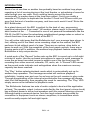
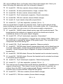
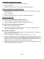
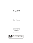
Observe the miniature LED’s provided with
your kit. Being diodes, these components are
D5
polarized and must be oriented correctly.
Examine one of the LED’s and notice how one
lead is longer than the other. The longer of the
two leads is the anode, or (+) connection. Most (+)
diodes also have a flat molded in the
component body. This corresponds to the
(-)
cathode or (-) side of the part.
D6
Leave these leads
as long as possible
(+)
PC Board
(-)
When the pc board is installed into the case the LEDs will be bent over and
pushed through the front panel, so be sure to keep the leads as long as
possible.
55. Install the red “Record” LED D5. (Leave the leads as long as possible)
56. Install the green “Play” LED D6.
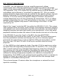
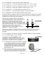
Let’s move on to the installation of the
microphone. Once installed, the case of the
microphone cartridge is at electrical ground so
extra care is needed with this installation.
57. Bend the two leads of the MIC1 cartridge
as per diagram taking care that the leads do
not touch the chrome case of the cartridge.
Keep the leads as long as possible as the
cartridge will sit up off the circuit board by
approximately 1/8”.
58. To ease the mounting of the microphone,
first melt a bit of solder onto the two solder
pads on the board. Now the cartridge can be
BS-1 • 15
installed by reheating each solder pad while holding the cartridge in place.
Once installed, you may want to touch-up each joint with a bit more solder
to ensure a solid connection.
59. Check once again to be sure that the two leads do not touch the outer
chrome case of the MIC1 and also that the case does not contact the circuit
board. A short in this area will prevent the Microphone input from working.
60. Install R12, 10K ohm potentiometer (marked 10K). Solder all five points.
If everything looks good, it’s time to install the three remaining parts.
61. Carefully insert the voice recorder IC U2 into the socket, taking care
that ALL 28 pins get into their proper holes. The orientation of the notched
end, as shown on the Parts Layout Diagram is critically important.
62. Install the microprocessor U4 into the socket. This is the 16 pin IC with
the sticker. Once again, check for proper orientation of the notched end.
Double check all pins to make sure none are bent under. A little time spent
here can save a lot of grief later!
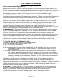
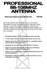
63. You should still have one 10K ohm
resistor left. This is to be soldered on the
bottom side of the PC board, from pin 23 of
10K
U2 to the positive side of C2. Follow the
diagram for correct placement.
That’s it! All components should be installed.
Before applying power it would be a good idea
for one last glance over the entire pc board.
Check for:
•
Missed solder joints.
•
Solder shorts between components. Check your schematic and parts layout
diagrams if you suspect a fault.
•
Proper orientation of diodes, capacitors, and ICs.
•
Ensure proper power supply polarity and voltage. (12 volts DC, center tip
positive)
INITIAL TESTING AND OPERATION
Power Supply Considerations
The BS1 is designed to run off an external source of 9 to 15 VDC. Batteries,
power supplies, or AC adapters may be connected to the unit through the
power jack, J5. Care should be taken to ensure that the center tip is positive.
Before applying power, make sure the three pushbutton switches are in the
“out” position and the volume control is turned down.
BS-1 • 16
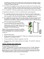
Recording
Recording is possible from either the on-board microphone or external line input. The input choice is selected by jumper position of J2. To select the Microphone input, move the jumper to the “MIC IN” position as marked on the board.
The “LINE IN” position selects recording from a Line Level input from an external source such as the Line Out of a cassette or CD player.
To record a voice message:
1. Set J2 to the “MIC IN” position.
2. Power up the unit by pushing in the power button.
3. Push the “Record” button S1. (The “Record” LED will illuminate.)***
4. Start speaking into the microphone.
5. Push the “Record” button a second time to release it and end recording.
To record from an external source:
1. Set J2 to the “LINE IN” position.
2. Connect the Line Level Output of the CD or tape player to the “Line Input”
jack J6 on the BS1. Potentiometer R2 adjusts the recording level and is typically set to about the “4 o’clock” position (as seen from looking over the
front panel.) DO NOT CONNECT SPEAKER LEVEL OUTPUTS TO THE
BS1 INPUTS OR DAMAGE TO U2 COULD RESULT!
3. Push the “Record” button on the BS1. (The “Record” LED will illuminate.)***
4. Start the playback of the CD or tape player.
5. Push the “Record” button a second time to release it and end recording.
*** If maximum memory capacity has been reached before releasing the
“Record” button, the “Record” LED will turn off indicating the unit has stopped
recording. Release the “Record” button at this time.
Recorded messages may be any length of time up to the maximum capacity of
8 minutes. Since the ISD4004 stores the recordings in a non-volatile memory,
there is no worry of losing a recording due to loss of power.
Playback
The BS1 has both a speaker level output (jack J4), for monitoring playback or
announcing to a local audience, and a set of Line Level outputs (jacks J1 and
J3) designed for connection to auxiliary equipment such as power amplifiers or
broadcast transmitters. The two Line Outputs are identical and serve only to
provide easier connections to units which require stereo (left and right) inputs.
BS-1 • 17
To playback a message into a speaker:
1. Connect a speaker to the “Speaker Out” jack J4.
2. Power up the BS1.
3. Push the “Play” button S3. (The “Play” LED will illuminate.)
To play a message into auxiliary equipment:
1. Connect the “Line Out” jacks J1 and J3 to the Line Level inputs on the desired equipment.
2. Power up the BS1.
3. Push the “Play” button S3. (The “Play” LED will illuminate.)
TROUBLESHOOTING
Won’t record from Microphone and/or Line In.
1. Check for proper positioning of jumper block on J2.
2. Check for proper adjustment of R2 if recording from Line In.
The LEDs work, but nothing else happens.
1. Make sure U2 is properly seated.
2. Check for 2 volts DC on U2 pins 18 & 27. U2 runs off a separate power
source through diodes D1, D2, and D3.
Misc. faults or problems.
1. Check for proper voltage and polarity from the power source. Center tip of
power plug should be positive.
2. Check for proper DC voltages on the circuit board. ( +2, +5, +12)
3. Loose or cold solder joints, solder splashes, etc. A good solder joint is clean
and shiny. As a rule, if you need a magnifying glass to check for a good
contact, resolder it. Check your work against the schematic and parts layout
diagrams in cases of questionable solder shorts or opens.
4. Check for proper orientation and placement of ICs, and that all pins are soldered (or fully seated if in a socket).
BS-1 • 18
The Ramsey Kit Warranty
Please read carefully BEFORE calling or writing in about your kit. Most problems can be
solved without contacting the factory.
Notice that this is not a "fine print" warranty. We want you to understand your rights and ours too!
All Ramsey kits will work if assembled properly. The very fact that your kit includes this new manual
is your assurance that a team of knowledgeable people have field-tested several "copies" of this kit
straight from the Ramsey Inventory. If you need help, please read through your manual carefully.
All information required to properly build and test your kit is contained within the pages!
1. DEFECTIVE PARTS: It's always easy to blame a part for a problem in your kit, Before you
conclude that a part may be bad, thoroughly check your work. Today's semiconductors and passive
components have reached incredibly high reliability levels, and it’s sad to say that our human
construction skills have not! But on rare occasions a sour component can slip through. All our kit
parts carry the Ramsey Electronics Warranty that they are free from defects for a full ninety (90)
days from the date of purchase. Defective parts will be replaced promptly at our expense. If you
suspect any part to be defective, please mail it to our factory for testing and replacement. Please
send only the defective part(s), not the entire kit. The part(s) MUST be returned to us in suitable
condition for testing. Please be aware that testing can usually determine if the part was truly
defective or damaged by assembly or usage. Don't be afraid of telling us that you 'blew-it', we're all
human and in most cases, replacement parts are very reasonably priced.
2. MISSING PARTS: Before assuming a part value is incorrect, check the parts listing carefully to
see if it is a critical value such as a specific coil or IC, or whether a RANGE of values is suitable
(such as "100 to 500 uF"). Often times, common sense will solve a mysterious missing part
problem. If you're missing five 10K ohm resistors and received five extra 1K resistors, you can
pretty much be assured that the '1K ohm' resistors are actually the 'missing' 10 K parts ("Hum-m-m,
I guess the 'red' band really does look orange!") Ramsey Electronics project kits are packed with
pride in the USA. If you believe we packed an incorrect part or omitted a part clearly indicated in
your assembly manual as supplied with the basic kit by Ramsey, please write or call us with
information on the part you need and proof of kit purchase.
3. FACTORY REPAIR OF ASSEMBLED KITS:
To qualify for Ramsey Electronics factory repair, kits MUST:
1. NOT be assembled with acid core solder or flux.
2. NOT be modified in any manner.
3. BE returned in fully-assembled form, not partially assembled.
4. BE accompanied by the proper repair fee. No repair will be undertaken until we have received
the MINIMUM repair fee (1/2 hour labor) of $25.00, or authorization to charge it to your
credit card account.
5. INCLUDE a description of the problem and legible return address. DO NOT send a separate
letter; include all correspondence with the unit. Please do not include your own hardware
such as non-Ramsey cabinets, knobs, cables, external battery packs and the like. Ramsey
Electronics, Inc., reserves the right to refuse repair on ANY item in which we find excessive
problems or damage due to construction methods. To assist customers in such situations,
Ramsey Electronics, Inc., reserves the right to solve their needs on a case-by-case basis.
The repair is $50.00 per hour, regardless of the cost of the kit. Please understand that our
technicians are not volunteers and that set-up, testing, diagnosis, repair and repacking and
paperwork can take nearly an hour of paid employee time on even a simple kit. Of course, if we find
that a part was defective in manufacture, there will be no charge to repair your kit (But please
realize that our technicians know the difference between a defective part and parts burned out or
damaged through improper use or assembly).
4. REFUNDS: You are given ten (10) days to examine our products. If you are not satisfied, you
may return your unassembled kit with all the parts and instructions and proof of purchase to the
factory for a full refund. The return package should be packed securely. Insurance is
recommended. Please do not cause needless delays, read all information carefully.
BS-1 • 19
Endless Loop Voice Recorder Kit
Quick Reference Page Guide
Introduction ..................................... 4
Circuit Description ............................ 5
BS-1 Parts List ................................. 6
Parts Layout Diagram ...................... 8
Assembly Procedure ........................ 9
Schematic Diagram .......................... 10
Initial Testing and Operation ............ 16
Troubleshooting ............................... 18
Warranty........................................... 19
REQUIRED TOOLS
• Soldering Iron (WLC100)
• Thin Rosin Core Solder (RTS12)
• Needle Nose Pliers (MPP4 or RTS05)
• Small Diagonal Cutters (RTS04)
ADDITIONAL SUGGESTED ITEMS
•
•
•
Helping Hands Holder for PC Board/Parts (HH3)
Technician’s Tool Kit (TK405)
Desoldering Braid (RTS08)
Price: $5.00
Ramsey Publication No. MBS1
Assembly and Instruction manual for:
RAMSEY MODEL NO. BS1
RAMSEY ELECTRONICS, INC.
590 Fishers Station Drive
Victor, New York 14564
Phone (585) 924-4560
Fax (585) 924-4555
www.ramseykits.com
BS-1 • 20
TOTAL SOLDER POINTS
200
ESTIMATED ASSEMBLY
TIME
Beginner .............. 6 hrs
Intermediate......... 3 hrs
Advanced ............. 1 hrs