1
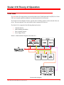
Scalar 218 Theory of Operation
Overview
The adic Scalar 218 design allows speedy fault isolation to the Field Replaceable Unit (FRU) level. Each
FRU can be rapidly replaced resulting in very short down-times for the customer.
The Scalar 218 is best thought of as three separate units: the library robotics section and each of the two
drives. The host computer views each of these units as separate SCSI devices.
The Scalar 218 is composed of the following functional sections:
l
l
l
l
Controller Section
Media Handling Mechanism
Drive Assembly Section
Power Supply Section
Below is a functional block diagram of the Scalar 218:
Functional Block Diagram
adic Service Procedure 63-1181-01 Rev A
1
Scalar 218 Theory of Operation
Functional Sections
Controller
The Controller can be logically divided into the SCSI-2 Interface and the Robotics Controller.
SCSI-2 Interface
The 218 connects to the host computer's SCSI channel through this interface. The SCSI channel is the
control, communications, and data bus through which commands, messages, and data are passed between
the Scalar, the drives, and the host computer. The SCSI-2 Interface passes commands to the Robotics
Controller from the applications software.
Robotics Controller
The multi-microprocessor-based Robotics Controller receives SCSI commands from the host computer
via the SCSI-2 Interface. The operational firmware for the Master (Main) Processor and Slave (Motion)
Processor are stored in Flash EEPROM (firmware) mounted on the main controller board. Non-volatile
RAM (NVRAM) is used to store 218 configuration information and operational logs. The Robotics
Controller controls the Media Handling Mechanism, monitors and controls the drives, and the
Operator Panel.
Embedded Control Firmware
The embedded control firmware for the 218 is divided among four processors, the Main Processor, Motion
Processor, Picker Processor, and the Micro-Stepping Motor Control (Micro-Stepper) Processor.
Main Processor
The Main Processor’s internal EPROM (Boot ROM) code provides elemental SCSI interface
intelligence, serial port control, and inter-processor communication. While executing the Boot Code, the
Main Processor checks to see if the Flash Memory contains valid operating code (operational firmware).
If the operational firmware is valid, the Main Processor signals to the Motion Processor to notify the
keyboard and then proceeds to download code from the Flash Memory to the Motion Processor’s
RAM. When completed, the Main Processor signals the Motion Processor to switch to RAM-based
code and then switches its addressing so that it begins operating out of the Flash Memory instead of it’s
internal Boot ROM.
If valid operational firmware is not found in the Flash Memory, the Main Processor continues to execute
the Boot Code, monitoring the SCSI chip for a valid request to download code to the Flash Memory.
Once executing the operational firmware in Flash Memory, the Main Processor performs the following
functions:
l
Provides complete SCSI interface protocol.
adic Service Procedure 63-1181-01 Rev A
2
Scalar 218 Theory of Operation
l
Provides a monitor function, mirroring SCSI commands and inter-processor commands via serial
port Comm 1.
l
Maintains the operational logs stored in the NVRAM.
l
Communicates commands and receives status from the Motion Processor via the interprocessor serial communication port.
Motion Processor
The Motion Processor contains code in it’s internal EPROM (Boot Code) which has elemental interprocessor communication, diagnostic LED control, and keypad I/O capability. During the boot process,
the Motion Processor communicates with the keyboard as dictated by the Main Processor. When
commanded by the Main Processor, the Motion Processor switches to operating code in it’s RAM
memory (see Main Processor description on previous page).
Once executing the code in its RAM memory, the Motion Processor performs the following functions:
l
Initializes all ports and registers.
l
Maintains position tables for the X-axis coordinates of the Media Picker assembly and relates
them to element addresses as assigned in the SCSI interface specification.
l
Monitors position by maintaining X-axis coordinate counts from the X-axis encoder interrupts.
l
Calculates position offsets for motion commands received from the Main Processor and
communicates them to the Micro-Stepper Processor.
l
Writes a binary pattern to the Diagnostic LED’s (located on the Main Controller board) associated
with currently active firmware processes.
l
Writes data to the keyboard, and LED’s. Reads switch information after an interrupt, reads door
open sensors and cartridge present sensors on a polled basis.
l
Controls and monitors the Picker Processor via one of the two serial ports.
l
Controls the Drive Mux Bus. Selects the appropriate drive assembly, monitors the assembly’s
serial stream information via the assembly’s serial multiplexer board, monitors the drive door
switch status via the Drive Mux Bus, and controls the Door Open Stepper Motor via the Drive
Mux Bus.
Picker Processor
The Picker Processor, mounted inside the Media Picker, interfaces to the Motion Processor via a
balanced differential serial port. The Picker Processor controls the following picker functions:
l
Monitors Media Picker Entry/Exit Port cartridge sensors.
l
Monitors and keeps track of the Gripper Carriage position via the three carriage optical sensors.
l
Controls the enable and direction of the gripper motor. Monitors the gripper limit signal which
indicates that the jaws have stalled or reached a limit.
l
Controls the enable, direction, and break of the roller motor.
l
Controls the enable, direction, and break of the carriage motor.
l
Controls the trigger on the Barcode reader and monitors the serial Barcode reader data.
adic Service Procedure 63-1181-01 Rev A
3
Scalar 218 Theory of Operation
Micro-Stepper Processor
The Micro-Stepper Processor takes high level movement commands and breaks them down into finite
steps of the X Stepper Motor. The four finite motor steps, are displayed on the four diagnostic LED’s.
The four digital steps are broken down further into 16 sub-steps. These sub-steps are of variable
amplitudes such that the resultant waveform of a full step approximates a sine wave. The MicroStepper Processor controls the following:
l
Quad output D to A converter.
l
Four diagnostic LED’s.
l
Data input and output registers.
Door Open Stepper Motors
Each drive assembly employs a door over the drive cartridge opening. This door must be physically opened
or closed to load or unload a cartridge. Damage to the drive and/or media will occur if the door is opened
or closed while the drive is still loaded (the tape is still wound through the read/write head mechanism). To
prevent damage to the drive and media, the drive illuminates an Operate Handle LED on its front panel to
indicate when it is unloaded (the tape is fully rewound into the cartridge). When the Operate Handle LED
is illuminated the drive assembly outputs an “OK to Open Door” status message via its serial port.
To automate the insertion and removal of cartridges the 218 employs a Door Open Stepper Motor that
rotates the door’s hinge shaft, thus opening or closing the door. This Door Open Stepper Motor is
mounted on the drive assembly’s drive mounting plate directly above the drive. The Controller Section
monitors each of the drive assembly’s serial port, via the Drive Mux Bus, and opens or closes the door
when the “OK to Open Door” status message appears.
adic Service Procedure 63-1181-01 Rev A
4
Scalar 218 Theory of Operation
Media Handling Mechanism
This section controls all movement of media within the 218. It is used to pick and place media between the
DLT drives and the 18 cartridge locations. The Media Handling Mechanism components include the
Media Picker, X Stepper Motor, X carriage, carriage rails, and associated drive belts and sensors.
Media Picker
Entry/Exit Port
The pass-through Entry/Exit Port allows the Media Picker to pick or place data cartridges from/to the
storage slots and drives without needing an additional media handling mechanism or having to rotate a
cartridge. Cartridge Sensors are mounted in both openings of the Entry/Exit Port. These sensors
monitor the position of the data cartridge. If the cartridge is not fully positioned in the Cartridge Gripper
Assembly, the Picker Processor informs the Main Processor via the Motion Processor. The
Motion Processor will prevent all movement of the Media Picker until the incorrectly positioned
cartridge is cleared.
Cartridge Gripper Assembly
The cartridge gripper assembly is an integral part of the Media Picker. The gripper is engaged by a DC
motor (Gripper Motor) which is controlled by the robotics firmware. The Gripper Motor servo control
senses torque, when a preset torque level is reached, the gripper stops.
Picker-Home Sensors
The Picker Home Sensors tells the robotics controller when the Media Picker is positioned at the
exact home position. To have a starting reference position the Media Picker must start after a reset from
the Picker-Home position (at the left side of the carriage rails). This position is determined by the PickerHome Sensor, which report its status to the robotics controller. It is the only time that the controller has
an indication of the physical position of the Media Picker. All other positions are referenced from this
point.
Barcode Reader
The Barcode Reader is used to scan barcode labels on the data cartridges located in the storage slots.
This information is passed to the application software via the SCSI bus, which stores it in its cartridge
inventory log. The barcode codes supported by the Scalar 218 are: Code 3 of 9 and Code 128.
The Barcode Reader uses a Charge Coupled Device (CCD) sensor and a Light Emitting Diode (LED)
light source. The depth of field ranges from approximately 2 inches up to 20 inches (barcode size
dependent). The red light from the LED appears as a red stripe on the barcode. The scanner is positioned
so that the light is reflected back to the CCD for reading. The Barcode Reader receives its trigger from
the Picker Processor, and outputs the scanned barcode data over the serial bus.
adic Service Procedure 63-1181-01 Rev A
5
Scalar 218 Theory of Operation
Operator Panel
The Operator Panel includes an eight-key keypad and a 4-line by 20-character scrollable LCD display.
The keypad and display provide a means for the operator to change operating parameters of the 218, such
as the SCSI ID of the robotics. Additionally, an Off-Line Diagnostics Menu is available via the Operator
Panel, through which a qualified technician can examine error, event, and operation logs, perform manual
pick and place operations, and calibrate the location of the Media Picker. The Operator Panel
interfaces to the Controller PCB.
Cartridge Sensors
Mounted beneath each of the 18 cartridge storage slots, the Cartridge Sensors monitor cartridge
presence. The contents of the 218 (inventory) can quickly be determined by polling these sensors.
Door Open Sensor
The sliding access door open sensor alerts the Motion Processor of the door's position (opened or
closed). If the door is opened during On-Line Mode operation, a SCSI UNIT ATTENTION message is
sent to the host. It is up to the software application running on the host to handle this condition with the
proper routine. If the door is opened while the 218 is performing a pick and place operation, the Motion
Processor automatically causes all Media Picker motion to stop.
Drive Assembly Section
One or two drive assemblies may be mounted in the Drive Assembly Section. The drive assemblies
respond to operating commands, and communicate directly with the host computer’s SCSI channel. Each
drive assembly receives operating voltages from the Power Supply Section of the 218. The only other
interface between an assembly and the 218 is the drive assembly multiplexer (Mux) card. The 218
monitors the drive assembly status through the Drive Mux Bus (see Door Open Stepper Motors).
Power Supply Section
The Power Supply Section contains 2 separate power supplies.
80 watt Switching Supply
The 80 watt switching supply is mounted in the Power Supply Section. It provides the operating voltages
for DLT drives 1 and 2.
50 watt Switching Supply
The 50 watt switching supply, mounted in the Power Supply Section, provides operating voltages to the
remainder of the 218.
adic Service Procedure 63-1181-01 Rev A
6