1
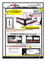
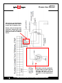
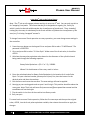
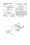
NK105G2 Plasma User Manual Techno CNC Systems, LLC ©2015 (12/2015) NCstudio Controller The Techno CNC Plasma System is powered by 220 Volt single phase power. This document will provide a quick guide to the set up and operating procedure of the Techno Plasma The CNC general stepsCutter. for cutting an NC file on the CNC plasma cutter are listed below. Review the steps below before you start the steps in this lesson on the next page and be sure to refer back to this section in you need a refresher as you complete the rest of this manual. Pre-Machining Checklist: Make sure you have all of the appropriate safety gear. (Eye protection, hearing protection, adequate ventilation, gloves, apron, fire extinguisher) Welding Jacket or Apron Minimum Shade 8 Eye Protection Chisel Confirm that you are authorized by your instructor or supervisor to operate the CNC plasma cutter. Make sure that the machine has been setup and tested and is fully operational. Make sure the torch has the correct comsumables installed for the torch’s AMP setting and the material to be cut. Make sure the CNC controller, the torch controller and air compressor are plugged in and turned on. Make sure the torch controller has the specified air pressure available. Welding Gloves Cutting an NC file with the CNC Plasma Cutter 1. Check torch consumables and air pressure. 2. Launch the Techno CNC Interface. Call: 1-631-648-7481 or Visit: support.technocnc.com 3. Position the stock. 4. Set the torch voltage and cut height. 5. Open the desired NC file. Chipping Hammer 1 NK105G2 Plasma User Manual I TABLE OF CONTENTS Forklift Guide ............................................................... Page 3 Safety Instructions ............................................................... Page 4 -5 and Cover Hypertherm to CNC Controller Wiring Diagram ........................... Page 6 1a. Techno CNC Plasma Installation ..................................... Page 7 1b. Plasma Torch Connections ..................................... Page 8 II NCStudio Controller Functionality 2.1 Control Panel Functions. ..................................... Page 9 2.2 Enabling the Machine .................................................. Page 9 2.3 Operational quick start tutorial ......................................Page 10 Single Keystroke Functions on the Handheld Pendant ........... Page 12 Shift Commands / Combination Keystrokes ........... Page 13 III Operating Tutorials 3.0 Jogging the Machine and 3.1 Changing from High/Low Jog Speed 3.2 Stepping the machine ........................ Page 14 3.3 Modifying the Jog Speed 3.4 Feedrate Override ........................ Page 15 3.5 Torch Height Control (THC) ........................ Page 16 3.6 Pierce Delay on the NC Studio controller ........................ Page 21 3.7 Adjusting the XYZ Zero position/WCS/User Origin. ........... Page 22 3.8 Loading a G-code File ........... Page 23 3.9 Running a G-code File ........... Page 24 IV V Advanced Tutorials 4.1- Alternating between Override and Programmed Feedrates .. Page 25 4.2- Setting Override speed for a G-code file................................ Page 26 4.3- Setting the Table Size ...................................... Page 27 Machine Lubrication ...................................... Page 28 VI Appendix ................................................................................... SettingsPage 29 - 35 Notes on the G-code file Acceleration Set Page 36 Changing to Different Offset (a new XY Zero location) Page 37 Using the 4th Axis on the Techno Plasma Page 38 WarrantyPage 39 2 Call: 1-631-648-7481 or Visit: support.technocnc.com NK105G2 Plasma User Manual PLASMA FORKLIFT GUIDE 1.1 I. SAFETY WARNING: DO NOT LIFT OR MOVE MACHINE USING GANTRY WARNING! DO NOT LIFT FROM FRONT OF THE MACHINE. Rear of Machine 3 4 1 2 Fig. 1.1 For safety and to prevent damage to the machine and cables, Lift Machine Using Forklift Tubes ONLY Front of Machine There are 4 Forklift Tubes on the sides of the machine. NOTE: Forklift capacity must be adequate to safely lift the machine. 2.1 II. MEASURING FORKS AND FORKLIFTING MACHINE All Techno machines are shipped assembled and secured to a wooden pallet. Left Side Fig. 2.1 Right Side Measuring the distance between the forks. (shown in Fig 2.1). 2.2 Be very careful not to damage the wiring and/ or the plumbing underneath the machine. Take care not to damage the machine. Slowly move in close to the machine. Forklift your machine up from the floor and remove the wooden pallet. Fig. 2.2 It is recommended that you have professional riggers conclude the installation if you are uncomfortable with this method. Tel: 631-648-7481 • Email: [email protected] Website: support.technocnc.com 3 Call: 1-631-648-7481 or Visit: support.technocnc.com NK105G2 Plasma User Manual i. SAFETY INFORMATION: WARNING! READ, FOLLOW AND UNDERSTAND THE TORCH MANUAL BEFORE BEGINNING USE. 1) Use a welding screen when operating Plasma Torch. 2) Wear proper eye protection. 3) Wear proper protective clothing. 4) Disconnect all power before adjusting, loading, or replacing any materials or consumables on the machine table or torch. 5) CUT MATERIAL AND MACHINE WILL REMAIN HOT FOR MANY MINUTES AFTER PLASMA TORCH HAS BEEN SHUT OFF. LET COOL ACCORDINGLY. ALWAYS USE GLOVES TO AVOID BURNS AND SHARP EDGES. 6) Disconnect all power before servicing the CNC machine or torch. The machine may have multiple power sources, disconnect all power sources. 7) Ensure proper ventilation is setup and used during operation of Plasma Torch. 8) Install Plasma Cutter on a non-flammable surface only. 9) Keep all areas around the Plasma Torch free of flammable materials, including but not limited to wood, flammable material scraps, clothing, cleaning solvents, plastic and more. 10)Keep clothing, hair, and jewelry away from the Plasma Torch and hot metals. 11)Do not operate unattended. 12)Have appropriate fire extinguishing equipment available in case of emergency. 13)Refer to MSDS for material being cut for material-specific safety instructions. Stainless steel can be particularly dangerous. 4 Call: 1-631-648-7481 or Visit: support.technocnc.com NK105G2 Plasma User Manual The Techno CNC Plasma System is powered by 220 Volt single phase power. Please make sure the CNC Plasma is properly grounded using the grounding lug provided on the rear leg of the machine. 1. Make sure the Ground Clamp (Work Lead) is connected to material being cut. Have a licensed electrician perform all electrical connections based on your electrical codes! Call: 1-631-648-7481 or Visit: support.technocnc.com 5 NK105G2 Plasma User Manual This wire is pre-wired into the Hypertherm unit and is a grey, two conductor wire. Please route it through the controller cabinet port and attach it to the left hand terminal block as shown below. This black circular connector is put inside the CNC cabinet during transport. Run it through the exit port and connect it to the Hypertherm unit 6 Call: 1-631-648-7481 or Visit: support.technocnc.com NK105G2 Plasma User Manual Ia. Techno CNC Plasma Installation 1.1 The Electronics are housed in the large controller box as shown in Figure 1.1. When unpacking the machine, avoid twisting the plastic conduit that guides the cables to the motors. 1.4 Guide the cable through the hole on the side of the enclosure and attach the hand-held controller to the DB 15 terminal. Controller box Fig. 1.1 Fig. 1.4 1.2 Open the front of the controller box (shown in Fig 1.2). Fig. 1.2 1.3 Unpack the hand-held controller and carefully attach this to the controller board. Fig. 1.3 1.5Hang the hand-held controller on the side of control box. It is now ready for use. Fig. 1.5 1.6 The terminal for the 220 volt connection is located at the bottom of the box. Fig. 1.6 Call: 1-631-648-7481 or Visit: support.technocnc.com 7 NK105G2 Plasma User Manual WARNING: Read this setup thoroughly before running the machine. Have a licensed electrician perform all electrical connections based on your local codes! Ib. Plasma Torch Connections For control connections, see schematics. When hooking up the plasma torch, be sure to use appropriate power. See Hypertherm documentation or refer to quote for details. Please read and understand the Hypertherm torch manual before operating the machine. Make sure the torch is plugged in. Both the Hypertherm torch and the plasma machine need compressed air to operate. If there is no air going to the plasma machine, you will receive an error on the handheld saying “torchalm”. You will NOT be able to move both the x and y axis until compressed air is connected to the machine. The error “torchalm” will also appear when the torch is not in its correct position. This acts as an e-stop if the torch knocks into something while in motion. Compressed air is required to operate 8 Call: 1-631-648-7481 or Visit: support.technocnc.com NK105G2 Plasma User Manual II. NC studio Controller Functionality 2.1 Control Panel Functions. Figures 2.1a and 2.1b show the buttons and their functions. Fig. 2.1a Off / On USB Port Emergency Stop Fig. 2.2b Switch can be used for fumigation (optional.) 2.2 Enabling The Machine. Pressing the green button applies power to the controller and enables the motors. (Note that the red POWER button will light up if the Emergency Stop is pressed during operation.) Fig. 2.2 Call: 1-631-648-7481 or Visit: support.technocnc.com 9 NK105G2 Plasma User Manual 2.3 Operational quick start tutorial: After all connections have been made to the CNC Plasma machine and torch, you are now ready to run a file. Step 1Turn on power to the machine and plasma torch. Step 2 You will be prompted by the hand held controller “Back to Ref. Point”. WARNING: Before answering “OK” flip the switch “Torch up”on the microstep panel to raise the torch so that it does not drag across the material when the X and Y axes home. Step 3Locating X/Y origin. Jog the machine to the desired X/Y start position by pressing the X and Y directional keys. For this example we will assume the lower left hand corner or first quadrant of the part is the origin or 0,0. Once located, press the key XY=0, and answer “OK” to “Are you sure to clear wo". The display should now show X and Y coordinate values of 0.000 Step 4 Before running a file, we want to test the torch touch off. Make sure the material is under the torch for this test and the work lead is attached to the raw stock. Press the button on the Microstep control panel “Zero Test”. The torch should lower to the material, touch off, and retract. 10 Call: 1-631-648-7481 or Visit: support.technocnc.com NK105G2 Plasma User Manual Step 5 Insert the memory stick into the port on the front of the control box. The hand held should recognize the connection and prompt you to read the stick; answer “Yes”. To load a program press Using the arrow up/down keys move to “2.USB files”; press “OK”. Again using up/down key select desired NC program you wish to run and press. The file will load into memory. Step 6Press play. The machine will automatically touch off and set the height for cutting then proceed to execute the NC program. Call: 1-631-648-7481 or Visit: support.technocnc.com 11 NK105G2 Plasma User Manual Single Keystroke Functions on the Handheld Pendant Y+ Movement (Input the number 8) Postive Feedrate Override (Input the number 7) Bold Indicates Primary Function (Parenthesis Indicates Secondary Function) Z+ Movement (Input the number 9) X- Movement (Input the number 4) X+ Movement (Input the number 6) Negative Feedrate Override (Input the number 1) (Input the number 5) Z- Movement (Input the number 3) Y- Movement (Input the number 2) Set XY Zero Position (Input a minus sign) Menu Screen (Input a decimal point) Jog Speed Select (Input the number 0) Stop Cancel Escape OK Start key Select Shift Key Yellow Keys represent movement related Switch between keys Jog and Step modes 12 Up Down Directional Directional Key Key Pause Enter Manual Parameters Screen Change high/low speed and XYZ step increment Call: 1-631-648-7481 or Visit: support.technocnc.com NK105G2 Plasma User Manual Shift Commands / Combination Keystrokes To use the shift commands, you must press and hold the shift key and then select a second key to use the Shift Command function. Increase spindle RPM Switch between work (relative) and machine (absolute) Go to home (mechanical origin) Go to current origin Decrease spindle RPM Resume from breakpoint Open help screen Call: 1-631-648-7481 or Visit: support.technocnc.com 13 NK105G2 Plasma User Manual III. Operating Tutorials. 3.0- Switching Movement to Step or Jog. There are two modes that allow the user to control the movement of the machine: Jog and Step. To switch between these modes press the “Shift” button. The mode will be displayed on the bottom left of the screen. Jog- Also known as continuous mode. When a directional arrow is pressed, the machine will move in that direction until the button is released. Stepping- Also known as step mode. When a directional arrow is pressed, the machine will move an exact amount, as dictated by the manual parameters page. To move again, you must release the button and press it again. 3.1- Jogging the machine and changing from High/Low Jog Speed. To Jog the machine, hold down one of the Yellow directional keys on the keypad while in Jog mode. The keypad has X+,X-,Y+,Y-,Z+,Z- printed on the keys to indicate direction. The machine has two speeds, High and Low. When the machine starts it will be in the Low speed. To toggle between low and high speed press the Jog Speed Select Button. You can only toggle speed when in Jog Mode. The LCD will display High or Low on the right of the screen. Select between high and low Jog speeds 3.2- Stepping the machine. To move the machine in increments, press down one of the Yellow directional keys on the keypad while in Stepping mode. The keypad has X+,X-,Y+,Y-,Z+,Z- printed on the keys to indicate direction. This will move the machine in predetermined increments in the axis selected. By default, the X and Y axes will move in .005 inches and the Z axis will move in .001 inches. 14 Call: 1-631-648-7481 or Visit: support.technocnc.com NK105G2 Plasma User Manual 3.3- Modifying the Jog Speed and Step Size The machine can be jogged at two speeds, low and high. You can also change the increments in which the machine will move in Step mode. These speeds are set in the Manual Parameters page. To access the Manual Parameters page press OK from the Main Screen Low Speed To move the cursor, use the Up and Down directional arrows. Enter a new value. Press OK to accept that value. High Speed XY Step Size Set the High and Low speed to a suitable value. Adjust the Step value as needed. To Exit out of this screen and return to the main menu press ESC. Warning: Adjust the step size carefully. If you set the step size to an excessive value, the machine will move by that value and could damage the machine. When inputting a decimal increment, you must enter the value as 0.### Zero+decimal+(your increment) 3.4- Feedrate Override. While running a G-Code file, the user can manually override the feedrate or cutting speed of the program. The range of the override goes from 10% to 120% of the original feedrate. The user can override the feedrate using the following keys: Increase Feedrate OR Decrease Feedrate Call: 1-631-648-7481 or Visit: support.technocnc.com 15 NK105G2 Plasma User Manual 3.5- Torch Height Control (THC) The Torch height is automatically controlled during processing through the microstepper THC unit shown below. Explanation of Controls: Auto/Manual: This switch controls the THC mode, auto and manual. When the switch is set for auto, the THC automatically controls the height of the torch. When the switch is set for manual, the THC operates by the users settings. The LCD screen shows the mode status. Torch up/Torch Down: This controls the Z axis movement up and down. The LCD screen shows up or down. Arc strike: This performs an arc strike test and will only work while in manual mode. When you press the button, the Hypertherm plasma power source will get an arc strike signal. The THC shows the arc voltage value and the LCD displays “ARC” is on. Zero test: This will test the position and initial height of the plasma torch, the torch will drop down, touch the material and then move to its pre-set height above the material. This can be canceled using the torch up/down switch. Sensitivity: Refers to the tolerance of the Arc Voltage setting. Recommended value of 5. Also changes values by increments of 1. Height: Arc Voltage. Also changes values by increments of 10. Up/down: Press in or twist this knob to access the main menu. Also selects different parameters inside the main menu. 16 Call: 1-631-648-7481 or Visit: support.technocnc.com NK105G2 Plasma User Manual Display: Manu: This light is on when THC is in Manual Mode or without the Auto signal from the CNC controller. Auto: This light is on when THC is in Auto Mode or when receiving the Auto signal from CNC controller. Up: This light is on when moving the torch up. Down: This light is on when moving the torch down. Lim+: This light is on when the torch is moved along the Z axis to it’s upper limit. Lim-: This light is on when the torch is moved along the Z axis to it’s lower limit. Zero: This light is on after pressing “Zero Test”. Arc: This light is on after pressing “Arc Strike”. Display Parameters: ARC: Shows the actual arc voltage value after arc strike, 000 is for no arc voltage value. SetArc: User set Arc voltage value determined according to the plate thickness and cutting speed. These values can be obtained from the cut chart in the Hypertherm manual. The arc voltage value determines the torch height to the plate. The larger the value, the higher the height. In auto mode, during cutting, the arc voltage value is automatically adjusted based off cutting feedback. Sensitivity: The response speed of the automatic torch height control. The smaller the value the slower the torch height adjustment response. Call: 1-631-648-7481 or Visit: support.technocnc.com 17 NK105G2 Plasma User Manual THC Main Menu: The THC main menu is accessed by pressing in or twisting the Up/Down knob Values are adjusted by using the Sensitivity (+1) or Height (+10) knobs Press “Zero Test” button to return to main screen. Main Menu Settings: SpeedRange: Similar to Sensitivity. The larger the speed range, the slower the THC motor control. A higher value will have slower tracing speed, a value too low will cause motor shaking. Recommended value 10. EffecRange: Effective Range. This sets the upper and lower limits of the THC Arc Voltage control in Auto mode. Recommended value of 40. PierceDel: Pierce Delay. This sets the torch on delay time in milliseconds. This value is preconfigured in the NC studio controller. See 3.6 for details. Position: Also known as location height. This is the initial height in millimeters of the torch after the “Zero Test”. Recommended value of 30. Value needs to be changed with material thickness. Refer to the correct cut chart in you Hypertherm manual for this value. Equivalent: Do not change this value. Represents the Z axis distance per pulse. Compensate: Zero or One, this setting will compensate the difference between set location height and actual location height. 18 Call: 1-631-648-7481 or Visit: support.technocnc.com NK105G2 Plasma User Manual THC Sub Menu: Press and hold “Zero Test” button on the main menu to access the Sub Menu. These settings relate to the Z-axis motor control and have been preconfigured for your machine. It is recommended not to change these values. Sub Menu Settings: StartSpeed: Default speed of the THC motor. Unit: mm/min. TopSpeed: Maximum speed of the THC motor. Unit: mm/min. SpeedRate: Motor acceleration factor. The larger the value is, the longer the acceleration time. AutoHSpeed: Auto High Speed. Maximum speed during Auto mode. Will not exceed TopSpeed value. autoLSpeed: Auto Low Speed. Minimum speed during Auto mode. Will not exceed auto high speed value. Language: 0 for Chinese, 1 for English. Call: 1-631-648-7481 or Visit: support.technocnc.com 19 NK105G2 Plasma User Manual Setting the Plasma Cut Parameters: Please refer to your Hypertherm Powermax Manual’s cut chart to ensure proper settings Maximum cut speeds are the fastest speeds possible to cut material without regard to cut quality. Recommended cut speeds are a good starting point for finding the best quality cut. You will need to adjust the speeds for your application and your table to obtain the desired cut quality. 20 Call: 1-631-648-7481 or Visit: support.technocnc.com NK105G2 Plasma User Manual The cut chart on page 20 is being used as an example. It is from the Hypertherm PowerMax45 manual. It represents the cut chart for shielded consumables on Mild Steel with English Units. In this example, we will be cutting 16 Ga mild steel and we will use the recommended settings. These are merely recommended settings, you will need to adjust accordingly. We will use the cut chart from left to right. First, we will select our Arc Current. The PowerMax 45 is capable of 45 amps so we will start there. We will set the control knob on the PowerMax 45 unit to 45 amps. Next, we choose our material thickness. In this example we will be using 16 Ga. As we move from left to right, we can use and set various parameters. Torch-to-work distance is our working “Position” value. Since we are in inches, we will multiply this value by 25.4 mm/inch to get our middle “Position” value in mm. However we will use the Initial Pierce height as our actual “position” value and make sure our “EffectRange” is large enough to encompass our Torch-to-work distance. Now we will set our Pierce time delay, as shown in seconds but the setting on the THC is in milliseconds so multiply the value by 1000. Our cut speed will be 350 inches per minute. You will use this value when creating the toolpath of the part to be cut. Our SetArc value will be 116V. Use the height knob on the main screen of the THC to set this value. 3.6 - Pierce Delay on the Automatic Torch Height Control Display To change your Pierce Delay time variable, you must navigate to the sub menu of the THC by turning the up | down knob. Use the up | down knob to select Pierce Delay. Use the +1 or +10 knob to change the value. Units are in milliseconds. Call: 1-631-648-7481 or Visit: support.technocnc.com 21 NK105G2 Plasma User Manual 3.7- Adjusting the XYZ Zero position/WCS/User Origin. XYZ zero position, Working Coordinate System (WCS), and User Origin are all the same thing. Different CAM systems and users just name the concept differently. For convenience XYZ zero position will be used in the rest of this manual. XYZ zero position is the location point on a drawing in a CAD/CAM package where X,Y and Z all equal zero. Generally, XY zero is on the bottom left corner and Z zero is the top of the part. In fig 3.3a the letters are located away from the XY zero, all points representing positive integers. Fig. 3.3a In Fig 3.3b the object represents the material the letters will be cut from. The machine should be jogged to the corner of the material by using the directional arrows on the keypad. Once the machine is in location press to set XY zero. The coordinates on the controller will change to 0,0. XY zero is now set. Fig.3.3b 22 Call: 1-631-648-7481 or Visit: support.technocnc.com NK105G2 Plasma User Manual 3.8- Loading a G-code File. Press the Menu button. Select “2.USB files” to access the flash drive. Only a G-code file with an “nc” extension with show. Scroll through the files with and Select file by pressing OK. Then load the file by pressing 1. Note: Files can be copied from this USB to the controller using the “2” button Local disk space is limited! Once a file is copied locally, it can also be selected from the jog speed /step size screen Call: 1-631-648-7481 or Visit: support.technocnc.com 23 NK105G2 Plasma User Manual 3.9- Running a G-code file. Once the XYZ origin has been set as per section 3.4 and the file has been loaded as per section 3.5 the user is ready to run the G-code file. To run the G-code file simply press the start button Once the spindle has reached speed the machine will move into position to start the first cut. The file can be paused while running by pressing To resume the file press . To abort the file at any time press . Note: When the machine pauses, the spindle will stop and the Z axis will move to the Z clearance/Safe height to allow inspection of the part. If the machine is jogged off the part during a pause, it will lose its position and when the file is resumed it will start from the new position. When using multiple tools it is best to create separate files for each tool. The last file can be resumed at a breakpoint by pressing. + 24 Call: 1-631-648-7481 or Visit: support.technocnc.com NK105G2 Plasma User Manual IV. Advanced Tutorials. 4.1- Alternating between Override and Programmed Feedrates. The controller can run G-code files with speed set by the user on the keypad, override speed, or with speed set in the CAM package/G-code file, programmed speeds. To determine what speed protocol will be used, do the following: In the main screen, press menu Use the and to enter the menu screen . key to scroll the cursor and highlight 4. oper param Press OK to select. Use the and key scroll the cursor and highlight 8. ignore F code 9. ignore S code Press OK to select. Note: The F or S Option. F stands for Feed rates, and S stands for Spindle RPMS. Note: “No” means speed in the G-code file will be obeyed. “Yes” means speed will be overrode by the controller. Call: 1-631-648-7481 or Visit: support.technocnc.com 25 NK105G2 Plasma User Manual 4.2 Setting the Override Speed for a G-code file. From the main screen, press Menu to access the Menu screen. Use the arrow keys to move the cursor and highlight 4. oper param Press OK to select this option and enter the Operations Parameters screen Use the arrow keys to move between each option and press enter to select the option. Press OK to edit the data and use the number keys to enter data. Press OK to save data and Cancel to exit out of the screen. Keep pressing cancel until you return to the main screen. G00 Speed is the rapid speed, or the speed the machine moves when the cutter is above the material. GXX Speed is the speed the machine moves when the cutter is in the material. This speed will vary with cutter size, material, cutter type, etc. More parameters in 5. MFR param 26 Call: 1-631-648-7481 or Visit: support.technocnc.com NK105G2 Plasma User Manual 4.3 Setting the Table Size. From the main screen, press Menu to access the Menu screen. Use the arrow keys to move the cursor and highlight 5. MFR param Press OK to select. Password: 33587550 The MFR parameters screen will now open. Use the arrow keys to move the cursor and highlight. 4. Machine stroke Press OK to select. Use the arrow keys to highlight a value, press OK to edit the value, and press OK to save it. Press Cancel when the value is highlighted to abort the edit. Use the arrow keys to scroll down the screen until the negative values are displayed. When all the edits are complete, press Cancel to exit out of this screen. Keep pressing cancel until you return to the main screen. The asterisk * on this setting indicates that the machine must be powered down and the axes homed in order for these new values to take affect. If these values are incorrect it will effect the running of the machine. If the values are too small, the machine will stall/stop when it reaches the value entered. If the value is too big, it is possible for the machine to hit the end of travel and damage could occur. Call: 1-631-648-7481 or Visit: support.technocnc.com 27 NK105G2 Plasma User Manual V. Machine Lubrication. 5.1 Lubricating the X-Y Rack and Pinion. Lubrication is important with rack and pinion gearing systems. A thin film of grease should always be present on the contacting tooth flanks to minimize metal to metal contact. 5.3 Lubricating Z Ballscrew The Z axis uses a ballscrew and ballnut instead of a Rack and Pinion. The ballnut has a nipple for applying lubrication to the mechanism. Fig 5.3a Lithium grease lubrication is recommend over oil, as the oil lubrication will flow away from tooth flanks. The grease should be applied to the rails at regular intervals, depending on the usage of the machine. Use a small brush to coat both rails on the side of the Y-axis and the single rail across the X-axis. Fig 5.1 Lubrication Point. Fig 5.3a Lithium grease is pumped into the lubrication point with the application gun provided with the machine. Fig 5.3b Fig 5.3b Fig 5.1 5.4 Recommended Lubricants. 5.2 Lubricating the X-Y-Z Rails The rail carriage bearings are sealed and protected Lithium Based Grease: with wipers. The rails should be lightly oiled to allow Alvania Grease No. 2(Shell) smooth operation. Avoid a build up of debris on the rails or Equivalent. by blowing them off with air, or wiping them down with Techno Part No. a rag. The rails do not need to be lubricated as often as H90Z00-8670T8 the rack, once a month should be sufficient. Oil: Vactra No. 2s(mobile) Fig 5.2 Tonner Oil or Equivalent. Techno Part No. H90200-LUBE002 Oil and Grease Kit: Techno Part No. H90Z00-LUBEKIT2 NOTE: AVOID A BUILD UP OF DEBRIS ON MOVING PARTS. CLEAN OFF ANY DEBRIS TO AVOID DAMAGING THE MACHINE. X Axis 28 Z Axis Y Axis Call: 1-631-648-7481 or Visit: support.technocnc.com Appendix - -Plasma Control Settings NK105G2 Call: 1-631-648-7481 or Visit: support.technocnc.com Plasma User Manual Plasma Control Settings Appendix Plasma Control Settings High/Low Speeds and Step Distances (from main screen, press ‘OK’) MSpd: 800 / 100 Step XY: 0.005 Step Z: 0.005 File: (active file name) Note: These numbers can vary. All following settings can be found by pressing the ‘Menu’ key and are worded/abbreviated as you would see them on screen. Note: All settings with ‘*’ on screen requires reboot to take effect. 1. LOCAL FILES 2. USB FILES 3. OPERATIONS 1. Back to REF Point 1. All Home 2. Z Home 3. X Home 4. Y Home 2. Rect Machining 1. Params Setting Engr Depth Each Depth Tool Dia Nose Gap Height Width X Init Y Init Mode Horiz Mill EXECUTE 2. Load the Last 3. Select Line No Total: ____ StartLine: ____ EndLine:_____ EXECUTE NOW 4. Machining Info Time X: _____ Y: _____ Z: _____ 29 Call: 1-631-648-7481 or Visit: support.technocnc.com 29 NK105G2 Plasma User Manual Appendix - -Plasma Control Settings Settings (continued) Call: 1-631-648-7481 or Visit: support.technocnc.com 5. Park MCS Site 1. Park Mode Not Move To Park Site To WCS Origin 2. Park Site 1. Input Site Input Park Site X: _____ Y: _____ Z: _____ 2. Select Site Select Current Position As Park Pos by [OK] Key Return ny [ESC] Key 6. Select WCS G54 WCS G55 WCS G56 WCS Select by [OK] 4. Oper Param 1. G00 Speed 394.00 in/min 2. GXX Speed 230.00 in/min 3. Back REF First NO 4. Offset 1. Public Offest 1. X 2. Y 3. Z 2. Work Offset 1. G54 Offset 1. X 2. Y 3. Z (settings repeat through G59) 5. Cycle Process 1. Cycle Process NO 2. Cycle Times 2 3. Cycle Interval 0 ms 30 30 Call: 1-631-648-7481 or Visit: support.technocnc.com NK105G2 Plasma User Manual Appendix - -Plasma Control Settings Settings (continued) Call: 1-631-648-7481 or Visit: support.technocnc.com 6. Ignore F Code YES 7. Ignore S Code YES 8. Ratio on Manu* NO 9. DXF Params 1. 1st Point as 0* YES 2. Shape Process* NO 3. Metric Size* NO 10. ENG Params 1. Lifting Height* 0.039 2. Tool Change Tip* YES 3. Cycle Times* 1 4. Deep Hole Mode* 0 5. Retract Amount* 0.25 6. Select Tool No* YES 11. Type Para 1. Use Servo YES 2. Detect Arc YES 12. Delay Sett 1. Arc Delay 800ms 2. Torch Up Delay 1000ms 3. Torch Down Delay 2000ms 4. Torch Down Delay 1000ms 5. Open Cylin Delay 2000ms 6. Closed Cylin Delay 5000ms 31 Call: 1-631-648-7481 or Visit: support.technocnc.com 31 NK105G2 Plasma User Manual Appendix - -Plasma Control Settings Settings (continued) Call: 1-631-648-7481 or Visit: support.technocnc.com 13. Corner Cont 1. Corner Toleran 0.039 inch 2. Corner Option 0 14. Machine EFF 1. G00 Speed 394.00 in/min 2. GXX Speed 230.00 in/min 3. Back REF First NO 4. SGL Axis Acc 47.000 in/sec^2 5. Max Turn Acc 94.000 in/sec^2 6. REF Circle Radius 0.197 inch 7. REF Circle Speed 230.00 in/min 8. Corner Toleran 0.039 inch 9. Corner Option 0 10. Smoothing Time 0.024s 11. Type Para 1. Use Servo YES 2. Detect Arc YES 12. Delay Sett 1. Arc Delay 800ms 2. Torch Up Delay 1000ms 3. Torch Down Delay 2000ms 4. Torch Down Delay 1000ms 5. Open Cylin Delay 2000ms 6. Closed Cylin Delay 5000ms 32 32 Call: 1-631-648-7481 or Visit: support.technocnc.com NK105G2 Plasma User Manual Appendix - -Plasma Control Settings Settings (continued) Call: 1-631-648-7481 or Visit: support.technocnc.com 15. ENG Unit YES 5. MFR Param 1. Velocity 1. Max Angle 120.000 deg 2. Startup Speed 0.000 in/min 3. Single Axis Acc 47.000 in/sec^2 4. Max Turn Acc 94.000 in/sec^2 5. Jerk 314.961 in/sec^3 6. Short Seg Spd Lmt YES 7. SPDLMT Length 0.020 inch 8. REF Circle Radius 0.197 inch 9. REF Circle Speed 230.000 in/min 2. Axis Output Dir * X: Positive Y: Positive PASSWORD: 33587550 3. Pulse Equiv * X: 0.0033200 Y: 0.0033200 4. Machine Stroke 1. Strk Upper Lmt X: Y: varies depending on machine size 2. Strk Lower Lmt X: 0 Y: 0 5. Ref Point Set 1. RefP Speed X: 70.866 in/min 33 Call: 1-631-648-7481 or Visit: support.technocnc.com 33 NK105G2 Plasma User Manual Appendix - -Plasma Control Settings Settings (continued) Call: 1-631-648-7481 or Visit: support.technocnc.com Y: 70.866 in/min 2. RefPDir X: Negative Y: Negative 3. Retract Dist 1. X Retract Dist 0.079 inch 2. Y Retract Dist 0.079 inch 6. Y Rotary Axis 1. Y as Rotary Axis* NO 2. Rotary Y Pulse 0.006 deg/pulse 3. MM as Unit NO 4. Rev Work Radius 0.394 5. Rotary Takeoff 0.291 rad/s 6. Rotary Y Acc 6.98 rad/s^2 7. Max Rotary Vel 30 r/min 7. Backlash Set 1. Compensation on NO 2. Axis Backlash * X: 0.0 Y: 0.0 Z: 0.0 8. Enable S Algo YES 9. Arc Incriment YES 10. Forward Look Seg 50 11. Sign of BK REF YES 12. G00 Feed 100%* YES 13. Smoothing Time 34 34 Call: 1-631-648-7481 or Visit: support.technocnc.com NK105G2 Plasma User Manual Appendix - -Plasma Control Settings Settings (continued) Call: 1-631-648-7481 or Visit: support.technocnc.com 0.024s 6. Param Upkeep 1. Backup Params 2. Restore Params 3. Factory Params 4. Export Params 5. Import Params 7. System Upkeep 1. Language 1. Chinese 2. English 2. Export Log 3. System Update 4. Register 5. Help Spec: Help Message Show Delay Value: 60 Unit: S 6. Reboot 7. Exit 8. Diagnosis 1. System Info 1. Software Version 2. Card No 3. Remaining Time 4. Register Tmes 2. Port List 3. Keypress Diag 4. Import Diag 5. Outport Diag 35 Call: 1-631-648-7481 or Visit: support.technocnc.com 35 NK105G2 Plasma User Manual Notes On the G-code File If a part requires multiple tools, it is best to output a different file for each part. If the G-code file references a tool number higher than T10, then the controller will give an error at the start of the file. M6 T1 to M6 T10 are allowed. In general it is best to remove T commands by telling the CAM package that the machine is not a tool changer machine, or insuring that the Tool number does not exceed 10. G92 is the Axis presetting command, when this command is encountered in the G-code file the XYZ zero position is set at the position the machine is in at that time. In general it is best to remove this from the G-code file, or if it is in the G-code file, make sure the machine is at the origin before you press start. The controller will recognise G54 to G59 offset commands. See the NK105 G2 manual for more details on these commands. Acceleration Set Under the menu MFR Params, there is a sub menu called Velocity. This menu controls the acceleration and cutting motion of the machine. The Defaults for these parameters are: Jerk 310 Single Axis Acc 25 Max Turn Acc 100 A low Max Turn Acc will result in arcs that move in a jerky motion or at a slow speed. 36 Call: 1-631-648-7481 or Visit: support.technocnc.com NK105G2 Plasma User Manual Press Menu Operations Select WCS WSC G54 Origin 1 G55 Origin 2 . . . Call: 1-631-648-7481 or Visit: support.technocnc.com 37 NK105G2 Plasma User Manual Using the 4th Axis on the Techno Plasma Note: The 4th axis on this stepper plasma machine is not a true 4th axis. You can only use this to do “wrapping” tool paths. This means that the file is designed as a regular, flat, 3-axis file, which is scaled so that the width matches the circumference of round stock. Then, instead of cutting flat, the rotary is substituted for the X-axis and the cut follows the circumference of the stock, as if it is being “wrapped” around it. To change from normal 3-axis operation to rotary operation, you must change some settings in the controller: 1. Press the menu button on the keypad. Go to and press OK to select “5. MFR Param”. The password is 33587550. 2. Go to and press OK to select “3. Pulse Equiv”. Make note of the X-axis value, it should be .00332. 3. Calculate the new pulse equivalent value based on the diameter of the cylindrical stock being used through the following equation: Rotary Pulse Equivalent = (25.4 * π * D) / 128000 Where D is the diameter of the rotary stock in inches. 4. Enter the calculated value for Rotary Pulse Equivalent in the location for X under Pulse Equiv. To input a decimal number, please press 0 (zero) first, then the button for the decimal point and then the numbers. 5. Exit the menu and restart the machine. The new settings will now be applied. 6. Now jog to your starting point and set your X and Y origin. This position should be above the rotary part. Note: The X-axis will most likely move at a different speed than normal and the coordinates will not look right. 7. Flip the switch in the front of the machine into Rotary mode. 8. Run your part To revert back to normal 3-axis operation, follow the first two steps and then put the original value, .00332, into the X-axis pulse equivalent variable, then reboot the machine to apply the changes. 38 Call: 1-631-648-7481 or Visit: support.technocnc.com NK105G2 Plasma User Manual www.technocnc.com Tel: 631-648-7481 (HTT06091113) 9/2015 Techno CNC Systems, LLC., Terms and Conditions For Limited Warranty and Repairs Warranty WARRANTY All Techno CNC Systems, LLC., mechanical components are warranted against manufacturer’s defects in material and workmanship for a period of one (1) year from the time of shipment from Techno CNC Systems, LLC., facilities. All Techno CNC Systems, LLC., electrical components are similarly warranted for a period of one (1) year from the time of shipment from Techno CNC Systems, LLC., facilities. Techno CNC Systems, LLC.,’s sole obligation under this warranty is limited to repairing the product or, at its option, replacing the product without additional charge, provided the item is properly returned to Techno CNC Systems, LLC., for repair as described below. The provisions of this warranty shall not apply to any product that has been subjected to tampering, abuse, improper setup or operating conditions, misuse, lack of proper maintenance, or unauthorized user adjustment. Techno CNC Systems, LLC., makes no warranty that its products are fit for any use or purpose to which they may be put by the customer, whether or not such use or purpose has been disclosed to Techno CNC Systems, LLC., in specifications or drawings previously or subsequently provided, and whether or not Techno CNC Systems, LLC.,’s products are specifically designed and/or manufactured for such a purpose. NOTE: Drive motors (servo or stepper) are considered “mechanical components”. THIS WARRANTY IS IN LIEU OF ALL OTHER WARRANTIES EXPRESSED OR IMPLIED. ALL OTHER WARRANTIES, INCLUDING, BUT NOT LIMITED TO, ANY WARRANTY OF MERCHANTABILITY OR FITNESS FOR A PARTICULAR PURPOSE, WHETHER EXPRESSED, IMPLIED, OR ARISING BY OPERATION OF LAW, TRADE USAGE, OR COURSE OF DEALING, ARE HEREBY DISCLAIMED. THERE ARE NO WARRANTIES THAT EXTEND BEYOND THE DESCRIPTION ON THE FACE HEREOF. LIMITATION OF REMEDY In no event shall Techno CNC Systems, LLC., be liable for any incidental, consequential, or special damages of any kind or nature whatsoever. Techno CNC Systems, LLC., is in no way liable for any lost profits arising from or connected to this agreement or items sold under this agreement, whether alleged to arise from breach of contract, expressed or implied warranty, or in tort, including, without limitation, negligence, failure to warn, or strict liability. RETURN PROCEDURE Before returning any equipment in or out of warranty, the customer must first obtain a return authorization number and packing instructions from Techno CNC Systems, LLC.,. No claim will be allowed nor credit given for products returned without such authorization. Proper packaging and insurance for transportation is solely the customer’s responsibility. After approval from Techno CNC Systems, LLC., the product should be returned with a statement of the problem and transportation prepaid. If, upon examination, warranted defects exist, the product will be repaired or replaced at no charge, and shipped prepaid back to the customer. Return shipment will be by common carrier (i.e., UPS). If rapid delivery is requested by customer, then such transport is at the customer’s expense. If an out-of-warranty situation exists, the customer will be notified of the repair costs immediately. At such time, the customer must issue a purchase order to cover the cost of the repair or authorize the product to be shipped back as is, at the customer’s expense. In any case, a restocking charge of 20% will be charged on all items returned to stock. FIELD SERVICE Repairs are ordinarily done at Techno CNC Systems, LLC.,’s Ronkonkoma, New York facility, where all necessary instrumentation is available. This instrumentation is difficult to transport, so field service is severely limited, and will only be supplied at Techno CNC Systems, LLC.,’s discretion. If field service is required and is performed at Techno CNC Systems, LLC.,’s sole discretion, all relevant expenses, including transportation, travel time, subsistence costs, and the prevailing cost per hour (eight hour minimum) are the responsibility of the customer. UNFORESEEN CIRCUMSTANCES Techno CNC Systems, LLC., is not liable for delay or failure to perform any obligations hereunder by reason of circumstances beyond its reasonable control. These circumstances include, but are not limited to, accidents, acts of God, strikes or labor disputes, laws, rules, or regulations of any government or government agency, fires, floods, delays or failures in delivery of carriers or suppliers, shortages of materials, and any other event beyond Techno CNC Systems, LLC.,’s control. ENTIRE AGREEMENT/GOVERNING LAW The terms and conditions contained herein shall constitute the entire agreement concerning the terms and conditions for the limited warranty described hereunder. No oral or other representations are in effect. This Agreement shall be governed in all respects by the laws of New York State. No legal action may be taken by any party more than one (1) year after the date of purchase. TECHNO CNC SYSTEMS, LLC., RESERVES THE RIGHT TO CHANGE DESIGNS, SPECIFICATIONS, PRICES, AND ANY APPLICABLE DOCUMENTATION WITHOUT PRIOR NOTICE. Call: 1-631-648-7481 or Visit: support.technocnc.com 39