1
DLTTM4000/DLTTM4500/DLTTM4700
Cartridge Tape Subsystem
Product Manual
DLTTM4000/DLTTM4500/DLTTM4700
Cartridge Tape Subsystem
Product Manual
March 10, 1996
81-60043-01
Quantum reserves the right to make changes and improvements to its products, without
incurring any obligation to incorporate such changes or improvements in units previously
sold or shipped.
You can request Quantum publications from your Quantum Sales Representative, or order
them directly from Quantum.
Publication Number: 81-60043-01
SERVICE CENTERS
Quantum Service Center
715 Sycamore Avenue
Milpitas, California 95035
Phone (408) 894-4000
Fax: (408) 894-3218
Quantum Asia-Pacific Pte. Ltd.
50 Tagore Lane #b1-04
Singapore, 2678
Phone: (65) 450-9333
Fax (65) 452-2544
DLTtape is a trademark of Quantum Corporation.
DLT is a trademark of Quantum Corporation.
Copyright 1996 by Quantum Corporation. All rights reserved. Printed in USA.
The following FCC Notice applies to the DLTTM4000 drive:
FCC NOTICE: This equipment has been tested and found to comply with the limits for a
Class A digital device, pursuant to Part 15 of the FCC rules. These limits are designed to
provide reasonable protection against harmful interference in residential installation. Any
changes or modifications made to this equipment may void the user’s authority to operate this
equipment.
This equipment generates, uses, and radiates radio frequency energy and, if not installed and
used in accordance with the instructions, may cause harmful interference to radio
communications. However, there is no guarantee that interference will not occur in a
particular installation. If this equipment does cause harmful interference to radio or television
reception, which can be determined by tuning the equipment off and on, the user is
encouraged to try to correct the interference by one or more of the following measures:
1.
Reorient or relocate the receiving antenna.
2.
Increase the separation between the equipment and receiver.
3.
Connect the equipment into an outlet on a circuit different from that to which the
receiver is connected.
4.
Consult the dealer or an experienced radio/TV technician for help. The shielded
interconnect cable shipped with the unit should not be altered or modified in any way.
The unit shipped without a shielded interconnect cable must use a shielded interconnect
cable.
The user may find the following booklet prepared by the Federal Communications
Commission helpful: How to Identify and Resolve Radio-TV Interference Problems. This
booklet is available from the U.S. Government Printing Office, Washington D.C., 20402.
Stock No. 004-00398-5.
All external I/O cables connecting to this unit need to be shielded. See the User Manual or
installation instructions for more options.
This digital apparatus does not exceed the Class B limits for radio noise emissions set out in
the radio interference regulations of the Canadian Department of Communications.
This equipment is in the 2nd Class Category (information equipment to be used in a
residential area or an adjacent area thereto) and conforms to the standards set by the
Voluntary Control Council For Interference by Data Processing Equipment and Electronic
Office Machines aimed at preventing radio interference in such residential area.
This equipment meets or exceeds requirements for safety in the U.S. (UL 1950), Canada
(CSA C22.2 N0. 950) and Europe (EN60950/IEC 950) requirements, and is certified to bear
the GS mark by TUV.
The following FCC Notice applies to the DLTTM4500 and DLTTM4700 mini-libraries:
FCC NOTICE: This equipment has been tested and found to comply with the limits for a
Class A device, pursuant to Part 15 of the FCC Rules. These limits are designed to provide
reasonable protection against harmful interference when the equipment is operated in a
commercial environment. This equipment generates, uses and can radiate radio frequency
energy and, if not installed and used in accordance with the instruction manual, may cause
harmful interference to radio communications. Any changes or modifications made to this
equipment may void the user’s authority to operate this equipment. Operation of this
equipment in a residential area may cause interference in which case the user at his own
expense will be required to take whatever measures may be required to correct the
interference. The shielded interconnect cable shipped with the unit should not be altered or
modified in any way. The unit shipped without a shielded cable must use a shielded
interconnect cable.
Warning! This is a Class A product. In a domestic environment this product may cause radio
interference in which case the user may be required to take adequate measures.
Achtung! Dieses ist ein Gerat der Funkstorgenzwertklasse A. In Wohnbereicghen konnen
bei Betrieb dieses Gerates Runfunkstorungen auftreten, in welchen Fallen der Benutzer fur
entsprechende GengenmaBnahmen verantwortlich ist.
Attention! Ceci est un produit de Classe A. Dans un environment domestique, ce produit
risque de creer des interferences radioelectriques, il appartiendra alors a l'utilisateur de
prendre les mesures specifiques appropriees.
Table of Contents
Chapter 1: Overview and Features of the DLT4000/DLT4500/DLT4700
Product
1.1 In This Chapter .............................................................................................. 1-1
1.2 Product Overview ........................................................................................... 1-1
1.3 Fast Data Transfer Rate .................................................................................. 1-2
1.4 High-Capacity................................................................................................. 1-2
1.5 Compaction .................................................................................................... 1-2
1.6 Strong Media.................................................................................................. 1-3
1.7 Compatibility.................................................................................................. 1-3
1.8 Firmware Update Capability ........................................................................... 1-3
1.9 Embedded Diagnostics.................................................................................... 1-3
Chapter 2: Installing and Configuring the DLT4000 Tabletop
2.1 In This Chapter .............................................................................................. 2-1
2.2 Prepare for the Installation.............................................................................. 2-1
2.2.1 Before You Start..................................................................................... 2-1
2.2.2 Installation Setup ................................................................................... 2-2
2.2.3 Site Setup ............................................................................................... 2-2
2.2.4 Site Guidelines ....................................................................................... 2-2
2.3 Install the Drive.............................................................................................. 2-4
2.4 Configure the DLT4000 Tabletop ................................................................... 2-5
2.4.1 Configuration Guidelines ....................................................................... 2-5
2.4.2 DISABLE PARITY Checking ................................................................ 2-5
2.4.3 Changing the SCSI ID............................................................................ 2-5
2.5 Connect the Cables ......................................................................................... 2-7
2.5.1 Examine the DLT4000 Rear Panel ......................................................... 2-7
DLT4000\DLT4500\DLT4700 Cartridge Tape Subsystem-v
Contents
2.5.2 Connect the SCSI Signal Cable .............................................................. 2-7
2.5.3 Terminate the SCSI Bus......................................................................... 2-8
2.5.4 Connect the Power Cord......................................................................... 2-8
2.6 Test the Installation ........................................................................................ 2-9
2.6.1 Run POST.............................................................................................. 2-9
2.6.2 What to Do after POST ........................................................................ 2-10
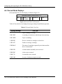
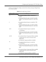
2.7 DLT4000 Troubleshooting Chart.................................................................. 2-11
Chapter 3: Configuring and Operating the DLT4000 Drive
3.1 In This Chapter .............................................................................................. 3-1
3.2 Before You Install the DLT4000 Drive ........................................................... 3-1
3.2.1 Disabling Parity Checking...................................................................... 3-2
3.2.2 Changing the SCSI ID ........................................................................... 3-5
3.2 3 Setting the TRM ENB (Single-ended only) Jumper ................................ 3-6
3.2 4 Locating the SCSI Cable and Power Connectors..................................... 3-7
3.3 Selecting Density............................................................................................ 3-8
3.4 Overview of the Front Panel ......................................................................... 3-11
3.5 Description of Controls and Indicators.......................................................... 3-12
3.5.1 Beeper.................................................................................................. 3-12
3.5.2 Unload Button...................................................................................... 3-12
3.5.3 Cartridge Insert/Release Handle ........................................................... 3-12
3.5.4 Indicator Action during Power-On Self Test and Operation.................. 3-13
3.6 Description of the Tape Cartridge................................................................. 3-17
3.6.1 Cartridge Write-Protect Switch ............................................................ 3-17
3.6.2 Data Protection .................................................................................... 3-19
3.7 Loading a Cartridge...................................................................................... 3-20
3.7.1 Tape in Use.......................................................................................... 3-22
3.8 Using the Cleaning Tape Cartridge............................................................... 3-23
3.9 Unloading a Cartridge .................................................................................. 3-24
vi-DLT4000\DLT4500\DLT4700 Cartridge Tape Subsystem
Contents
3.10 Preserving Cartridges.................................................................................. 3-26
Chapter 4: Configuring and Operating the DLT4500 Mini-Library
4.1 In This Chapter .............................................................................................. 4-1
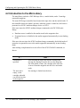
4.2 Introduction to the DLT4500 Mini-Library ..................................................... 4-2
4.3 Configure the DLT4500 Mini-Library............................................................. 4-3
4.4.1 Location of Controls, Switches, and Connectors ..................................... 4-3
4.4.2 Configuration guidelines ........................................................................ 4-7
4.4.3 SCSI ID, setting ..................................................................................... 4-7
4.4.4 Connecting the SCSI Signal Cable ......................................................... 4-8
4.5 Installation testing .......................................................................................... 4-9
4.5.1 Run POST.............................................................................................. 4-9
4.5.2 What to Do after POST .......................................................................... 4-9
4.6 Operator Control Panel ................................................................................. 4-12
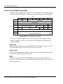
4.6.1 Normal Mode Displays......................................................................... 4-14
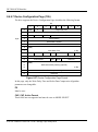
4.6.2 Density Select Mode Displays............................................................... 4-16
4.6.3 SCSI ID Select Mode............................................................................ 4-18
4.7.4 Firmware Update Mode ........................................................................ 4-19
4.8 Key lock ....................................................................................................... 4-20
4.8.1 OCP, locked or OCP, Disabled ............................................................. 4-20
4.8.2 OCP, Unlocked or Enabled................................................................... 4-20
4.9 Selecting density........................................................................................... 4-21
4.9.1 Front panel, density select .................................................................... 4-21
4.9.2 Host selection, density .......................................................................... 4-23
4.9.3 Native default, density .......................................................................... 4-23
4.10 Description of the Tape Cartridge ............................................................... 4-24
4.10.1 Tape Cartridge, positioning the write-protect switch........................... 4-24
4.10.2 Data protection................................................................................... 4-25
4.11 Description of the Magazine ....................................................................... 4-26
DLT4000\DLT4500\DLT4700 Cartridge Tape Subsystem-vii
Contents
4.11.1 Insert cartridge, magazine .................................................................. 4-27
4.11.2 Removing cartridge ............................................................................ 4-29
4.11.3 Magazine, removing from mini-library............................................... 4-30
4.11.4 Magazine, installing........................................................................... 4-30
4.11.5 Selecting a Cartridge from the Magazine............................................ 4-31
4.11.6 Loading cartridge into the Drive......................................................... 4-31
4.11.7 Unloading cartridge from the drive..................................................... 4-32
4.11.8 Opening the Magazine Door............................................................... 4-32
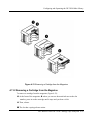
4.12 When to Use the Cleaning Tape Cartridge .................................................. 4-33
Chapter 5: Configuring and Operating the DLT4700 Mini-Library
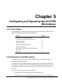
5.1 In This Chapter .............................................................................................. 5-1
5.2 Introduction to the Mini-Library..................................................................... 5-1
5.3 Configuring the DLT4700 Mini-Library ......................................................... 5-2
5.3.1 Configuration Guidelines ....................................................................... 5-3
5.3.2 Disable Parity Checking ......................................................................... 5-3
5.3.3 Change the SCSI ID............................................................................... 5-3
5.4 Mode Select Key............................................................................................. 5-5
5.4.1 OCP Disabled Mode............................................................................... 5-5
5.4.2 Automatic Mode..................................................................................... 5-7
5.4.3 Manual Mode......................................................................................... 5-7
5.4.4 Service Mode ......................................................................................... 5-8
5.5 Selecting Density............................................................................................ 5-9
5.6 Operator Control Panel................................................................................. 5-12
5.7 Power-On Process......................................................................................... 5-16
5.8 Slot Select, Load/Unload .............................................................................. 5-18
5.8.1 Selecting a Cartridge............................................................................ 5-18
5.8.2 Loading the Cartridge .......................................................................... 5-18
5.8.3 Unloading the Cartridge....................................................................... 5-19
viii-DLT4000\DLT4500\DLT4700 Cartridge Tape Subsystem
Contents
5.8.4 Opening the Receiver ........................................................................... 5-20
5.9 Magazine...................................................................................................... 5-21
5.9.1 Inserting a Cartridge ............................................................................ 5-21
5.9.2 Removing a Cartridge from the Magazine ............................................ 5-24
5.9.3 Removing the Magazine from the Receiver........................................... 5-24
5.9.4 Installing the Magazine into the Receiver............................................. 5-24
Chapter 6: Troubleshooting Guide for the DLT4500/DLT4700 MiniLibrary
6.1 In This Chapter .............................................................................................. 6-1
6.2 Conditions Necessary for Button Operation..................................................... 6-1
6.3 Operation Failure............................................................................................ 6-3
6.4 Avoiding Basic Problems................................................................................ 6-4
6.5 DLT4500 Error Conditions............................................................................. 6-5
6.5.1 DLT4500 Magazine Error ...................................................................... 6-5
6.5.1.1 DLT4500 Clearing a Magazine Error.............................................. 6-5
6.5.2 DLT4500 Loader Error Description........................................................ 6-5
6.5.3 DLT4500 Drive Error Description.......................................................... 6-5
6.5.4 DLT4500 Controller Error Description................................................... 6-5
6.5.5 DLT4500 Unknown Error Description ................................................... 6-6
6.5.5.1 DLT4500 Clearing a Loader, Drive, Controller, or Unknown Error 6-6
6.6 DLT4700 Error Conditions............................................................................. 6-6
6.6.1 DLT4700 Magazine Fault Cases............................................................. 6-6
6.6.2 DLT4700 Loader Fault Description ........................................................ 6-8
6.7 Power Problems .............................................................................................. 6-9
Chapter 7: Firmware Update
7.1 In This Chapter .............................................................................................. 7-1
7.2 DLT4000 Firmware Update Overview ............................................................ 7-1
DLT4000\DLT4500\DLT4700 Cartridge Tape Subsystem-ix
Contents
7.2.1 Updating firmware on a Standalone System ........................................... 7-2
7.3 Creating a Firmware Update Tape .................................................................. 7-4
7.3.1 On UN*X Systems ................................................................................. 7-4
7.4 Firmware Update Procedure............................................................................ 7-6
7.4.1 Updating the Firmware on DLT4000 (Drive Only Configuration) .......... 7-6
7.4.2 Updating the Firmware on the DLT4500 (Drive and Loader
Configuration) ................................................................................................ 7-9
7.4.3 Updating the Firmware on the DLT4700 (Drive and Loader
Configuration) .............................................................................................. 7-14
Chapter 8: DLT4000 SCSI Interface
8.1 Overview ........................................................................................................ 8-1
8.2 General SCSI Bus Operations......................................................................... 8-1
8.2.1 Data Transfer ......................................................................................... 8-1
8.2.2 Initiator/Target Operations..................................................................... 8-2
8.2.3 SCSI IDs and Logical Unit Numbers (LUNs) ......................................... 8-2
8.2.4 Unit Attention Condition........................................................................ 8-3
8.2.5 Behavior Around Power-On and SCSI Bus Reset ................................... 8-3
8.2.6 Data Cache and Tape Write Interaction.................................................. 8-4
8.2.7 Other SCSI Functionality ....................................................................... 8-4
8.2.8 Bus Phases ............................................................................................. 8-4
8.2.9 ATTENTION Signal Response .............................................................. 8-4
8.2.10 STATUS phase .................................................................................... 8-5
8.2.11 BUS FREE ........................................................................................... 8-6
8.2.12 BUS PARITY ERRORS ....................................................................... 8-6
8.3 SCSI Message System..................................................................................... 8-8
8.4 Tape Drive SCSI Commands ........................................................................ 8-14
8.4.1 Control Byte - Flag and Link Bits......................................................... 8-14
8.4.2 Summary of Supported Sequential-Access Device Commands.............. 8-15
x-DLT4000\DLT4500\DLT4700 Cartridge Tape Subsystem
Contents
8.4.3 ERASE (19h) ....................................................................................... 8-16
8.4.4 INQUIRY (12h) ................................................................................... 8-17
8.4.4.1 Drive Inquiry Response................................................................. 8-18
8.4.4 2 Vendor Unique Inquiry ................................................................. 8-21
8.4.4.3 Vital Product Data Pages .............................................................. 8-23
8.4.4.4 Media Loader Inquiry Response .................................................... 8-24
8.4.5 LOAD-UNLOAD (1Bh) ....................................................................... 8-25
8.4.6 LOCATE (2Bh).................................................................................... 8-27
8.4.7 LOG SELECT (4Ch)............................................................................ 8-28
8.4.7.1 Operation of LOG SELECT .......................................................... 8-30
8.4.8 LOG SENSE (4Dh) .............................................................................. 8-34
8.4.8.1 Supported Pages Page Format ....................................................... 8-37
8.4.8.2 Read/Write Error Log SENSE Page Format (Page 2 and 3)........... 8-38
8.4.8.3 Last n Error Events Page (07h) ..................................................... 8-41
8.4.8.4 Read/Write Compression Ratio Log SENSE Page Format ............. 8-42
8.4.9 MODE SELECT (15h) ......................................................................... 8-46
8.4.9.1 MODE SELECT Parameter List ................................................... 8-47
8.4.9.2 MODE SELECT Pages ................................................................. 8-50
8.4.9.3 Read/Write Error Recovery Page (01h) ......................................... 8-51
8.4.9.4 Disconnect/Reconnect Page (02h) ................................................. 8-53
8.4.9.7 Control Mode Page (0Ah) ............................................................. 8-56
8.4.9.8 Data Compression Page (0Fh)....................................................... 8-58
8.4.9.5 Device Configuration Page (10h) .................................................. 8-60
8.4.9.6 Medium Partition Page (11h) ........................................................ 8-63
8.4.9.9 EEROM Vendor Unique Page (3Eh) ............................................. 8-64
8.4.9.10 MODE SELECT Changeable Parameters.................................... 8-70
8.4.10 MODE SENSE (1Ah /5Ah)................................................................ 8-71
8.4.10.1 MODE SENSE Parameter List.................................................... 8-74
8.4.10.2 MODE SENSE Pages.................................................................. 8-78
DLT4000\DLT4500\DLT4700 Cartridge Tape Subsystem-xi
Contents
8.4.10.3 Read/Write Error Recovery Page................................................. 8-79
8.4.10.4 Disconnect/Reconnect Page......................................................... 8-81
8.4.10.7 Control Mode Page (0Ah) ........................................................... 8-82
8.4.10.8 Data Compression Page (0Fh)..................................................... 8-84
8.4.10.5 Device Configuration Page (10h) ................................................ 8-86
8.4.10.6 Medium Partition Page (11h) ...................................................... 8-88
8.4.10.9 EEROM Vendor Unique Page (3Eh)........................................... 8-89
8.4.11 PREVENT/ALLOW MEDIUM REMOVAL (1Eh)............................. 8-90
8.4.12 READ (08h)....................................................................................... 8-91
8.4.13 READ BLOCK LIMITS (05h) ........................................................... 8-93
8.4.14 READ BUFFER (3Ch) ....................................................................... 8-94
8.4.14.1 Combined Header and Data Mode............................................... 8-95
8.4.14.2 Data Mode .................................................................................. 8-95
8.4.14.3 Descriptor Mode ......................................................................... 8-95
8.4.15 READ POSITION (34h)..................................................................... 8-97
8.4.15.1 READ POSITION Data Format .................................................. 8-98
8.4.16 RECEIVE DIAGNOSTICS RESULTS (1Ch)....................................8-100
8.4.17 RELEASE UNIT (17h) .....................................................................8-101
8.4.17.1 Medium Changer Considerations...............................................8-101
8.4.18 REQUEST SENSE (03h) ..................................................................8-102
8.4.18.1 Sense Information Format..........................................................8-103
8.4.19 RESERVE UNIT (16h) .....................................................................8-112
8.4.19.1 Medium Changer Considerations...............................................8-113
8.4.20 REWIND (01h) .................................................................................8-114
8.4.21 SEND DIAGNOSTIC (1Dh) .............................................................8-115
8.4.22 SPACE (11h) ....................................................................................8-120
8.4.23 TEST UNIT READY (00h)...............................................................8-122
8.4.23.1 Medium Changer Considerations...............................................8-122
8.4.24 VERIFY (13h) ..................................................................................8-123
xii-DLT4000\DLT4500\DLT4700 Cartridge Tape Subsystem
Contents
8.4.25 WRITE (0Ah) ................................................................................. 8-124
8.4.26 WRITE BUFFER (3Bh).................................................................... 8-126
8.4.26.1 Header and Data Mode.............................................................. 8-127
8.4.26.2 Write Data ................................................................................ 8-127
8.4.26.3 Download Microcode ................................................................ 8-127
8.4.26.4 Download Microcode and Save ................................................. 8-127
8.4.27 WRITE FILEMARKS (10h)............................................................. 8-129
8.5 Supported SCSI-2 Medium Changer Device Commands ............................. 8-131
8.5.1 INITIALIZE ELEMENT STATUS (07h) .......................................... 8-132
8.5.2 MODE SENSE/SELECT (1Ah/15h)................................................... 8-133
8.5.2.1 Device Capabilities Page (1Fh) ................................................... 8-133
8.5.2.2 Element Address Assignment Page (1Dh)................................... 8-135
8.5.2.3 Transport Geometry Parameters Page (1Eh)................................ 8-137
8.5.3 MOVE MEDIUM (A5h) .................................................................... 8-138
8.5.4 READ ELEMENT STATUS (B8h) .................................................... 8-139
8.5.4.1 Element Status Data Header........................................................ 8-140
8.5.4.2 Medium Transport Element Status Page...................................... 8-141
8.5.4.3 Storage Element Status Page....................................................... 8-142
8.5.4.4 Data Transfer Element Status Page ............................................. 8-143
Appendix A: Technical Specifications
A.1 In This Appendix.......................................................................................... A-1
A.2 Drive and Mini-library Physical Descriptions................................................ A-2
A.2.1 DLT4000 Drive Physical Descriptions .................................................. A-2
A.2.2 DLT4500 Mini-library Physical Descriptions........................................ A-4
A.2.3 DLT4700 Mini-library Physical Descriptions........................................ A-5
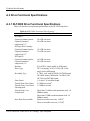
A.3 Drive Functional Description ........................................................................ A-6
A.3.1 DLT4000 Drive Functional Description................................................ A-6
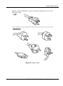
A.4 Identifying the Correct AC Power Cord......................................................... A-8
DLT4000\DLT4500\DLT4700 Cartridge Tape Subsystem-xiii
Contents
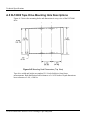
A.5 DLT4000 Tape Drive Mounting Hole Descriptions ......................................A-10
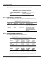
A.6 Performance Specifications ..........................................................................A-12
A.6.1 Nominal Tape Tension ........................................................................A-12
A.6.2 DLT4000 Timing Characteristics ........................................................A-12
A.6.3 DLT4500 Media Loader Timing Characteristics..................................A-13
A.6.4 DLT4700 Media Loader Timing Characteristics..................................A-13
A.7 Environmental Specifications ......................................................................A-14
A.7.1 Temperature and Humidity..................................................................A-14
A.7.2 Altitude ...............................................................................................A-15
A.8 Vibration and Shock Specifications..............................................................A-16
A.8.1 Operating Shock and Vibration ...........................................................A-16
A.8.2 Nonoperating Shock and Vibration......................................................A-17
A.9 Electromagnetic Interference (EMI) Susceptibility .......................................A-21
A.9.1 Electromagnetic Emissions..................................................................A-21
A.9.2 Conducted Emissions ..........................................................................A-22
A.9.3 Radiated Emissions .............................................................................A-22
A.9.4 Magnetic Radiated Susceptibility.........................................................A-22
A.9.5 Radiated Susceptibility ........................................................................A-23
A.9.6 Conducted Susceptibility .....................................................................A-23
A.9.7 ESD Failure Level Limits ....................................................................A-24
A.9.8 Acoustic Noise Emissions....................................................................A-24
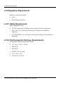
A.10 Regulatory Requirements ...........................................................................A-26
A.10.1 Safety Requirements ..........................................................................A-26
A.10.2 Electromagnetic Emission Requirements ...........................................A-26
A.11 Drive Reliability Factors ............................................................................A-27
A.12 DLTtape Recording Media Specifications ..................................................A-28
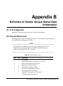
Appendix B: Definition of Vendor Unique Sense Data Information
B.1 In This Appendix...........................................................................................B-1
xiv-DLT4000\DLT4500\DLT4700 Cartridge Tape Subsystem
Contents
B.2 Internal Status................................................................................................B-1
Appendix C: Sense Key Information
C.1 In This Appendix ...........................................................................................C-1
Appendix D: EEROM Resident Bugcheck and Event Logs
D.1 EEROM Packets (Last n Error Events).......................................................... D-1
D.2 Bugcheck Packets ......................................................................................... D-2
D.3 PO/ST failure packets ................................................................................... D-4
D.4 Event Log packets......................................................................................... D-4
D.4.1 Directory Failure Event Logs ................................................................ D-5
D.5 Primary Status/Secondary Status ................................................................... D-7
D.6 Code Update (CUP) Status Packet ................................................................. D-8
DLT4000\DLT4500\DLT4700 Cartridge Tape Subsystem-xv
Contents
List of Figures
2-1 Drive Front Panel........................................................................................... 2-3
2-2 DLT4000 Rear Panel...................................................................................... 2-4
2-3 Changing the SCSI ID via the Pushbutton Switchpack ................................... 2-6
2-4 Rear Panel Components ................................................................................. 2-7
3-1 DLT4000 Drive Connectors ........................................................................... 3-3
3-2 SCSI ID Connector Pins................................................................................. 3-4
3-3 Jumper Positions ............................................................................................ 3-5
3-4 DLT4000 Jumper Setting for TRM PWR........................................................ 3-7
3-5 DLT4000 Rear Connectors............................................................................. 3-7
3-6 DLT4000 Indicators ..................................................................................... 3-11
3-7 Tape Cartridge ............................................................................................. 3-18
3-8 Loading a Cartridge ..................................................................................... 3-21
3-9 Unloading a Cartridge.................................................................................. 3-25
4-1 Front of the DLT4500 mini-library................................................................. 4-3
4-2 Mini-Library Rear Panel Components ............................................................ 4-4
4-3 Loosening the Shipping Screw ....................................................................... 4-5
4-4 Rotate the Locking Lever................................................................................ 4-6
4-5 Mini-Library Operator Control Panel ........................................................... 4-12
4-6 Normal Mode Field Definition ..................................................................... 4-14
4-8 Density Mode Field Definition ..................................................................... 4-16
4-9 Firmware Update Mode Field Definition ...................................................... 4-19
4-10 Write-Protect Switch on a Cartridge ........................................................... 4-25
4-11 DLT4500 Magazine ................................................................................... 4-26
4-12 Inserting a Cartridge into the Magazine ..................................................... 4-28
4-13 Removing a Cartridge from the Magazine .................................................. 4-29
5-1 Changing the SCSI ID via the Pushbutton Switch .......................................... 5-4
xvi-DLT4000\DLT4500\DLT4700 Cartridge Tape Subsystem
Contents
5-2 DLT4700 Operator Control Panel................................................................... 5-6
5-3 Write-Protect Switch on a Cartridge ............................................................. 5-22
5-4 Inserting a Cartridge into the Magazine........................................................ 5-23
5-5 Removing a Cartridge from the Front of the Magazine ................................. 5-25
5-6 Receiver Opened........................................................................................... 5-26
6-1 Opening the Cartridge Door to Check the Tape Leader................................... 6-4
7-1 DLT4700 Subsystem Connectors .................................................................... 7-3
7-2 Jumper Settings for TRM PWR Connector ..................................................... 7-4
8-1 Extended Message Format............................................................................ 8-10
8-2 SDTR Extended Message Format ................................................................. 8-13
8-3 ERASE CDB................................................................................................ 8-16
8-4 INQUIRY CDB ............................................................................................ 8-17
8-5 INQUIRY Response Data ............................................................................. 8-18
8-6 INQUIRY Vendor Unique Bytes Definition .................................................. 8-21
8-7 Supported Vital Product Data Pages ............................................................. 8-23
8-8 Unit Serial Number page .............................................................................. 8-23
8-9 Firmware Build Information page................................................................. 8-24
8-10 LOAD-UNLOAD CDB .............................................................................. 8-25
8-11 LOCATE CDB ........................................................................................... 8-27
8-12 LOG SELECT CDB ................................................................................... 8-28
8-13 LOG Page Control Definitions.................................................................... 8-29
8-14 Clearable Log Pages ................................................................................... 8-30
8-15 Read/Write Error Log Select Page Format .................................................. 8-31
8-16 Parameter Codes Supported ........................................................................ 8-33
8-17 LOG SENSED CDB................................................................................... 8-34
8-18 LOG Page Control Definitions.................................................................... 8-35
8-19 LOG SENSE Pages Supported.................................................................... 8-36
8-20 Supported Pages Page Format..................................................................... 8-37
8-21 Read/Write Error Log SENSE Page Format................................................ 8-38
DLT4000\DLT4500\DLT4700 Cartridge Tape Subsystem-xvii
Contents
8-22 Parameter Codes Supported........................................................................ 8-39
8-23 Threshold Met Criteria............................................................................... 8-40
8-24 Last n Error Events Page ............................................................................ 8-41
8-25 Parameter Codes Supported........................................................................ 8-42
8-26 Read/Write Compression Ratio Page Header .............................................. 8-42
8-27 Read/Write Compression Ratio LOG SENSE Page Format......................... 8-43
8-28 Read/Write Bytes Transferred LOG SENSE Page Format........................... 8-44
8-29 MODE SELECT CDB................................................................................ 8-46
8-30 MODE SELECT Parameter List................................................................. 8-47
8-31 MODE SELECT Pages Supported.............................................................. 8-50
8-32 Error Recovery Page Format....................................................................... 8-51
8-33 Disconnect/Reconnect Page Format ............................................................ 8-53
8-34 Data Transfer Disconnect Control .............................................................. 8-54
8-37 Control Mode Page (0Ah)........................................................................... 8-56
8-38 Data Compression Page.............................................................................. 8-58
8-35 Device Configuration Page Format ............................................................. 8-60
8-36 Medium Partition Page Format................................................................... 8-63
8-39 EEROM Vendor Unique Page Format ........................................................ 8-64
8-40 EEROM Vendor Unique Page Example 1................................................... 8-68
8-41 EEROM Vendor Unique Page Example 2................................................... 8-69
8-42 MODE SENSE CDB (6)............................................................................. 8-71
8-43 MODE SENSE CDB (10)........................................................................... 8-72
8-44 MODE SENSE Page Control Definition..................................................... 8-72
8-45 MODE SENSE (6) Data Header ................................................................. 8-74
8-46 MODE SENSE (10) Data Header ............................................................... 8-74
8-47 MODE SENSE Block Descriptor................................................................ 8-75
8-48 MODE SENSE Page Descriptor ................................................................. 8-75
8-49 MODE SENSE Pages Supported ................................................................ 8-78
8-50 Error Recovery Page Format....................................................................... 8-79
xviii-DLT4000\DLT4500\DLT4700 Cartridge Tape Subsystem
Contents
8-51 Disconnect/Reconnect Page Format ............................................................ 8-81
8-54 Control Mode Page (0Ah)........................................................................... 8-82
8-55 Data Compression Page (0Fh) .................................................................... 8-84
8-52 Device Configuration Page Format ............................................................. 8-86
8-53 Medium Partition Page Format ................................................................... 8-88
8-56 PREVENT/ALLOW MEDIUM REMOVAL CDB...................................... 8-90
8-57 READ CDB................................................................................................ 8-91
8-58 READ BLOCK LIMITS CDB .................................................................... 8-93
8-59 READ BLOCK LIMITS ............................................................................. 8-93
8-60 READ BUFFER CDB................................................................................. 8-94
8-61 READ BUFFER Modes Supported.............................................................. 8-94
8-62 READ BUFFER Data Head ........................................................................ 8-95
8-63 READ BUFFER Descriptor ........................................................................ 8-96
8-64 READ POSITION CDB ............................................................................. 8-97
8-65 READ POSITION Data Format.................................................................. 8-98
8-66 RECEIVE DIAGNOSTICS RESULTS CDB ............................................ 8-100
8-67 Receive Diagnostic Result Data Format .................................................... 8-100
8-68 RELEASE UNIT CDB ............................................................................. 8-101
8-69 REQUEST SENSE CDB .......................................................................... 8-102
8-70 REQUEST SENSE Data........................................................................... 8-103
8-71 RESERVE UNIT CDB ............................................................................. 8-112
8-72 RESERVE UNIT CDB ............................................................................. 8-114
8-73 SEND DIAGNOSTIC CDB...................................................................... 8-115
8-74 SEND DIAGNOSTIC Parameter List Format ........................................... 8-117
8-75 SPACE CDB ............................................................................................ 8-120
8-76 SPACE Code Definition ........................................................................... 8-120
8-77 TEST UNIT READY CDB....................................................................... 8-122
8-78 VERIFY CDB .......................................................................................... 8-123
8-79 WRITE CDB ............................................................................................ 8-124
DLT4000\DLT4500\DLT4700 Cartridge Tape Subsystem-xix
Contents
8-80 WRITE BUFFER CDB..............................................................................8-126
8-81 WRITE BUFFER Modes Supported...........................................................8-126
8-82 WRITE FILEMARKS CDB ......................................................................8-129
8-83 Initialize Element Status............................................................................8-132
8-84 Device Capabilities Page Format ...............................................................8-133
8-85 Element Address Assignment Page Format ...............................................8-135
8-86 Transport Geometry Page Format ..............................................................8-137
8-87 MOVE MEDIUM CDB.............................................................................8-138
8-88 READ ELEMENT STATUS CDB ............................................................8-139
8-89 Element Type Code Definitions .................................................................8-139
8-90 Element Status Data Header ......................................................................8-140
8-91 Medium Transport Element Status Page ....................................................8-141
8-92 Storage Element Status Page .....................................................................8-142
8-93 Data Transfer Element Status Page............................................................8-143
A-1 Power Cord ...................................................................................................A-9
A-2 Mounting Hole Dimensions (Top View) ......................................................A-10
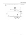
A-3 Mounting Hole Dimensions (Side View)......................................................A-11
D-1 EEROM Log Area Layout .............................................................................D-2
D-2 Bugcheck LOG Packet Layout .......................................................................D-3
D-3 POST LOG Packet Layout ............................................................................D-4
D-4 EVENT LOG Packet Layout..........................................................................D-5
D-5 Directory R/W Error Event Log Layout .........................................................D-6
D-6 Code Update (CUP) LOG Packet Layout........................................................D-9
xx-DLT4000\DLT4500\DLT4700 Cartridge Tape Subsystem
Contents
List of Tables
2-1 Adding a Terminator ...................................................................................... 2-8
2-2 POST--Right Side Indicators .......................................................................... 2-9
2-3 After POST .................................................................................................. 2-10
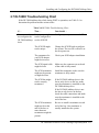
2-4 DLT4000 Troubleshooting Chart.................................................................. 2-11
3-1 Results of Density Selection.......................................................................... 3-10
3-2 Determining the Drive's Operating Condition............................................... 3-15
3-3 Before Loading the Cartridge ....................................................................... 3-19
3-4 After Loading the Cartridge and Operating .................................................. 3-19
3-5 What is Happening During Cartridge Use (Right Side Indicators) ................ 3-22
3-6 When to Use the Cleaning Cartridge ............................................................ 3-23
4-1 DLT4500 Mini-library Troubleshooting Chart.............................................. 4-10
4-2 Mini-Library Operator Control Panel............................................................ 4-13
4-3 Normal Mode, Line One Messages .............................................................. 4-14
4-4 Normal Mode, Line Two Messages............................................................... 4-15
4-5 Density Select Mode Messages ..................................................................... 4-16
4-6 Cartridge Density Display Messages............................................................. 4-17
4-7 SCSI ID SELECT Mode Display Message .................................................... 4-18
4-8 Firmware Update Mode Display Message ..................................................... 4-19
4-9 Density select mode ...................................................................................... 4-22
4-10 Cartridge, before loading ............................................................................ 4-25
4-11 After Loading the Cartridge........................................................................ 4-31
4-12 When to Use the Cleaning Cartridge........................................................... 4-33
5-1 Results of Density Selection.......................................................................... 5-11
5-2 DLT4700 Operator Control Panel................................................................. 5-12
5-3 Loader Power-On Shelf-Test......................................................................... 5-17
5-4 Load/Unload Functions................................................................................. 5-18
DLT4000\DLT4500\DLT4700 Cartridge Tape Subsystem-xxi
Contents
6-1 DLT4500 OCP Button Conditions.................................................................. 6-2
6-2 DLT4700 OCP Button Conditions.................................................................. 6-3
7-1 Block Size used for Firmware Update Tape .................................................... 7-4
7-1 Results (DLT4000) Code Update)................................................................... 7-8
7-2 Results (DLT4500) Code Update)................................................................. 7-11
7-3 Results (DLT4700) Code Update)................................................................. 7-17
8-1 Supported SCSI Messages .............................................................................. 8-8
8-2 Removing a Cartridge from the Magazine DLT4000 Supported SCSI
Commands ......................................................................................................... 8-15
8-3 Product Family Bit Values............................................................................ 8-22
8-4 EEROM Vendor Unique Page Parameters .................................................... 8-65
8-5 Changeable Mode Parameters....................................................................... 8-70
8-6 Sense Keys Used .........................................................................................8-106
8-7 Additional Sense Codes/Qualifiers Used......................................................8-107
8-8 Send Diagnostics Parameters.......................................................................8-117
8-9 Definition of Pattern Numbers Definition of Pattern Numbers .....................8-118
8-10 Sense Keys Used........................................................................................8-119
8-11 Additional Sense Codes.............................................................................8-119
8-12 Medium Changer Commands ....................................................................8-131
8-13 Medium Changer Element Addresses ........................................................8-136
A-1 DLT4000 Physical Specifications ..................................................................A-2
A-2 DLT4500 Mini-Library Physical Specifications .............................................A-4
A-3 DLT4700 Mini-Library Physical Specifications .............................................A-5
A-4 DLT4000 Functional Specifications...............................................................A-6
A-5 DLT4000 Timing Characteristics ................................................................A-12
A-6 DLT4000 Media Loader Timing Characteristics..........................................A-13
A-7 DLT4000 Media Loader Timing Characteristics..........................................A-13
A-8 Operating Ranges ........................................................................................A-14
A-9 Power-on Ranges—No Tape Loaded (Unpacked - 24 hours) ........................A-15
xxii-DLT4000\DLT4500\DLT4700 Cartridge Tape Subsystem
Contents
A-10 Storage Ranges (Unpacked or Packed) ...................................................... A-15
A-11 Shipment Ranges...................................................................................... A-15
A-12 Operating Vibration Specifications ........................................................... A-16
A-13 Operating Shock Specifications, All Products ........................................... A-16
A-14 Operating Shock Specifications, Table Tops and Drive ............................. A-17
A-15 Nonoperating Shock Overstress (Bench Handling - Unpackaged)
Specifications .................................................................................................... A-17
A-16 Nonoperating (Packaged) Vibration Specifications.................................... A-18
A-17 Nonoperating (Packaged) Repetitive Shock Specifications ........................ A-18
A-18 Nonoperating (Packaged) Shock (Drop) Specifications, All Products ........ A-19
A-19 Nonoperating (Packaged) Shock (Drop) Specifications, Table Top and
Drive ................................................................................................................. A-19
A-20 Nonoperating (Unpackaged) Vibration Specifications ............................... A-19
A-21 Nonoperating (Unpackaged) Shock Specifications .................................... A-20
A-22 Conducted Emissions................................................................................ A-22
A-23 Radiated Emissions, 30 MHz to 30 GHz ................................................... A-22
A-24 Low Frequency, Magnetic Fields, 10 to 3000 KHz .................................... A-22
A-25 High Frequency, Electric Fields, 1 to 1000 MHz ....................................... A-23
A-26 Fast Transient (Bursts) for Power and Data Cables ................................... A-23
A-27 High Energy Transient Voltage for Power Cables ..................................... A-23
A-28 Low-level Conducted Interference............................................................. A-24
A-29 ESD Failure Level Limits ......................................................................... A-24
A-30 Acoustic Noise Emissions, Nominal.......................................................... A-24
A-31 Reliability Factors..................................................................................... A-27
A-32 DLTtape Recording Media Specifications ................................................. A-28
B-1 Internal Status Code.......................................................................................B-1
B-2 Internal Status Bit Flags.................................................................................B-3
D-1 EEROM LOG Packet Types.......................................................................... D-2
D-2 Bugcheck Error Codes .................................................................................. D-3
DLT4000\DLT4500\DLT4700 Cartridge Tape Subsystem-xxiii
Contents
D-3 Event Log Codes ...........................................................................................D-5
D-4 Directory Event Log Flags .............................................................................D-7
D-5 Directory Event Status...................................................................................D-7
D-6 68020 Code Update Status...........................................................................D-10
D-7 Servo Code Update Status............................................................................D-10
xxiv-DLT4000\DLT4500\DLT4700 Cartridge Tape Subsystem
REVISION HISTORY
This Revision History provides a concise publication record of this manual. It
lists the manual revision levels, release dates, and reasons for the revisions.
Manual No.
81-108336-01
Date
5 May 95
81-108336-02
81-60043-01
Summary of Changes
Original issue
Caution added for unloading a tape
cartridge
10 Mar 96
Part Number 81-108336-02 disabled.
Manual wide, trademark, copyrights
and verbiage upgrades.
Fast Data Transfer Rate correction,
page(s) 1-2.
Figure 2-1 upgraded, page(s) 2-2.
Figure 3-6 upgraded, page(s) 3-11.
Section E added to POST testing,
page(s) 3-14.
Table 3-2, Operate Handle description
updated and label update page(s), 3-15.
Description of tape cartridge updated,
page(s) 3-17.
Loading a Cartridge, Notes added,
page(s) 3-20.
DLT4000 /DLT4500/DLT4700 Cartridge Tape Subsystem -xxv
Revision History
Manual No.
Date
Summary of Changes
Unloading a Cartridge, added
CAUTION note, page(s) 3-24.
Chapter four reconstructed.
Run POST test updated, page(s) 4-8.
Description of tape cartridge updated,
page(s) 4-20.
Figure 5-2 upgraded, page(s) 5-6.
Table 5-1 upgraded, page(s) 5-11.
Table 5-2 upgraded, page(s) 5-14.
Table 7-1 added, page(s) 7-4.
Table 7-1 consolidated, page(s) 7-8.
CAUTION message added, page(s) 7-9.
Table 8-1 modified, page(s) 8-8.
Table 8-2 modified, page(s) 8-15.
Figure 8-6 modified, page(s) 8-21.
Product Family description and table
added, page(s) 8-22.
Density Code updated, page(s) 8-49.
Table 8-3, additions and modifications,
page(s) 8-65 and 8-67.
Tables A-1, A-5, A-8, A-9, A-10, A-12,
A-16, A-17, A-20 and A30
modifications, page(s) A-3, A-11, A-13,
A-14, A-15, A-17, A-18, A-23.
Altitude modified, A-14.
xxvi-DLT4000 /DLT4500/DLT4700 Cartridge Tape Subsystem
Preface
To the Reader:
QUANTUM makes every effort to ensure the accuracy of information. However, some
errors may have been introduced inadvertently; they will be corrected in the next
release. QUANTUM recognizes that some users may require additional content. We
welcome your feedback and your suggestions for enhancements and we will evaluate
your input for a future release. Please send your comments to:
Technical Publication
Quantum Corporation
333 South Street
Shrewsbury, MA 01545
Purpose of This Manual
This manual introduces the DLTTM4000/DLTTM4500/DLTTM4700 Cartridge Tape
Subsystem and describes operating procedures, code update, and SCSI protocol
features.
All care is taken to ensure accuracy, however, some of the parameters, drawings, and
specifications being under constant review, and enhancement, may change.
Who Should Use This Manual
This manual is written for the subsystem or system integrator and users of the
DLT4000/DLT4500/DLT4700 Cartridge Tape Subsystem.
Structure of This Manual
Chapter 1, Overview and Features of the DLT4000/DLT4500/DLT4700 Product,
gives a product overview and lists the product features of the
DLT4000/DLT4500/DLT4700 cartridge tape subsystem.
DLT4000/DLT4500/DLT4700 Cartridge Tape Subsystem-xxvii
Preface
Chapter 2, Installing and Configuring the DLT4000 Tabletop Drive, describes
installing and configuring the DLT4000 tabletop tape drive.
Chapter 3, Configuring and Operating the DLT4000 Tape Drive, includes
selecting density, configuration, and other operation information for the tape drive,
such as front panel indicators and controls, Power-on Self-test, the tape cartridge
write-protect switch, loading a cartridge, using the cleaning tape, unloading a
cartridge, and preserving cartridges.
Chapter 4, Configuring and Operating the DLT4500 Mini-Library, includes
configuration, selecting density, and other operation information for the loader, such
as the power-on process, the loader Mode Select key, the operator control panel, and
functions of the Slot Select, Load/Unload, and Eject buttons.
Chapter 5, Configuring and Operating the DLT4700 Mini-Library, includes
configuration, selecting density, and other operation information for the loader, such
as the power-on process, the loader Mode Select key, the operator control panel, and
functions of the Slot Select, Load/Unload, and Eject buttons.
Chapter 6, Troubleshooting Guide for the DLT4500/DLT4700 Mini-Library,
gives instructions on how to clear failures and describes the necessary conditions to
ensure the loader OCP pushbuttons operate effectively.
Chapter 7, Firmware Update (From Tape), provides an overview on updating the
firmware, describes how to create a firmware update tape, and tells how to update the
firmware.
Chapter 8, DLT4000 SCSI Interface, details the SCSI protocol features of the
DLT4000 tape subsystem.
Appendix A, Technical Specifications, gives product specifications including
physical dimensions, performance specifications, power requirements, environmental
specifications, vibration and shock requirements, electromagnetic interference
susceptibility, regulatory requirements, and reliability factors.
Appendix B, Definition of Vendor Unique Sense Data Information, describes the
internal status codes for the DLT4000/DLT4500/DLT4700 product.
Appendix C, Sense Key Information, lists the sense key information for the
DLT4000/DLT4500/DLT4700 product.
Appendix D, EEROM Packets (Last n Error Events), describes certain error events
and error event logs.
xxviii-DLT4000/DLT4500/DLT4700 Cartridge Tape Subsystem
Chapter 1
Overview and Features of the
DLT4000/DLT4500/DLT4700 Product
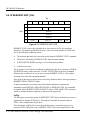
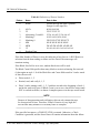
1.1 In This Chapter
Chapter 1 includes the following main topics and sections:
Topic
Section
Product Overview
Fast Data Transfer Rate
High-Capacity
Compaction
Strong Media
Compatibility
Firmware Update Capability
Embedded Diagnostics
1.2
1.3
1.4
1.5
1.6
1.7
1.8
1.9
1.2 Product Overview
The DLT4000/DLT4500/DLT4700 Cartridge Tape Subsystem is a high-performance,
high-capacity, streaming cartridge tape product designed for use on midrange and highend computing systems. Using data compression and compaction, the DLT4000 drive
features a formatted capacity of 40 GB and a sustained user data transfer rate of 3.0 MB/s.
The DLT4000 drive is a 5-1/4 inch form factor, half-inch tape drive. The design includes a
dual-channel read/write head, Lempel-Ziv (DLZ) high-efficiency data compression, and
tape mark directory to maximize data throughput and minimize data access time.
The DLT4500 Subsystem is a tape mini-library that performs automatic tape operations.
The DLT4500 mini-library includes a high-capacity tape drive and a 5-cartridge, SCSI-2
medium changer device (loader). With a typical load/unload cycle time of 20 sec., the
mini-library can provide unattended backup of 100 GB in about 11 hours.
The DLT4700 Subsystem is a tape mini-library that performs automatic tape operations.
The DLT4700 mini-library includes the tape drive and a 7-cartridge SCSI-2 medium
DLT4000/DLT4500/DLT4700 Cartridge Tape Subsystem 1-1
Overview and Features of the DLT4000/DLT4500/DLT4700 Product
changer device (loader). The mini-library provides unattended backup of 280 GB in less
than 24 hours or up to 91 GB in an 8-hour shift in a compressed mode.
The drive and mini-libraries are available in a rack mountable form factor. Also, the
DLT4000 drive, DLT4500 mini-library and DLT4700 mini-library are available with
either single-ended or differential, fast driver/receivers.
1.3 Fast Data Transfer Rate
Used for unattended backups or archiving, the DLT4000/DLT4500/DLT4700 Subsystem
allows you to back up a higher data capacity at a higher speed than earlier products. The
DLT4000/DLT4500/DLT4700 Subsystem, when operating in a non-compressed mode, has
a maximum transfer rate of 1.5 MB/s. When operating in the compressed mode, the
maximum transfer rate is 3.0 MB/s write and over 2.5 MB/s read.
1.4 High-Capacity
The DLT4000 drive accepts the new DLTtapeTM IV cartridge. When this cartridge is used
the amount of data you can store on the tape can be up to 20.0 GB native, or 40.0 GB of
data using the compression mode. The actual amount of data stored in the compression
mode is dependent on the data type. Compression can be selected on the drive front panel
or from the host by using the SCSI MODE SELECT command.
The DLT4000 drive accepts the DLTtapeTM III cartridge. When this cartridge is used the
amount of data you can store on the tape can be up to 10.0 GB native, or 20.0 GB of data
using the compression mode. The actual amount of data stored in the compression mode is
dependent on the data type. Compression can be selected on the drive front panel or from
the host by using the SCSI MODE SELECT command.
The DLT4000 drive accepts the new DLTtapeTM IIIxt cartridge. When this cartridge is
used the amount of data you can store on the tape can be up to 15.0 GB native, or 30.0 GB
of data using the compression mode. The actual amount of data stored in the compression
mode is dependent on the data type. Compression can be selected on the drive front panel
or from the host by using the SCSI MODE SELECT command.
1.5 Compaction
The compaction feature of the DLT4000 drive helps you to store data efficiently. A
read/write data cache of 2.0 MB allows working space for the compaction, enabling
maximum use of available tape space.
1-2 DLT4000/DLT4500/DLT4700 Cartridge Tape Subsystem
Overview and Features of the DLT4000/DLT4500/DLT4700 Product
1.6 Durable Media
The tape media can endure 500,000 passes and has a shelf life of 10 years, which provides
superior media durability and data reliability.
1.7 Compatibility
Quantum is committed to maintaining compatibility within the DLTTM family of tape
drives. DLT4000/DLT4500/DLT4700 Subsystem tape products are the third generation of
tape products, started with the DLTTM260, DLTTM600 and DLTTM2000 drives.
The DLT4000/DLT4500/DLT4700 Subsystem complies with the ANSI standard for SCSI2. The tape media format follows ECMA approved and ANSI proposed standards.
The DLTtape IV tape cartridge can be used in the DLT4000 drive. With this tape
cartridge, you may store up to 20.0 GB native formatted data.
The DLTtape III and DLTtape IIIxt tape cartridge can be used in the DLT4000 drive.
Using these tapes, the user may select tape densities for compatibility. The user can select
tape density on the loader or drive front panel or by using the SCSI MODE SELECT
command. The DLT4000/DLT4500/DLT4700 Subsystem can write 2.6, 6.0, 10.0 and 15.0
GB tape formats for 100% interchange compatibility with earlier drives. On a write from
BOT, the DLT4000/DLT4500/DLT4700 Subsystem reformats the cartridge recorded at
2.6, 6.0, 10.0 or 15.0 GB format to the new specified format.
1.8 Firmware Update Capability
The DLT4000 drive includes Flash EEPROM technology that allows easy on-site
installation of microcode updates from tape.
1.9 Embedded Diagnostics
The DLT4000 drive has embedded diagnostic software that tells you when head cleaning is
required, and indicates diagnostic results, and drive operating status. The drive has
embedded data logging of errors for failure analysis.
DLT4000/DLT4500/DLT4700 Cartridge Tape Subsystem 1-3
Overview and Features of the DLT4000/DLT4500/DLT4700 Product
1-4 DLT4000/DLT4500/DLT4700 Cartridge Tape Subsystem
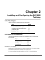
Chapter 2
Installing and Configuring the DLT4000
Tabletop
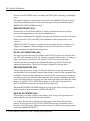
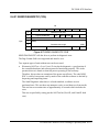
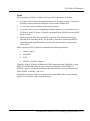
2.1 In This Chapter
Chapter 2 includes the following main topics and sections:
Topic
Section
Prepare for the Installation
Install the DLT4000 Tabletop Drive
Configure the DLT4000 Tabletop Drive
Connect the Cables
Test the Installation
DLT4000 Troubleshooting Chart
2.2
2.3
2.4
2.5
2.6
2.7
2.2 Prepare for the Installation
This section describes how to prepare for the installation of the DLT4000 tabletop
drive including:
Topic
Section
Before You Start
Installation Setup
Site Setup
Site Guidelines
2.2.1
2.2.2
2.2.3
2.2.4
2.2.1 Before You Start
Installing the DLT4000 tabletop drive requires no special tools. If you need to change
the switchpack settings on the rear panel, you will need a pen.
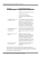
If you have problems during the installation, see Table 2-4 for troubleshooting.
DLT4000/DLT4500/DLT4700 Cartridge Tape Subsystem 2-1
Installing and Configuring the DLT4000 Tabletop Drive
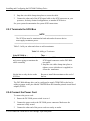
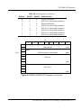
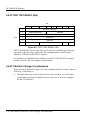
2.2.2 Installation Setup
The steps for installation setup are:
Step
1
2
3
Action
Unpack and check your shipment.
Choose a site for the DLT4000 tabletop drive.
Power off the system on which the DLT4000 tabletop drive is
to be installed.
2.2.3 Site Setup
Place the DLT4000 tabletop drive on a flat, sturdy, level area such as a desk or
tabletop.
2.2.4 Site Guidelines
Be sure to follow these guidelines for your DLT4000 tabletop drive:
•
The DLT4000 tabletop drive is designed to operate in harsh environments.
However, use care in placing the drive in an environment that is free of dust and
humidity.
2-2 DLT4000/DLT4500/DLT4700 Cartridge Tape Subsystem
Installing and Configuring the DLT4000 Tabletop Drive
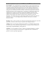
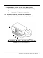
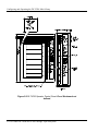
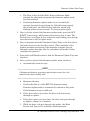
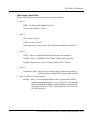
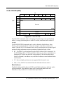
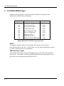
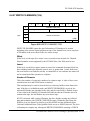
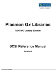
Figure 2-1 shows the DLT4000 tabletop drive.
CARTRIDGE INSERT/RELEASE HANDLE (DOWN)
Figure 2-1 Drive Front Panel
Indicators (Left Side of Drive)
Indicators (Right Side of Drive)
Density indicator 2.6 (Yellow)
Density indicator 6.0 (Yellow)
Density indicator 10.0/15.0 (Yellow)
Density indicator 20.0 (Yellow)
Compress indicator (Yellow)
Density Override indicator (Yellow)
Write Protected indicator (Orange)
Tape in Use indicator (Yellow)
Use Cleaning Tape indicator (Yellow)
Operate Handle indicator (Green)
Beeper (audible) not visible
Controls
Density Select button
Unload button
Cartridge insert/release handle
DLT4000/DLT4500/DLT4700 Cartridge Tape Subsystem 2-3
Installing and Configuring the DLT4000 Tabletop Drive
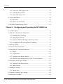
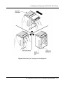
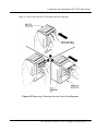
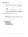
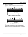
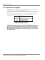
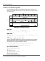
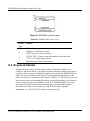
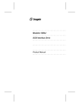
Figure 2-2 shows connector locations.
Figure 2-2 DLT4000 Rear Panel
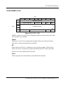
2.3 Install the Drive
To install the DLT4000 tabletop drive:
Step
1
2
3
Action
Note the DLT4000 tabletop drive factory settings.
Review Section 2.4.1.
Configure the DLT4000 tabletop drive or use on
your system:
If you need to …
Disable parity checking
Change the SCSI ID
4
Connect the cables.
2-4 DLT4000/DLT4500/DLT4700 Cartridge Tape Subsystem
See section …
2.4.2
2.4.3
Installing and Configuring the DLT4000 Tabletop Drive
2.4 Configure the DLT4000 Tabletop
This section describes how to configure the DLT4000 tabletop drive including:
Topic
Section
Configuration Guidelines
Disable Parity Checking
Changing the SCSI ID
2.4.1
2.4.2
2.4.3
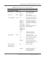
The DLT4000 tabletop drive is factory set to SCSI ID 5, unless otherwise specified.
The drive is factory set for parity generation and checking is enabled.
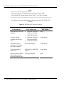
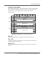
2.4.1 Configuration Guidelines
All systems use the SCSI ID to identify, or address, the DLT4000 tabletop drive.
Follow these guidelines when configuring the DLT4000 tabletop drive for use on your
system:
If you are installing the DLT4000 as …
Then …
The only SCSI device on the bus or one of
multiple SCSI devices on the bus
Be sure to use a SCSI ID that is
unique from any other device or
system ID on the SCSI bus.
The last or only device on the SCSI bus
You must terminate the bus by
installing a terminator on the drive.
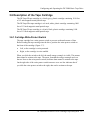
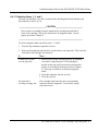
2.4.2 Disable Parity Checking
To disable parity, see your service representative.
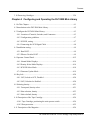
2.4.3 Changing the SCSI ID
Change the SCSI ID via the pushbutton switch on the rear of the drive. Press the
switch button(s) above or below the number display (0-7) to set the desired SCSI ID.
Press the top button to increase the number or press the bottom button to decrease the
number.
DLT4000/DLT4500/DLT4700 Cartridge Tape Subsystem 2-5
Installing and Configuring the DLT4000 Tabletop Drive
Figure 2-3 shows the SCSI ID pushbutton switch location.
Figure 2-3 Changing the SCSI ID via the Pushbutton Switch
2-6 DLT4000/DLT4500/DLT4700 Cartridge Tape Subsystem
Installing and Configuring the DLT4000 Tabletop Drive
2.5 Connect the Cables
Section 2.5 includes the following topics:
Topic
Section
Examine the DLT4000 Rear Panel
Connect the SCSI Signal Cable
Terminate the SCSI Bus
Connect the Power Cord
2.5.1
2.5.2
2.5.3
2.5.4
2.5.1 Examine the DLT4000 Rear Panel
Examine the components on the DLT4000 rear panel to complete the physical
installation (Figure 2-4).
Figure 2-4 Rear Panel Components
2.5.2 Connect the SCSI Signal Cable
To connect the SCSI signal cable:
1.
Connect one end of the SCSI cable to the leftmost SCSI signal connector on the
DLT4000 rear panel.
DLT4000/DLT4500/DLT4700 Cartridge Tape Subsystem 2-7
Installing and Configuring the DLT4000 Tabletop Drive
2.
Snap the wire cable clamps into place to secure the cable.
3.
Connect the other end of the SCSI signal cable to the SCSI connector on your
system or, for daisy-chained configurations, to another SCSI device.
See your system documentation for system SCSI connections.
2.5.3 Terminate the SCSI Bus
_________________________ NOTE ____________________________
The SCSI bus must be terminated at both ends and at least one device
must supply terminator power.
___________________________________________________________
Table 2-1 tells you when and where to add a terminator.
Table 2-1 Adding a Terminator
If the DLT4000 is …
Then …
The last or only device on the bus
and you are going to terminate the
cables externally
1. Connect the SCSI terminator to one of the
SCSI signal connectors on the DLT4000
rear panel.
2. Snap the wire cable clamps into place or
tighten screws (whichever is supplied) to
secure the terminator.
Not the last or only device on the
SCSI bus
Be sure to install the terminator at the end of
the bus.
The DLT4000 tabletop drive can be configured to supply TRM PWR on the bus by
adding a jumper to the pins labeled TRM PWR on the controller printed circuit board
adapter (PCBA).
2.5.4 Connect the Power Cord
To connect the power cord:
1.
Ensure the DLT4000 power switch is set to 0.
2.
Connect the power cord to the DLT4000 power connector. Make sure the
connector is fully seated.
3.
Connect the other end of the power cord to a nearby ac outlet.
2-8 DLT4000/DLT4500/DLT4700 Cartridge Tape Subsystem
Installing and Configuring the DLT4000 Tabletop Drive
2.6 Test the Installation
Section 2.6 includes the following topics:
Topic
Section
Run the Power-On Self-Test (POST)
What to Do after POST
2.6.1
2.6.2
2.6.1 Run POST
To test the installation for the DLT4000 tabletop drive by running POST:
1.
Turn on the system power.
2.
Set the power switch on the DLT4000 rear panel to on. POST runs automatically.
3.
Observe the indicators on the DLT4000 front panel. Ensure the indicator
sequence of events is the same as in Table 2-2 . Events on the right and left sides
happen at the same time.
Table 2-2 POST
Event
Action
1
The indicators on the right front panel turn on sequentially from
top to bottom. All indicators stay on for a few seconds.
2
All indicators on the left front panel turn on at the same time for
about three seconds and then turn off.
3
The green Operate Handle, the orange Write Protected, and the
Yellow Use Cleaning Tape indicators turn off. The yellow Tape
in Use indicator blinks while the tape drive initializes.
4
After initialization, if no cartridge is loaded, the yellow Tape In
Use indicator turns off, the green Operate Handle indicator turns
on, the handle unlatches, and the beeper sounds.
For more information on what happens after initialization when a cartridge is present,
but the handle is down; or a cartridge is present, but the handle is up (not
recommended), see Section 3.5.4 in Chapter 3.
DLT4000/DLT4500/DLT4700 Cartridge Tape Subsystem 2-9
Installing and Configuring the DLT4000 Tabletop Drive
POST completes in about 13 seconds and the drive responds normally to all
commands. However, it might take longer for the media to become ready. After a bus
reset, the tape drive responds within a bus selection time-out period.
2.6.2 What to Do after POST
Table 2-3 After POST
If …
Then …
All the events in Table 2-2 took
place
POST succeeded. Bring up the system
and run the optional system tests. See
Chapter 3 for operating the drive and
selecting density.
All left- or right-side indicators on
the DLT4000 front panel blink only
POST failed. See Table 2-4.
2-10 DLT4000/DLT4500/DLT4700 Cartridge Tape Subsystem
Installing and Configuring the DLT4000 Tabletop Drive
2.7 DLT4000 Troubleshooting Chart
If the DLT4000 tabletop drive fails during POST or operation, use Table 2-4 to
determine the problem and the action to take.
Table 2-4 DLT4000 Troubleshooting Chart
If …
Then …
You should …
Your system does
not recognize the
DLT4000 tabletop
drive
Your system might
not be configured to
see the SCSI ID
Configure your system to see the ID.
The SCSI ID might
not be unique
Change the SCSI ID and reconfigure
the system. The new ID is effective at
the next power-on.
The parameters for
your SCSI adapter
might be incorrect
Check your SCSI adapter installation.
The SCSI signal cable
might be loose
Make sure the connector on each end
of the cable is fully seated.
The SCSI terminator
might not be present
or might be loose
Install the terminator; make sure the
terminator is fully seated.
The SCSI bus might
not be correctly
terminated
If the DLT4000 tabletop drive is the
last or only device on the bus, make
sure the terminator is installed on the
DLT4000 tabletop drive.
If the DLT4000 tabletop drive is not
the last or only device on the bus,
check the cable connections and make
sure the terminator is installed at the
end of the bus.
The SCSI terminator
might not be at the
end of the bus, or
more than two
terminators might be
present
Be sure to install a terminator at each
end of the bus. One terminator is
usually installed at the system.
DLT4000/DLT4500/DLT4700 Cartridge Tape Subsystem 2-11
Installing and Configuring the DLT4000 Tabletop Drive
Table 2-4 DLT4000 Troubleshooting Chart (cont’d)
If …
Then …
You should …
Your system does
not recognize the
DLT4000 tabletop
drive
1. The SCSI bus
might be too long.
2. Too many devices
might be on the bus.
1. Limit the bus length to the ANSI
SCSI standard of 6 meters (19 feet)
for single ended (SE) or 25 meters
(82 feet) for differential.
2. Limit the number of devices on the
bus including the system) to eight.
Check your system configuration
rules.
The DLT4000
tabletop drive does
not power up
The DLT4000
tabletop drive has no
power
Check the DLT4000 power cord
connections with the DLT4000 power
switch off.
All right- or all
left-side indicators
on the DLT4000
front panel blink
A drive fault has
occurred
Try to unload the tape and reinitialize
the drive by pressing the Unload
button or turn drive power off and
then on again. The right- or left-side
indicators stop blinking and the drive
tries to reinitialize. The indicators
turn on steady again and go off if the
test succeeds.
You find fatal or
nonfatal errors for
which you cannot
determine he cause
The bus termination
or SCSI signal cable
connections might be
incorrect
Ensure the SCSI bus is terminated.
The ac power source
grounding might be
incorrect
Use an ac outlet for the DLT4000
tabletop drive on the same ac line
powering the system.
After taking the action listed in Table 2-4, power on the DLT4000 tabletop drive to
rerun POST. If all right- or left-side indicators blink again, you most likely have a
hardware failure.
2-12 DLT4000/DLT4500/DLT4700 Cartridge Tape Subsystem
Chapter 3
Configuring and Operating the DLT4000
Basic Tape Drive
3.1 In This Chapter
The configuration section in this chapter applies to the basic drive without the SCSI
ID switchpack and power supply. (Chapter 2 applies to configuring the tabletop).
Chapter 3 includes these main topics and sections:
Topic
Section
Before You Install the DLT4000 Drive
Selecting Density
Overview of the Front Panel
Description of Controls and Indicators
Description of the Tape Cartridge
Loading a Cartridge
Using the Cleaning Tape Cartridge
Unloading a Cartridge
Preserving Cartridges
3.2
3.3
3.4
3.5
3.6
3.7
3.8
3.9
3.10
3.2 Before You Install the DLT4000 Drive
Section 3.2 includes:
Topic
Section
Disabling Parity Checking
Changing the SCSI ID
Setting the TRM PWR jumpers
Locating the SCSI Cable and Power
Connectors
3.2.1
3.2.2
3.2.3
3.2.4
DLT4000/DLT4500/DLT4700 Cartridge Tape Subsystem 3-1
Configuring and Operating the DLT4000 Basic Tape Drive
3.2.1 Disabling Parity Checking
If your system does not generate parity, you can disable parity checking by adding a
jumper to the SCSI connector on the left side of the DLT4000 drive (Figure 3-1).
_________________________ NOTE ____________________________
A jumper must always be placed on the Remote ID Present position
(Figure 3-2) for the host to recognize any ID selection on this connector
using jumpers. The default ID is factory set at 5.
___________________________________________________________
3-2 DLT4000/DLT4500/DLT4700 Cartridge Tape Subsystem
Configuring and Operating the DLT4000 Basic Tape Drive
To disable parity:
1.
Use Figure 3-1, Number •, to locate the SCSI ID connector on the drive.
S CS I P arit y Disab le
F ro n t
B e ze l
TRM P WR
T R M E NB
1
R igh t s ide
F ro n t
B e z el
2
L e ft s id e
3
LK G -924 7-94 F
¶TRM PWR Connector
·SCSI ID Connector
¸Loader Connector
Figure 3-1 DLT4000 Drive Connectors
DLT4000/DLT4500/DLT4700 Cartridge Tape Subsystem 3-3
Configuring and Operating the DLT4000 Basic Tape Drive
Figure 3-2 shows what the pins on the SCSI ID connector represent.
Remote ID
Present
Disable
Parity
ID Pins
LKG-9295-94F
Figure 3-2 SCSI ID Connector Pins
_________________________ NOTE ____________________________
A jumper must always be placed on the Remote ID Present position
(Figure 3-2) for the host to recognize any ID selection on this connector.
___________________________________________________________
3-4 DLT4000/DLT4500/DLT4700 Cartridge Tape Subsystem
Configuring and Operating the DLT4000 Basic Tape Drive
2.
Place the jumper in the disable parity check position, as shown in Letter I, Figure
3-3.
8 - Bit
A
B
C
D
E
F
G
H
I
L KG-9294-94f
A. SCSI ID 0
B. SCSI ID 1
C. SCSI ID 2
D. SCSI ID 3
E. SCSI ID 4
F. SCSI ID 5
G. SCSI ID 6
H. SCSI ID 7
I. Disable parity checking.
The jumper goes in this
position with any SCSI ID
you choose.
Figure 3-3 Jumper Positions
3.2.2 Changing the SCSI ID
The drive is shipped with SCSI ID 5, unless otherwise specified. You can change the
SCSI ID by adding jumpers to the drive's SCSI connector (Figure 3-1).
DLT4000/DLT4500/DLT4700 Cartridge Tape Subsystem 3-5
Configuring and Operating the DLT4000 Basic Tape Drive
To change the SCSI ID:
1.
Use Figure 3-1, number •, to locate the SCSI ID connector on the drive.
2.
Choose a SCSI ID from 0 to 7.
3.
Use Figure 3-3, to see where to place the jumpers for the ID you choose. For
example, if you chose SCSI ID 1, place the jumpers in the same positions as those
in Letter B.
3.2.3 Setting the TRM PWR (Single-ended Only) Jumper
_________________________ NOTE ____________________________
The Small Computer System Interface (SCSI) bus must be terminated at
both ends of the bus, and at least one device must supply terminator
power.
___________________________________________________________
The DLT4000 drive does not have active termination. You can configure the
DLT4000 drive to supply termination power.
To supply terminator power for the SCSI bus:
1.
Use Figure 3-1, number Œ, to locate the TRM PWR connector on the drive.
2.
Place jumper in the positions shown in Figure 3-4, number•
3-6 DLT4000/DLT4500/DLT4700 Cartridge Tape Subsystem
Configuring and Operating the DLT4000 Basic Tape Drive
Œ
•
Figure 3-4 Jumper Settings for TRM PWR
Œ
No Term Power
•
Term Power
3.2.4 Locating the SCSI Cable and Power Connectors
To install the DLT4000 drive, note the location of the rear connectors (Figure 3-5).
Figure 3-5 DLT4000 Rear Connector
Œ
SCSI Connector
• Power Connector
Ž
Power Connector
(Custom Power Connection)
DLT4000/DLT4500/DLT4700 Cartridge Tape Subsystem 3-7
Configuring and Operating the DLT4000 Basic Tape Drive
3.3 Selecting Density
Section 3.3 describes the drive's density select features.
_________________________ CAUTION _________________________
If a prerecorded tape is used and write from beginning of tape (BOT), all
prerecorded data is lost. This includes density changes, since they only
occur when writing from BOT.
___________________________________________________________
Ways of Selecting Density
Using DLTtape IV the density defaults to 20.0 GB native. The only selection is for
compression on or off.
Using DLTtape III the density defaults to 10.0 GB native. The only selection for this
cartridge is 2.6, 6.0, 10.0 GB compression off or 20.0 GB compression on.
Using DLTtape IIIxt the density defaults to 15.0 GB native or 30.0 GB compression.
Using DLTtape IV the user can select density by any of the following operations:
1.
On all read operations and all write append operations, the recorded density is the
density to be used.
2.
On a Write from BOT, the tape density may be changed by:
•
The Density Select button. Using the Density Select button always
overrides a host selection.
•
A programmable Host Selection via your operating system. (The
Density Override indicator is off, indicating automatic or host density
selection.)
•
Native Default density 20.0 GB and Compress (assuming the Density
Select button or the host selection was not used.)
How to Select Density
To select density with the DLT4000 drive:
1.
Load the tape in the drive. The yellow Tape in Use indicator blinks while the tape
loads and calibrates.
2.
After calibration completes, Tape in Use remains lit.
3.
The indicator shows the tape's prerecorded density, such as 2.6 GB or 6.0. GB
3-8 DLT4000/DLT4500/DLT4700 Cartridge Tape Subsystem
Configuring and Operating the DLT4000 Basic Tape Drive
4.
You can use the drive's control panel at various times, not just after loading a
tape. Density selection is inactive until the write from BOT command is issued.
The controller remembers the density selection state until you do one of the
following:
•
Change the density selection
•
Unload the tape
Density Select Example
If you have loaded a tape with a prerecorded 2.6 GB density and you use the Density
Select button to select 10.0 GB density, the following should happen:
•
The 2.6 indicator remains lit—density has not changed yet and the steady light
indicates recorded tape density
•
The 10.0/15.0 indicator blinks—density change is pending
•
Density Override lights
When a write from BOT occurs, the following should happen:
•
The 2.6 indicator turns off
•
10.0/15.0 indicator is on steady
•
Density Override remains lit
DLT4000/DLT4500/DLT4700 Cartridge Tape Subsystem 3-9
Configuring and Operating the DLT4000 Basic Tape Drive
Table 3-1 shows the results of density selection.
Table 3-1 Results of Density Selection
If …
Then …
The Density Select button is not
used
The indicators show the actual density when
the tape is reading and writing. The
indicators are on steady and Density Override
is off.
The Density Select button is
used, and if the actual tape
density is the same as the density
you selected
The actual density and the Density Override
light. For example, if the actual tape density
is 10.0 GB and the selected tape density is
10.0 GB, then the indicator next to 10.0/15.0
lights.
The Density Select button is
used, and if the actual tape
density differs from the density
selected
1. The indicator with the actual density is on
steady
2. The indicator with the selected density
blinks
3. Density Override lights steady
For example, if the actual tape density is 10.0
GB and the selected density is 6.0 GB,
10.0/15.0 lights steady, 6.0 blinks, and
Density Override indicator is on steady.
To select density over the SCSI bus:
1.
Do a SCSI MODE SELECT with the density you want. For more details, see
Chapter 8.
2.
Write data to the tape from BOT.
3-10 DLT4000/DLT4500/DLT4700 Cartridge Tape Subsystem
Configuring and Operating the DLT4000 Basic Tape Drive
3.4 Overview of the Front Panel
The DLT4000 drive has the following indicators and controls for operating the drive
(Figure 3-6):
Figure 3-6 shows the DLT4000 drive indicators and controls.
CARTRIDGE INSERT/RELEASE HANDLE (DOWN)
Figure 3-6 DLT4000 Indicators
Indicators (Left Side of Drive)
Indicators (Right Side of Drive)
Density indicator 2.6 (Yellow)
Density indicator 6.0 (Yellow)
Density indicator 10.0/15.0 (Yellow)
Density indicator 20.0 (Yellow)
Compress indicator (Yellow)
Density Override indicator (Yellow)
Write Protected indicator (Orange)
Tape in Use indicator (Yellow)
Use Cleaning Tape indicator (Yellow)
Operate Handle indicator (Green)
Beeper (audible) not visible
Controls
Density Select button
Cartridge insert/release handle
Unload button
DLT4000/DLT4500/DLT4700 Cartridge Tape Subsystem 3-11
Configuring and Operating the DLT4000 Basic Tape Drive
3.5 Description of Controls and Indicators
Section 3.5 includes the following sections:
Topic
Section
Beeper
Unload Button
Cartridge Insert/Release Handle
Indicator Action during Power-on Self-test and Operation
3.5.1
3.5.2
3.5.3
3.5.4
3.5.1 Beeper
A beeper sounds when you can operate the cartridge insert/release handle. When you
hear the beep, the green Operate Handle indicator should be on.
3.5.2 Unload Button
The Unload button is used primarily to unload the tape. When the user pushes Unload,
the DLT4000 drive waits until an active write to tape is completed before beginning
the unload sequence.
The drive then rewinds the tape back into the cartridge. The tape must be completely
rewound and unloaded into the cartridge before you can remove the cartridge from the
drive. An unload operation may take 20 seconds from BOT.
If the drive is in error state (all right-side indicators are flashing on the front panel),
pushing the Unload button causes the drive to reset and unload the tape if possible.
3.5.3 Cartridge Insert/Release Handle
Operate the cartridge insert/release handle to load a cartridge or to eject a cartridge
only when the Operate Handle indicator is on, and after the momentary beep sounds.
The handle lifts to the open position and lowers to the closed position. See Section 3.7
and Section 3.9 for the operating procedures.
3-12 DLT4000/DLT4500/DLT4700 Cartridge Tape Subsystem
Configuring and Operating the DLT4000 Basic Tape Drive
3.5.4 Indicator Action during Power-On Self-Test and Operation
When you turn on system power, the drive performs the power-on self-test (POST).
The sequence of events is:
Stage
What Happens
1
The indicators on the right front panel turn on sequentially from
top to bottom. All indicators stay on for a few seconds.
2
The indicators on the left front panel turn on at the same time for
about three seconds and then turn off.
3
The green Operate Handle, the orange Write Protected, and the
yellow Use Cleaning Tape indicators turn off. The yellow Tape in
Use indicator blinks while the tape drive initializes.
4
After initialization, the drive is in one of the following four states:
DLT4000/DLT4500/DLT4700 Cartridge Tape Subsystem 3-13
Configuring and Operating the DLT4000 Basic Tape Drive
Drive State
Indicator Displays and Actions
a. No cartridge is present
1. The yellow Tape in Use indicator turns
off.
2. The green Operate Handle indicator turns
on.
3. The handle is unlatched.
4. The drive beeps momentarily.
You can now raise the handle and insert a
cartridge.
b. A cartridge is present and
the handle is down
The drive loads the cartridge. When the
yellow Tape In Use indicator stops blinking
and stays on, the tape's actual density
indicators. For example, if the actual tape
density is 2.6 GB, then the indicator turns
on next to the 2.6 label. When Density
Override blinks, you can select a density.
The drive is ready for use. (See Section 3.4.)
c. A cartridge is present, but
the handle is up (not
recommended)
The yellow Tape In Use indicator turns off.
The green Operate Handle indicator flashes.
When you lower the handle, the cartridge
loads.
d. The drive detects an error
condition
Right or left side indicators blink
repeatedly. You may try to unload the tape
and reinitialize the drive by pressing the
Unload button or turn drive power off and
then on again. The right- or left-side
indicators stop blinking and the drive tries
to reinitialize. The indicators turn on steady
again and turn off if the test succeeds.
e. The drive is powered on
with the handle open
The Operate Handle indicator is blinking;
close handle and wait for a steady
indications.
POST completes in about 15 seconds and the drive responds normally to all
commands. However, it might take longer for the media to become ready. After a bus
reset, the tape drive responds within a bus selection time-out period. Use this table to
determine the drive's operating condition:
3-14 DLT4000/DLT4500/DLT4700 Cartridge Tape Subsystem
Configuring and Operating the DLT4000 Basic Tape Drive
Table 3-2 Determining the Drive's Operating Condition
Label
Color
State
Operating Condition
Indicator (Right front panel)
Write Protected
Orange
On
Off
Tape is write-protected.
Tape is write-enabled.
Tape in Use
Yellow
Blinking
On
Tape is moving.
Tape is loaded; ready for use.
Use Cleaning Tape
Yellow
On
Drive head needs cleaning, or
the tape is bad (Section 3.8).
Remains on
after you
unload the
cleaning tape
Cleaning tape attempted to
clean the drive head, but the
tape expired, so cleaning was
not done.
After cleaning,
turns on again
when you
reload the data
cartridge
Problem data cartridge. Try
another cartridge.
Off
Cleaning is complete, or
cleaning is unnecessary.
On
Okay to operate the
cartridge/insert release handle.
Off
Do not operate the cartridge
insert/release handle.
Blinking
Close handle and wait for a
steady green indication before
inserting cartridge.
On
POST is starting.
Blinking
An error has occurred. See
Table 2-4, DLT4000
Troubleshooting Chart.
Operate Handle
All four right-side
indicators or all
left-side indicators
Green
–
DLT4000/DLT4500/DLT4700 Cartridge Tape Subsystem 3-15
Configuring and Operating the DLT4000 Basic Tape Drive
Table 3-2 Determining the Drive's Operating Condition (cont’d)
Label
Color
State
Operating Condition
On
Tape is recorded in 2.6 GB
format.
Tape is recorded in another
density. You selected this
density for a write from BOT.
Indicator (Left Front Panel)
2.6
Yellow
Blinking
6.0
Yellow
On
Blinking
10.0/15.0
Yellow
On (default)
Blinking
20.0
Yellow
On (default)
Blinking
Compress
Yellow
On
Off
Density Override
Yellow
On
Off (default)
Blinking
All four right-side
or all left-side
indicators
Blinking
Tape is recorded in 6.0 GB
format.
Tape is recorded in another
density. You selected this
density for a write from BOT.
Tape is recorded in 10.0/15.0
GB format.
Tape is recorded in another
density. You selected this
density for a write from BOT.
Tape is recorded in 20.0 GB
format.
Tape is recorded in another
density. You selected this
density for a write from BOT.
Compression mode is enabled.
(Compression can be done in
10.0/20.0 GB density only.)
Compression mode is disabled.
You selected a density from the
front panel.
Density to be selected by the
host (automatic).
You are in density selection
mode.
A POST error occurred.
3-16 DLT4000/DLT4500/DLT4700 Cartridge Tape Subsystem
Configuring and Operating the DLT4000 Basic Tape Drive
3.6 Description of the Tape Cartridge
The DLTtape III tape cartridge is a 4-inch, gray, plastic cartridge containing 1100 feet
of 1/2 inch magnetic metal particle tape.
The DLTtape IIIxt tape cartridge is a 4-inch, white, plastic cartridge containing 1800
feet of 1/2 inch magnetic metal particle tape.
The DLTtape IV tape cartridge is a 4-inch, black, plastic cartridge containing 1800
feet of 1/2 inch magnetic metal particle tape.
3.6.1 Cartridge Write-Protect Switch
The tape cartridge has a write-protect switch to prevent accidental erasure of data.
Before loading the tape cartridge into the drive, position the write-protect switch on
the front of the cartridge (Figure 3-7).
•
Left, so the cartridge is write-protected
•
Right, so the cartridge is write-enabled
When you slide the switch to the left, the small orange rectangle is visible. This means
data cannot be written to the tape. The arrow (beneath the orange rectangle and over
the two lines on the write-protect switch) indicates data cannot be written to the tape.
On the right side of the write-protect switch an arrow over one line indicates that if
you slide the write-protect switch to the right, data can be written to the tape.
DLT4000/DLT4500/DLT4700 Cartridge Tape Subsystem 3-17
Configuring and Operating the DLT4000 Basic Tape Drive
Figure 3-7 shows the write-protect switch on the tape cartridge.
Figure 3-7 Tape Cartridge
3-18 DLT4000/DLT4500/DLT4700 Cartridge Tape Subsystem
Configuring and Operating the DLT4000 Basic Tape Drive
3.6.2 Data Protection
When the cartridge write-protect switch is moved to the left, the drive turns on the
write protect LED immediately. But, if the drive is writing to the tape, write protect
does not take effect until the write completes.
Table 3-3 describes what happens to data protection when you move the write-protect
switch before loading the cartridge.
Table 3-3 Before Loading the Cartridge
If you move the write-protect switch …
Then …
To the left, the tape is write-protected; the
orange indicator on the cartridge shows
You cannot write data to the tape.
To the right, the tape is write-enabled
You can write data to the tape (if it
is not software write-protected).
Table 3-4 describes what happens to data protection when you move the write-protect
switch during operation.
Table 3-4 After Loading the Cartridge and Operating
If you move the write-protect switch …
Then …
From the write-protected position to writeenabled
The tape becomes write-enabled after
a variable amount of time (seconds).
From write-enabled to write-protected
The tape becomes write-protected
after a variable amount of time
(seconds).
DLT4000/DLT4500/DLT4700 Cartridge Tape Subsystem 3-19
Configuring and Operating the DLT4000 Basic Tape Drive
3.7 Loading a Cartridge
The following are more detailed steps for loading a cartridge (Figure 3-8):
1.
When the Operate Handle green indicator is on steady, lift the cartridge
insert/release handle open.
_________________________ NOTE ____________________________
If Operate Handle indicator is blinking, close handle and wait for a steady
green indication, then lift handle and insert tape cartridge.
___________________________________________________________
2.
Insert the cartridge.
3.
Push the cartridge into the drive.
4.
Push the handle closed.
_________________________ NOTE ____________________________
To prevent handle failures, assist the handle to the closed position. Do not
flip it.
___________________________________________________________
The green indicator turns off and the yellow indicator blinks to show the tape is
loading. When the tape is at the BOT marker, the yellow indicator turns on steady.
The tape is now ready for use.
3-20 DLT4000/DLT4500/DLT4700 Cartridge Tape Subsystem
Configuring and Operating the DLT4000 Basic Tape Drive
Figure 3-8 shows how to load a cartridge into the drive.
Figure 3-8 Loading a Cartridge
DLT4000/DLT4500/DLT4700 Cartridge Tape Subsystem 3-21
Configuring and Operating the DLT4000 Basic Tape Drive
3.7.1 Tape in Use
Whenever the yellow Tape in Use indicator is on steady, the tape is ready to use.
When the drive is calibrating, reading, writing or rewinding the tape, the Tape in Use
indicator blinks.
Use Table 3-5 to determine what is happening during cartridge use.
Table 3-5 What is Happening During Cartridge Use (Right Side Indicators)
If …
It means …
The yellow indicator is on
steady
A cartridge is loaded, but the tape is not
moving. This can mean no application is
communicating with the controller, or that
the application is communicating, but is not
delivering commands for tape motion.
The yellow indicator blinks
irregularly
A calibration read or write is in progress.
The yellow indicator blinks
regularly
The tape is loading, unloading, or
rewinding.
The green indicator turns on
and the beeper sounds
The tape is unloaded into the cartridge and
the cartridge can now be removed, or if the
drive is unloaded, a cartridge can now be
inserted.
All four indicators blink
An error has occurred during operation. See
Table 2-4, DLT4000 Troubleshooting Chart.
3-22 DLT4000/DLT4500/DLT4700 Cartridge Tape Subsystem
Configuring and Operating the DLT4000 Basic Tape Drive
3.8 Using the Cleaning Tape Cartridge
Use Table 3-6 to determine when to use the cleaning cartridge.
Table 3-6 When to Use the Cleaning Cartridge
If …
It means …
And you should …
1. Use Cleaning Tape
indicators (Figure 3-6)
The drive head needs
cleaning or the tape
is bad (see item 3)
Use the cleaning cartridge.
Follow the instructions in
Section 3.7 for loading a
cartridge into the drive. When
cleaning completes, the Use
Cleaning Tape indicator shuts
off and the beeper sounds for
you to remove the cleaning
cartridge.
2. A data cartridge
causes Use Cleaning
Tape to blink
The data cartridge
may be damaged
Back up this data onto another
cartridge. Discard the old
cartridge, which may be
damaged. A damaged cartridge
may cause unnecessary use of
the cleaning cartridge.
3. Use Cleaning Tape
still indicators after you
clean the drive head
Your data cartridge
may be causing the
problem
Try another data cartridge.
4. Use Cleaning Tape
indicators after you
load the cleaning
cartridge
Cleaning has not
been done and the
cartridge is expired
Replace the cleaning cartridge.
_________________________ NOTE ____________________________
The cleaning cartridge expires after about 20 uses.
___________________________________________________________
DLT4000/DLT4500/DLT4700 Cartridge Tape Subsystem 3-23
Configuring and Operating the DLT4000 Basic Tape Drive
3.9 Unloading a Cartridge
_________________________ CAUTION _________________________
Remove a cartridge from the drive before turning off host system power.
Failure to remove a cartridge can result in cartridge and drive damage.
When you remove the cartridge from the drive, return the cartridge to its
plastic case to prolong the cartridge life.
___________________________________________________________
To unload a cartridge from the drive (Figure 3-9):
1.
Press the Unload button (or issue the appropriate system software command). The
yellow Tape in Use indicator blinks as the tape rewinds.
2.
When the green indicator turns on (the beeper also sounds), pull the cartridge
insert/release handle open to eject the cartridge.
_________________________ CAUTION _________________________
Immediate extraction of the tape cartridge can lead to tape leader failure.
Delay tape cartridge extraction by one to two seconds to avoid this
problem.
___________________________________________________________
3.
Remove the cartridge.
4.
Push the handle closed.
3-24 DLT4000/DLT4500/DLT4700 Cartridge Tape Subsystem
Configuring and Operating the DLT4000 Basic Tape Drive
Figure 3-9 Unloading a Cartridge
DLT4000/DLT4500/DLT4700 Cartridge Tape Subsystem 3-25
Configuring and Operating the DLT4000 Basic Tape Drive
3.10 Preserving Cartridges
For longer life of recorded or unrecorded cartridges, store cartridges in a clean
environment with these conditions:
•
Do not drop or bang the cartridge. This can displace the tape leader, making the
cartridge unusable and possibly damaging the drive.
•
Keep tape cartridges out of direct sunlight and away from heaters and other heat
sources.
•
Store tape cartridges in temperatures between 10°C and 40°C (50°F to 104°F).
For longer cartridge life, always store the cartridge in its plastic container and in
room environment conditions of 72°F ±7°F (22°C ±4°C).
•
If the tape cartridge has been exposed to heat or cold extremes, stabilize the
cartridge at room temperature for the same amount of time it was exposed---up to
24 hours.
•
Do not place cartridges near electromagnetic interference sources, such as
terminals, motors, and video or X-ray equipment. Data on the tape can be altered.
•
Store tape cartridges in a dust-free environment where the relative humidity is
between 20% and 80%. For longer cartridge life, store the cartridge at 40% ±
20% relative humidity.
•
Place an identification label only in the slide-in slot on the front of the cartridge.
•
Do not adhere labels to a cartridge anywhere except in the slide-in slot.
3-26 DLT4000/DLT4500/DLT4700 Cartridge Tape Subsystem
Chapter 4
Configuring and Operating the DLT4500
Mini-Library
4.1 In This Chapter
The configuration section in this chapter applies to the mini-library and its operation.
Chapter 4 includes these main topics and sections:
Topic
Introduction to the DLT4500 Mini-Library
Configure the DLT4500 Mini-Library
Installation Test
Operator Control Panel
Key Lock
Selecting Density
Tape Cartridge Description
Magazine Description
When to Use the Cleaning Tape Cartridge
Section
4.2
4.3
4.5
4.6
4.8
4.9
4.10
4.11
4.12
DLT4000/DLT4500/DLT4700 Cartridge Tape Subsytem 4-1
Configuring and Operating the DLT4500 Mini-Library
4.2 Introduction to the Mini-Library
The mini-library includes a DLT4000 tape drive, a media loader, and a 5-cartridge
removable magazine.
The same SCSI target controller board controls the tape drive and the media loader. If
the controller detects the loader's presence when the system is turned on, the loader is
presented as a SCSI-2 medium changer device on LUN 1.
If the user issues the SCSI-2 medium changer commands to the DLT4500 minilibrary:
•
Random access is enabled to the media stored in the magazine slots
•
Sequential access is disabled to the media supported automatically in auto-loading
mode
If the user does not issue the SCSI-2 medium changer commands, the default mode of
operation is sequential access to the media supported automatically in auto-loading
mode.
Auto-loading is implemented as a side effect of the SCSI UNLOAD command, as
shown:
If …
An unload is
specified
Then …
After winding the tape back into the cartridge and
moving the cartridge from the drive to the magazine
slot from which it came, the cartridge in the next slot
is moved from the magazine into the drive and made
ready.
The next slot is
empty, or the
cartridge unloaded
was for the last slot
in the magazine
No cartridge is loaded into the drive.
4-2 DLT4000/DLT4500/DLT4700 Cartridge Tape Subsytem
. Configure and Install the DLT4500 Mini-Library
This section describes how to configure and install the mini-library including:
•
•
Connecting the SCSI signal cable to the mini-library
4 4. Location of Controls, Switches, and Connectors
Figures 4 1, -2 4- , 4 4 illustrate the front and rear panel layouts of the
ΠMagazine Door
• Display
Ž Operator Buttons
• Key Lock
Figure 4-1 Front of the DLT4500 mini-library
DLT4000/DLT4500/DLT4700 Cartridge Tape Subsytem
-3
Configuring and Operating the DLT4500 Mini-Library
Œ
Label
• Power Switch/Power Connector
Ž
Fan
• SCSI Connectors
Figure 4-2 Mini-Library Rear Panel Components
4-4 DLT4000/DLT4500/DLT4700 Cartridge Tape Subsytem
Configuring and Operating the DLT4500 Mini-Library
Œ
Shipping Screw
•
Locking Lever
Figure 4-3 Loosening the Shipping Screw Under the Mini-Library
DLT4000/DLT4500/DLT4700 Cartridge Tape Subsytem 4-5
Configuring and Operating the DLT4500 Mini-Library
Figure 4-4 Rotate the Locking Lever
Lift the locking lever on the front of the mini-library (Figure 4-4) to rotate the
magazine locking mechanism. This allows you to remove the magazine from the minilibrary.
4-6 DLT4000/DLT4500/DLT4700 Cartridge Tape Subsytem
Configuring and Operating the DLT4500 Mini-Library
4.4.2 Configuration Guidelines
The mini-library is factory set to SCSI ID 5, unless otherwise specified.
The system uses the SCSI ID to identify, or address, the mini-library. Follow these
guidelines when you configure the mini-library for your system:
If you are installing the minilibrary as …
Then …
The only SCSI device on the bus
or one of multiple SCSI devices
on the bus
Be sure to use a SCSI ID that is unique
from any other device or system ID on the
SCSI bus.
If you need to change the SCSI ID, see the
section on setting the SCSI ID, later in this
chapter.
The last or only device on the
SCSI bus
You must terminate the bus by installing a
terminator.
4.4.3 Setting the SCSI ID
Choose an unused SCSI ID between 0 and 7.
To set the SCSI ID via the front panel (See 4.8 Key Lock if the Operator Control Panel
is locked or disabled):
1. Press and hold the Display Mode button (about 5 seconds) until the SCSI ID SEL
message displays including the factory set SCSI ID (See 4.6.3 SCSI ID Select
Mode displays).
Example
2.
SCSI ID SEL
SCSI ID 0
Keep pressing the Select button quickly until the ID number you want displays
(Figure 4-5).
3.
Press the Display Mode button again. See the display message LDR RDY. At this
point, the mini-library drive cannot yet recognize the SCSI ID.
4.
Issue a bus reset or turn the mini-library power off and then on again so the drive
can recognize the new SCSI ID.
DLT4000/DLT4500/DLT4700 Cartridge Tape Subsytem 4-7
Configuring and Operating the DLT4500 Mini-Library
4.4.4 Connecting the SCSI Signal Cable to the Mini-Library
Examine the components on the mini-library rear panel (Figure 4-2) to complete the
physical installation.
To connect the SCSI signal cable:
1.
Ensure the mini-library power is turned off.
2.
Connect one end of the SCSI cable to an available SCSI signal connector on the
mini-library rear panel.
3.
Snap the wire cable clamps into place or tighten the screws (whichever are
supplied) to secure the cable.
4.
Connect the other end of the SCSI signal cable to the SCSI connector on your
system, or for daisy-chained configurations, to another SCSI device.
See your system documentation for system SCSI connections.
4-8 DLT4000/DLT4500/DLT4700 Cartridge Tape Subsytem
Configuring and Operating the DLT4500 Mini-Library
4.5 Test the Installation
This section tells you how to run the power-on self-test (POST) and what to do after
POST.
4.5.1 Run POST
To test the installation for the mini-library by running POST:
1.
Turn on the system power.
2.
Set the power switch on the mini-library rear panel to on.
Result: POST runs automatically when you turn on the mini-library.
3. Watch the display on the mini-library front panel. Ensure the sequence of events is
the same as listed:
Action
Event
1
The message LDR RST (loader reset) displays.
2
The message LDR ACT (loader active) displays.
3
A series of numbers display as the mini-library elevator goes up
and down.
4
The message DRV RDY (drive ready) or the message LDR RDY
(loader ready) displays.
a) LDR RDY : Cartridge is already in the drive.
b) DRV RDY: cartridge is not loaded in the drive.
4.5.2 What to Do after POST
Verify whether the POST events took place.
If …
All the events took place
Then …
POST succeeded. The mini-library
Autoloader is ready for operation.
All the events did not take
place
POST failed. See Table 4-1
DLT4000/DLT4500/DLT4700 Cartridge Tape Subsytem 4-9
Configuring and Operating the DLT4500 Mini-Library
Error indications fall into these main categories:
•
Magazine Error
•
Loader Error
•
Drive Error
•
Controller Error
•
Unknown Error
Table 4-1 DLT4500 Mini-library Troubleshooting Chart
Message…
…
LDR RST
1
ERR MAG
1,2
ERR LDR
1,2
ERR DRV
Then …
Verify you terminated the SCSI bus.
Turn the mini-library Autoloader power off and then
on again.
If POST still does not succeed, call your service
representative.
1. Message indicates the status of the cartridge(s)
and/or magazine(s) are inconsistent.
2. Press the Open button, the mini-library attempts to
clear the error. The doors open to allow removal of
the magazine(s). Remove the magazine(s) and close
the doors. Wait for the displayed message LDR RDY
then open the doors and reinstall the magazine(s).
Verify that cartridge(s) are inserted securely into the
magazine(s) and the magazine(s) is/are not
defective.
If you cannot clear the error, call your service
representative.
Message indicates an error was detected in the loader
cartridge transport assembly.
Message indicates an error was detected in the tape drive.
1.
2.
1,2
Message indicates an error was detected in the controller.
All loader errors cause the message to be displayed.
1,2
Message indicates an error was detected an error of
ERR UNK
unknown origin.
1
In some errors, the mini-library Autoloader retries the error three times before
showing failure
ERR CTL
4-10 DLT4000/DLT4500/DLT4700 Cartridge Tape Subsytem
Configuring and Operating the DLT4500 Mini-Library
2
When the user engages the Load/Unload button, the mini-library Autoloader attempts
to clear the error.
When the user engages the Open button, the door is released to allow the user to
open the door to access to the magazine.
If all of the actions taken by the user fails to clear the error, call your service
representative.
DLT4000/DLT4500/DLT4700 Cartridge Tape Subsytem 4-11
Configuring and Operating the DLT4500 Mini-Library
4.6 Operator Control Panel
The operator control panel (OCP) has 4 pushbuttons (Figure 4-5 and Table 4-2).
Œ
Figure 4-5 Mini-Library Operator Control Panel
Display • Select
Ž Load/
• Open
Mode
Unload
The LCD Display features two lines of characters. Message content of either line can
contain a mixture of messages and field codes.
Messages and field codes can be found in the following tables:
•
Normal Mode - Table 4-3, 4-4
•
Density Select Mode - Table 4-5, 4-6
•
SCSI ID Select Mode - Table 4-7
•
Firmware Update Mode - Table 4-8
4-12 DLT4000/DLT4500/DLT4700 Cartridge Tape Subsytem
Configuring and Operating the DLT4500 Mini-Library
Table 4-2 lists each button and its function.
Table 4-2 Mini-Library Operator Control Panel
Button
Display Mode
Function
The Display Mode button allows the user to select
Normal, Density Select, SCSI ID Select mode, or
Firmware Update Mode. Normal Mode is the
default setting after either mini-library power-up
or mini-library reset.
Select
•
•
Selects SCSI ID and density.
Moves in increments the current slot number
on the display to the next slot number .
Load/Unload
•
Loads the currently selected cartridge into the
tape drive
Unloads the cartridge currently in the tape
drive
Resets the mini-library if a loader error has
occurred. When the ERR LDR message
displays, press the Load/Unload button to reset
the mini-library.
•
•
Open
•
•
Opens the magazine door to access the
magazine for loading and unloading
cartridges.
Unloads the cartridge currently in the tape
drive and returns the cartridge to its original
slot. Then, opens the magazine door.
DLT4000/DLT4500/DLT4700 Cartridge Tape Subsytem 4-13
Configuring and Operating the DLT4500 Mini-Library
4.6.1 Normal Mode Displays
In Normal Mode the two line display is defined in figure 4.6.
Autoloader Status (reference table 4-3).
SLOT
DENSITY
WP
NUMBER
HC
Figure 4-6 Normal Mode Field Definition
Table 4-3 lists the line one displayed messages during Normal Mode operation.
Table 4-3 Normal Mode, Line One
Tells you …
Display Message
DRV ACT
Tape is reading or writing
DRV RDY
A cartridge is in the drive and the tape is not moving.
DRV REW
Tape is rewinding.
LDR RDY
Power is on and no cartridge is in the drive.
LDR ACT
Loader is moving a cartridge.
ERR MAG
The status of cartridges reported by the loader and the
drive is inconsistent.
ERR LDR
A loader transfer assembly error occurred.
ERR DRV
A drive error occurred.
ERR CTL
A controller error occurred.
ERR UNK
An error of unknown origin occurred.
4-14 DLT4000/DLT4500/DLT4700 Cartridge Tape Subsytem
Configuring and Operating the DLT4500 Mini-Library
Table 4-4 lists the line two displayed field codes during Normal Mode operation.
Table 4-4 Normal Mode, Line Two
Display Message
HC
Tells you …
HC when displayed indicates the need to use a
cleaning cartridge
Blank indicates normal operation
SLOT NUMBER
Displays the current slot number containing the
cartridge. Each current slot number flashes in the
display when its corresponding cartridge moves to or
from the drive. Also used with the ERR MAG or
ERR LDR message to show the type of error.
DENSITY
Displays Cartridge Density:
2.6
6
10/15
10/15C
20
20C
WP
On steady indicates the tape is recorded
in 2.6 format.
On steady indicates the tape is recorded
in 6 GB format.
On steady indicates the tape is recorded
in 10 GB format.
On indicates Compression mode is
enabled. Compression can be done in 10
and 20 GB density only.
On steady indicates the tape is recorded
in 20 GB format.
On indicates Compression mode is
enabled. Compression can be done in 20
and 40 GB density only.
WP when displayed indicates the cartridge in the
drive is write-protected by one of these methods:
• The write-protect switch on the cartridge is set to
the write-protect position
• Host software write-protect qualifiers
Blank indicates cartridge is write-enabled
DLT4000/DLT4500/DLT4700 Cartridge Tape Subsytem 4-15
Configuring and Operating the DLT4500 Mini-Library
4.6.2 Density Select Mode Displays
In Density Select Mode the two line display is defined in figure 4-8
DNS
CURRENT
DENSITY
OVR
SEL
NEW
DENSITY
OVR1
Figure 4-7 Density Mode Field Definition
Table 4-5 lists the displayed field codes during Density Select Mode operation.
Table 4-5 Density Select Mode Messages
Display Message
Tells you …
DNS
SEL
The mini-library is in Density Select mode.
CURRENT DENSITY
Displays current tape density (2.6, 6, 10/15, and 20).
NEW DENSITY
Displays tape density to be used at the next write
from BOT.
OVR
• On steady indicates you selected a density from the
front panel.
• Off (default) indicates density is selected
automatically.
• Flashing indicates a new density has been selected
but not yet written to tape.
OVR1
Displays what the tape density is to be changed to.
4-16 DLT4000/DLT4500/DLT4700 Cartridge Tape Subsytem
Configuring and Operating the DLT4500 Mini-Library
Table 4-6 lists displayed cartridge current and new density messages during Density
Select Mode operation.
Table 4-6 Cartridge Density Display
Display Message
Tells you …
2.6
• On steady indicates the tape is recorded in 2.6
format.
• Flashing indicates the tape is recorded in another
density. You selected this density for a write from
BOT.
6
• On steady indicates the tape is recorded in 6 GB
format.
• Blinking indicates the tape is recorded in another
density. You selected this density for a write from
BOT.
10/15
• On steady indicates the tape is recorded in
10 GB format.
• Flashing indicates the tape is recorded in another
density. You selected this density for a write from
BOT.
10/15C
• On steady indicates Compression Mode is enabled.
Compression can be active in 10 and 20 GB
density only.
• Off indicates Compression Mode is disabled
20
• On steady indicates the tape is recorded in
20 GB format.
• Flashing indicates the tape is recorded in another
density. You selected this density for a write from
BOT.
20C
• On steady indicates Compression Mode is enabled.
Compression can be active in 20 and 40 GB
density only.
• Off indicates Compression Mode is disabled.
DLT4000/DLT4500/DLT4700 Cartridge Tape Subsytem 4-17
Configuring and Operating the DLT4500 Mini-Library
4.6.3 SCSI ID Select Mode
SCSI ID Select mode allows you to select the SCSI ID for the tape drive and to enter
Code Update mode. If you turn power off and then on again or reset the mini-library,
the SCSI ID you chose reappears after being stored.
Table 4-7 lists displayed messages during Firmware Update Mode operation.
Table 4-7 SCSI ID SELECT Mode Display Message
Display Message …
SCSI ID SEL
SCSI ID 0
SCSI ID 1
SCSI ID 2
SCSI ID 3
SCSI ID 4
SCSI ID 5
SCSI ID 6
SCSI ID 7
Tells you …
Mini-library is in SCSI ID Select mode
SCSI ID is set to 0
SCSI ID is set to 1
SCSI ID is set to 2
SCSI ID is set to 3
SCSI ID is set to 4
SCSI ID is set to 5
SCSI ID is set to 6
SCSI ID is set to 7
If you press the Select button while in SCSI ID Select mode, the stored SCSI ID you
chose moves by one increment. If you press the Select button when the stored SCSI ID
is 7, then the SCSI ID moves to 0.
Switch Functions
While in SCSI ID Select mode:
If you press and release the Display Mode button, the mini-library enters Normal
mode.
4-18 DLT4000/DLT4500/DLT4700 Cartridge Tape Subsytem
Configuring and Operating the DLT4500 Mini-Library
4.7.4 Firmware Update Mode
In Normal Mode note, pressing the Display Mode button twice will put the minilibrary in Firmware Update mode.
In Density Select Mode the two line display is defined in figure 4-9
Firmware Update
Mode
Figure 4-9 Firmware Update Mode Field Definition
Table 4-8 lists displayed messages during operation.
Table 4-8 Firmware Update Mode Display Message
Display Message
Firmware Update Mode
Tells you ...
Used for code updates; refer to Chapter seven of
this manual.
Switch Functions
While in Firmware Update Mode:
When you press and release the Display Mode button once, the mini-library enters
Normal mode.
DLT4000/DLT4500/DLT4700 Cartridge Tape Subsytem 4-19
Configuring and Operating the DLT4500 Mini-Library
4.8 Key Lock
The key lock on the front of the mini-library (Figure 4-1) enables or disables use of the
operator control panel (OCP) (Figure 2-5). The key lock prevents unauthorized
removal of the magazine or cartridges, providing a measure of data security.
To unlock or enable the OCP, turn the key toward the opened lock icon next to the key
lock.
To lock or disable the OCP, turn the key toward the locked icon next to the key lock.
_________________________CAUTION _________________________
Do not force open the magazine door manually. Always use the Open
button to open the door electronically.
___________________________________________________________
4.8.1 OCP Locked or Disabled
When you insert the magazine into the mini-library and close the magazine door, the
elevator scans the magazine. The OCP pushbuttons are disabled.
4.8.2 OCP Unlocked or Enabled
The OCP pushbuttons unlocked or enabled allow operator intervention.
4-20 DLT4000/DLT4500/DLT4700 Cartridge Tape Subsytem
Configuring and Operating the DLT4500 Mini-Library
4.9 Selecting Density
This section describes the mini-library's density select feature.
The user can select density by using any of the following:
1.
On a write from beginning of tape (BOT), tape density is selected by one of the
following:
•
Front panel Density Select mode
_________________________ NOTE ____________________________
The user can perform a front panel density selection at any time, but the
selection takes effect only on the next write from BOT.
___________________________________________________________
2.
•
Programmable host selection via your operating system
•
Native default density 20 GB, 30 GB or 40 GB at 2:1 Compression
(assuming you did not use the Select mode or the host selection)
On all read operations and all write append operations, the recorded density is the
density to be used.
_________________________ CAUTION _________________________
Doing any write from BOT destroys existing data on tape.
___________________________________________________________
4.9.1 Front Panel Density Select Mode
To select density via the front panel:
1.
If a tape is loaded in the drive, the display shows the tape's pre-recorded density.
2.
The user can use the mini-library OCP at various times, not just after you load a
tape. Density selection is inactive until you issue the write from BOT command.
The controller remembers the density selection state until you do one of the
following:
3.
•
Change the density selection
•
Press the Open button to open the door
Enter Density Select mode by pressing the Display Mode button and then the
Select button on the OCP. Using Density Select mode always overrides a host
selection.
DLT4000/DLT4500/DLT4700 Cartridge Tape Subsytem 4-21
Configuring and Operating the DLT4500 Mini-Library
Example
If you loaded a tape with a prerecorded 2.6 GB density and you use Density Select
mode to select 10 GB density:
Before a write from BOT occurs, you should see the 2.6 show steady, and the 10 and
OVR flash in the display:
LDR RDY
2.6
10 OVR
After a write from BOT occurs, you should see the selected density 10 and the
OVR show steady in the display:
LDR RDY
10 OVR
Table 4-9 shows results.
Table 4-9 Results of not Using or Using Density Select Mode
If …
You did not use Density Select
mode
Then…
…
The display shows the actual density
when the tape is reading and writing.
You used Density Select mode and
the actual tape density is the same
as the density you selected
The display shows the actual density on
steady and OVR on steady.
You used Density Select mode and
the actual tape density differs from
the density you selected
On operation before Write from BOT,
the display shows:
1. Actual tape density on steady
2. Selected density flashing
3. OVR flashing
On operation after write from BOT, the
display shows:
1. Selected density on steady
2. OVR on steady
4-22 DLT4000/DLT4500/DLT4700 Cartridge Tape Subsytem
Configuring and Operating the DLT4500 Mini-Library
4.9.2 Programmable Host Selection via Your Operating System
To select density via the SCSI bus:
1.
Do a SCSI MODE SELECT with the density you want. For more details, see the
chapter on SCSI Interface. .
2.
Write data to the tape from BOT.
4.9.3 2 Default Density 20 GB, 30 GB, 40 GB at Compression
If you did not use the front panel density select mode or programmable host selection,
the selection becomes the default density of 20 GB Compress using a DLTtape III, 30
GB Compress using a DLTtape IIIxt or 40 GB compress when using a DLTtape IV.
DLT4000/DLT4500/DLT4700 Cartridge Tape Subsytem 4-23
Configuring and Operating the DLT4500 Mini-Library
4.10 Description of the Tape Cartridge
The DLTtape IV tape cartridge is a 4-inch, black, plastic cartridge containing 1800
feet of 1/2 inch magnetic metal particle tape.
The DLTtape III tape cartridge is a 4-inch, gray, plastic cartridge containing 1100 feet
of 1/2 inch magnetic metal particle tape.
The DLTtape IIIxt tape cartridge is a 4-inch, white, plastic cartridge containing 1800
feet of 1/2 inch magnetic metal particle tape.
4.10.1 Cartridge Write-Protect Switch
The tape cartridge has a write-protect switch to prevent accidental erasure of data.
Before you load the tape cartridge into the drive, position the write-protect switch on
the front of the cartridge (Figure 4-10). The switch can move to the:
•
Left, so the cartridge is write-protected
•
Right, so the cartridge is write-enabled
When you slide the switch to the left, the small orange rectangle is visible. This
indicates data cannot be written to the tape. The arrow (beneath the orange rectangle
and over the two lines on the write-protect switch) lets you know that data cannot be
written to the tape.
On the right side of the write-protect switch is another symbol: an arrow over one line.
This symbol indicates that if you slide the write-protect switch to the right, data can be
written to the tape.
4-24 DLT4000/DLT4500/DLT4700 Cartridge Tape Subsytem
Configuring and Operating the DLT4500 Mini-Library
Figure 4-10 shows the write-protect switch on the tape cartridge.
ΠOrange
Indicator
•
WriteProtect
Switch
Ž Write-Enabled
•
WriteProtected
Figure 4-10 Write-Protect Switch on a Cartridge
4.10.2
Data Protection
If you move the cartridge write-protect switch to the left, and then load the tape, the
WP (write-protect) message displays.
Table 4-10 describes what happens to data protection when you move the write-protect
switch before you load the cartridge.
Table 4-10 Before Loading the Cartridge
If you move the write-protect switch …
To the left, the tape is write-protected,
with the orange indicator showing
Then …
You cannot write data to the tape.
To the right, the tape is write-enabled
You can write data to the tape (if it is not
software write-protected).
DLT4000/DLT4500/DLT4700 Cartridge Tape Subsytem 4-25
Configuring and Operating the DLT4500 Mini-Library
4.11 Description of the Magazine
The front of the magazine has numbers 0 through 4 to indicate each slot number.
_________________________NOTE ____________________________
Insert and remove all cartridges at the front of the magazine.
___________________________________________________________
ΠMagazine Handle
• Cartridge Slots
Figure 4-11 DLT4500 Magazine
4-26 DLT4000/DLT4500/DLT4700 Cartridge Tape Subsytem
Configuring and Operating the DLT4500 Mini-Library
4.11.1 Inserting a Cartridge into the Front of the Magazine
Before cartridge insertion:
1.
Grasp the cartridge with the write-protect switch on the right side facing you.
2.
Set the cartridge's write-protect switch to the desired position.
If you want to …
Write to the tape
Then …
Slide the switch to the right (orange indicator is
not visible)
Write-protect the tape
Slide the switch to the left (orange indicator is
visible)
DLT4000/DLT4500/DLT4700 Cartridge Tape Subsytem 4-27
Configuring and Operating the DLT4500 Mini-Library
Figure 4-12 Inserting a Cartridge into the Magazine
To insert a cartridge into the magazine (Figure 4-12):
ΠPlace the magazine on a flat surface with the slots facing you. Each slot is
numbered—to ensure you are inserting the cartridge correctly in the front of the
magazine. Usually, cartridges are inserted into consecutive slots.
• Insert the cartridge by pushing it into the slot until you hear a click.
Ž Notice a small metal tab. • This holds the cartridge in place.
4-28 DLT4000/DLT4500/DLT4700 Cartridge Tape Subsytem
Configuring and Operating the DLT4500 Mini-Library
Figure 4-13 Removing a Cartridge from the Magazine
4.11.2 Removing a Cartridge from the Magazine
To remove a cartridge from the magazine (Figure 4-13):
Œ At the front of the magazine, • where you can see the metal tab next to the slot
number, press in on the cartridge until it stops and you hear a click.
Ž Then, release.
• The slot has a spring-release action.
DLT4000/DLT4500/DLT4700 Cartridge Tape Subsytem 4-29
Configuring and Operating the DLT4500 Mini-Library
_________________________NOTE ____________________________
Never apply labels to the top or bottom of tape cartridges. Doing so can
cause cartridge jams in the mini-library. Use the space on the front of the
cartridge for labels.
___________________________________________________________
4.11.3 Removing the Magazine from the Mini-Library
To remove the magazine from the mini-library, first ensure the OCP is enabled or
unlocked via the key lock (Figure 4-1).
Then:
1.
If a tape is loaded in the drive, press the Load/Unload button to unload the tape
from the drive and load it into the magazine. Press the Open button (Figure 4-5)
to open the door of the mini-library. (Pressing just the Open button also returns
the tape to the magazine and opens the door.)
2.
Slide the door all the way to the left.
3.
Grasp the magazine's handle and pull the magazine out of the mini-library.
4.11.4 Installing the Magazine into the Mini-Library
To install the magazine into the mini-library, open the mini-library door by pressing
the Open button.
_________________________CAUTION _________________________
Do not force open the magazine door manually. Always use the Open
button to open the door electronically
___________________________________________________________
Ensure the door is moved all the way to the left.
1.
Hold the magazine by the handle (Figure 4-11) and slide the magazine into the
mini-library doorway. Since the magazine is slotted, you can insert the magazine
in the correct orientation only.
2.
Slide the door to close.
3.
Ensure the door is fully closed before you proceed.
4-30 DLT4000/DLT4500/DLT4700 Cartridge Tape Subsytem
Configuring and Operating the DLT4500 Mini-Library
4.11.5 Selecting a Cartridge from the Magazine
After a successful initialization, the mini-library automatically selects the first slot
containing a cartridge and the Select button becomes active.
To select a cartridge: press the Select button to advance to the next slot containing a
cartridge.
4.11.6 Loading the Cartridge into the Drive
To load the cartridge from the magazine into the drive: press the Load/Unload button.
Table 4-11 explains what happens after you press the button.
Table 4-11 After Loading the Cartridge
Stage
1
2
3
4
5
6
What Happens
The elevator moves to the selected slot.
The cartridge is then removed from the magazine and placed in the
elevator.
The elevator moves to the drive position and inserts the cartridge
into the drive.
The display reads LDR ACT until the tape loads to BOT.
After the cartridge is inserted into the drive, the display reads DRV
ACT.
After the cartridge is fully loaded and at BOT, the display reads
DRV RDY.
DLT4000/DLT4500/DLT4700 Cartridge Tape Subsytem 4-31
Configuring and Operating the DLT4500 Mini-Library
4.11.7 Unloading the Cartridge
_________________________CAUTION _________________________
Do not press the Load/Unload button until backup or other tape
operations are stopped at the terminal. Doing so can result in operation
failure and drive unavailability.
___________________________________________________________
If …
Then …
You want to unload
the cartridge from
the drive
The ERR LDR
message displays,
showing a
malfunction
Press the Load/Unload button.
• The DRV REW message displays
• The cartridge unloads from the drive and the
display reads LDR ACT. When the cartridge
returns to the magazine, the display reads LDR
RDY.
Press the Load/Unload button to reset the minilibrary and try to clear the error.
4.11.8 Opening the Magazine Door
The Open button opens the magazine door for inserting or removing the magazine.
The button is disabled when the key lock is in the locked or disabled position.
When …
A cartridge is
not in the
drive
Then …
The LDR RDY
message displays before
any operation begins.
You should …
Press the Open button. The door
opens.
A cartridge is
in the drive
The DRV RDY
message displays before
the operation begins
Press the Open button so the
cartridge unloads from the drive
and moves back into the
magazine. The door opens.
Result: In both situations, once you close the door again, a magazine scan begins. The
LDR ACT message displays. When the scan completes, LDR RDY message displays.
4-32 DLT4000/DLT4500/DLT4700 Cartridge Tape Subsytem
Configuring and Operating the DLT4500 Mini-Library
4.12 When to Use the Cleaning Tape Cartridge
Use Table 4-12 to determine when to use the cleaning cartridge.
Table 4-12 When to Use the Cleaning Cartridge
It means …
The drive head
needs cleaning or
the tape is bad (item
3 in this table).
And you should …
Use the cleaning cartridge.
Follow the instructions in this
chapter to insert a cartridge into
the magazine and load into the
drive. When cleaning completes,
the cleaning cartridge unloads
from the drive and returns to the
magazine. The LDR RDY
message displays.
2. A data
cartridge causes
the HC message
to display
frequently
The data cartridge
may be damaged.
Back up this data onto another
cartridge. Discard the old
cartridge, which may be
damaged. A damaged cartridge
may cause unnecessary use of the
cleaning cartridge.
3. The HC
message still
displays after
you clean the
drive head
Your data cartridge
may be causing the
problem.
Try another data cartridge.
4. The HC
message
displays after
you load the
cleaning
cartridge
Cleaning has not
been done and the
cartridge is expired.
Replace the cleaning cartridge.
If …
1. The HC
message
displays
_________________________ NOTE ____________________________
The cleaning cartridge expires after about 20 uses.
___________________________________________________________
DLT4000/DLT4500/DLT4700 Cartridge Tape Subsytem 4-33
Configuring and Operating the DLT4500 Mini-Library
4-34 DLT4000/DLT4500/DLT4700 Cartridge Tape Subsytem
Chapter 5
Configuring and Operating the DLT4700
Mini-Library
5.1 In This Chapter
The configuration section in this chapter applies to the mini-library and its operation.
Chapter 5 includes these main topics and sections:
Topic
Section
Introduction to the Media Loader
Configure the DLT4700 Mini-Library
Mode Select Key
Selecting Density
Operator Control Panel (OCP)
Power-On Process
Slot Select, Load/Unload, and Eject Button
Functions
Magazine
5.2
5.3
5.4
5.5
5.6
5.7
5.8
5.9
5.2 Introduction to the Mini-Library
The mini-library option includes a DLT4000 tape drive, a media loader, and a 7cartridge removable magazine.
The same SCSI target controller board controls the tape drive and the media loader.
The tape drive is always LUN 0. If the controller detects the loader's presence when
the system is turned on, the loader is presented as a SCSI-2 medium changer device
on LUN 1.
The SCSI-2 medium changer commands allow:
1.
Random access to the media stored in the magazine slots
2.
Sequential access of the media supported automatically in auto-loading mode
DLT4000/DLT4500/DLT4700 Cartridge Tape Subsystem 5-1
Configuring and Operating the DLT4700 Mini-Library
Auto-loading is implemented as a side effect of the SCSI UNLOAD command.
If …
And …
Then …
An unload is
specified
A media loader is
present
After winding the tape back into
the cartridge and moving the
cartridge from the drive to the
magazine slot from which it
came, the cartridge in the next
slot is moved from the magazine
into the drive and made ready.
The next slot is
empty, or the
cartridge unloaded
was for the last slot
in the magazine
No cartridge is loaded into the
drive.
5.3 Configure the DLT4700 Mini-Library
This section describes how to configure the DLT4700 mini-library including:
Topic
Section
Configuration Guidelines
Disable Parity Checking
Change the SCSI ID
5.3.1
5.3.2
5.3.3
The DLT4700 mini-library is factory set to SCSI ID 5, unless otherwise specified.
If your system generates parity, the DLT4700 mini-library can check for correct parity
on the SCSI bus.
5-2 DLT4000/DLT4500/DLT4700 Cartridge Tape Subsystem
Configuring and Operating the DLT4700 Mini-Library
5.3.1 Configuration Guidelines
The system uses the SCSI ID to identify, or address, the DLT4700 mini-library.
Follow these guidelines when configuring the DLT4700 mini-library for your system:
If you install the DLT4700 as …
Then …
The only SCSI device or one of
multiple SCSI devices on the bus
Be sure to use a SCSI ID that is unique
from any other device or system ID on
the SCSI bus.
The last or only device on the
SCSI bus
You must terminate the bus by installing
a terminator.
5.3.2 Disable Parity Checking
To disable parity, see your service representative.
5.3.3 Change the SCSI ID
Change the SCSI ID via the pushbutton switch on the mini-library rear panel. Press
the switch button(s) above or below the number display (0-7) to set the desired SCSI
ID. Press the top button to increase the number or press the bottom button to decrease
the number.
DLT4000/DLT4500/DLT4700 Cartridge Tape Subsystem 5-3
Configuring and Operating the DLT4700 Mini-Library
Figure 5-1 shows the SCSI ID pushbutton switch location.
Figure 5-1 Changing the SCSI ID via the Pushbutton Switch
ΠSCSI Connector
• Wire Cable Clamps
• Fan
• Power Connector
’ Voltage Selection Switch
5-4 DLT4000/DLT4500/DLT4700 Cartridge Tape Subsystem
Ž Pushbutton Switch
‘ Power Switch
Configuring and Operating the DLT4700 Mini-Library
5.4 Mode Select Key
The Mode Select key (Figure 5-2), on the front of the loader, locks the loader transfer
assembly into the enclosure and locks the receiver closed. The key has four modes:
Mode
Use
OCP Disabled
Automatic
Manual
Service
Operational
Operational
Operational
Servicing procedures
5.4.1 OCP Disabled Mode
When the magazine is inserted into the receiver and the receiver is closed, the loader
transfer assembly scans the magazine. The first cartridge in the magazine
automatically loads into the drive.
When you copy data to the tape, operations stop if one of the following happens:
•
Storage capacity of the last tape cartridge is exceeded
•
No tape cartridge is in the next sequential slot in the magazine
To lock the DLT4700 mini-library into the enclosure and lock the receiver, set the
Mode Select key to OCP Disabled.
The following results of setting the Mode Select key to OCP Disabled are:
•
The OCP pushbuttons are disabled.
•
SCSI media changer commands are disabled.
•
If the receiver were open and a magazine were then inserted, the lowest-numbered
cartridge is automatically loaded into the drive. Subsequently, issuing the SCSI
‘unload’ command would unload the cartridge and load the next highernumbered cartridge.
DLT4000/DLT4500/DLT4700 Cartridge Tape Subsystem 5-5
Configuring and Operating the DLT4700 Mini-Library
Figure 5-2 DLT4700 Operator Control Panel Error! Bookmark not
defined.
5-6 DLT4000/DLT4500/DLT4700 Cartridge Tape Subsystem
Configuring and Operating the DLT4700 Mini-Library
5.4.2 Automatic Mode
This is the default or normal mode of the DLT4700 mini-library. This mode allows
the DLT4700 mini-library to load and unload cartridges as needed during backup
procedures.
When the user engages the Automatic Mode a SCSI ‘unload’ command is issued, not
only is the currently loaded cartridge unloaded from the drive and restored to its
position in the magazine, the next higher-numbered cartridge is loaded into the drive.
A SCSI ‘load’ command is unnecessary, except to load the lowest-numbered cartridge
upon inserting the magazine.
When you copy data to the tape, operations stop if one of the following happens:
•
Storage capacity of the last tape cartridge is exceeded
•
No tape cartridge is in the next sequential slot in the magazine
To lock the DLT4700 mini-library into its normal operating position in the enclosure,
but leave the receiver unlocked, set the Mode Select key to Automatic mode.
The following results of setting the Mode Select key to Automatic mode are:
•
The OCP pushbuttons are enabled.
•
SCSI media changer commands are enabled.
•
Cartridges are sequentially loaded by the SCSI ‘unload’ command, but the lowestnumbered cartridge is not automatically loaded upon magazine insertion.
Behavior in this mode is modified by the EEPROM parameters
ENALDRAUTOLD (1) and DISLDRAUTOLDMC (0), which enable both
sequential and random-access functionality.
5.4.3 Manual Mode
Automatic loading and unloading of cartridges does not occur in this mode. You must
press the Load/Unload button to move each cartridge. This mode is most useful for,
but not restricted to, copying specific files to or from tape. Basically, only the OCP
pushbuttons are enabled, as SCSI commands are disabled.
To lock the DLT4700 mini-library into the enclosure, set the Mode Select key to
Manual mode.
The following results of setting the Mode Select key to Manual mode are:
•
The receiver is unlocked and can be opened.
•
The OCP pushbuttons are enabled.
DLT4000/DLT4500/DLT4700 Cartridge Tape Subsystem 5-7
Configuring and Operating the DLT4700 Mini-Library
•
SCSI move media commands are disabled.
•
SCSI load/unload commands are disabled.
_________________________ NOTE ____________________________
During Manual mode, the cartridge returns to the magazine, but the current
Slot Select indicator does not advance forward to the next available cartridge.
___________________________________________________________
5.4.4 Service Mode
Service mode allows for servicing procedures.
•
SCSI ‘test unit ready’ commands always return not ready.
For details on controls and indicators and operation, see the sections after Section 5.5
in this chapter.
5-8 DLT4000/DLT4500/DLT4700 Cartridge Tape Subsystem
Configuring and Operating the DLT4700 Mini-Library
5.5 Selecting Density
Section 5.5 describes the loader's density select feature.
Ways of Selecting Density
The user can select density by using any of the following:
1.
On all read operations and all write append operations, the recorded density is the
density to be used.
2.
On a Write from BOT, the tape density may be changed by:
•
The Density Select button. Using the Density Select button always
overrides a host selection.
•
A programmable host selection via your operating system. (The Density
Override indicator is off, indicating automatic or host density selection.)
•
Native default density 20.0 GB and 40.0 GB Compress (assuming the
use of a DLTtape IV and the Density Select button or the host selection
was not used.)
____________________ CAUTION _________________________
Doing any Write from BOT destroys data on tape.
______________________________________________________
How to Select Density
To select density with the DLT4700 mini-library:
1.
Press the Load/Unload button to load the cartridge into the drive. The yellow
Tape in Use indicator blinks while the tape loads and calibrates.
2.
After calibration completes, the yellow Tape in Use indicator remains lit.
3.
The indicator showing the tape's prerecorded density indicators, such as 2.6 or
6.0.
4.
The user can use the loader operator control panel at various times, not just after
loading a tape. Density selection is inactive until the write from BOT command is
issued. The controller remembers the density selection state until you do one of
the following:
•
Change the density selection
•
Eject the magazine from the loader
DLT4000/DLT4500/DLT4700 Cartridge Tape Subsystem 5-9
Configuring and Operating the DLT4700 Mini-Library
Density Select Example
If you have loaded a tape with a prerecorded 2.6 GB density and you use the Density
Select button to select 10.0/15.0 GB density, the following should happen:
•
The 2.6 indicator remains lit−density has not changed yet and the steady indicator
indicates recorded tape density
•
The 10.0/15.0 indicator blinks−density change is pending
•
Density Override indicators
When a write from BOT occurs, the following should happen:
•
2.6 turns off
•
10.0/15.0 indicators steady
•
Density Override remains lit
5-10 DLT4000/DLT4500/DLT4700 Cartridge Tape Subsystem
Configuring and Operating the DLT4700 Mini-Library
Table 5-1 shows the results of density selection.
Table 5-1 Results of Density Selection
If …
Then …
You did not select the
Density Select button
The indicators show the actual density when the
tape is reading or writing. The indicators are on
steady and the Density Override indicator is off.
You select the Density
Select button, and if the
actual tape density is
the same as the density
you selected
The actual density and Density Override indicator
is on. For example, if the actual tape density is 10.0
GB and the selected tape density is 10.0 GB, then
the indicator next to 10.0/15.0 is on.
You select the Density
Select button, and if the
actual tape density
differs from the density
selected
1. The indicator with the actual density is on steady
2. The indicator with the selected density blinks
3. Density Override indicators steady
For example, if the actual tape density is 10.0 GB
and the selected density is 6.0 GB, 10.0/15.0
indicators steady, 6.0 blinks, and Density Override
indicators steady.
To select density over the SCSI bus:
1.
Do a SCSI MODE SELECT with the density you want. For more details, see
Chapter 8.
2.
Write data to the tape from BOT.
DLT4000/DLT4500/DLT4700 Cartridge Tape Subsystem 5-11
Configuring and Operating the DLT4700 Mini-Library
5.6 Operator Control Panel
The DLT4700 Operator Control Panel (OCP) has 4 OCP pushbuttons and 22
indicators (Table 5-2) used with the Mode Select key. See Section 5.4 for information
on the Mode Select key and its functions. See Section 5.8 for more details on button
and indicator operations.
Table 5-2 lists each button/indicator and its function.
Table 5-2 DLT4700 Operator Control Panel
Button/Indicator
Eject button
Color
−
Function
Opens the receiver, allowing access to the
magazine for removal and insertion of cartridges.
Also unloads the tape from the drive to the
magazine, if a tape is inserted.
Eject indicator
Green
Indicates the user can press the Eject button to
unload cartridges from the drive to the magazine
and open the receiver. Is on when a magazine
fault has occurred to indicate Eject is the only
function available at that time.
Load/Unload
button
−
•
•
•
Loads the currently selected cartridge into the
tape drive
Unloads the cartridge currently in the tape
drive
Resets the mini-library if there is a loader
fault
Load/Unload
indicator
Green
You can press the Load/Unload button.
Slot Select
button
−
Increments the current slot indicator to the next
slot.
Slot Select
indicator
Green
You can press the Slot Select button to move the
current slot indicator to the next slot.
Power On indicator Green
The DLT4700 mini-library is in a known good
power state and dc voltages are within tolerance).
5-12 DLT4000/DLT4500/DLT4700 Cartridge Tape Subsystem
Configuring and Operating the DLT4700 Mini-Library
Table 5-2 DLT4700 Operator Control Panel (Cont’d)
Button/Indicator
Color
Function
Write Protected
indicator
Orang
e
Indicates the cartridge in the drive is writeprotected by one of these methods:
• The write-protect switch is set to the writeprotect position
• Host software write-protect qualifiers
• When off, indicates that the cartridge in the
drive is write-enabled.
Tape In Use
indicator
Yellow
Indicates tape drive activity as follows:
• Slow blinking indicates tape is rewinding
• Rapid blinking indicates tape is reading or
writing
• When on steadily, indicates a cartridge is in
the drive and the tape is not moving
• When off, indicates no cartridge is in the
drive
Use Cleaning
Tape indicator
Orang
e
The read/write head needs cleaning. See Chapter
3.
Magazine Fault
indicator
Red
Indicates a magazine failure.
Loader Fault
indicator
Red
Indicates a loader transfer assembly error or
drive error.
Current Slot
indicators 0-6
Green
Identifies the current slot (see Slot Select button).
Each current slot indicator blinks when its
corresponding cartridge moves to or from the
drive. Also used with the Magazine Fault or
Loader Fault indicator to show the type of fault
(Section 6.6.1 and Section 6.6.2.).
Density Select
Green
Indicates the user can choose a density on the
OCP
DLT4000/DLT4500/DLT4700 Cartridge Tape Subsystem 5-13
Configuring and Operating the DLT4700 Mini-Library
Table 5-2 DLT4700 Operator Control Panel (Cont’d)
Button/Indicator
Color
Function
Density Override
Yellow
Indicates tape drive activity as follows:
• On steadyyou selected a density from the
front panel.
• Off (default)density to be selected by the
host (automatic).
• Blinkingyou are in density selection
mode.
2.6
Yellow
Indicates tape drive activity as follows:
• On steadytape is recorded in 2.6 GB
format.
• Blinkingtape is recorded in another
density. You selected this density for a write
from BOT (only in DLTtape III).
6.0
Yellow
Indicates tape drive activity as follows:
• On steadytape is recorded in 6.0 GB
format.
• Blinkingtape is recorded in another
density. You selected this density for a write
from BOT (only in DLTtape III).
10.0/15.0
Yellow
Indicates tape drive activity as follows:
• On steadytape is recorded in 10.0/15.0 GB
format.
• Blinkingtape is recorded in another
density. You selected this density for a write
from BOT (only in DLTtape III for 10.0
format and only in DLTtape IIIxt for 15.0
format).
20.0
Yellow
Indicates tape drive activity as follows:
• On steadytape is recorded in 20.0 GB
format.
• Blinkingtape is recorded in another
density. You selected this density for a write
from BOT (only in DLTtape IV).
5-14 DLT4000/DLT4500/DLT4700 Cartridge Tape Subsystem
Configuring and Operating the DLT4700 Mini-Library
Table 5-2 DLT4700 Operator Control Panel (Cont’d)
Button/Indicator
Color
Function
Compress
Yellow
Indicates tape drive activity as follows:
• OnCompression mode enabled.
Compression can be done in 10.0/15.0/20.0
GB density only.
• OffCompression mode disabled.
DLT4000/DLT4500/DLT4700 Cartridge Tape Subsystem 5-15
Configuring and Operating the DLT4700 Mini-Library
5.7 Power-On Process
_________________________ CAUTION _________________________
Before applying power, verify the DLT4700 mini-library is set (see the
label on the mini-library rear panel) for the available ac supply voltage.
___________________________________________________________
5-16 DLT4000/DLT4500/DLT4700 Cartridge Tape Subsystem
Configuring and Operating the DLT4700 Mini-Library
Table 5-3 explains what happens during each phase of the DLT4700 mini-library
operation.
Table 5-3 Loader Power-On Self-Test
Phase
1
2
3
4
What Happens
When you power on the DLT4700 mini-library, the Loader Fault and
Power On indicators on the loader OCP are on.
One second later, all indicators are on. Within 15 seconds, POST of
the loader mechanics completes.
• If the Magazine Fault and Loader Fault indicators turn off,
loader POST succeeded.
• If the Magazine Fault and Loader Fault indicators stay on,
loader POST failed.
A few seconds later, the drive controller resets the loader.
Loader POST starts again.
If …
Then POST …
The Magazine Fault and Loader Fault
indicators turn off and shortly after, all OCP
indicators but Power On turn off
The Magazine Fault and Loader Fault
indicators stay on
Passed
Failed
_________________________ NOTE ____________________________
If the Magazine Fault or Loader Fault indicators remain on, POST detected
an error. See Chapter 6 for error conditions.
___________________________________________________________
5
6
The elevator scans the magazine to determine which slots contain
cartridges.
If the mini-library magazine has a cartridge in slot 0, and no
cartridge is in the drive, these indicators should be on:
• Power On
• Eject
• Load/Unload
• Slot Select
• Slot 0
DLT4000/DLT4500/DLT4700 Cartridge Tape Subsystem 5-17
Configuring and Operating the DLT4700 Mini-Library
5.8 Slot Select, Load/Unload, and Eject Button Functions
The Slot Select, Load/Unload, Eject, and Density Select buttons are OCP pushbuttons.
They contain a green indicator and they are operable only when their corresponding
indicators are on.
_________________________ NOTE ____________________________
The Load/Unload button has three functions:
• Load
• Unload
• Reset
If a loader fault occurred and the Loader Fault indicator is on, press
Load/Unload to reset the DLT4700 mini-library.
___________________________________________________________
5.8.1 Selecting a Cartridge
To select a cartridge: press the Slot Select button to advance the slot indicator to the
next available slot. After a successful initialization, the DLT4700 mini-library
automatically selects slot 0 and the Slot Select button becomes active. The
Load/Unload and Eject indicators remain on during slot selection.
5.8.2 Loading the Cartridge
To load the cartridge from the loader into the drive: press the Load/Unload button.
Table 5-4 explains what happens after pressing the button.
Table 5-4 Load/Unload Functions
Stage
1
2
3
4
5
What Happens
The Select Slot, Load/Unload, and Eject indicators turn off, and the
elevator moves to the selected slot, indicated by the indicator.
The cartridge is then removed from the magazine and placed in the
elevator.
The elevator moves to the drive position and inserts the cartridge
into the drive.
The indicators remain off until the tape loads to the (BOT).
After the cartridge is loaded into the drive, the Eject and
Load/Unload indicators turn on, and the corresponding buttons are
enabled. The Slot Select indicator remains off.
5-18 DLT4000/DLT4500/DLT4700 Cartridge Tape Subsystem
Configuring and Operating the DLT4700 Mini-Library
5.8.3 Unloading the Cartridge
_________________________ CAUTION _________________________
Do not press the Load/Unload button until backup or other
tape operations are stopped at the terminal. Doing so can
result in operation failure and drive unavailability.
_________________________ NOTE ____________________________
The Load/Unload indicator must be on before you press the
Load/Unload button to load or unload a cartridge.
___________________________________________________________
If …
Then …
You want to unload the
cartridge from the drive
Press the Load/Unload button.
• The Select Slot, Load/Unload, and Eject
indicators turn off.
• The cartridge unloads from the drive into the
magazine.
However, automatic operation now stops and the
Select Slot operation does not move in increments.
The indicators turn on once the cartridge is
returned to the magazine.
The Loader Fault
indicator is on, showing
a malfunction
Press the Load/Unload button to reset the minilibrary and clear the error.
DLT4000/DLT4500/DLT4700 Cartridge Tape Subsystem 5-19
Configuring and Operating the DLT4700 Mini-Library
5.8.4 Opening the Receiver
The Eject button opens the receiver for insertion or removal of the magazine. The
button is disabled when the Mode Select key is in the OCP Disabled position. The
Eject button can also be used to unload a tape from the drive.
When …
Then …
You should …
A cartridge is not
in the drive
The Slot Select,
Load/Unload, and Eject
indicators are on before any
operation begins.
Press the Eject button to
turn off all indicators.
The elevator then returns
to its home position and
the receiver opens.
A cartridge is in
the drive
The Eject and Load/Unload
indicators are on before the
operation begins
Press the Eject button to
turn off both indicators
and the cartridge
unloads from the drive
and moves back into the
magazine. The receiver
then opens to allow
access to the magazine.
Result: In both situations, once the receiver is closed again, a magazine scan begins,
and the indicators turn back on when the scan completes.
5-20 DLT4000/DLT4500/DLT4700 Cartridge Tape Subsystem
Configuring and Operating the DLT4700 Mini-Library
5.9 Magazine
The front of the magazine has numbers, 0 through 6, that indicate the number of the
slot.
_________________________ NOTE ____________________________
Insert and remove all cartridges at the front of the magazine.
___________________________________________________________
5.9.1 Inserting a Cartridge into the Front of the Magazine
To simplify cartridge insertion: place the magazine on a flat surface with the slots
facing you (Figure 5-4). Each slot is numbered to ensure you are inserting the
cartridge correctly in the front of the magazine. Usually, cartridges are inserted into
consecutive slots.
To insert a cartridge into the magazine:
1.
Grasp the cartridge with the write-protect switch on the right side facing you
(Figure 5-3).
2.
Set the cartridge's write-protect switch to the desired position.
If you want to …
Then …
Write to the tape
Slide the switch to the right (orange indicator is not
visible)
Write-protect the tape
Slide the switch to the left (orange indicator is
visible)
3.
Insert the cartridge (Figure 5-4) by pushing it into the slot until you hear a click.
A small metal tab holds the cartridge in place.
DLT4000/DLT4500/DLT4700 Cartridge Tape Subsystem 5-21
Configuring and Operating the DLT4700 Mini-Library
Figure 5-3 shows the operation of the Write-Protect switch.
Figure 5-3 Write-Protect Switch on a Cartridge
Figure 5-4 shows inserting a cartridge into the magazine.
5-22 DLT4000/DLT4500/DLT4700 Cartridge Tape Subsystem
Configuring and Operating the DLT4700 Mini-Library
Figure 5-4 Inserting a Cartridge into the Magazine
DLT4000/DLT4500/DLT4700 Cartridge Tape Subsystem 5-23
Configuring and Operating the DLT4700 Mini-Library
5.9.2 Removing a Cartridge from the Magazine
To remove a cartridge from the magazine: at the front of the magazine press in on the
cartridge (Figure 5-5) until it stops and you hear a click. Then, release. The slot has a
spring-release action.
_________________________ NOTE ____________________________
Never apply labels to the top or bottom of tape cartridges. Doing so can
cause cartridge jams in the DLT4700 mini-library. Use the space on the
front of the cartridge for labels.
___________________________________________________________
5.9.3 Removing the Magazine from the Receiver
To remove the magazine from the receiver, first ensure:
1.
The Power On indicator is on (Figure 5-2).
2.
The Eject indicator is on. (It must be on before you can press the Eject button.)
Then:
1.
Press the Eject button (Figure 5-2) to open the receiver. If a tape is loaded in the
drive, pressing the Eject button also causes the tape to unload.
2.
Grasp the receiver after it opens (Figure 5-6), and gently pull it forward to access
the magazine.
3.
Grasp the magazine's handle only to lift the magazine out of the receiver.
5.9.4 Installing the Magazine into the Receiver
To install the magazine into the receiver:
1.
Slide the magazine down into the receiver (Figure 5-6) while holding the
magazine by the handle. Since the magazine is slotted, you can restore it in the
correct orientation only.
2.
Push the receiver closed.
3.
Observe that the receiver is fully closed in the DLT4700 mini-library before
proceeding.
5-24 DLT4000/DLT4500/DLT4700 Cartridge Tape Subsystem
Configuring and Operating the DLT4700 Mini-Library
Figure 5-5 shows the removal of a cartridge from the magazine.
Figure 5-5 Removing a Cartridge from the Front of the Magazine
DLT4000/DLT4500/DLT4700 Cartridge Tape Subsystem 5-25
Configuring and Operating the DLT4700 Mini-Library
Figure 5-6 shows the open receiver.
Figure 5-6 Receiver Opened
5-26 DLT4000/DLT4500/DLT4700 Cartridge Tape Subsystem
Chapter 6
Troubleshooting Guide for the
DLT4500/DLT4700 Mini-Library
6.1 In This Chapter
Chapter 6 includes the following main topics and sections:
Topic
Section
Conditions Necessary for Button Operation
Operation Failure
Avoiding Basic Problems
Error Conditions : DLT4500 Mini-Library
DLT4700 Mini-Library
Power Problems
6.2
6.3
6.4
6.5
6.6
6.7
6.2 Conditions Necessary for Button Operation
Be sure to review information in the previous chapters to ensure you are correctly
operating the DLT4500/DLT4700 mini-library.
Before you press the Slot Select, Load/Unload, or Eject button on the
DLT4500/DLT4700 OCP, check for the conditions listed in Table 6-1 and ensure the:
•
Power On indicator is on
•
Receiver is closed
•
Mode Select key is not set to OCP Disabled
Pressing these buttons has no effect if their indicators are off.
DLT4000/DLT4500/DLT4700 Cartridge Tape Subsystem 6-1
Troubleshooting Guide for the DLT4500/DLT4700 Mini-Library
_________________________ NOTE
Do not press the Load/Unload button to abort any function of the
DLT4500/DLT4700 mini-library. Press [Ctrl/Y] or [Ctrl/C] instead.
___________________________________________________________
See Chapter 4 for more information on the functions of the DLT4500 OCP
buttons.
Table 6-1 DLT4500 OCP Button Conditions
If you want to …
Select another slot in the
magazine
First, ensure the …
•
•
Then you can press
this button …
Magazine contains at
least two cartridges
LDR RDY displays
Select
Magazine contains at
least one cartridge
LDR RDY displays
Load/Unload
Load the selected
cartridge into the tape
drive
•
Return the selected
cartridge to its original
slot in the magazine
DRV RDY displays
Load/Unload
Clear a magazine or
loader error
ERR MAG or ERR LDR
displays
Load/Unload
Open the door or unload
the cartridge from the
drive and open the door
LDR RDY displays
Open
•
6-2 DLT4000/DLT4500/DLT4700 Cartridge Tape Subsystem
Troubleshooting Guide for the DLT4500/DLT4700 Mini-Library
See Chapter 5 for more information on the functions of the DLT4700 OCP buttons.
Table 6-2 DLT4700 OCP Button Conditions
If you want to …
First ensure the …
Select another slot in the
magazine
•
•
Load the selected cartridge
into the tape drive
•
•
Magazine contains at
least two cartridges
Slot Select indicator is
on
Magazine contains at
least one cartridge
Load/Unload indicator
is on
Then you can press
this button …
Slot Select
Load/Unload
Return the selected
cartridge to its original slot
in the magazine
Load/Unload indicator is
on
Load/Unload
Clear a magazine or loader
fault
•
Load/Unload
•
Open the receiver, or
unload the cartridge from
the drive and open the
receiver
Load/Unload indicator
is on
Magazine Fault or
Loader Fault indicator
is on
Eject indicator is on
Eject
6.3 Operation Failure
Some manual operations, if not performed correctly, may cause write operations to fail
during. Examples are:
•
Loading write-protected DLTtape III, DLTtape IIIxt or DLTtape IV cartridges
when executing write operations
•
Selecting the incorrect cartridge slot from which to initialize operations
DLT4000/DLT4500/DLT4700 Cartridge Tape Subsystem 6-3
Troubleshooting Guide for the DLT4500/DLT4700 Mini-Library
6.4 Avoiding Basic Problems
Follow these guidelines when you operate the DLT4500/DLT4700 mini-library to
avoid basic problems:
•
Use only DLTtape III, DLTtape IIIxt or DLTtape IV cartridges.
•
Check the tape leader in the cartridge by lifting the cartridge latch that opens the
door to expose the leader. Be sure the leader is in the same position as the one
shown in Figure 6-1.
_________________________ CAUTION _________________________
Do not touch the exposed magnetic tape. If the tape leader
is not in the correct position, use a new cartridge.
___________________________________________________________
•
Be sure the receiver is fully closed and the current slot indicator is on for the
starting cartridge.
•
Be sure no slots in the magazine are empty between the starting cartridge and the
expected completion cartridge.
Figure 6-1 Opening the Cartridge Door to Check the Tape Leader
6-4 DLT4000/DLT4500/DLT4700 Cartridge Tape Subsystem
Troubleshooting Guide for the DLT4500/DLT4700 Mini-Library
6.5 DLT4500 Error Conditions
Error indications fall into these main categories:
•
Magazine Error
•
Loader Error
•
Drive Error
•
Controller Error
•
Unknown Error
6.5.1 DLT4500 Magazine Error
The ERR MAG message displays the status of cartridges reported by the loader and
drive is inconsistent. In some magazine errors, the mini-library retries the error three
times before showing failure. All magazine errors cause the ERR MAG message to
display.
6.5.1.1 DLT4500 Clearing a Magazine Error
Pressing the Open button, the mini-library attempts to clear the error. The door opens
to let you remove the magazine. Verify that cartridges are inserted securely into the
magazine and the magazine is not defective.
If you still cannot clear the error, call your service representative.
6.5.2 DLT4500 Loader Error Description
The ERR LDR message displays the mini-library detected an error in the loader
transfer assembly. In some loader transfer assembly errors, the mini-library retries the
error three times before showing failure. All loader errors cause the ERR LDR
message to display.
6.5.3 DLT4500 Drive Error Description
The ERR DRV message displays the mini-library detected an error in the tape drive.
In some drive errors, the mini-library retries the error three times before showing
failure. All drive errors cause the ERR DRV message to display.
6.5.4 DLT4500 Controller Error Description
The ERR CTL message displays the mini-library detected an error in the controller. In
some controller errors, the mini-library retries the error three times before showing
failure. All controller errors cause the ERR CTL message to display.
DLT4000/DLT4500/DLT4700 Cartridge Tape Subsystem 6-5
Troubleshooting Guide for the DLT4500/DLT4700 Mini-Library
6.5.5 DLT4500 Unknown Error Description
The ERR UNK message displays the mini-library detected an error of unknown
origin. In some unknown errors, the mini-library retries the error three times before
showing failure.
6.5.5.1 DLT4500 Clearing a Loader, Drive, Controller, or Unknown Error
Pressing the Load/Unload button, the mini-library attempts to clear the error. Pressing
the Open button, the door opens to let you access the magazine.
If you still cannot clear the error, call your service representative.
6.6 DLT4700 Error Conditions
Error indications fall into two main categories:
•
Magazine Fault − In most cases, this is an operator-correctable condition,
indicated when the Magazine Fault indicator is on. If you cannot resolve the fault,
call your service representative.
•
Loader Fault − This condition most likely requires service from a service
representative. It is indicated when the Loader Fault indicator is on.
6.6.1 DLT4700 Magazine Fault Cases
A magazine fault can occur during any of the following cases:
1.
A cartridge has been removed from the magazine incorrectly.
2.
A cartridge was manually unloaded from the drive.
3.
A cartridge that was loaded into a drive by the loader was manually unloaded and
put back into the magazine.
4.
A cartridge was manually inserted into the drive.
_________________________ NOTE ____________________________
This can only occur if the loader has been opened in service mode. This
cannot occur under normal operation.
___________________________________________________________
When these conditions are present, the Magazine Fault indicator turns on, indicating a
situation that can be corrected by the operator. Eject is also on to inform you that this
is the only function available at this time.
6-6 DLT4000/DLT4500/DLT4700 Cartridge Tape Subsystem
Troubleshooting Guide for the DLT4500/DLT4700 Mini-Library
6.6.1.1 Detecting Cases 1, 2, and 3
The user can tell these cases have occurred when the Magazine Fault indicator and
slot indicators 0 and 5 are on.
_________________________ CAUTION _________________________
Never remove a cartridge from the magazine by moving the metal tab in
front of the cartridge. This is the main source of magazine faults. Use the
proper procedure, Chapter 5.
___________________________________________________________
To clear a magazine fault caused by cases 1, 2, and 3:
1.
Press the Eject button to open the receiver.
2.
Remove the magazine and check for a metal tab over an open slot. This is the slot
from which the cartridge was removed.
If …
Then …
A metal tab is found
over an open slot
1. Reinsert the missing cartridge properly by pushing
it in until it snaps into place. If no cartridge is
needed in this slot, push one into the slot and then
remove it according to normal procedure (Chapter
5). This step is critical to avoid more magazine
faults.
2. Insert the magazine into the receiver.
3. Close the receiver.
No metal tab is
covering an empty slot
The cartridge loaded into the drive was manually
reinserted into the magazine. To clear this, simply
close the receiver.
DLT4000/DLT4500/DLT4700 Cartridge Tape Subsystem 6-7
Troubleshooting Guide for the DLT4500/DLT4700 Mini-Library
6.6.1.2 Detecting Case 4
The user can tell this case occurred when the Magazine Fault indicator and slot
indicators 0 and 6 are on. This is the only time slot indicators 0 and 6 are on for a
magazine fault. Only service personnel can resolve this condition by doing the
following:
1.
Press the Eject button to open the receiver.
2.
Close the receiver to clear the Fault indicator.
3.
Press the Load/Unload button; the cartridge loads, but is not removed from the
drive. The Magazine Fault indicator comes on, and the receiver opens. The
service person must remove the magazine, reach in and lift the handle on the
front of the drive, and pull out the cartridge.
_________________________ NOTE ____________________________
Slot 0 indicator is lit in all error conditions to indicate an error
occurred. It is not a Slot Select indicator in this case.
___________________________________________________________
After you clear the error try loading and unloading cartridges to verify operation.
6.6.2 DLT4700 Loader Fault Description
A loader fault indicates the DLT4700 mini-library detected a fatal error in the loader
transfer assembly or in the tape drive. In some loader transfer assembly errors, the
mini-library retries the error three times before indicating failure. All loader faults
cause the Loader Fault indicator and an associated subcode to light.
Loader Fault indicates errors in the loader transfer assembly, controller module, or
drive. The suspected fault location is indicated by the following slot indicators:
•
Slots 4 and 0a controller module
•
Slots 5 and 0a loader transfer assembly
•
Slots 6 and 0drive
6-8 DLT4000/DLT4500/DLT4700 Cartridge Tape Subsystem
Troubleshooting Guide for the DLT4500/DLT4700 Mini-Library
_________________________ NOTE ____________________________
Error indicators do not blink. During hardware failures, the controller
module determines action.
___________________________________________________________
6.6.2.1 Clearing a DLT4700 Loader Fault
When a loader fault occurs, the Load/Unload and Eject indicators are on. Pressing the
Load/Unload button, the DLT4700 loader attempts to clear the error. Pressing Eject,
the receiver opens to let you access the magazine.
6.7 Power Problems
If the Power On indicator is not on, or your system does not recognize the
DLT4500/DLT4700 mini-library:
•
Ensure the power plug is secure.
•
Verify with your system manager that the mini-library configuration is correct.
DLT4000/DLT4500/DLT4700 Cartridge Tape Subsystem 6-9
Troubleshooting Guide for the DLT4500/DLT4700 Mini-Library
6-10 DLT4000/DLT4500/DLT4700 Cartridge Tape Subsystem
Chapter 7
Firmware Update (From Tape)
7.1 In This Chapter
Chapter 7 includes the following main topics and sections:
Topic
Section
DLT4000 Firmware Update Overview
Creating a "Firmware Update Tape"
Firmware Update Procedure
7.2
7.3
7.4
7.2 DLT4000 Firmware Update Overview
The DLT4000 Cartridge Tape Subsystem family can automatically update the
controller firmware directly from a tape containing the appropriate information.
The user places the subsystem into Firmware Update Mode via the front panel and
then simply load a tape that includes the DLT4000 firmware image file.
The subsystem automatically reads and verifies the tape information as a valid
DLT4000 firmware image. If the image data passes all the verifications, the image
data is installed into the controller's nonvolatile code memory.
This chapter details the firmware update procedure.
Before doing the procedure, remember:
_________________________ CAUTION _________________________
During the firmware update, when the new image is actually being
programmed into the FLASH EEPROMs, a powerfail (but not BUS
RESET) causes the controller module to be unusable. When doing a
firmware update, take reasonable precautions to prevent a powerfail.
___________________________________________________________
DLT4000/DLT4500/DLT4700 Cartridge Tape Subsystem 7-1
Firmware Update (From Tape)
7.2.1 Updating Firmware on a Standalone System
The user can update the subsystem, even when the subsystem is not attached to a SCSI
bus, that is, a standalone system. However, to perform an update, the Power-On SelfTest (POST) must pass first, and to pass, POST needs a properly terminated bus.
The single-ended DLT4000 controller module has active terminators. Note the jumper
covering the two pins labeled on the etch: TRM PWR.
The differential DLT4000 controller module does not have on-board termination.
7-2 DLT4000/DLT4500/DLT4700 Cartridge Tape Subsystem
Firmware Update (From Tape)
To do a firmware update on a standalone system:
1. Find the TRM PWR connector on the right side of the DLT4000 drive
(Figure 7-1, number Œ).
S C S I P ar it y D is ab le
F ro n t
B e ze l
TR M P W R
T R M E NB
1
R igh t s id e
F ro n t
B ze
2
L e ft s id e
3
LK G -924 7- 94 F
Figure 7-1 DLT4000 Subsystem Connectors
¶TRM PWR Connector
·SCSI ID Connector
¸Loader Connector
DLT4000/DLT4500/DLT4700 Cartridge Tape Subsystem 7-3
Firmware Update (From Tape)
2. Ensure the TRM PWR jumpers are in position (Figure 7-2, number•).
Œ
•
Figure 7-2 Jumper Settings for TRM PWR Connector
Œ
No Term Power
•
Term Power
From the time the tape is inserted and the drive handle is closed, updating the
firmware takes from 2 to 3 minutes.
7.3 Creating a "Firmware Update Tape"
To perform the firmware update, you must have a DLTtape III, DLTtape IIIxt, or
DLTtape IV cartridge with a copy of the firmware image Table 7-1.
Table 7-1 Block Size used for Firmware Update Tape
Tape Format
DLTtape III
DLTtape IIIxt
DLTtape IV
Density
2.6 GB
6.0 GB
10.0 GB
15.0 GB
20.0 GB
Upgrade Tape Block
4 Kbytes Multiple
4 Kbytes Multiple
4 Kbytes Only
4 Kbytes Only
4 Kbytes Only
7.3.1 On UN*X Systems
The FTP utility can be used to transfer the binary firmware image file onto the UN*X
system. Be sure to specify "type image" before doing the "get" or "put." Otherwise,
extra characters may be added to the file, causing the image file to be invalid. The
image file should be exactly 1152*512 bytes in size.
7-4 DLT4000/DLT4500/DLT4700 Cartridge Tape Subsystem
Firmware Update (From Tape)
When making the update tape, copy the image file to the tape media using a block size
as defined in Table 7-1, that is dd, ltf, and so forth. The tape has to be uncompressed.
DLT4000/DLT4500/DLT4700 Cartridge Tape Subsystem 7-5
Firmware Update (From Tape)
7.4 Firmware Update Procedure
Section 7.4 describes the procedure for updating the firmware (code) of the DLT4000
subsystem controller. The update is done from a cartridge that stores the firmware
image. Firmware update from the host is also supported. See the section on the SCSI
WRITE BUFFER command in Chapter 8 for details.
Firmware updates are supported on the DLT4000 drive with and without the media
loader. The steps for performing the update are similar for each. To update the
firmware with the:
•
Drive only configuration, see "Updating the Firmware on DLT4000 (Drive
Only Configuration)"
•
Drive and loader configuration, see "Updating the Firmware on the
DLT4500 (Drive and Loader Configuration)" and "Updating the Firmware on the
DLT4700 (Drive and Loader Configuration)"
_________________________ CAUTION _________________________
Never turn off power if you think the firmware is being updated. This can
damage the controller.
___________________________________________________________
7.4.1 Updating the Firmware on DLT4000 (Drive Only
Configuration) drive
1. Obtain or make a DLTtape III, DLTtape IIIxt, or DLTtape IV with the
firmware image of the desired revision level copied to it.
2. Put the DLT4000 subsystem into firmware update mode. To do this:
a. Remove any cartridge that is in the target DLT4000 drive and
close the handle (down position).
b. Press the Unload button on the drive front panel and hold the
button (about 6 seconds) until the Write Protect indicator
blinks. This means the DLT4000 subsystem has recognized
your request for firmware update mode and is waiting for the
sequence to complete.
If the Write Protect indicator does not blink, check that:
1. POST passed
2. The drive is unloaded
3. The drive handle is in the down position
7-6 DLT4000/DLT4500/DLT4700 Cartridge Tape Subsystem
Firmware Update (From Tape)
c.
Release the Unload button and press the button again within 4
seconds. The second press should take less than 1 second.
d. The Tape in Use and the Write Protect indicators blink,
showing the tape subsystem recognizes the firmware update
mode has been selected.
e.
If selecting the firmware update mode is not successful (for
example, pressing the button the second time takes longer
than one second) the Write Protect indicator should stop
blinking within several seconds.
Try the procedure again. If the drive and controller are not
properly communicating, you cannot select firmware update.
3. Once you have selected the firmware update mode, insert a cartridge
into the drive, which:
a. Temporarily turns off the Tape in Use and Write Protect
indicators.
_________________________ NOTE ____________________________
Calibration and directory processing cause the tape to move for a few
minutes before data is actually read.
___________________________________________________________
b. Automatically reads the cartridge
c.
Examines the data
d. Verifies the data is a valid DLT4000 firmware image
Firmware update mode is automatically cleared at this
point. If the firmware image is valid and:
•
If the drive code is up-to-date, the drive code does not go
through an update.
•
If the drive code is not up-to-date, the drive code goes through
an update, taking 2 to 3 minutes.
4. While the drive code goes through the update, the Write Protect and
Tape in Use indicators flash alternately.
5. When the drive code update is complete, the drive resets, and goes
through Power-On Self-Test (POST). The process waits until the tape
is reloaded at beginning of tape (BOT).
DLT4000/DLT4500/DLT4700 Cartridge Tape Subsystem 7-7
Firmware Update (From Tape)
6. If the firmware image is valid, the controller's flash EEPROM memory
is automatically updated with the new firmware image. The Write
Protect and Tape in Use indicators flash again during the controller
firmware update.
7.4.1.1 Interpreting the Results (DLT4000) Code Update)
Two possible results can occur:
•
The firmware update cartridge is unloaded: this means a successful
update.
On the DLT4000 drive, the media is placed into the cartridge, the door
is unlocked, and the green Operate Handle indicator is turned on.
•
The firmware update cartridge is NOT unloaded: this means the
update was unsuccessful.
The subsystem should still be usable, but this depends on why the
update failed. Reasons for failure could be:
1. Power failure
2. Bad image on the tape
3. Broken Flash EEPROMs
Table 7-1 gives additional details.
Table 7-1 Results (DLT4000) Code Update)
If...
The image is valid
1.
2.
Then...
The flash EEPROM containing the
current firmware is erased.
The new image is programmed in. The
subsystem completes the update in about
2 minutes. Then:
• The tape drive resets itself.
• POST takes place.
• The drive automatically unloads the
tape cartridge containing the
firmware image, so you can remove
the cartridge. This shows a
successful firmware update.
7-8 DLT4000/DLT4500/DLT4700 Cartridge Tape Subsystem
Firmware Update (From Tape)
Table 7-1 Results (DLT4000) Code Update) (Cont’d)
If...
1.
2.
The tape is NOT a valid
firmware update tape
The tape does not contain a
valid image
The tape contains a valid
image, but
for some reason the
reprogramming flash memory
fails
Then...
No update is attempted. The Write Protect
and Tape In Use indicators do not blink. The
drive resets and the tape stays loaded to signal
the firmware update was unsuccessful.
The controller is probably unusable and needs
to be replaced. The tape drive resets itself and
reruns POST, which fails if flash memory
does not contain a valid image.
7.4.2 Updating the Firmware on the DLT4500 (Drive and Loader
Configuration)
1.
Obtain or make a DLTtape III, DLTtape IIIxt , or DLTtape IV with the code
image of the specified revision level copied to it.
2.
Put the mini-library into code update mode. To do this:
a.
With the LDR RDY message displaying, press the OCP Open button to
open the door and remove the magazine. Then, close the door.
b.
Remove all cartridges from the magazine and install the code update
cartridge into the magazine.
c.
Press and hold the Display Mode button (about 5 seconds) until the
SCSI ID SEL message displays.
d.
Press and hold the Load/Unload button until the SCSI ID SEL message
starts to flash. Immediately release the button, and then press it again.
The CODE UPDATE MODE message now displays.
_________________________ CAUTION _________________________
Code update can appear to be finished, but in fact it is still processing.
Wait 20 seconds for the green indicator to appear to ensure code updating
has been competed
___________________________________________________________
3.
Press the Open button two times to open the magazine door. Load the magazine
with the code update tape into the mini-library and close the door. Wait until the
DLT4000/DLT4500/DLT4700 Cartridge Tape Subsystem 7-9
Firmware Update (From Tape)
elevator stops scanning the magazine. Press the Load/Unload button to load the
code update tape into the tape drive.
4.
If …
The DLT4500 code revision is
the same revision as that of the
update tape
Then …
The DLT4500 code does not go through
an update.
The DLT4500 code revision is
not the same revision as that of
the update tape
The DLT4500 code goes through an
update, taking about 5 minutes.
During a DLT4500 code update, the drive:
a.
Automatically reads the tape.
_________________________ NOTE ____________________________
Calibration and directory processing cause the tape to move for a few
minutes before data is actually read.
5.
b.
Examines the data.
c.
Verifies the data is a valid DLT4500 code image. When the drive code
update completes, the controller's flash EEPROM memory is updated
with the new code image.
d.
Resets and goes through POST, and the code update tape cartridge
returns to the magazine. The LDR RDY message displays.
If the code update succeeds, the mini-library resets itself. A magazine scan takes
place.
7-10 DLT4000/DLT4500/DLT4700 Cartridge Tape Subsystem
Firmware Update (From Tape)
7.4.2.1 Interpreting the Results (DLT4500 Code Update)
The following results can occur:
Table 7-2 Results (DLT4500) Code Update)
If …
The code update
cartridge unloads from
the drive and loads into
the magazine slot from
which it came
The code update
cartridge does NOT
unload from the drive
and load into the
magazine.
This means …
The update succeeded.
The controller's flash
EEPROM memory is
updated with the new
firmware image.
And you should …
Begin operating the
mini-library.
The update failed. The
drive may reset and the
ERR UNK message may
display. The minilibrary should still be
usable, but this depends
on why the update
failed. The reasons for
failure could be:
DLT4000/DLT4500/DLT4700 Cartridge Tape Subsystem 7-11
Firmware Update (From Tape)
Table 7-2 Results (DLT4500) Code Update) (Cont'd)
If …
This means …
•
The code update
cartridge contains a
corrupted image file
or the file is built
improperly.
7-12 DLT4000/DLT4500/DLT4700 Cartridge Tape Subsystem
And you should …
1. Press the Unload
button to unload the
tape cartridge from
the drive.
2. Press the Open
button to open the
magazine door.
3. Remove the
magazine and close
the door. The minilibrary does an
elevator scan.
4. Open the door
again. The message
LDR RDY displays.
5. Verify you have the
valid image for
your drive type
(variant) in the
magazine. Ensure
the image copied to
the tape cartridge is
using a block size
of 4096.
6. Try the code update
procedure again
using the valid tape
image.
If you still cannot do the
update, call your service
representative.
Firmware Update (From Tape)
Table 7-2 Results (DLT4500) Code Update) (Cont'd)
If …
This means …
•
The tape cartridge
with the valid
update image is not
readable.
•
A power failure
occurs during the
code update. The
drive may be
unusable.
And you should …
1. Press the Unload
button to unload
the tape cartridge
from the drive.
2. Press the Open
button to open the
magazine door.
3. Remove the
magazine and close
the door. The minilibrary does an
elevator scan.
4. Open the door
again. The message
LDR RDY displays.
5. Rebuild the valid
image on a good
cartridge.
6. Try the code update
procedure again
using the valid tape
image.
If you still cannot do the
update, call your service
representative.
Try unloading the
cartridge from the drive,
as described in this
table, to do the code
update again.
If you still cannot do the
update, call your service
representative.
DLT4000/DLT4500/DLT4700 Cartridge Tape Subsystem 7-13
Firmware Update (From Tape)
Table 7-2 Results (DLT4500) Code Update) (Cont'd)
If …
This means …
•
A controller failure
occurs. The drive is
most likely
unusable and needs
to be replaced.
And you should …
Turn off mini-library
power and then on
again.
If you still have a drive
controller failure, see
your service
representative.
7.4.3 Updating the Firmware on the DLT4700 (Drive and Loader
Configuration)
1. Obtain or make a DLTtape III, DLTtape IIIxt, or DLTtape IV with the
firmware image of the desired revision level copied to it.
2. Put the DLT4700 subsystem into Firmware Update Mode. To do this:
a. Remove any magazine in the DLT4700 loader receiver and
close the receiver.
b. Put the Mode Select key in Service Mode (wrench icon).
c.
Press the Load/Unload button on the operator control panel
(OCP) and hold the button (about 6 seconds) until the Write
Protect indicator blinks. This means the DLT4700 mini-library
has recognized your request for firmware update mode and is
waiting for completion of the sequence.
If the Write Protect indicator never blinks, check that:
1. POST succeeded
2. The drive is unloaded
3. The drive handle is in the down position
4. No magazine is in the loader
5. The receiver door is closed
6. The Mode Select key is in Service Mode
d. Then, press and release the Unload button and press the
button again within 4 seconds. The second press should be less
than 1 second.
7-14 DLT4000/DLT4500/DLT4700 Cartridge Tape Subsystem
Firmware Update (From Tape)
e.
The Tape in Use and the Write Protect indicators blink,
showing the subsystem recognizes the firmware update mode
has been selected.
f.
If selecting firmware update mode is not successful (for
example, because of not pushing the Unload button properly
the second time), the Write Protect indicator should stop
blinking within several seconds. Try the procedure again.
3. Once you have selected the firmware update mode, press the OCP
EJECT button twice, which causes the receiver door to open. The
Write Protect and Tape In Use indicators stop blinking, even though
the subsystem is still in Update mode.
4. Place a magazine with the Firmware Update Tape in the first slot in
the loader receiver and close the receiver. (The remainder of the
update procedure goes faster if the magazine contains only the
firmware update cartridge. But the procedure still works if other
cartridges are present.)
5. Press the Load/Unload button to load the Firmware Update Tape into
the drive.
6. Once you have selected the firmware update mode, the drive:
a. Automatically reads the tape
_________________________ NOTE ____________________________
Calibration and directory processing cause the tape to move for a few
minutes before data is actually read.
___________________________________________________________
b. Examines the data
c.
Verifies the data is a valid DLT4700 firmware image
Firmware update mode is automatically cleared at this point.
If the firmware image is valid and:
d. If the drive code is up-to-date, the drive code does not go
through an update.
e.
If the drive code is not up-to-date, the drive code goes through
an update, taking 2 to 3 minutes.
f.
While the drive code goes through the update, the Write
Protect and Tape in Use indicators flash alternately.
DLT4000/DLT4500/DLT4700 Cartridge Tape Subsystem 7-15
Firmware Update (From Tape)
g. When the drive code update is complete, the drive resets, and
goes through Power-On Self-Test (POST). The process waits
until the tape is reloaded at beginning of tape (BOT).
h. If the firmware image is valid, the controller's flash EEPROM
memory is automatically updated with the new firmware
image.
i.
Whether the firmware update is successful, the subsystem
resets itself. A full, extended scan of the loader takes place.
The scan goes quickly if the firmware update cartridge was
the only tape cartridge in the magazine. If six other cartridges
are present, the scan takes an extra minute or more.
7.4.3.1 Interpreting the Results (DLT4700) Code Update)
Two possible results can occur:
•
The firmware update cartridge is unloaded: this means a successful
update.
On the DLT4000 drive, the cartridge is unloaded from the drive and
into the magazine slot from which it came. If another cartridge is in
the magazine, that next cartridge loads into the drive.
•
The firmware update cartridge is NOT unloaded: this means the
update was unsuccessful.
The subsystem should still be usable, but this depends on why the update failed.
Reasons for failure could be:
1. Power failure
2. Bad image on the tape
3. Broken Flash EEPROMs
7-16 DLT4000/DLT4500/DLT4700 Cartridge Tape Subsystem
Firmware Update (From Tape)
Table 7-3 gives additional details.
Table 7-3 Results (DLT4700) Code Update)
If …
Then …
The image is valid
1.
The tape is NOT a valid
firmware update tape
No update is attempted. Write Protect and
Tape In Use do not blink.
The tape contains a valid image,
but for some reason
reprogramming of Flash memory
fails
The controller is probably unusable and
needs to be replaced. The tape drive
resets itself and reruns POST, which fails
if the Flash memory does not contain a
valid image.
The Flash EEPROM containing the
current firmware is erased.
2. The new image is programmed in.
The subsystem completes the update in
about 2 minutes. Then:
1. The tape drive resets itself.
2. POST takes place.
3. The drive automatically unloads the
tape cartridge containing the
firmware image so you can remove
the cartridge.
This shows a successful firmware update.
_________________________ CAUTION _________________________
Never turn off power if you think the firmware is being updated. Doing so
can damage the controller.
___________________________________________________________
DLT4000/DLT4500/DLT4700 Cartridge Tape Subsystem 7-17
Firmware Update (From Tape)
7-18 DLT4000/DLT4500/DLT4700 Cartridge Tape Subsystem
Chapter 8
DLT4000 SCSI Interface
8.1 Overview
This chapter details the SCSI Protocol features the DLT4000 drive implements.
The following sections do not fully reiterate the ANSI SCSI messages, options and
command code specifications, but describe the supported commands, messages, and
options supported, and the error recovery procedures.
8.2 General SCSI Bus Operation
8.2.1 Data Transfer
The DLT4000 drive supports asynchronous and synchronous data transfers. The
product has differential and single ended versions. Odd parity is generated during all
information transfer phases where the device writes data to the SCSI bus, and checked
during all information transfer phases where data is read from the bus. Parity
checking can be disabled. Refer to Chapter 2 for details.
_________________________ NOTE ____________________________
The SCSI specification referrers to mini-libraries as “medium changers”
where as Quantum uses the term “mini-libraries” throughout this manual.
___________________________________________________________
The DLT4000 drive supports a maximum block size of 1 Byte to 16 MBytes.
Disconnects from the SCSI bus will be done at regular intervals during a data transfer.
This allows other devices to access the bus. This disconnecting is configurable by use
of the Disconnect-Reconnect Mode Parameters page.
DLT4000/DLT4500/DLT4700 Cartridge Tape Subsystem 8-1
DLT4000 SCSI Interface
8.2.2 Initiator/Target Operation
The DLT4000 drive does not act as an initiator on the SCSI bus. Therefore, the device
will not do any of the following:
•
Generate unsolicited interrupts to the host
•
Initiate its own SCSI commands
•
Assert bus reset
8.2.3 SCSI IDs and Logical Unit Numbers (LUNs)
The DLT4000 drive with optional medium changer has two logical units. The tape
drive will always appear as LUN 0. The medium changer defaults to appearing as
LUN 1, but may be configured via the MODE SELECT command to any LUN from 0
to 7. Refer to MODE SELECT section in this chapter.
Unsupported LUNs will be treated as follows: If the LUN specified in the IDENTIFY
message is invalid, the DLT4000 drive accepts the Command Descriptor Block
(CDB). There are three cases of what happens next:
1.
If the command is INQUIRY, the target returns the INQUIRY data with the
peripheral qualifier set to 011, indicating that the target will never support the
LUN in question.
2.
If the command is REQUEST SENSE, the target returns sense data. The sense
key is ILLEGAL REQUEST, with an additional sense code of INVALID Logical
Unit Number.
3.
For any other command, the target terminates the command with CHECK
CONDITION status, and generate the above Sense Data.
8-2 DLT4000/DLT4500/DLT4700 Cartridge Tape Subsystem
DLT4000 SCSI Interface
8 2. Unit Attention Condition
Queued Unit Attentions are implemented on this device, and are maintained
following circumstances:
•
•
BUS Reset
Bus Device Reset message
•
media may have changed asynchronously
•
•
A firmware (microcode) update has completed
a cartridge is loaded, Power Up and Not-ready to Ready Transition Unit Attentions are
created. Due to a limited number of Unit Attention buffers, if an initiator does not
new Unit Attentions for that I-L combination (but existing ones will be left queued).
A LOAD command will not generate a Unit Attention for the initiator that issued the
8. .5
•
All device SCSI lines go to high impedance when the DLT4000 drive is powered
•
The DLT4000 drive will not generate any spurious signals on the SCSI bus at
•
Within 5 seconds of power on, and within 250 milliseconds (typically under 4 ms)
return appropriate, normal, responses. Tape motion commands will be returned
with Check Condition status, Sense Key Not Ready, until the media has been
•
The Hard Bus Reset option is implemented.
The media is rewound to BOP (Beginning of Partition, i.e. Beginning of Tape).
resets of arbitrarily long duration. It will recover within the time limits specified
above, following the last bus reset.
83
DLT4000 SCSI Interface
8.2.6 Data Cache and Tape Write Interaction
The DLT4000 drive contains a data cache that buffers blocks (records) until they are
written. This section defines specific times that blocks are written to the tape. A Mode
Select parameter allows the data cache to be disabled (unbuffered mode). In this mode,
every WRITE command will cause the data to be written to the media before the
STATUS byte and the COMMAND COMPLETE message is returned to the host.
Unbuffered mode is not recommended due to the poor performance that will result.
_________________________ NOTE ____________________________
Unbuffered mode is not recommended due to the poor performance that
will result.
___________________________________________________________
The write data cache are written (flushed) to the media under the following
circumstances:
•
When two or more WRITE FILEMARKS commands are issued without
intervening tape motion commands, the immediate bit is set.
•
When a WRITE 0 FILEMARKS command is issued.
•
Data in the cache longer than specified by the value of the Mode Parameter
"Write Delay Time" is automatically written to media.
•
When a nonwrite type media access command is received (for example, SPACE,
READ, UNLOAD, . . .)
8.2.7 Other SCSI Functionality
1.
Linked commands are supported.
2.
Untagged queuing is supported.
8.2.8 Bus Phases
The DLT4000 drive conforms to the bus state transition table shown in the SCSI-2
standard, "Phase Sequences." The information in the following sections also applies.
8.2.9 ATTENTION Signal Response
The DLT4000 drive will respond to an ATN condition at least at every phase
transition, as long as the initiator sets the ATN bit before the target desserts the REQ
for the last byte of the previous phase. Generally ATN will be recognized immediately
by the DLT4000 drive, and it will change the bus phase to Message Out.
8-4 DLT4000/DLT4500/DLT4700 Cartridge Tape Subsystem
. .
STATUS phase
is requested by the initiator. The only exception is during error cases when the device
Status bytes the tape drive returns are as follows:
GO
•
REQUEST SENSE command should be sent following this status to determine
•
unable to accept a command from an otherwise acceptable initiator. The initiator
•
for commands issued with the LINK bit set. Following the return of this status,
command.
RESERVATION CONFLICT (18h): This status is returned by the drive whenever
initiator with a RESERVE UNIT command.
COMMAND TERMINATED (22h): This is the status returned for a command
indicates that a contingent allegiance condition has occurred.
NOTE
In contrast to the BUSY status condition, the DRIVE NOT READY Sense
command and indicates that a media access command has been issued
installed, the media has been unloaded, the drive is currently initializing
________________________________
In the not ready state, the initiator cannot perform any operation which would cause
will return a CHECK CONDITION status with a DRIVE NOT READY sense key.
and a GOOD status may be returned.
DLT4000/DLT4500/DLT4700 Cartridge Tape Subsystem 8 5
DLT4000 SCSI Interface
These commands are as follows:
•
INQUIRY
•
LOAD UNLOAD
•
LOG SENSE/SELECT
•
MODE SELECT
•
MODE SENSE
•
PREVENT/ALLOW MEDIUM REMOVAL
•
READ BLOCK LIMITS
•
READ BUFFER
•
READ ELEMENT STATUS
•
RECEIVE DIAGNOSTIC RESULTS
•
REQUEST SENSE
•
RESERVE/RELEASE UNIT
•
SEND DIAGNOSTIC (non-media access diagnostics)
•
WRITE BUFFER
The TEST UNIT READY command is used to determine whether the tape drive
would accept a media access command without returning CHECK CONDITION
status.
8.2.11 BUS FREE
There are several situations when the device might or will go to BUS FREE
unexpectedly, as defined in the SCSI-2 standard (See sections 6.1.1 and 6.3):
•
An internal hardware or firmware fault that makes it unsafe for the device to
continue operation without a full reset (similar to a power-up reset).
•
ATN asserted or bus parity error detected during non-tape data transfers.
8.2.12 BUS PARITY ERRORS
The occurrence of bus parity errors (i.e. single bit errors) are very serious because they
imply the possibility of undetected double-bit errors on the bus, which most likely
would result in undetected data corruption. On properly configured SCSI buses, parity
errors should be extremely rare. If any are detected, they should be quickly addressed
8-6 DLT4000/DLT4500/DLT4700 Cartridge Tape Subsystem
normal environment should be virtually free of bus parity errors
Bus parity errors cause the drive to either retry the operation, go to STATUS phase, or
Retrying of parity errors during Data Out Phase when writing is normally not done,
but can be enabled by changing the EnaParErrRetry parameter in the VU EEROM
device performance (the data stream on writes cannot be pipelined as well).
DLT4000/DLT4500/DLT4700 Cartridge Tape Subsystem
-7
DLT4000 SCSI Interface
8 3 SCSI Message System
purpose of physical path management.
To support certain SCSI-1 initiators, an Identify message is not required by the
should be an IDENTIFY, ABORT, or BUS DEVICE RESET message. If the
DLT4000 drive receives any other message in this case, it will go directly to BUS
The following messages are supported:
Table 8-1 Supported SCSI Messages
Code
In/Out
06
0D
0C
0E
00
Out
Out
Out
Out
In
04
01
In
Both
80-FFh
05
Both
Out
0A
In
0B
In
09
Out
07
08
03
02
Both
Out
In
In
Description
ABORT
ABORT TAG
BUS DEVICE RESET
CLEAR QUEUE
COMMAND
COMPLETE
DISCONNECT
EXTENDED MESSAGE
(SDTR only)
IDENTIFY
INITIATOR DETECTED
ERROR
LINKED COMMAND
COMPLETE
LINKED COMMAND
COMPLETE w/flag
MESSAGE PARITY
ERROR
MESSAGE REJECT
NO-OP
RESTORE POINTERS
SAVE DATA POINTER
Section
ABORT (06h)
ABORT TAG (0Dh)
BUS DEVICE RESET (0Ch)
CLEAR QUEUE (0Eh)
COMMAND COMPLETE (00h)
DISCONNECT (04h)
EXTENDED MESSAGE (01h)
IDENTIFY (80h-FFh)
INITIATOR DETECTED ERROR
(05h)
LINKED COMMAND
COMPLETE (0Ah)
LINKED COMMAND
COMPLETE, with flag (0Bh)
MESSAGE PARITY ERROR (09h)
MESSAGE REJECT (07h)
NO-OP ( NO OPERATION)(08h)
RESTORE POINTERS (03h)
SAVE DATA POINTER (02h)
-8 DLT4000/DLT4500/DLT4700 Cartridge Tape Subsystem
DLT4000 SCSI Interface
ABORT (06h)
This message is sent from the initiator to the target to clear, on the selected unit, the
current I/O process. Buffered (cached) write operations will be completed if possible.
The target goes directly to the BUS FREE phase after successful receipt of this
message. Current settings of Mode Select parameters and reservations are not affected.
Commands, data, and status for other initiators is not affected.
This message can be sent to a logical unit that is not currently performing an
operation for the initiator. If no unit has been selected, the target goes to BUS FREE
and no commands, data, or status on the target is affected.
ABORT TAG (0Dh)
This message is sent from the initiator to the target to clear, on the selected unit, the
current I/O operation only. The target goes directly to the BUS FREE phase after
successful receipt of this message. Current settings of Mode Select parameters and
reservations are not affected. The data on the cache will be flushed to the tape.
BUS DEVICE RESET (0Ch)
This message from an initiator clears all commands, data, and status in the tape
controller. When it recognizes this message, the drive flushes the cache to tape and
proceeds to the BUS FREE state. The drive then executes a hard reset which leaves it
as if a Bus Reset had occurred.
CLEAR QUEUE (0Eh)
This message clears all I/O processes for all initiators. A Unit Attention condition will
be generated for all other initiators that had outstanding I/O processes, with
Additional Sense Code (ASC) of Command Cleared by Another Initiator. The target
goes directly to the BUS FREE phase after successful receipt of this message. Current
settings of Mode Select parameters and reservations are not affected. The data on the
cache will be flushed to the tape.
COMMAND COMPLETE (00h)
This message is sent from a target to an initiator to indicate that the execution of a
command (or a series of linked commands) has completed and valid status has been
sent to the initiator. After it has sent the message successfully, the target goes to the
BUS FREE phase by releasing BSY. If received by the tape unit, it is handled as an
illegal message; the drive returns MESSAGE REJECT and enters the STATUS phase
reporting CHECK CONDITION with the sense key set to COMMAND ABORTED.
DISCONNECT (04h)
A target sends DISCONNECT to tell an initiator that the present physical path is
going to be broken (the target intends to disconnect by releasing BSY). Later,
reselection is required in order to complete the current operation. This message does
not cause the initiator to save the Data pointer.
DLT4000/DLT4500/DLT4700 Cartridge Tape Subsystem 8-9
DLT4000 SCSI Interface
When received from an initiator, the tape drive may respond in one of two ways.
First, it may take the message as a request by the initiator to disconnect and comply by
entering message in phase and sending the DISCONNECT message back to the
initiator (possibly preceded by the SAVE DATA POINTERS message). In this case, it
will delay a minimum of 200 µs before arbitrating for the bus again. Alternately, it
may enter the message in phase and return MESSAGE REJECT.
EXTENDED MESSAGE (01h)
This is sent as the first byte of a multiple-byte message (> 2 bytes) by either initiator or
target. EXTENDED MESSAGE has the following format:
Byte 0
Byte 1
Byte 2
Byte 3
Extended Message Identifier – 01h
Extended Message Length
Extended Message Code
Extended Message Additional Parameters
Figure 8-1 Extended Message Format
The Extended Message Length specifies the length of the Extended Message plus the
number of additional parameter bytes that are to follow. The length does not include
bytes 0 and 1. A value of zero for the Extended Message Length indicates 256 bytes to
follow.
Possible Extended Message codes are:
00h - MODIFY DATA POINTER (not supported)
01h - SYNCHRONOUS DATA TRANSFER REQUEST (See page 8-13)
02h - Reserved
03h - WIDE DATA TRANSFER REQUEST (not supported)
04h-7Fh - Reserved
80-FFh - Vendor Unique (See page 8-21)
If the tape drive receives an extended message which it does not support, it switches to
message in phase and returns MESSAGE REJECT after all the bytes of the message
have been transferred.
8-10 DLT4000/DLT4500/DLT4700 Cartridge Tape Subsystem
DLT4000 SCSI Interface
IDENTIFY (80h-FFh)
These messages are sent either by the initiator or by the target to establish (or
reestablish) the physical connection path between an initiator and target for a
particular logical unit. The message byte consists of the following bits:
Bit 7: Always set to one.
Bit 6: Set by initiator if target is allowed to disconnect/reconnect.
Bit 5: Must be set to zero ("Target Routines" not supported).
Bit 4: Reserved. Must be set to zero.
Bit 3: Reserved. Must be set to zero.
Bits 2-0: Logical Unit Number (LUN).
When the Identify message is sent from a target to an initiator during reconnection, a
RESTORE POINTERS message is implied.
INITIATOR DETECTED ERROR (05h)
This message is sent from an initiator to inform a target that an error (for example, a
bus parity error) has occurred that does not prevent the target from trying the
operation again. When received, the DLT4000 drive attempts to retransfer the last
command, data, or status bytes by using the RESTORE POINTERS message
mechanism.
LINKED COMMAND COMPLETE (0Ah)
This message is sent from a target to an initiator to indicate that the execution of a
linked command (with the Flag bit zero) is complete and that status has been sent.
The initiator then sets the pointers to the initial state for the next command.
When received as a target, it is handled as an illegal message; the drive enters the
MESSAGE IN phase and returns MESSAGE REJECT.
LINKED COMMAND COMPLETE, with flag (0Bh)
This message is sent from a target to an initiator to indicate that the execution of a
linked command (with the Flag bit set to one) is complete and that status has been
sent.
MESSAGE PARITY ERROR (09h)
This message is sent from the initiator to the target to indicate that one or more bytes
in the last message it received had a parity error.
To indicate that it intends to send the message, the initiator sets the ATN signal before
it releases ACK for the REQ/ACK handshake of the message that has the parity error.
This provides an interlock so that the target can determine which message has the
parity error. If the target receives this message under any other conditions, it proceeds
DLT4000/DLT4500/DLT4700 Cartridge Tape Subsystem 8-11
DLT4000 SCSI Interface
directly to the BUS FREE state by releasing the BSY signal, signifying a catastrophic
error.
The target's response to this message is to switch to the MESSAGE IN phase and resend from the beginning all the bytes of the message which generated the original
MESSAGE PARITY ERROR message.
MESSAGE REJECT (07h)
This message is sent from the initiator or target to indicate that the last message
received was inappropriate or has not been implemented.
To indicate its intentions of sending this message, the initiator asserts the ATN signal
before it releases ACK for the REQ/ACK handshake of the message that is to be
rejected.
MESSAGE REJECT is issued in response to any messages the drive considers to be
illegal or not supported. When sending to the initiator, the tape device will do so
before requesting any additional message bytes.
NO-OP ( NO OPERATION) (08h)
If a target requests a message, the initiator sends NO-OP if it does not currently have
any other valid message to send. The message is accepted when the drive is acting as a
target, and may be sent when it is an initiator. If NO-OP is received during a
selection, the drive proceeds to the COMMAND phase (provided ATN does not
continue being asserted). The NO-OP message is ignored by the tape drive.
RESTORE POINTERS (03h)
This message is sent from a target to direct the initiator to restore the most recently
saved pointers (for the currently attached logical unit). Pointers to the command, data,
and status locations for the logical unit are restored to the active pointers. Command
and Status pointers are restored to the beginning of the present Command and Status
areas. The Data pointer is restored to the value at the beginning of the data area in the
absence of a SAVE DATA POINTER message, or to the value at the last SAVE
DATA POINTER message that occurred for that logical unit.
When the RESTORE POINTERS message is received as a target, the target switches
to the message in phase and returns MESSAGE REJECT.
SAVE DATA POINTER (02h)
This message, sent from a target to the initiator, saves a copy of the present active
Data pointer for the logical unit currently attached.
As a target, the tape drive sends this message before a disconnect during a data
transfer. It does not send a SAVE DATA POINTER message if it intends to move
directly to STATUS phase. When received as a target, it switches to message in phase
and returns MESSAGE REJECT.
8-12 DLT4000/DLT4500/DLT4700 Cartridge Tape Subsystem
DLT4000 SCSI Interface
Synchronous Data Transfer Request (SDTR)
This extended message allows the target and initiator to agree on the values of the
parameters relevant to synchronous transfers. DLT4000 drive will not initiate the
Synchronous Data Transfer Request message, but relies on the Initiator to do so. The
SDTR message has the following format:
Byte 0
Byte 1
Byte 2
Byte 3
Byte 4
Extended Message Identifier – 01h
Length = 3
Message Code = 1 (SDTR msg)
Transfer Period (min=50. = 32h)
Transfer Req/Ack Offset (max=15)
Figure 8-2 SDTR Extended Message Format
_________________________ NOTE ____________________________
The tape drive supports initiating synchronous transfer negotiations with
the host, but this feature is disabled by default. To enable it, set the Mode
Select VU ERROM parameter EnaInitSyncNeg.
___________________________________________________________
DLT4000/DLT4500/DLT4700 Cartridge Tape Subsystem 8-13
DLT4000 SCSI Interface
8.4 Tape Drive SCSI Commands
8.4.1 Control Byte - Flag and Link Bits
The control byte of the Command Descriptor Block contains the Flag and Link bits.
Use of these bits is entirely initiator dependent. Setting the Link bit provides an
automatic link to the next command, bypassing the usual ARBITRATION,
SELECTION, and MESSAGE OUT phases which would normally occur between
commands.
All other bits in the Control Byte are considered to be reserved.
8-14 DLT4000/DLT4500/DLT4700 Cartridge Tape Subsystem
DLT4000 SCSI Interface
8.4.2 Summary of Supported Sequential-Access Device
Commands
The following table shows what SCSI commands are supported by the DLT4000 tape
drive.
Table 8-2 DLT4000 Supported SCSI Commands
Opcode
Command
19
12
1B
2B
4C
4D
15
1A/5A
1E
08
05
3C
34
1C
17
03
16
01
1D
11
00
13
0A
3B
10
ERASE
INQUIRY
LOAD-UNLOAD
LOCATE
LOG SELECT
LOG SENSE
MODE SELECT
MODE SENSE
PREVENT/ALLOW MEDIUM REMOVAL
READ
READ BLOCK LIMITS
READ BUFFER
READ POSITION
RECEIVE DIAG RESULTS
RELEASE UNIT
REQUEST SENSE
RESERVE UNIT
REWIND
SEND DIAGNOSTIC
SPACE
TEST UNIT READY
VERIFY
WRITE
WRITE BUFFER
WRITE FILEMARK
Section
8.4.3
8.4.4
8.4.5
8.4.6
8.4.7
8.4.8
8.4.9
8.4.10
8.4.11
8.4.12
8.4.13
8.4.14
8.4.15
8.4.16
8.4.17
8.4.18
8.4.19
8.4.20
8.4.21
8.4.22
8.4.23
8.4.24
8.4.25
8.4.26
8.4.27
DLT4000/DLT4500/DLT4700 Cartridge Tape Subsystem 8-15
DLT4000 SCSI Interface
8.4.3 ERASE (19h)
7
Byte
0
1
2
3
4
5
6
5
Bit
4
3
2
1
0
Immed
Long
Flag
Link
Operation Code (19h)
Logical Unit Number
Reserved
Reserved
Reserved
Reserved
Unused
Reserved
Figure 8-3 ERASE CDB
ERASE causes data on the tape to be erased. Any write data currently held in buffer
memory and not written to tape yet is flushed to tape before the ERASE is executed.
Immed
If the Immediate bit is set to zero, the target will not return status until the selected
operation has completed. If the bit is set to one, status will be returned as soon as the
operation has been initiated.
Long
The Long bit controls the distance to be erased. If the bit is set, filler and EOD blocks
will be written if needed, and then the entire rest of the tape will be erased.
_________________________ NOTE ____________________________
This command is an NOP on the DLT4000 drive unless the Long bit is
set. Issuing the ERASE command away from BOT is an ILLEGAL
REQUEST.
___________________________________________________________
8-16 DLT4000/DLT4500/DLT4700 Cartridge Tape Subsystem
DLT4000 SCSI Interface
8.4.4 INQUIRY (12h)
7
Byte
0
1
2
3
4
5
6
5
Bit
4
3
2
1
0
Operation Code (12h)
Logical Unit Number
Reserved
Long
Page Code
Reserved
Allocation Length
Unused
Reserved
Flag
Link
Figure 8-4 INQUIRY CDB
INQUIRY tells the drive to send information regarding the device's parameters to the
initiator.
The INQUIRY command executes normally even if the specified LUN is not attached.
INQUIRY returns a Check Condition status only when the target cannot return the
requested Inquiry data. If INQUIRY is received from an initiator with a pending
UNIT ATTENTION condition (before the drive reports CHECK CONDITION status),
the target will perform the INQUIRY and will not clear the UNIT ATTENTION
condition.
EVPD
The DLT4000 drive implements the Vital Product Data pages option on LUNs 0 and
the optional medium loader LUN.
Page Code
There are three Vital Product Data pages implemented:
00h - Supported Vital Product Data pages
80h - Unit Serial Number page
C0h - Code Build Information page
If the page code field contains a different value, the drive generates a CHECK
CONDITION with ILLEGAL REQUEST sense key.
Allocation Length
This specifies the maximum number of bytes that the initiator has allocated for
returned Inquiry data. An Allocation Length of zero indicates that no Inquiry data is
transferred. This condition is not considered an error. The drive will terminate the
DATA IN phase when Allocation Length bytes have been transferred, or when all
available Inquiry data has been transferred to the initiator, whichever is less.
DLT4000/DLT4500/DLT4700 Cartridge Tape Subsystem 8-17
DLT4000 SCSI Interface
8.4.4.1 Drive Inquiry Response
The DLT4000 drive passes back the following information in response to an
INQUIRY command on the drive LUN:
7
Byte
0
1
2
3
4
5
6
7
8-15
16-31
32-35
36-55
6
Bit
4
5
3
Peripheral Qualifier
RMB
1
0
Device Type Modifier
ISO Version
Anec
2
Peripheral Device Type
TrmIOP
ECMA Version
ANSI-Approved Version
Reserved
Response Data Format
Additional Length (33h)
Reserved
Rsvd
MChngr
RelAdr
WBus32
Reserved
WBus16
Sync
Linked
RSVD
CmdQue
SftRe
Vendor ID = “Quantum “*
Product ID = “DLT4000
“
Product Revision Level = “hhss”
Vendor Unique bytes
*Applies to code version V25 and future updates, but does not apply to code version
V20 or earlier code versions.
Figure 8-5 INQUIRY Response Data
Peripheral Qualifier
The tape drive returns one of the following values in this field:
•
000b - The indicated Peripheral Device Type is connected to the logical unit.
•
001b - The indicated Peripheral Device Type is not connected to the logical unit;
however, the tape drive is capable of supporting the indicated Peripheral Device
Type at the specified logical unit.
•
011b - The target is not capable of supporting a physical device on this logical
unit. For this case, the Peripheral Device Type will be set to 1Fh.
Peripheral Device Type
On the tape drive LUN, this field is set to 01h, indicating a sequential access device.
On the Medium Changer LUN, this field is set to 08h. All other LUNs will return
1FH.
8-18 DLT4000/DLT4500/DLT4700 Cartridge Tape Subsystem
DLT4000 SCSI Interface
Other Inquiry Data Fields
The rest of the fields in the Inquiry Response are used as follows:
•
Byte 1:
RMB - The Removable Medium bit is one.
Device-Type Modifier - Set to 0.
•
Byte 2:
IOS Version - Set to 0
ECMA Version - Set to 0
ANSI Approved Version - Set to 02h, indicating compliance with SCSI-2
•
Byte 3:
ANEC - Set to 0 (Asynchronous Event Notification not supported)
TrmIOP - Set to 1 (TERMINATE I/O PROCESS message supported)
Response Data Format - Set to 2 (Inquiry Data in SCSI-2 format)
•
Byte 4:
Additional Length - The tape drive sets this field to indicate the number of
additional bytes of INQUIRY Response Data available
•
Byte 6: All bits set to zero, except:
MChngr - Set to 1 if an integrated Media Loader is present and EEROM
parameter EnbIngMedChgr is set to 1. This SCSI-3 bit indicates
that the Read Element Status and Move Medium commands can
be issued to the drive LUN (0). By default, this bit is off on the
DLT4000 products.
DLT4000/DLT4500/DLT4700 Cartridge Tape Subsystem 8-19
DLT4000 SCSI Interface
•
Byte 7: All bits set to zero, except:
Sync - Set to 1 (synchronous data transfer supported)
•
Linked - Set to 1 (linked commands supported)
Vendor Identification - See figure 8-6
•
Product Identification - See figure 8-6
_________________________ NOTE ____________________________
If a media loader is attached to the tape drive, the Product ID will indicate
"DLT4500" or "DLT4700" instead of "DLT4000" for 5 and 7 cartridges
loader, respectively.
___________________________________________________________
Product Revision Level
This field contains four bytes of ASCII data, which define the product's software
Revision Levels. The first tow bytes are the version number of servo code. in the
DLT4000 products, this firmware is located in a PROM and is not field updateable.
The second two bytes are the version number of the SCSI/read/write code. When a
firmware update is performed on the DLT4000 drive , this part of the Revision Level
field will change appropriately.
Vendor Specific
Vendor Specific - See next section.
8-20 DLT4000/DLT4500/DLT4700 Cartridge Tape Subsystem
DLT4000 SCSI Interface
8.4.4.2 Vendor Unique Inquiry Data
The following information can be used to precisely identify the revision of subsystem
components.
Bit
36
Byte
Product Family
Released Firmware
37
Firmware Major Version #
38
Firmware Minor Version #
39
EEPROM Format Major Version #
40
EEPROM Format Minor Version #
41
Firmware Personality
42
Firmware Sub-personality
43
Tape Directory Format Version #
44
Controller Hardware Version #
45
Drive EEPROM Version #
46
Drive Hardware Version #
47
Media Loader Firmware Version #
48
Media Loader Hardware Version #
49
Media Loader Mechanical Version #
50
Media Loader Present flag
51
Library Present flag
52-55
Module Revision
Figure 8-6 INQUIRY Vendor Unique Bytes Definition
Vendor Specific Inquiry Bytes
To more precisely identify the product and the installed firmware, additional
information is available.
DLT4000/DLT4500/DLT4700 Cartridge Tape Subsystem 8-21
DLT4000 SCSI Interface
Product Family
Use Table 8-3 to determine what Product Family Bit value represents.
Table 8-3 Product Family Bit Values
Product Family Bit
Drive Density
0
Not Specified
1
2.6 GB
2
6.0 GB
3
10.0/20.0 GB
5
20.0/40.0 GB
6
15.0/30.0 GB
Released Flag
This flag differentiates between released and test versions of firmware. One indicates
released code (Vxxx) or field test code (Txxx). Released code has no Minor FW
Version number (byte 38 is 0). Field Test and engineering versions of code have nonzero Minor FW Version numbers for tracking purposes.
Various Version Numbers
In binary, not ASCII.
Firmware Personality
Numeric indicator of firmware personality. Set to 4.
Firmware Sub-Personality
Further differentiates product versions, currently set to a 1.
Loader Present
Nonzero if a media loader is present.
Library Present
Nonzero if a library is attached.
Module Revisions
A four byte ASCII string represents the revision of the hardware module.
8-22 DLT4000/DLT4500/DLT4700 Cartridge Tape Subsystem
DLT4000 SCSI Interface
8.4.4.3 Vital Product Data Pages
The following figures show the information in the supported Vital Product Data
Pages.
Byte
Bit
4
3
2
1
Peripheral Device Type
Page Code (00h)
Reserved
Page Length (3 more bytes)
00h - (this page)
80h - Unit Serial Number page
C0h - Firmware Build Info page (VU)
7
6
5
Peripheral Qualifier
0
1
2
3
4
5
6
0
Figure 8-7 Supported Vital Product Data Pages
Byte
0
1
2
3
4 - 13
7
6
5
Peripheral Qualifier
Bit
4
3
2
1
0
Peripheral Device Type
Page Code (80h)
Reserved
Page Length (0Ah)
Serial Number
Figure 8-8 Unit Serial Number page
Serial Number
The serial number is the serial number of the printed circuit card mounted on the
bottom of the DLT4000 drive. It can be found on the bar code label. The serial number
is returned in ASCII.
DLT4000/DLT4500/DLT4700 Cartridge Tape Subsystem 8-23
DLT4000 SCSI Interface
Byte
0
1
2
3
4-5
6-7
8 - 11
12 -35
7
6
5
Peripheral Qualifier
Bit
4
3
2
1
0
Peripheral Device Type
Page Code (C0h)
Reserved
Page Length (20h)
Servo Firmware Checksum
Servo EEPROM Checsum
Read/Write Firmware Checksum
Read/Write Firmware build Data
Figure 8-9 Firmware Build Information page - VU
The checksums are binary, and are for positive Firmware and EEPROM identification.
Firmware Build Date is an ASCII string in the DD-Mmm-YYYY HH:MM::SS
format.
8.4.4.4 Media Loader Inquiry Response
The DLT4000 controller generates INQUIRY Data on the Medium Changer LUN that
is very similar to that of the tape drive LUN. The key differences are:
•
Peripheral Device Type is set to "8" for SCSI-2 Medium Changer
•
Product ID bytes are set to DLT4700 for a 7 cartridge loader.
8-24 DLT4000/DLT4500/DLT4700 Cartridge Tape Subsystem
DLT4000 SCSI Interface
8.4.5 LOAD-UNLOAD (1Bh)
Bit
7
6
5
0
1
Byte
4
Logical Unit Number
2
2
1
0
Reserved
Long
Reserved
3
Reserved
4
5
3
Operation Code (1Bh)
Reserved
Unused
EOT
Reserved
Re-Ten
Load
Flag
Link
Figure 8-10 LOAD-UNLOAD CDB
LOAD-UNLOAD tells the target to load or unload the media in the tape cartridge. If
no cartridge is in the drive, both LOAD and UNLOAD will return a CHECK
CONDITION status with a NOT READY sense key set. If the drive has received an
UNLOAD command with the Immed bit set and then receives another command
which would involve tape motion or TEST UNIT READY, the drive will return a
CHECK CONDITION status with a NOT READY sense key set.
Operation of the Unload version of this command will be different if a media loader is
present.
Two modes of operation are possible when a media loader is attached. If none of the
media loader specific commands has been issued, then the device will operate in the
sequential mode of operation. Once a media loader specific command has been issued,
the sequential mode of operation is disabled and the UNLOAD command becomes a
no-op.
If the device is still in the default sequential mode of operation and an UNLOAD
command is received by the subsystem, the current cartridge will be unloaded and
automatically moved to the magazine slot from which it originated. Then, the
cartridge from the next slot in the magazine, if not empty, is automatically moved
from the magazine into the drive, loaded, and made ready. If the next magazine slot is
empty, no CHECK CONDITION status is created.
When the cartridge is unloaded into magazine slot 6 (the last one), the subsystem does
not cycle back to slot 0. This prevents accidental overwriting of data when using the
subsystem in sequential auto-loading mode. The next cartridge must be selected and
loaded manually, or with a SCSI Move Medium command.
EEROM parameters ENALDRAUTOLD and DISLDRAUTOLDMC can be modified
to enable/disable the sequential loading feature (Table 8-4).
A media loader does not affect the device's processing of the LOAD flavor of the
LOAD-UNLOAD command.
DLT4000/DLT4500/DLT4700 Cartridge Tape Subsystem 8-25
DLT4000 SCSI Interface
The command specific bits are used as follows:
•
Immed - If this bit is set, status is returned as soon as the operation is started.
Otherwise, the status is returned after the operation has completed.
•
Re-Ten - Re-tension operations are not needed on the DLT4000 drive, so this bit
is ignored (that is, good status, if the bit is set).
•
Load - When a cartridge is inserted, the media is automatically loaded and
positioned by the drive at BOM. Logically, the drive will be positioned at the
beginning of Partition 0.
If the Load bit is set, and the media is already loaded, no action is taken. If the
media was unloaded but the cartridge was not removed, a Load will cause it to be
loaded to BOP again and made ready.
If the Load bit is zero and media is loaded, the drive writes any buffered data and
filemarks to the tape and rewinds the tape to BOM and unloads the media into the
DLT4000 cartridge. The green Operate Handle light turns on and the cartridge
can be removed from the drive. If the media is already unloaded, no action is
taken.
•
EOT - This bit is ignored by the DLT4000 drive, unless both the EOT and Load
bits are both set, then the drive returns CHECK CONDITION, ILLEGAL
REQUEST.
8-26 DLT4000/DLT4500/DLT4700 Cartridge Tape Subsystem
DLT4000 SCSI Interface
8.4.6 LOCATE (2Bh)
Bit
7
6
5
0
1
Byte
2
4
3
2
1
0
BT
CP
Imm
Operation Code (2Bh)
Logical Unit Number
Reserved
(MSB)
3
4
Reserved
5
6
(LSB)
7
Reserved
8
Partition
9
Unused
Reserved
Flag
Link
Figure 8-11 LOCATE CDB
The LOCATE command is used to do high-speed positioning to the specified block
address. Average positioning time is about 45 seconds; maximum time is under 90
seconds.
The READ POSITION command can be used to obtain the block address, when
Writing, where particular blocks of data (for example, a data file) are about to be
written. Then the LOCATE command can be used to position back to the same logical
position for high performance restore operations of particular blocks of data.
•
BT - The Block Type bit indicates how the Block Address field is interpreted. For
the DLT4000 products, SCSI Logical Block addresses are always returned, that is,
setting the BT bit does not affect the values returned. The first recorded object
(block or filemark) is at address zero, and Block Addresses count both data blocks
and filemarks.
•
CP - Since multiple partitions are not supported this bit must be zero.
•
Imm - If set, STATUS is returned when the command has been started.
Block Address
The Block Address field defines the SCSI Logical Block Address to which the media
will be positioned. These addresses start at zero, and include data blocks and
filemarks, so they could also be considered an object address.
DLT4000/DLT4500/DLT4700 Cartridge Tape Subsystem 8-27
DLT4000 SCSI Interface
8.4.7 LOG SELECT (4Ch)
Bit
7
6
5
0
1
Byte
4
3
Logical Unit Number (0)
Reserved
PC
0
PCR
SP
Reserved
3
Reserved
4
Reserved
5
Reserved
6
Reserved
(MSB)
8
9
1
Operation Code (4Ch)
2
7
2
Parameter List Length
Unused
Reserved
(LSB)
Flag
Link
Figure 8-12 LOG SELECT CDB
LOG SELECT allows the host to manage statistical information maintained by the
device about its own hardware or the installed media. The description should be read
in conjunction with the description of the LOG SENSE command which follows it, to
provide the reader with information about log page format, parameters, and supported
pages. The command specific bits are used as follows:
•
PCR - If Parameter Code Reset bit is set to 1 and parameter list length is 0, all
accumulated values of page code 2, 3, and 32 are set to zero and all threshold
values are set to default. If PCR is set to 1 and the Parameter List Length Field is
not zero, the command will be terminated with a CHECK CONDITION Status,
with Sense Key of ILLEGAL REQUEST, and ASC of INVALID FIELD IN CDB.
•
SP - The Save Page bit is not supported and must be set to zero. If the SP bit is
set, the command will be terminated with CHECK CONDITION Status, with
Sense Key of ILLEGAL REQUEST, and ASC of INVALID FIELD IN CDB.
•
PC - The Page Control field defines the type of parameter values to be selected:
8-28 DLT4000/DLT4500/DLT4700 Cartridge Tape Subsystem
DLT4000 SCSI Interface
PC
Type of Parameter Values
00b
Threshold Values
01b
Cumulative Values
10b
Default Threshold Values
11b
Default Cumulative Values
Figure 8-13 LOG Page Control Definitions
All types of parameter values are changeable through Log Select.
When the PC field is set to 00b or 01b and the Parameter List Length is zero, the
command is terminated with a CHECK CONDITION Status, with Sense Key of
ILLEGAL REQUEST, and ASC of INVALID FIELD IN CDB. This is because
modification of Current Threshold Values and Current Cumulative Values is not
supported.
When the PC field is set to 10b and the Parameter List Length field is 0 then all
Current Threshold Values will be reset to the Default Threshold Values. This is
equivalent to no change as Threshold Values cannot be modified.
When the PC field is set to 11b and the Parameter List Length field is 0 then all
Current Cumulative Values will be reset to the Default Cumulative Values. This is
equivalent to clearing all log pages which can be cleared.
Parameter List Length
This field specifies the length in bytes of the LOG SELECT parameter list to be
transferred from the initiator to the target during the DATA OUT phase. A parameter
list length of zero indicates that no data is to be transferred. This condition is not
considered an error (see the description of Parameter Code Reset and Page Control
fields in this section).
Error Detection Summary in LOG SELECT CDB
The following conditions constitute errors that will be detected by the drive in relation
to the CDB. The request sense data is set to ILLEGAL REQUEST, INVALID FIELD
IN CDB.
•
If PCR bit is set to 1 and parameter list length is not zero
•
If SP bit is set 1
•
A parameter list length that would cause a parameter within a valid page to be
truncated or otherwise incompletely initialized.
DLT4000/DLT4500/DLT4700 Cartridge Tape Subsystem 8-29
DLT4000 SCSI Interface
8.4.7.1 Operation of LOG SELECT
The purpose of the LOG SELECT command is to allow the initiator to modify and
initialize parameters within the logs supported by the device.
There are two ways to initialize the log parameters. First, set the PCR bit in the LOG
SELECT CDB; this clears all parameters. Secondly, individual pages can be cleared
by specifying the log page and the parameter value as the log parameters. The
following pages can be cleared in this manner.
Page Code
Page Description
02b
Write Error Counter Page
03b
Read Error Counter Page
32b
Compression ratio page
Figure 8-14 Clearable Log Pages
If multiple pages are sent during this DATA OUT phase, they must be sent in
ascending order according to page code. Otherwise the command will terminate with a
CHECK CONDITION status with the sense key set to ILLEGAL REQUEST and an
additional sense code of INVALID FIELD IN PARAMETER LIST. The same status
will be returned if an unsupported Page Code appears in any header, or if the specified
page cannot be cleared.
8-30 DLT4000/DLT4500/DLT4700 Cartridge Tape Subsystem
DLT4000 SCSI Interface
LOG SELECT PAGE FORMAT
Each Log page will begin with a 4-byte header followed by n number of log parameter
blocks (one block for each parameter code). Each block, except for parameter code
05h, will be 8 bytes. The parameter block for code 05h will be 12 bytes.
Log Page Header
7
6
Reserved
0
1
(MSB)
2
3
Log Parameters
(MSB)
0
1
2
DU
3
(MSB)
Byte 4
5
6
7
5
Byte
Bit
4
3
2
Page Code
Reserved
Page Code
1
0
(LSB)
Parameter Code
(LSB)
DS
TSD
ETC
TMC
Parameter Length
Rsvd
LP
Parameter Value
(LSB)
Figure 8-15 Read/Write Error Log Select Page Format
Page Code
The Page Code specifies what Log Page this LOG SELECT command is for.
Page Length
The Page Length specifies the total number of bytes contained in this log page, not
including the four bytes of the header.
Parameter Code
Parameter codes supported for the read/write error counter pages are described in
Figure 8-16.
DLT4000/DLT4500/DLT4700 Cartridge Tape Subsystem 8-31
DLT4000 SCSI Interface
Parameter Control Bytes
Byte 2 of Log parameter block in Figure 8-15 is referred to as the parameter control
byte.
•
DU–Disable Update: DU bit is not defined for LOG SELECT and the target
ignores any value.
•
DS and TSD–Saving parameters is not supported; they both should be set to 1. If
the DS and/or TSD are set to zero, the command is terminated with CHECK
CONDITION status with the sense key set to ILLEGAL REQUEST with the
additional sense code set to INVALID FIELD IN PARAMETER LIST.
•
ETC–Enable Threshold Comparison: When set to 1, the drive will perform a
comparison with threshold values once the cumulative value is updated.
Comparison criteria is defined in TMC. If the comparison is met and the RLEC
bit of MODE SELECT/SENSE Control Page is set to 1, then a UNIT
ATTENTION is generated for all initiators. The additional sense code is set to
LOG EXCEPTION and the additional sense code qualifier is set to THRESHOLD
CONDITION MET. If the RLEC bit is zero and the comparison is met, then
UNIT ATTENTION is not generated.
•
TMC–Threshold Met Criteria: See Figure 8-23 for the list of criteria. Once the
specified criteria in this field is met and the ETC bit is 1 and the RLEC bit in
MODE SENSE/SELECT Control Page is set to 1, then UNIT ATTENTION is
generated for all initiators.
•
LP–List Parameter: This bit should always be set to 0 to indicate parameter codes
are treated as data counters.
Parameter Length
This field specifies the number of bytes of the parameter value.
8-32 DLT4000/DLT4500/DLT4700 Cartridge Tape Subsystem
DLT4000 SCSI Interface
Parameter Value
This field is the actual value of this log parameter.
Parameter
Code
Description
00h
Errors corrected with substantial delays
01h
Errors corrected with possible delays
02h
Total rewrites or rereads
03h
Total errors corrected
04h
Total times correction algorithm processed
05h
Total bytes processed
06h
Tortal uncorrected errors
8000h
Vendor Unique
Figure 8-16 Parameter Codes Supported
Parameter codes 00h, 01h, and 04h will always return a value of zero.
_________________________ NOTE ____________________________
Parameter value for code 05h will be 8 bytes; the parameter length will be
set to 8.
___________________________________________________________
Error Detection Summary in Log Select Pages
The host should issue a LOG SENSE command to initialize host software which
allows:
•
Correct determination of the pages the drive uses
•
Determination of the parameter codes and length of each parameter
The following conditions constitute errors in the parameter block that will cause the
drive to return CHECK CONDITION with the sense data set to ILLEGAL REQUEST
and additional sense code INVALID FIELD IN PARAMETER LIST:
•
If a page header is received with unsupported page codes
•
Incorrect log page length is specified in the page header
•
An illegal parameter code within a valid page code
•
Parameter codes for a supported page are not sent in ascending order
•
LP bit is set to 1 in the parameter control byte
•
DS bit is set to zero in the parameter control byte
•
TSD bit is set to zero in the parameter control byte
DLT4000/DLT4500/DLT4700 Cartridge Tape Subsystem 8-33
DLT4000 SCSI Interface
8.4.8 LOG SENSE (4Dh)
Bit
7
6
5
0
1
Byte
Logical Unit Number (0)
1
0
PPC
SP(0)
Page Code
Reserved
4
Reserved
(MSB)
6
Parameter Pointer
(LSB)
(MSB)
8
9
2
Reserved
PC
3
7
3
Operation Code (4Dh)
2
5
4
Allocation Length
Unused
Reserved
(LSB)
Flag
Link
Figure 8-17 LOG SENSED CDB
LOG SENSE allows the host to retrieve statistical information maintained by the
device about its own hardware or the installed media. It is a complementary command
to LOG SELECT.
PPC
The Parameter Pointer Control bit must be zero. A Parameter Pointer Control bit of
zero indicates that the parameter data requested from the device will start with the
parameter code specified in the Parameter Pointer field and return the number of bytes
specified in the Allocation Length field in ascending order of parameter codes from
the specified log page. A PPC bit of zero and a Parameter Point field of zero causes all
available parameter data for that page code to be returned to the initiator.
_________________________ NOTE ____________________________
The current implementation of the Read/Write Compression Page does
not support a parameter pointer other than zero.
___________________________________________________________
If PPC bit is set or the Parameter Pointer is larger than the highest numbered
parameter on the page, then the target will terminate the command with CHECK
CONDITION status. The sense key is set to ILLEGAL REQUEST and the additional
sense code is set to INVALID FIELD IN CDB.
If the target does not support a parameter code within this page then it will not return
any data associated with this parameter.
8-34 DLT4000/DLT4500/DLT4700 Cartridge Tape Subsystem
DLT4000 SCSI Interface
SP
Saving log parameters is not supported and is always zero.
If the SP bit is set, the command is terminated with CHECK CONDITION status with
the sense key set to ILLEGAL REQUEST, and an additional sense code of INVALID
FIELD IN CDB.
PC
The Page Control field defines the type of parameter values to be returned:
PC
Type of Parameter Values
00b
Threshold Values
01b
Cumulative Values
10b
Default Threshold Values
11b
Default Cumulative Values
Figure 8-18 LOG Page Control Definitions
The Default Threshold Values are the maximum values that each parameter can
attain.
The Current Cumulative Values are the values computed since the last reset of the
device (either by power-cycling, BUS DEVICE RESET, or SCSI RESET).
The Default Cumulative Values are the values to which each parameter gets initialized
on a reset condition as described previously. Default values are zero.
By default Current threshold values = Default threshold values.
_________________________ NOTE ____________________________
All types of Parameter values are changeable through LOG SELECT.
___________________________________________________________
Page Code
The Page Code field identifies which log page is being requested by the initiator. If the
page is not supported then the command terminates with a CHECK CONDITION
status with the sense key set to ILLEGAL REQUEST and an additional sense code of
INVALID FIELD IN CDB. Supported pages are as follows:
DLT4000/DLT4500/DLT4700 Cartridge Tape Subsystem 8-35
DLT4000 SCSI Interface
Page Code
Page Description
00h
List of Supported Pages Page
02h
Write Error Counter Page
03h
Read Error Counter Page
07h
Last n Errors Events Page
32h
Compression ratio page
Figure 8-19 LOG SENSE Pages Supported
Parameter Pointer
The Parameter Pointer field allows the host to specify at which parameter within a log
page the requested data should begin. For example, if a page supports parameters 0
through 5, and the Parameter Pointer field contains 3, then only parameters 3, 4, and
5 are returned to the initiator. Similarly, if a page supports parameters 1, 3, and 6, and
the Parameter Pointer field contains 2, then only parameters 3 and 6 are returned to
the initiator.
If Parameter Pointer is larger than the highest numbered parameter on the page, then
the target will terminate the command with CHECK CONDITION status. The sense
key is set to ILLEGAL REQUEST and the additional sense code is set to INVALID
FIELD IN CDB.
_________________________ NOTE ____________________________
Parameters within a page are always returned in ascending order
according to parameter code.
___________________________________________________________
Allocation Length
The Allocation Length field is used to inform the target how much space the initiator
has allocated for data. There must be sufficient space allocated for all the requested
data, otherwise the command will terminate with a CHECK CONDITION Status with
Sense Key of ILLEGAL REQUEST, and ASC of INVALID FIELD IN CDB.
8-36 DLT4000/DLT4500/DLT4700 Cartridge Tape Subsystem
DLT4000 SCSI Interface
Error Detection Summary in LOG SENSE CDB
The following conditions constitute errors that will be detected by the drive in relation
to the CDB. The request sense data is set to ILLEGAL REQUEST, INVALID FIELD
IN CDB.
•
If a page is not supported
•
If the parameter pointer is larger than the highest numbered parameter on the
page
•
If SP bit is set to 1
•
If the Allocation Length is smaller than the data being returned by target
8.4.8.1 Supported Pages Log Page (Page 0)
When page 0 is requested, the 4-byte page header is returned followed by the pages
supported in ascending order, one byte for each.
7
Byte
0
1
2
3
4
5
6
7
8
6
Reserved
(MSB)
5
Bit
4
3
2
1
Page Code (00h)
Reserved
Page Length (05H)
0
(LSB)
00h
02h
03h
07h
32h
Figure 8-20 Supported Pages Page Format
DLT4000/DLT4500/DLT4700 Cartridge Tape Subsystem 8-37
DLT4000 SCSI Interface
8.4.8.2 Read/Write Error Log Page (Page 2 and 3)
Each Log page will begin with a 4-byte header followed by n number of log parameter
blocks, each block of 8 bytes except for parameter code 5h.
The log parameter block for the Parameter total bytes processed (5h) will be 12 bytes,
since the parameter value is 8 bytes long.
Log Page Header
7
6
Reserved
0
Byte 1
(MSB)
2
3
Log Parameters
(MSB)
0
1
2
DU
3
(MSB)
Byte 4
—
—
11
5
Bit
4
3
2
Page Code
Reserved
Page Code
1
0
(LSB)
Parameter Code
(LSB)
DS
TSD
ETC
TMC
Parameter Length
Rsvd
LP
Parameter Value
(LSB)
Figure 8-21 Read/Write Error Log SENSE Page Format
Page Code
The Page Code echoes the page code that was specific in the LOG SENSE CDB.
Page Length
The Page Length specifies the total number of bytes contained in this log page, not
including the four bytes of the heads.
For example, if PPC bit is zero and parameter pointer is zero then target will return 4
bytes of page header with page length of 44h followed by 8 bytes of parameter value
data for each parameter code except for parameter code 5h. For 5h, it will return 12
bytes.
So, for Parameter code 0h, 1h, 2h, 3h, 4h, 6h, and 8000h, each page will be 8 bytes.
For parameter code 5h, page will be 12 bytes.
8-38 DLT4000/DLT4500/DLT4700 Cartridge Tape Subsystem
DLT4000 SCSI Interface
Parameter Code
The following parameter codes are supported for the read/write error counter pages.
Parameter
Code
Description
00h
Errors corrected with substantial delays
01h
Errors corrected with possible delays
02h
Total rewrites or rereads
03h
Total errors corrected
04h
Total times correction algorithm processed
05h
Total bytes processed
06h
Tortal uncorrected errors
8000h
Vendor Unique
Figure 8-22 Parameter Codes Supported
Parameter codes 00h, 01h, and 04h will always return a value of zero.
DU, DS, TSD, ETC, TMC, and LP are collectively referred to as parameter control
byte.
•
DU–Disable Update: A zero value indicates that target updates all log parameter
values. A value of 1 indicates that target will not update the log parameter values
except in response to LOG SELECT. This bit is set by the drive when
accumulated values reach maximum. This is also returned set if the host set the
bit in the last LOG SELECT command. The default is zero.
_________________________ NOTE ____________________________
For parameter types other than threshold and cumulative values, this bit is
always zero.
• DS–Disable Save: Saving parameters is not supported; this bit will always be set
to 1.
•
TSD–Target Save Disable: Saving parameters is not supported; this bit will
always be set to 1.
•
ETC–Enable Threshold Comparison: ETC of 1 indicates that comparison to
threshold is performed. ETC of zero indicates that this comparison is not
performed. This bit is set to 1 by MODE SELECT. Default is zero.
•
TMC–Threshold Met Criteria: This field is valid only if host sets ETC to 1. It
determines the basis for comparison and is specified by host by LOG SELECT. If
the result of comparison is true (cumulative = threshold) and MODE
SELECT/SENSE control mode page RLEC bit is set 1, then a unit attention is
generated for all initiators. The sense key will be set to UNIT ATTENTION, ASC
DLT4000/DLT4500/DLT4700 Cartridge Tape Subsystem 8-39
DLT4000 SCSI Interface
will be set to LOG EXCEPTION and ASCQ will be set to THRESHOLD
CONDITION MET. If the RLEC bit in control mode page is zero then, UNIT
ATTENTION will not be generated.
_________________________ NOTE ____________________________
This comparison is performed in real time. Therefore, you do not need to
issue a Log Sense command to get the check condition. Once ETC is
selected, RLEC bit in Control mode page, the check condition will be
issued based on the criteria defined in the TMC bits if the criteria is met
in Real time. Check condition will not identify for which parameter code
the criteria is met. The user will need to issue Log Sense to read the
counters to see for which parameter code criteria is met.
___________________________________________________________
Parameter
Code
Basis of Comparison
00b
Every update of the cumulative value
01b
Cumulative value equal to threshold value
10b
Cumulative value not equal to threshold value
11b
Cumulative value greater than threshold value
Figure 8-23 Threshold Met Criteria
•
LP–List Parameter: This bit will always be set to zero as we treat the parameter
codes as data counter. When the data counter reaches its defined maximum value,
it is not increment and DU bit is set to 1. If the data counter is at or reaches its
maximum value during the execution of a command, the drive will complete the
command. If the RLEC bit of CONTROL MODE PAGE is 1, the drive then will
issue the status of CHECK CONDITION and set the sense key to RECOVERED
ERROR with additional sense code set to LOG COUNTER AT MAXIMUM.
Parameter Length
This field specifies the number of bytes of the parameter value.
Parameter Value
This field is the actual value of this log parameter
8-40 DLT4000/DLT4500/DLT4700 Cartridge Tape Subsystem
DLT4000 SCSI Interface
8.4.8.3 Last n Error Events Page (07h)
This page returns one parameter at a time that consists of the ASCII text for the
specified event log. The Parameter Number field in the CDB specifies the log event to
return. The log events EEROM are numbered 0 to 255, after which the number wraps
back to 0, and only a limited number of events are stored at a given time (up to 14).
The log event returned is the one whose parameter code is equal to, or the first one
greater than, the Parameter Number specified in the CDB.
Parameter Code
Parameter code values are assigned from 0 to 27, where 0 would be the oldest event
stored, and the highest parameter code returned would be the most recent event.
Hex ASCII String
The text of the parameter includes a "Packet #", which is a value from 0 to 255. This
internal number is assigned when the packet is written into EEROM. Zero is normally
the oldest packet, but packet numbers can wrap around from 255 to 0. For a detailed
description of the packet string, see Appendix D.
7
Byte
6
5
(MSB)
4
5
6
7
8
Bit
4
3
2
Parameter Code
1
0
(LSB)
DU
DS
TSD
ETC
TMC
Parameter Length
0
LP
(MSB)
—
—
Hex ASCII string for Event n
(LSB)
n
Figure 8-24 Last n Error Events Page
DLT4000/DLT4500/DLT4700 Cartridge Tape Subsystem 8-41
DLT4000 SCSI Interface
8.4.8.4 Read/Write Compression Ratio Page Format (32h)
The Read/Write Compression Ratio page begins with a 4-byte header followed by the
log parameter blocks of 6 or 8 bytes, depending on the parameter code selected.
Parameter Codes
The following parameter codes are supported for the Read/Write Compression Ratio
page.
Parameter
Description
Code
00h
01h
02h
03h
04h
05h
06h
07h
08h
09h
Read Compression Ratio × 100
Write Compression Ratio × 100
MBytes Transferred to Host
Bytes Transferred to Host
MBytes Read from Tape
Bytes Read from Tape
MBytes Transferred from Host
Bytes Transferred from Host
MBytes Written to Tape
Bytes Written to Tape
Figure 8-25 Parameter Codes Supported
7
Byte
0
1
2
3
6
Reserved
(MSB)
5
Bit
4
3
2
Page Code
Reserved
Additional Length
1
0
(LSB)
Figure 8-26 Read/Write Compression Ratio Page Header
Additional Length
The additional length field specifies the number of bytes available and depends on the
parameters requested
8-42 DLT4000/DLT4500/DLT4700 Cartridge Tape Subsystem
DLT4000 SCSI Interface
Parameter Block for Parameter Codes 00 and 01
7
Byte
0
1
2
3
4
6
6
Bit
4
3
2
Parameter Code
5
(MSB)
1
0
(LSB)
DU
(MSB)
DS
TSD
ETC
TMC
02h
Compression Ratio x 100
Rsvd
LP
(LSB)
Figure 8-27 Read/Write Compression Ratio LOG SENSE Page Format
Parameter Control Byte
• DU–Disable Update: This bit is always zero.
•
DS–Disable Save: Saving parameters is not supported; this bit will always be set
to 1.
•
TSD–Target Save Disable: Saving parameters is not supported; this bit will
always be set to 1.
•
ETC–Enable Threshold Comparison: Threshold checking is not supported on this
page; this bit is always a zero.
•
TMC–Threshold Met Criteria: Always a zero.
•
LP–List Parameter: This bit will always be set to zero, as we treat the parameter
codes as data counter.
Compression Ratio
The compression ratio is reported as the actual compression ratio times 100.
DLT4000/DLT4500/DLT4700 Cartridge Tape Subsystem 8-43
DLT4000 SCSI Interface
Parameter Block for Parameter Codes 02 through 09
7
Byte
0
1
2
3
4
5
6
7
6
5
(MSB)
Bit
4
3
2
Parameter Code
1
0
(LSB)
DU
DS
TSD
ETC
04h
TMC
Rsvd
LP
(MSB)
Counter Value
(LSB)
Figure 8-28 Read/Write Bytes Transferred LOG SENSE Page Format
Parameter Control Byte
• DU–Disable Update: This bit is always zero.
•
DS–Disable Save: Saving parameters is not supported; this bit will always be set
to 1.
•
TSD–Target Save Disable: Saving parameters is not supported; this bit will
always be set to 1.
•
ETC–Enable Threshold Comparison: Threshold checking is not supported on this
page; this bit is always a zero.
•
TMC–Threshold Met Criteria: Always a zero.
•
LP–List Parameter: This bit will always be set to zero as we treat the parameter
codes as data counter.
Counter Value
These parameter codes provide a count of the number of bytes transferred since the
current tape cartridge was inserted or since the last time the counters were reset via a
MODE SELECT command.
Parameter codes 02 and 03 report the counts of bytes transferred from the tape drive to
the initiator. Parameter code 02 reports the number of full megabytes transferred.
Parameter code 03 reports the number of bytes less than a full megabyte that has been
transferred. Multiplying the counter returned for parameter 02 by 1,048,576 and then
adding the counter value returned for parameter 03 will give the actual total bytes
transferred to the initiator.
8-44 DLT4000/DLT4500/DLT4700 Cartridge Tape Subsystem
DLT4000 SCSI Interface
Parameter codes 04 and 05 report the counts of bytes transferred from the tape to the
buffer. Parameter code 04 reports the number of full megabytes transferred. Parameter
code 05 reports the number of bytes less than a full megabyte that has been
transferred. Multiplying the counter returned for parameter 04 by 1,048,576 and then
adding the counter value returned for parameter 05 will give the actual total bytes
transferred from tape to buffer.
Parameter codes 06 and 07 report the counts of bytes transferred from the initiator to
the buffer. Parameter code 06 reports the number of full megabytes transferred.
Parameter code 07 reports the number of bytes less than a full megabyte that has been
transferred. Multiplying the counter returned for parameter 06 by 1,048,576 and then
adding the counter value returned for parameter 07 will give the actual total bytes
transferred from the initiator to the buffer.
Parameter codes 08 and 09 report the counts of bytes written to the tape. Parameter
code 08 reports the number of full megabytes transferred. Parameter code 09 reports
the number of bytes less than a full megabyte that has been transferred. Multiplying
the counter returned for parameter 08 by 1,048,576 and then adding the counter value
returned for parameter 09 will give the actual total bytes written to the tape.
DLT4000/DLT4500/DLT4700 Cartridge Tape Subsystem 8-45
DLT4000 SCSI Interface
8.4.9 MODE SELECT (15h)
Bit
7
6
5
0
1
Byte
4
2
1
0
Operation Code (15h)
Logical Unit Number
PF
2
Reserved
3
Reserved
4
5
3
Reserved
SP(0)
Parameter List Length
Unused (00)
Reserved
Flag
Link
Figure 8-29 MODE SELECT CDB
MODE SELECT enables the host to configure the device. Implementing MODE
SELECT and MODE SENSE requires a certain amount of handshaking between the
host and the drive. Before configuring the drive, the host should issue a MODE
SENSE to get the current configuration and determine what parameters are
configurable. The host interprets this information and may then issue MODE
SELECT to set the drive to the host's preferred configuration.
The drive always powers up with its default configurations set. This is also true if the
drive receives a BUS DEVICE RESET message or a hard reset through the RST line
on the SCSI bus.
PF
The Page Format bit indicates that the data sent by the host after the MODE SELECT
header and block descriptors complies with the definition of pages in the SCSI-2
specification. The SCSI-1 format will not be implemented, so this bit is required to be
set. It is an ILLEGAL REQUEST to have page parameters while the PF bit is off.
SP
This bit must be zero. The save Parameters bit instructs the drive to save all savable
pages. This is not supported.
PARAMETER LIST LENGTH
This specifies the length in bytes of the MODE SELECT parameter list that is
transferred during the DATA OUT phase. A zero Parameter List Length indicates that
no data is transferred.
8-46 DLT4000/DLT4500/DLT4700 Cartridge Tape Subsystem
DLT4000 SCSI Interface
8.4.9.1 MODE SELECT Parameter List
The MODE SELECT parameter list shown below, contains a 4-byte header, followed
by one 8-byte block descriptor.
7
6
Bit
4
3
Reserved
Media Type
Buffered Mode
5
2
1
0
Byte 1
Ignored
2
Speed
Block Descriptor Length (08h)
3
Block Descriptor
0
Density Code
(MSB)
1
2
Number of Blocks (000000h)
3
4
Reserved
(MSB)
Byte 5
6
Block Length
7
Page Descriptors
PS (0)
0
0
Page Code
1
Additional Page Length
2
Page Defined or Vendor-Unique Parameter List
0
(LSB)
(LSB)
Figure 8-30 MODE SELECT Parameter List
Media Type
This field is ignored by MODE SELECT command.
Buffered Mode
The drive will implement Immediate Reporting on WRITE commands through
Buffered mode.
If the field is zero, then the drive does not report a GOOD status on WRITE
commands until the data blocks are actually written to tape. If the Buffered Mode field
is one, then the drive reports GOOD status on WRITE commands as soon as the data
block has been transferred to the buffer. This is the default configuration for the drive.
When Buffered mode is not used, the tape drive will suffer a significant degradation in
performance, and maybe capacity as well, depending on tape format, block size and
DLT4000/DLT4500/DLT4700 Cartridge Tape Subsystem 8-47
DLT4000 SCSI Interface
compression. If writing 2.6 or 6.0 GByte formats, if the block size is a multiple of 4
Kbytes, there is no capacity loss. When using the 10 GByte or 20 GByte format, if
compression is disabled and the block size is a multiple of 8 Kbytes, there is no
capacity loss.
When using the 10/20 GByte format and compression enabled, not having buffered
mode enabled will cause some capacity loss, depending on compression ratios. This is
because the block packing feature is essentially disabled by turning off buffered mode.
If this field is greater than 1, the command will be rejected with a Check Condition,
with a Sense Key of ILLEGAL REQUEST.
Speed
The tape drive supports only one speed, the default speed.
Block Descriptor Length
This specifies the length in bytes of all the block descriptors. Since the drive only
allows one block descriptor, this value must be 8 or 0. Any other value causes a
CHECK CONDITION status with an ILLEGAL REQUEST sense key to be returned.
8-48 DLT4000/DLT4500/DLT4700 Cartridge Tape Subsystem
DLT4000 SCSI Interface
Density Code
This field should match the current density of the media, or will be set to zero if the
density is unknown.
00h - use default density
0Ah - 6667 bpi MFM serial cart. tape X3B5/86-199 (Read only)
16h - 10000 bpi MFM serial cart tape X3.193-1990 (Read only)
17h - 42500 bpi MFM serial cart tape X3B5/91-174 - 2.6 GB
18h - (Same as 17h but with 56 track pairs vs. 24) - 6.0 GB
19h - 62500 bpi, 64 track pairs, serial cart tape - 10/15 GB
1Ah - 81633 bpi, 64 track pairs, serial cart tape - 20/30 GB
7Fh - No change from previous density (NOP)
80h - 62500 bpi, 64 track pairs, serial cart tape-10/15 GB (without compression)
81h - 62500 bpi, 64 track pairs, serial cart tape-20/30 GB (with compression)
82h – 81633 bpi, 64 track pairs, serial cart tape - 20 GB (without compression)
83h – 81633 bpi, 64 track pairs, serial cart tape - 40 GB (with compression)
Number of Blocks
This MODE SENSE field will be sent as zero, indicating that all of the remaining
logical blocks on the tape will have the medium characteristics specified by the block
descriptor.
Block Length
This specifies the length in bytes of each logical block transferred over the SCSI bus.
A block length of zero indicates that the length is variable (specified in the I/O
command). Any other value indicates the number of bytes per block to use for read,
write and verify type commands that specify a "Fixed" bit of 1 (i.e., fixed block mode)
which also causes the transfer length in the CDB to be defined as a block count.
DLT4000/DLT4500/DLT4700 Cartridge Tape Subsystem 8-49
DLT4000 SCSI Interface
8.4.9.2 MODE SELECT Pages
Following the Block Descriptor are the MODE SELECT pages, which set the device
parameters. Each page has a 2-byte header which identifies the page code and
indicates the number of bytes in that page.
The supported Page Codes are as follows:
Page Code
01h
02h
0Ah
0Fh
10h
11h
3Eh
Description
Error Recovery Page
Disconnect/Reconnect
Control Mode Page
Data Compression Page
Device Configuration
Medium Partition
EEPROM Parameter
Sense/Select
Both
Both
Both
Both
Both
Both
Both
Figure 8-31 MODE SELECT Pages Supported
PS Bit
For the MODE SELECT command this bit is reserved. For the MODE SENSE
command, a Parameters Savable (PS) bit of one indicates that the page can be saved in
nonvolatile memory by the drive. If the PS bit is zero, the supported parameters cannot
be saved. (Savable pages are not supported.)
Additional Page Length
This indicates the number of bytes in that page. However, the value does not include
bytes 0 and 1. The length is returned on MODE SENSE and must subsequently be set
to the same value when performing MODE SELECT. If the page length does not
match that expected by the drive, a CHECK CONDITION status is returned with the
sense key set to ILLEGAL REQUEST.
The drive also returns a CHECK CONDITION status with an ILLEGAL REQUEST
sense key if the host sends an unsupported Page Code, or a Page field with values not
supported or changeable. In this case, no parameters will be changed by the command.
8-50 DLT4000/DLT4500/DLT4700 Cartridge Tape Subsystem
DLT4000 SCSI Interface
8.4.9.3 Read/Write Error Recovery Page (01h)
The drive supports the Error Recovery Page which has the following format:
Bit
0
7
6
PS(0)
0
1
2
Byte
5
4
3
2
1
0
DTE
DCR
Page Code (01h)
Additional Page Length (0Ah)
rsvd
rsvd
TB
rsvd
EER
3
Read Retry Count
4
Reserved
5
Reserved
6
Reserved
7
Reserved
8
Write Retry Count
9
Reserved
10
Reserved
11
Reserved
PER
Figure 8-32 Error Recovery Page Format
In this page, only the Post Error (PER) flag parameter is changeable. If PER is set,
Check Conditions will be created, with Sense Key of Recovered Error, and VU Sense
Data detailing the cause. Normally, these events should be rare, and only occur if the
recovered write or read retry rates reach excessive levels.
Option Flags
• TB - The Transfer Block (when not fully recovered) function is not supported.
•
EER - The Enable Early Recovery function is always enabled.
•
PER - The Post Error bit turns on reporting of Check Condition to report
recovered read/write errors. The default setting of this bit is zero.
•
DTE - The Disable Transfer on Error feature is not supported so this bit must be
zero.
•
DCR - The Disable ECC Correction bit feature is not supported so this bit must be
zero.
Read Retry Count
This field reports the maximum number of rereads that are done before declaring an
unrecoverable error.
DLT4000/DLT4500/DLT4700 Cartridge Tape Subsystem 8-51
DLT4000 SCSI Interface
Write Retry Count
This field reports the maximum number of overwrite retries that will be performed
before declaring an unrecoverable error.
8-52 DLT4000/DLT4500/DLT4700 Cartridge Tape Subsystem
DLT4000 SCSI Interface
8.4.9.4 Disconnect/Reconnect Page (02h)
The drive supports the Disconnect/Reconnect Page which has the following format:
Bit
0
Byte
7
6
PS(0)
0
5
4
3
Additional Page Length (0Eh)
2
Buffer Full Ratio
4
Buffer empty Ratio
11
12
(LSB)
Disconnect time Limit
(LSB)
Connect time Limit
(LSB)
(MSB)
9
10
Bus Inactivity Limit
(MSB)
7
8
0
(MSB)
5
6
1
Page Code (02h)
1
3
2
(MSB)
Maximum Burst Size
Reserved
(LSB)
DTDC
13
Reserved
14
Reserved
15
Reserved
Figure 8-33 Disconnect/Reconnect Page Format
In this page, only the Maximum Burst Size parameter is changeable.
The following parameters in this page are supported:
Maximum Burst Size
This value specifies the maximum amount of data that will be transferred without
disconnecting. A value of zero sets no limit. This value is in units of 512 bytes. For
example, a value of 8 means 4k bytes. Values that are not multiples of 8 are rounded
up to the closest multiple of 8.
Data Transfer Disconnect Control (DTDC)
The DTDC field defines further restrictions on when a disconnect is permitted.
DLT4000/DLT4500/DLT4700 Cartridge Tape Subsystem 8-53
DLT4000 SCSI Interface
DTDC
Description
00b
Data transfer disconnect control is not used. Disconnect is
controlled by the other fields in this page
01b
A target does not attempt to disconnect once the data transfer of a
command has started until all data the command is to transfer has
been transferred.
10b
Reserved
11b
A target does not attempt to disconnect once the data transfer of a
command has started, until the command is complete.
Figure 8-34 Data Transfer Disconnect Control
If DTDC is non-zero and the maximum burst size is non-zero, the DLT4000 drive
returns CHECK CONDITION status. The sense key is set to ILLEGAL REQUEST
and the additional sense code set to ILLEGAL FIELD IN PARAMETER LIST.
8-54 DLT4000/DLT4500/DLT4700 Cartridge Tape Subsystem
DLT4000 SCSI Interface
DLT4000/DLT4500/DLT4700 Cartridge Tape Subsystem 8-55
DLT4000 SCSI Interface
8.4.9.5 Control Mode Page (0Ah)
The control mode page provides controls over several features such as tagged queuing,
extended contingent allegiance, asynchronous event notification, and error logging.
Bit
7
0
6
5
4
RSVD
RSVD
3
Queue Algorithm Modifer
EECA
5
6
7
1
0
Page Length
2
4
2
Page Code
1
Byte
3
RLEC
Reserved
RAENP
Reserved
QErr
UAAENP
DQue
EAENP
Reserved
(MSB)
Ready AEN Holdoff Period
(LSB)
Figure 8-35 Control Mode Page (0Ah)
A report log exception condition (RLEC) bit of one specifies the target reports log
exception conditions. An RLEC bit of zero specifies the target is not reporting log
exception conditions.
Page Code
The Page Code identifies the type of MODE SELECT page being transferred. This is
the Control Mode Page. The valid value for Page Code is 0Ah.
Page Length
The Page Length indicates the number of bytes in the Control Mode Page that follow
this byte. The valid value for this byte is 06h.
RLEC
The RLEC bit works with the READ/WRITE Error Log Sense Page. Refer to the
previous section Read/Write Error Log SENSE Page Format (Page 2 and 3) under the
TMC bit description.
8-56 DLT4000/DLT4500/DLT4700 Cartridge Tape Subsystem
DLT4000 SCSI Interface
The RLEC bit indicates whether the DLT4000 drive should return Check Condition
status with the sense key set to Unit Attention (6h) when one of its write and read
error counters of the log pages reaches a specified threshold as follows: (See LOG
SELECT command section on how to change the threshold.)
0 - Do not return Unit Attention when a threshold condition is met
1 - Return Unit Attention when a threshold condition is met
Queue Algorithm Modifier
This field must be 0.
QErr (Queue Error)
This bit must be 0.
DQue (Disable Queuing)
This bit must be 0.
EECA (Enable Extended Contingent Allegiance)
The DLT4000 drive does not support extended contingent allegiance, so this bit must
be 0.
RAENP (Ready AEN Permission)
The DLT4000 drive does not support asynchronous event notification (AEN), so this
bit must be 0.
UAAENP (Unit Attention AEN Permission)
The DLT4000 drive does not support asynchronous event notification, so this bit must
be 0.
Ready AEN Holdoff Period
The DLT4000 drive does not support asynchronous event notification, so this field
must be 0.
DLT4000/DLT4500/DLT4700 Cartridge Tape Subsystem 8-57
DLT4000 SCSI Interface
8.4.9.6 Data Compression Page (0Fh)
The Data Compression Page specifies parameters for the control of data compression.
This page allows you to turn DLT4000 drive compressed format on and off
independently of the tape's position and allows you to enable or disable decompression
of DLT4000 drive compressed data during write operations.
Bit
7
0
6
5
RSVD
Byte
DCE
DDE
4
(MSB)
7
15
1
0
DCC
Reserved
RED
Reserved
Compression Algorithm
(LSB)
Decompression Algorithm
(LSB)
(MSB)
11
12
2
Page Length
3
8
3
Page Code
1
2
4
(MSB)
Reserved
(LSB)
Figure 8-36 Data Compression Page (0Fh)
Page Code
The Page Code identifies the type of MODE SELECT page being transferred. This is
the Data Compression Page. The valid value for the Page Code is 0Fh.
Page Length
The Page Length indicates the number of bytes in the Data Compression Page that
follow this byte. The valid value for this byte is 0Eh.
DCE (Data Compression Enable)
The Data Compression Enable bit specifies whether the DLT4000 drive should enable
or disable data compression. When the DCE bit is 1, the DLT4000 drive starts in
compressed format.
DCC (Data Compression Capable)
The Data Compression Capable bit is used by the MODE SENSE command to
indicate that the DLT4000 drive supports data compression.
8-58 DLT4000/DLT4500/DLT4700 Cartridge Tape Subsystem
DLT4000 SCSI Interface
DDE (Data Decompression Enable)
When the DLT4000 drive reads compressed data from tape, it automatically
decompresses the data before sending it to the initiator. Data compression is always
enabled, so this bit must be set to 1 (enable data decompression).
RED (Report Exception on Decompression)
The DLT4000 drive does not report exceptions on decompression (boundaries between
compressed and uncompressed data). The RED field must be 00h.
Compression Algorithm
The Compression Algorithm field indicates which compression algorithm the
DLT4000 drive will use to process data from the initiator when the DCE bit (byte 02,
bit 7) is 1. The only value currently supported for this field is 10h.
_________________________ NOTE ____________________________
Specifying a value other than 10h for this field causes the DLT4000 drive
to return Check Condition status with the sense key set to Illegal Request
(5h). However, if EEROM parameter EnaRepDecomp is set, the
parameter in this field is ignored and not Check Condition status is
returned.
___________________________________________________________
Decompression Algorithm
The Decompression Algorithm field indicates which decompression algorithm the
DLT4000 drive will use when decompressing data encountered on the tape. The only
value currently supported for this field is 10h.
_________________________ NOTE ____________________________
Specifying a value other than 10h for this field causes the DLT4000 drive
to return Check Condition status with the sense key set to Illegal Request
(5h).
___________________________________________________________
DLT4000/DLT4500/DLT4700 Cartridge Tape Subsystem 8-59
DLT4000 SCSI Interface
8.4.9.7 Device Configuration Page (10h)
The drive supports the Device Configuration Page which has the following format:
Bit
0
7
6
PS(0)
0
5
Byte
3
2
Res
CAP
CAF
Active Format
Active Partition
4
Write Buffer Full Ratio
5
Read Buffer Full Ratio
(MSB)
7
8
Write Delay Time
DBR
BIS
RSmk
9
12
AVC
SOCF
(LSB)
RBO
REW
Gap Size
10
11
0
Additional Page Length (0Eh)
3
6
1
Page Code (10h)
1
2
4
EOD Defined
EEG
SEW
Reserved
(MSB)
Buffer Size at Early Warning (optional)
13
(LSB)
14
Select Data Compression Algorithm
15
Reserved
Figure 8-37 Device Configuration Page Format
In this page, only the Write Delay Time and Select Data Compression Algorithm
parameters are changeable.
PS
Must be zero.
CAP, CAF, Active Format
These fields are not supported and must be zero on MODE SELECT.
8-60 DLT4000/DLT4500/DLT4700 Cartridge Tape Subsystem
DLT4000 SCSI Interface
Active Partition
Only partition 0 is supported. Setting this field to any other value will be rejected by
the drive with a CHECK CONDITION status and the ILLEGAL REQUEST sense key
set.
Write Buffer Full Ratio and Read Buffer Empty Ratio
These indicate how full/empty the buffer memory should be before restarting the
writing/reading of the media. The DLT4000 drive will set these fields to zero (unused)
because it uses an automatic, adaptive mechanism to dynamically adjust its
Full/Empty ratios according to the average data rates over the SCSI bus.
Write Delay Time
This indicates the maximum time that the drive will wait with a partially full buffer
before forcing the data to tape (100 ms increments). The buffer Full/Empty ratio,
which is dynamic, can cause data to be written sooner than the Write Delay time
would indicate. The Write Delay Time defaults to 200 (C8h). This causes the buffer to
be flushed in 20 seconds. Maximum value is 6500 (1964h) and the minimum is 15
(0Fh). This represents delays from almost 11 minutes down to 1.5 seconds.
Values between 0 and 15, on a MODE SELECT, are rounded down to 0. This causes
the data to go straight to the media without delay.
Byte 8:
DBR - set to 0 (data buffer recovery not supported)
BIS - set to 1 (Block Identifiers Supported in media format)
RSmk - set to 0 (Setmarks not supported)
AVC - set to 0
SOCF - set to 0
RBO - set to 0
REW - set to 0 (Do not report Early Warning EOM on reads)
Gap Size
This field is not used and is set to zero.
EOD Defined
This field is set to 00h; any other value will be rejected by the drive.
EEG
The Enable EOD Generation bit is set to indicate that the drive will generate an EOD.
The drive generates an EOD mark before any change of direction following a writetype operation. This bit is ignored on MODE SELECT.
DLT4000/DLT4500/DLT4700 Cartridge Tape Subsystem 8-61
DLT4000 SCSI Interface
SEW and Buffer Size At Early Warning
The Synchronize at Early Warning bit is set to 1. Buffer Size at EW is not supported
and must be zero.
Select Data Compression Algorithm
One enables data compression; a zero disables it.
The front panel setting will override what is specified in the MODE SELECT, but no
error will result. If the front panel is returned to automatic mode, the value from the
last MODE SELECT command will determine whether compression will be used or
not.
8-62 DLT4000/DLT4500/DLT4700 Cartridge Tape Subsystem
DLT4000 SCSI Interface
8.4.9.8 Medium Partition Page (11h)
The drive supports the Medium Partitions Parameter Page, which has the following
format:
Bit
0
Byte
7
6
PS(0)
0
5
4
3
2
Additional Page Length (06)
2
Maximum Additional Partitions
4
0
Page Code (11h)
1
3
1
Additional Partitions Defined
FDP
SDP
IDP
PSUM
5
Medium Format Recognition (01)
6
Reserved
7
Reserved
Reserved
Figure 8-38 Medium Partition Page Format
Maximum Additional Partitions
No additional partitions are supported, this field must be zero.
Additional Partitions Defined
The field specifies the number of additional partitions to be defined for the tape based
on the settings of the SDP and IDP bits. The maximum allowed is the value returned
in the Maximum Additional Partitions field. Since only one partition is supported, this
field must be zero.
Option Flags
FDP - Fixed Data Partitions bit must be zero.
SDP - Select Data Partitions bit must be zero.
IDP - Initiator Defined Partitions bit must be zero.
PSUM - Partition Size Unit of Measure field must be zero.
Medium Format Recognition
This field is only valid on a MODE SENSE and is set to 01h
indicating that automatic Format Recognition is supported.
DLT4000/DLT4500/DLT4700 Cartridge Tape Subsystem 8-63
DLT4000 SCSI Interface
8.4.9.9 EEROM Vendor Unique Page (3Eh)
The drive supports a vendor unique page, which you can use to modify savable
parameters. Only one savable parameter may be changed per Mode Select command.
It has the following format:
0
PS(0)
0
Page Code
1
Additional Page Length
2
ASCII String of parameter name and value
Figure 8-39 EEROM Vendor Unique Page Format
The ASCII string has a parameter name, followed by one or more space characters, a
parameter value, and an ASCII line feed or null character. When the string is parsed
the parameter value will be interpreted as indicated in the following table. The
parameter name may be in upper- or lowercase.
8-64 DLT4000/DLT4500/DLT4700 Cartridge Tape Subsystem
DLT4000 SCSI Interface
Table 8-4 EEROM Vendor Unique Page Parameters
Name
Value Rep.
Default
Length
Usage
(Bytes)
VENDORID
PRODUCTID
FORCEDENSITY2
ASCII
ASCII
ASCII Decimal
FORCECOMP
ASCII Binary
DEFAULTCOMPON
QUANTUM
DLT4000
0
8
16
1
Vendor Identification field in Inquiry Data
Product Identification field in Inquiry Data
0
1
ASCII Binary
1
1
DEFFIXEDBLKLEN
ENBINQMEDCHGR
ASCII Decimal
ASCII Binary
0
0
8
1
LOADERLUN
ASCII Decimal
1
1
REWINDONRESET
ASCII Binary
1
1
ENALDRAUTOLD
ASCII Binary
1
1
DISLDRAUTOLDMC
ASCII Binary
1
1
ENAPARERRRETRY
ASCII Binary
0
1
0=automatic , 1=Always compress unless
front panel selection disables it
0=Compression defaulted off on
powerup/reset,
1=Compression defaulted to on, on
powerup/reset
Default fixed block size
0=disable media changer bit,
1=enable media changer bit in byte 6 of
inquiry data
1-7 = LUN to report media loader device
on
0=Do not rewind on Bus Reset or BDR
msg (Caution: May have partial block data
written to the tape, if reset happens during
writing.)
1=Rewind the media to BOT on reset.
To turn on/off sequential loading with
loader.
To partially disable sequential loading with
loader if any media loader command has
been received.
To turn on/off parity error retry feature.
ENAMODEPG22
ASCII Binary
0
1
1
0=automatic , 1=DLT260, 2=DLT600,
3=DLT2000xt, 4=DLT4000
1
To enable vendor unique Data
Compression (Status Mode Page).
1
Parameter is not forced to a special format, which is decided by the parameters
selected in MODE SELECT.
2
Applied to DLTtape III tape for DLT260 format, DLT600 format and DLT2000xt
format. Applied to DLTtape IV tape for DLT4000 format
DLT4000/DLT4500/DLT4700 Cartridge Tape Subsystem 8-65
DLT4000 SCSI Interface
Table 8-4 EEROM Vendor Unique Page Parameters (cont’d)
Name
Value Rep.
Default
Skip
Usage
Default1
NODISCONFXDBLK
ASCII Binary
1
0
PROTECTDIRONWP
ASCII Binary
0
0
ENACLNGLTRPT
ASCII Binary
1
0
LONGXPORTPAGE
ASCII Binary
1
0
FORCEEEREBUILD
ASCII Binary
0
0
SCSIINQVS
ASCII Binary
0
0
DEFSEW
ASCII Binary
1
0
ENAINITSYNCNEG
ASCII Binary
0
0
REPORTRCVDPERRS
ASCII Binary
1
0
ENATHIRDPTYDENS
ASCII Binary
1
0
FORCEREADSILI
ASCII Binary
0
0
CACHETMS
ASCII Decimal
0
0
LDRCYCLERESET
ASCII Binary
0
0
ENAREPDECOMP
ASCII Binary
0
0
SCSIRESRELNOP
ASCII Binary
0
0
8-66 DLT4000/DLT4500/DLT4700 Cartridge Tape Subsystem
To turn on/off feature of not to
disconnect on every fixed block data
transfer.
To protect tape directory if the
cartridge write-protect switch is in
write protect position.
To report error status if cleaning
light is on.
To report 18 or 6 bytes medium
transport element status descriptor if
parameter is on or off.
To force all the EEROM parameters
reset to default, if set
To return vendor unique inquiry
string, if set
To set default SEW parameter
To enable target initiated
synchronous negotiation, if set.
To report recovered error if parity error has
been retried successfully, if set.
To make non-DLT density code act as the
default density (same as density code 0), if
set.
To make variable Read command handled as
if the SILI bit is set, if set.
0,1=Don't cache filemarks unless Imm bit is
1;
2=Cache if not 2 in a row unless Imm bit is
1;
3=Always cache filemarks
To cause the first cartridge to be loaded if
unloading the last cartridge when the loader
product is operated in sequential mode ,if set.
If set and the drive is on Read mode, the
decompression algorithm field in Data
Compression mode page will be set if the last
block requested by the host was
decompressed, otherwise it is cleared.
SCSI Reserve/Release Unit commands are
NOP, if set.
DLT4000 SCSI Interface
Table 8-4 EEROM Vendor Unique Page Parameters (cont’d)
Name
Value Rep.
Default
Length
Usage
(Bytes)
DISUNBUFMODE
ASCII Binary
0
0
NODEFERRCVDERR
ASCII Binary
0
1
SCSIBUSDMATIMER
ASCII Decimal
2
1
SCSIRESELRETRIES
ASCII Decimal
10
1
SCSIRDYEARLY
ASCII Binary
0
1
REPORTRCVRDERR
ASCII Binary
0
1
NORDYUAONUNLD
ASCII Binary
0
1
REDUNDANCYMODE
ASCII Decimal
1
1
REPBUSYINPROG
ASCII Binary
0
1
The drive disables unbuffered mode, i.e. it
ignores the Mode Select “buffered mode”
selection to turn off buffered mode, if set.
The drive reports deferred recovered error
as current recovered error, is set
The amount of seconds the drive times
out waiting for ACK once DMA transfer
started. When set to 0, the timer is set to
infinite.
The number of reselection retries the
drive made before giving u[. Each
reselection retry occurred every 1 second.
When set to 0, the drive does infinite
reselection retries.
The drive report Ready status earlier, if
set.
This parameter set the default value of
PER bit of Read/Write Error Recovery
Mode page (01h).
When set, Not Ready to Ready unit
attention will be removed from the unit
attention queue upon a successful unload.
Set the value of the allowed maximum
marginal channel (0-3 allowed).
When set, report busy status if the drive is
in the progress of becoming ready.
DLT4000/DLT4500/DLT4700 Cartridge Tape Subsystem 8-67
DLT4000 SCSI Interface
This is an example of an EEROM vendor unique page that will modify the
VENDORID parameter to "XXXYY."
0
0
1
0
Page Code (3EH)
Page Length (0FH)
2
“v”
(76H)
3
“e”
(65H)
4
“n”
(6EH)
5
“d”
(64H)
6
“o”
(6FH)
7
“r”
(72H)
8
“i”
(69H)
9
“d”
(64H)
10
““
(20H)
11
“X”
(58H)
12
“X”
(58H)
13
“Y”
(59H)
14
“Y”
(59H)
15
“Y”
(59H)
16
<LF> (0AH) or (00H)
Figure 8-40 EEROM Vendor Unique Page Example 1
8-68 DLT4000/DLT4500/DLT4700 Cartridge Tape Subsystem
DLT4000 SCSI Interface
This is an example of an EEROM vendor unique page that will modify the
FORCEDENSITY parameter to 1.
0
0
1
0
Page Code (3EH)
Page Length (0FH)
2
“F”
(46H)
3
“O”
(4FH)
4
“R”
(52H)
5
“C”
(43H)
6
“E”
(45H)
7
“D”
(44H)
8
“E”
(45H)
9
“N”
(4EH)
10
“S “
(53H)
11
“I”
(49H)
12
“T”
(54H)
13
“Y”
(59H)
14
“”
(20H)
15
“1”
(31H)
16
<LF> (0AH) or (00H)
Figure 8-41 EEROM Vendor Unique Page Example 2
DLT4000/DLT4500/DLT4700 Cartridge Tape Subsystem 8-69
DLT4000 SCSI Interface
8.4.9.10 MODE SELECT Changeable Parameters
The following table lists the changeable mode parameters and their minimum and
maximum values allowed. See the previous definitions for the units that are used.
Parameter rounding is supported for all parameters except the block descriptor length.
Table 8-5 Changeable Mode Parameters
Page: Parameter
Default
Minimum
Maximum
Header: Buffered Mode, Device Specific Byte
Block Descriptor Length
Block Descriptor: Block Length
2.6 GB and 6.0 GB mode
10.0 GB, 15.0 GB, 20.0 GB, 30.0 GB and
40.0 GB mode
1
08h
0
00h
1
08h
0
0
0
0
40000h
FFFFFFh
Read-Write Error Recovery (01h): PER Bit
Control Mode (0Ah): RLEC
Data Compression (0Fh): DCE
Disconnect-Reconnect (02h): Maximum Burst
Size
Disconnect-Reconnect (02h): DTDC
Device Configuration (10h): Write Delay Time
Device Configuration (10h): SEW
Device Configuration (10h): Select Data
Compression Algorithm
0
0
1
0080h
0
0
0
0000h
1
1
1
FFFFh
0
C8h
1
1
0
Fh
0
0
3
1964h
1
1
8-70 DLT4000/DLT4500/DLT4700 Cartridge Tape Subsystem
DLT4000 SCSI Interface
8.4.10 MODE SENSE (1Ah /5Ah)
MODE SENSE allows the drive to report its media, current or changeable
configuration parameters to the host. It is a complementary command to MODE
SELECT.
Bit
7
6
5
0
1
Byte
2
3
2
1
0
Operation Code (1Ah)
Logical Unit Number
Rsvd
DBD
PC
Reserved
Page Code
3
Reserved
4
5
4
Allocation Length
Unused
Reserved
Flag
Link
Figure 8-42 MODE SENSE CDB (6)
The DLT4000 products also support the 10 byte MODE SENSE, which is required to
request the VU EEROM Parameter page because of the large amount of data that
needs to be passed back. MODE SENSE (10) can be used to retrieve the other pages as
well. Note that MODE SENSE (10) returns a different format of Descriptor data.
DLT4000/DLT4500/DLT4700 Cartridge Tape Subsystem 8-71
DLT4000 SCSI Interface
Bit
7
6
5
0
1
3
Rsvd
DBD
PC
Reserved
4
Reserved
5
Reserved
6
0
Reserved
Reserved
(MSB)
8
9
1
Page Code
3
7
2
Operation Code (5Ah)
Logical Unit Number
2
Byte
4
Allocation Length
Unused
Reserved
(LSB)
Flag
Link
Figure 8-43 MODE SENSE CDB (10)
MODE SENSE allows the drive to report its media, current or changeable
configuration parameters to the host. It is a complementary command to MODE
SELECT.
DBD
If the Disable Block Descriptors bit is zero, the device returns the Block Descriptor
Data. If set, then the Block Descriptor information is not returned.
PC
The Page Control field indicates the type of page parameter values to be returned to
the host as shown in the following table:
PC
Description
0 0
Report Current Values
0 1
Report Changeable Values
1 0
Report Default Values
1 1
Report Save Values
Figure 8-44 MODE SENSE Page Control Definition
The Additional Page Length field of each page returned by the drive indicates the
number of bytes supported for that page.
8-72 DLT4000/DLT4500/DLT4700 Cartridge Tape Subsystem
DLT4000 SCSI Interface
Page Code
This allows the host to select any specific page, or all the pages supported by the drive.
Allocation Length
The Allocation Length field specifies the number of bytes that the host has allocated
for returned MODE SENSE data. An Allocation Length of zero means that the drive
will return no MODE SENSE data. This is not considered an error and GOOD status
is returned.
DLT4000/DLT4500/DLT4700 Cartridge Tape Subsystem 8-73
DLT4000 SCSI Interface
8.4.10.1 MODE SENSE Parameter List
The MODE SENSE (6) data contains a 4-byte header followed by one 8-byte block
descriptor, followed by zero or more variable length pages, depending on the Page
Code and the Allocation Length.
7
Byte
0
1
2
3
WP
Bit
4
3
2
1
Sense Data Length
Media Type
Buffered Mode
Speed (0)
Block Descriptor Length (08h)
6
5
0
Figure 8-45 MODE SENSE (6) Data Header
The MODE SENSE (10) data contains an 8-byte header followed by one 8-byte block
descriptor, followed by zero or more variable length pages. The MODE SENSE (10)
data header format is as follows:
Byte
0
1
2
3
4
5
6
7
7
(MSB)
WP
6
5
Bit
4
3
2
1
0
Mode Sense Data Length
Media Type
Buffered Mode
Speed (0)
Reserved
Reserved
(LSB)
Block Descriptor Length (8)
(LSB)
(MSB)
Figure 8-46 MODE SENSE (10) Data Header
8-74 DLT4000/DLT4500/DLT4700 Cartridge Tape Subsystem
DLT4000 SCSI Interface
7
0
1
2
3
4
5
6
7
Byte
6
5
Bit
4
3
2
Density Code
1
0
(MSB)
Number of Blocks (000000h)
(LSB)
Reserved
(MSB)
Block Length
(LSB)
Figure 8-47 MODE SENSE Block Descriptor
7
Byte
0
1
2
6
5
Bit
4
3
2
1
0
PS
0
Page Code
Additional Page Length
Page Defined or Vendor-Unique Parameter Bytes
Figure 8-48 MODE SENSE Page Descriptor
Data Length
The Sense Data Length specifies the length in bytes of the following MODE SENSE
data that is available to be transferred during DATA IN phase. The Sense Data Length
does not include itself.
Media Type
The media type determined by the drive is as follows:
00h: Unknown or media not present
81h: Cleaning Tape
82h: DLTtape I or DLTtape II
83h: DLTtape III
84h: DLTtape IIIxt
85h: DLTtape IV
DLT4000/DLT4500/DLT4700 Cartridge Tape Subsystem 8-75
DLT4000 SCSI Interface
WP
A Write-Protected bit of zero indicates that the tape is write-enabled. A WriteProtected bit of one indicates that the tape is write-protected.
Buffered Mode
The drive implements Immediate Reporting on WRITE commands through Buffered
mode.
If the field is zero, then the drive does not report a GOOD status on WRITE
commands until the data blocks are actually written to tape. If the Buffered Mode field
is one, then the drive reports GOOD status on WRITE commands as soon as the data
block has been transferred to the buffer. This is the default configuration for the drive.
If Buffered mode is not used, the tape drive will suffer a significant degradation in
performance, but not capacity.
Speed
The tape drive supports only one speed, the default speed.
Block Descriptor Length
This specifies the length in bytes of all the block descriptors. Since the drive only
allows one block descriptor, this value will be 8.
Density Code
This field matches the current density of the media, or zero if the density is unknown.
00h – use default density
0Ah – 6667 bpi MFM serial cart. tape X3B5/86-199 (read only)
16h – 10000 bpi MFM serial cart tape X3.193-1990 (read only)
17h – 42500 bpi MFM serial cart tape X3B5/91-174 - 2.6 GB
18h – (Same as 17h but with 56 track pairs vs. 24) - 6.0 GB
19h – 62500 bpi, 64 track pairs, serial cart tape - 10 GB
1Ah − 81633 bpi, 64 track pairs, serial cart tape - 20 GB
80h – 62500 bpi, 64 track pairs, serial cart tape - 10/15 GB (without
compression)
81h – 62500 bpi, 64 track pairs, serial cart tape - 20/40 GB (with
compression)
82h – 81633 bpi, 64 track pairs, serial cart tape - 20 GB (without
compression)
83h – 81633 bpi, 64 track pairs, serial cart tape - 40 GB (with compression)
8-76 DLT4000/DLT4500/DLT4700 Cartridge Tape Subsystem
DLT4000 SCSI Interface
Number of Blocks
This field will be sent as zero, indicating that all of the remaining logical blocks on
the tape will have the medium characteristics specified by the block descriptor.
Block Length
This specifies the length in bytes of each logical block transferred over the SCSI bus.
A block length of zero indicates that the length is variable (as specified in the I/O
command). Any other value indicates the number of bytes per block that will be used
for read, write, and verify type commands that specify a "Fixed" bit of 1 (fixed block
mode).
DLT4000/DLT4500/DLT4700 Cartridge Tape Subsystem 8-77
DLT4000 SCSI Interface
8. .10 2 MODE SENSE Pages
parameters. Each page has a 2-byte header which identifies the page code and
indicates the number of bytes in that page.
Page Code
00h
01h
02h
0Ah
0Fh
10h
11h
3Eh
3Fh
Description
No Requested Page
Error Recovery Page
Disconnect/Reconnect
Control Mode Page
Data Compression Page
Device Configuration
Medium Partition
EEPROM parameter
All Pages (Except EEPROM)
Sense
Both
Both
Both
Both
Both
Both
Both
Sense
Figure 8-49 MODE SENSE Pages Supported
PS Bit
A Parameters Savable (PS) bit of one indicates that the page can be saved in
nonvolatile memory by the drive. If the PS bit is zero, the supported parameters cannot
be saved. (Savable pages are not supported.)
Additional Page Length
This indicates the number of bytes in that page. However, the value does not include
bytes 0 and 1. The length is returned on MODE SENSE and must subsequently be set
to the same value when performing MODE SELECT.
8 78
.4 10. Read/Write Error Recovery Page (01h)
The drive will support the Error Recovery Page, which has the following format:
0
7
6
PS
0
1
2
Byte
4
3
1
0
DTE
DCR
Page Code (01h)
Additional Page Length (0Ah)
Rsvd
Rsvd
TB
Rsvd
EER
3
Read Retry Count
4
Reserved
5
Reserved
6
Reserved
7
Reserved
8
Write Retry Count
9
Reserved
10
Reserved
11
Reserved
PER
Figure 8-50 Error Recovery Page Format
Option Flags
• TB–The Transfer Block (when not fully recovered) function is not supported.
•
EER–The Enable Early Recovery function is always enabled.
•
PER–The Post Error bit turns on reporting of Check Condition to report recovered
read/write errors. The default setting of this bit is off.
•
DTE–The Disable Transfer on Error feature is not supported so this bit will be
zero.
•
DCR–The Disable ECC Correction bit feature is not supported so this bit will be
zero.
Read Retry Count
This field reports the maximum number of rereads that are done before declaring an
unrecoverable error.
DLT4000/DLT4500/DLT4700 Cartridge Tape Subsystem
-79
DLT4000 SCSI Interface
Write Retry Count
This field reports the maximum number of overwrite retries that will be performed
before declaring an unrecoverable error.
8-80 DLT4000/DLT4500/DLT4700 Cartridge Tape Subsystem
DLT4000 SCSI Interface
8. .10 4 Disconnect/Reconnect Page (02h)
The drive will support the Disconnect/Reconnect Page which has the following
format:
0
Byte
7
6
PS
0
4
3
Additional Page Length (0Eh)
2
Buffer Full Ratio
3
Buffer empty Ratio
(MSB)
5
6
11
12
(LSB)
Disconnect time Limit
(LSB)
Connect Time Limit
(LSB)
Maximum Burst Size
(LSB)
(MSB)
9
10
Bus Inactivity Limit
(MSB)
7
8
0
Page Code (02h)
1
4
1
(MSB)
Reserved
DTDC
13
Reserved
14
Reserved
15
Reserved
Figure 8-51 Disconnect/Reconnect Page Format
The following parameters in this page are supported:
Maximum Burst Size
This value specifies the maximum amount of data that will be transferred without
disconnecting. A value of zero sets no limit. This value is in units of 512 bytes. For
example, a value of 8 means 4K bytes. Values that are not multiples of 8 are rounded
up to the closest multiple of 8.
Data Transfer Disconnect Control (DTDC)
This value specifies the restriction when a disconnect is permitted.
DLT4000/DLT4500/DLT4700 Cartridge Tape Subsystem 8-
DLT4000 SCSI Interface
8.4.10.5 Control Mode Page (0Ah)
The Control Mode Page allows you to determine whether the DLT4000 drive will
return Check Condition status when one of its write and read error counters reaches a
specified threshold.
Bit
7
0
6
5
4
RSVD
RSVD
3
Queue Algorithm Modifier
EECA
5
6
1
0
Page Length
2
4
2
Page Code
1
Byte
3
RLEC
Reserved
RAENP
Reserved
QErr
DQue
UAAENP
EAENP
Reserved
(MSB)
7
Ready AEN Holdoff Period
(LSB)
Figure 8-52 Control Mode Page (0Ah)
Page Code
The Page Code identifies the type of MODE SENSE page being transferred. The value
returned for the Page Code is 0Ah (Control Mode Page).
Page Length
The Page Length indicates the number of bytes in the Control Mode Page that follow
this byte. The value returned for this byte is 06h.
RLEC (Report Log Exception Condition)
The RLEC bit indicates whether the DLT4000 drive should return Check Condition
status with the sense key set to Unit Attention (6h) when one of its write and read
error counters reaches a specified threshold, as follows:
0 - Do not return Unit Attention when a threshold condition is met
1 - Return Unit Attention when a threshold condition is met
Queue Algorithm Modifier
The value returned for this field is 0.
QErr (Queue Error)
The value returned for this field is 0.
DQue (Disable Queuing)
The value returned for this field is 0.
8-82 DLT4000/DLT4500/DLT4700 Cartridge Tape Subsystem
DLT4000 SCSI Interface
EECA (Enable Extended Contingent Allegiance)
returned for this field is 0.
RAENP (Ready AEN Permission)
value returned for this field is 0.
UAAENP (Unit Attention AEN Permission)
returned for this field is 0.
Ready AEN Holdoff Period
returned for this field is 0.
8 83
DLT4000 SCSI Interface
8 4.
.6
The Data Compression Page specifies parameters for the control of data compression.
Bit
6
0
PS
5
RSVD
Byte
DCE
DDE
4
(MSB)
7
15
DCC
Reserved
RED
Reserved
Compression Algorithm
(LSB)
Decompression Algorithm
(LSB)
(MSB)
11
12
0
Page Length
3
8
2
Page Code
1
2
3
(MSB)
Reserved
(LSB)
Figure 8-53 Data Compression Page (0Fh)
PS (Parameters Savable)
The Parameters Savable bit indicates if the MODE SENSE parameter data contained
in this page is savable. The DLT4000 drive does not support this feature. The value
returned for this bit is 0.
Page Code
The Page Code identifies the type of MODE SENSE data being transferred. The value
returned for this field is 0Fh (Data Compression Page).
Page Length
The Page Length indicates the number of Data Compression Page bytes that follow
this byte. The value returned for this byte is 0Eh.
-84 DLT4000/DLT4500/DLT4700 Cartridge Tape Subsystem
DLT4000 SCSI Interface
DCE (Data Compression Enable)
value returned for this bit depends on the current write density of the DLT4000 drive
as follows:
1 - Data compression is enabled.
DCC (Data Compression Capable)
compression as follows:
0 - The device does not support data compressi
1 - The device supports data compression and will process any data sent to it by
the initiator according to the setting of the DCE bit (byte 02, bit 7)
returned for this bit is 1.
DDE (Data Decompression Enable)
or disabled as follows:
0 - Data decompression is disabled.
When the DLT4000 drive reads compressed data from tape, it automatically
decompresses the data before sending it to the initiator. Therefore, the value returned
RED (Report Exception on Decompression)
The DLT4000 drive does not report exceptions on decompression (boundaries between
Compression Algorithm
The value returned for the Compression Algorithm field is 10h. This indicates
Decompression Algorithm
The value returned for the Decompression Algorithm field is 10h. This indicates
parameter EnaRepDCcomp is set, zero value will be reported if the last block read is
not decompressed.
8 85
DLT4000 SCSI Interface
8.4.10.7 Device Configuration Page (10h)
The drive supports the Device Configuration Page which has the following format:
Bit
0
7
6
PS
0
5
Byte
3
2
Res
CAP
CAF
Active Format
Active Partition
4
Write Buffer Full Ratio
5
Read Buffer Full Ratio
(MSB)
7
8
Write Delay Time
DBR
BIS
RSmk
9
AVC
SOCF
(LSB)
RBO
REW
Gap Size
10
11
0
Additional Page Length (0Eh)
3
6
1
Page Code (10h)
1
2
4
EOD Defined
EEG
SEW
Reserved
(MSB)
12
Buffer Size at Early Warning (optional)
13
(LSB)
14
Select Data Compression Algorithm
15
Reserved
Figure 8-54 Device Configuration Page Format
PS
Saving parameters is not supported and will be zero.
CAP, CAF, Active Format
These fields are not supported and will be zero.
Active Partition
Only partition 0 is supported.
8-86 DLT4000/DLT4500/DLT4700 Cartridge Tape Subsystem
These indicate how full/empty the buffer memory should be before restarting the
writing/reading of the media. The DLT4000 drive will set these fields to zero (unused)
ratios according to the average data rates over the SCSI bus.
Write Delay Time
before forcing the data to tape (100 ms increments). Note that the buffer full/empty
ratio, which is dynamic, can cause data to be written sooner than the Write Delay time
be flushed in 20 seconds. Maximum value is 6500 (1964h) and the minimum is 15
(Fh). This represents delays from almost 11 minutes down to 1.5 seconds.
DBR–set to 0 (Data buffer recovery not supported)
BIS–set to 1 (Block Identifiers Supported in media format)
AVC–set to 0
SOCF–set to 0
REW–set to 0 (Do not report Early Warning EOM on reads)
This field is not used and is set to zero.
EOD Defined
EEG
The Enable EOD Generation bit is set to indicate that the drive will generate an EOD.
type operation.
SEW and Buffer Size at Early Warning
supported and will be zero.
Select Data Compression Algorithm
DLT4000/DLT4500/DLT4700 Cartridge Tape Subsystem
-87
DLT4000 SCSI Interface
8.4.10.8 Medium Partition Page (11h)
The drive supports the Medium Partitions Parameter Page, which has the following
format:
Bit
0
Byte
7
6
PS
0
5
4
3
2
Additional Page Length (06)
2
Maximum Additional Partitions
4
0
Page Code (11h)
1
3
1
Additional Partitions Defined
FDP
SDP
IDP
PSUM
5
Medium Format Recognition (01)
6
Reserved
7
Reserved
Reserved
Figure 8-55 Medium Partition Page Format
Maximum Additional Partitions
No additional partitions are supported; this field will be zero.
Additional Partitions Defined
The field specifies the number of additional partitions to be defined for the tape based
on the settings of the SDP and IDP bits. The maximum allowed is the value returned
in the Maximum Additional Partitions field. Since only one partition is supported, this
field will be zero.
Option Flags
FDP–The Fixed Data Partitions bit will be zero.
SDP–The Select Data Partitions bit will be zero.
IDP–The Initiator Defined Partitions bit will be zero.
PSUM–The Partition Size Unit of Measure field will be zero.
Medium Format Recognition
This field is set to 01h indicating that automatic Format Recognition is supported.
8-88 DLT4000/DLT4500/DLT4700 Cartridge Tape Subsystem
DLT4000 SCSI Interface
8. .10 9 EEROM Vendor Unique Page (3Eh)
parameters that are settable through MODE SELECT EEROM vendor unique page
are returned.
NOTE ____________________________
MODE SENSE (6) to retrieve EEROM parameters
________________________________
Because of the length of the EEROM parameter, a 10-byte MODE SENSE command
is required to retrieve the parameters. If a 6-byte MODE SENSE command is used to
"Send a 10-byte MODE SENSE command to get the Parameter List."
The data returned by the 10-byte MODE SENSE command for the EEROM page is in
The data in the page descriptor is organized in the form of a parameter header
followed by the actual parameters value. The parameter header is as follows:
Current
Default
Maximum
------------------------Name refers to the parameter name, for example, PRODUCTID or
DEFFAULTCOMPON.
decimal data type if not specified.
Current/Default/ Minimum/Maximum specifies the
DLT4000/DLT4500/DLT4700 Cartridge Tape Subsystem 8-
DLT4000 SCSI Interface
8.4.11 PREVENT/ALLOW MEDIUM REMOVAL (1Eh)
Bit
7
6
5
0
4
3
2
1
0
Operation Code (1Eh)
Logical Unit Number
Reserved
Reserved
Byte
Reserved
Prevent
4
5
Reserved
Flag
Figure 8 56
This command enables or disables the unloading of the tape cartridge.
If this bit is set, the Unload button on the drive front panel is effectively disabled, and
the UNLOAD command will not unload the media or the cartridge. The
When the Prevent bit is set to zero, then the Prevent state corresponding to that
initiator is cleared. Only when all initiators have cleared their Prevent state are the
reset, or Bus Device Reset message, the Prevent Medium Removal function is cleared.
If a Media Loader is present, the Move Medium command will not be allowed to
8-90 DLT4000/DLT4500/DLT4700 Cartridge Tape Subsystem
DLT4000 SCSI Interface
8.4.12 READ (08h)
Bit
7
6
5
4
3
2
1
0
Operation Code (08h)
1
2
Reserved
SILI
(MSB)
3
Transfer Length
(LSB)
5
Reserved
Flag
Figure 8 57 READ CDB
the drive.
Fixed
or variable-length blocks are to be transferred.
If the Fixed bit is set to zero, a Variable Block mode is requested. A single block is
initiator has allocated for the returned data.
If the Fixed bit is set to one, the Transfer Length specifies the number of blocks to be
in Fixed Block mode.
When the Transfer Length is zero, no data is transferred and the current position on
A successful READ with the Fixed bit set to one transfers (current block
length)×(Transfer Length) bytes of data to the host. Upon termination of READ, the
Suppress Incorrect Length Indicator (SILI)
If the SILI bit is one and the fixed bit is one, the target terminates the command with
additional sense code of INVALID FIELD in CDB.
If the SILI bit is not set and the actual block length is different from the specified
Incorrect Length Indicator (ILI) bit and Valid bit will be set to one. The Sense Key
DLT4000/DLT4500/DLT4700 Cartridge Tape Subsystem 8-91
DLT4000 SCSI Interface
field will be set to NO SENSE. The Information Bytes will be set to the difference
(residue) between the requested transfer length and the actual block length, or in
Fixed Blocked Mode, the difference (residue) between the requested number of blocks
and the actual number of blocks read. No more than transfer length bytes are
transferred to the initiator and the tape is logically positioned after the block (EOM
side).
Filemark, End-of-Data and End-Of-Medium/partition Handling
If the drive reads a Filemark, it will return a CHECK CONDITION status. Within the
Sense data, the Filemark and Valid bits are set and the Sense Key field is set to NO
SENSE. The Information fields contain the residue count. The Additional Sense Code
and Additional Sense Code Qualifier fields are set to Filemark Detected. Upon
termination, the media will be logically positioned after the Filemark (EOM side).
If the drive detects EOD during the READ, the drive will return a CHECK
CONDITION status. Within the Sense data, the Valid bit is set and the Sense Key
field is set to BLANK CHECK. The EOM bit may be set if the drive determines that
the tape is positioned past the PSEN marker. The information fields contain the
residue count. The Additional Sense Code and Additional Sense Code Qualifier fields
are set. Upon termination, the media will be physically positioned before EOD and
after the last block on tape.
The meaning of EOM is different for a read than for a write type of command. EOM
is only reported when the physical EOM/P is encountered. The drive returns a
CHECK CONDITION status. The EOM and Valid bits are set and the Sense Key is
set to MEDIUM ERROR. The information fields contain the residue count and the
Additional Sense Code and Additional Sense Code Qualifier fields are set to EOM/P
Detected. The tape is physically positioned at EOM/P.
If any READ command cannot be completed successfully the drive returns a CHECK
CONDITION status. Further commands should attempt to move past the error and
complete successfully.
8-92 DLT4000/DLT4500/DLT4700 Cartridge Tape Subsystem
.4 13 READ BLOCK LIMITS (05h)
Bit
6
5
0
2
0
Operation Code (05h)
1
Byte
3
Logical Unit Number
Reserved
2
Reserved
3
Reserved
4
Reserved
5
Unused
Reserved
Flag
Link
Figure 8-58 READ BLOCK LIMITS CDB
READ BLOCK LIMITS tells the drive to return its limits for block length. The READ
BLOCK LIMITS data shown below is sent during the DATA IN phase of the
command. The command does not reflect the currently selected block size, only the
available limits. MODE SENSE returns the current block size.
Bit
7
0
1
5
4
3
2
5
0
(MSB)
Maximum Block Length
3
4
1
Reserved
2
Byte
6
(LSB)
(MSB)
Minimum Block Length (0001h)
(LSB)
Figure 8-59 READ BLOCK LIMITS Data
Maximum Block Length
This field indicates the maximum block size. The device supports a maximum block
length of 16,777,215 bytes (16 MB-1) for the 10 GB or 20 GB format. A maximum
block length of 256 K bytes is supported for 2.6 GB or 6.0 GB formats.
Minimum Block Size
This field indicates the minimum block size. The device supports a minimum block
length of 1 byte.
DLT4000/DLT4500/DLT4700 Cartridge Tape Subsystem
-93
DLT4000 SCSI Interface
8 4.
READ BUFFER ( 3Ch)
7
6
0
1
Byte
4
3
0
Operation Code (3Ch)
Logical Unit Number
Reserved
2
Buffer ID
3
Reserved
4
5
1
Mode
Reserved
Unused
Reserved
Flag
Link
Figure 8-60 READ BUFFER CDB
READ BUFFER is used in conjunction with WRITE BUFFER as a diagnostic function
for testing the drive's data buffer and the SCSI bus integrity.
Mode
The drive supports the following values within the field. If any nonsupported value is
set, the drive terminates the command with a CHECK CONDITION status and an
ILLEGAL REQUEST sense key set.
Mode
Description
000b
Combined Header and Data
010b
Data
011b
Descriptor
Figure 8-61 READ BUFFER Modes Supported
Buffer ID & Offset
The drive only supports a single Buffer ID field of zero, and offsetting of data is not
supported. If these fields are nonzero, the drive returns a CHECK CONDITION status
with an ILLEGAL REQUEST sense key set.
-94 DLT4000/DLT4500/DLT4700 Cartridge Tape Subsystem
DLT4000 SCSI Interface
Allocation Length
The Allocation Length specifies the maximum number of bytes that the initiator has
allocated for returned data.
8.4.14.1 Combined Header and Data Mode
In this mode, the drive returns a 4-byte header followed by the data bytes. The drive
terminates the DATA IN phase when Allocation Length bytes of header and data have
been transferred, or when all available data has been transferred to the initiator,
whichever is less. The 4-byte READ BUFFER header is followed by data bytes from
the target data buffer. The header has the following format:
Bit
7
0
1
Byte
6
5
4
3
2
1
0
Reserved
(MSB)
2
Available Length
3
(LSB)
Figure 8-62 READ BUFFER Data Head
Available Length
The Available Length field specifies the total number of data bytes available in the
target's buffer. This number is not reduced to reflect the allocation length, nor is it
reduced to reflect the actual number of bytes written using the WRITE BUFFER
command. Following the READ BUFFER header, the target will transfer data from its
data buffer.
8.4.14.2 Data Mode
In this mode, the DATA IN phase only contains buffer data.
8.4.14.3 Descriptor Mode
In this mode, a maximum of four bytes of READ BUFFER descriptor information are
returned. The drive returns the descriptor information for the buffer specified by the
Buffer ID. In this mode, the drive does not reject the valid Buffer IDs with a CHECK
CONDITION status, but returns all zeros in the READ BUFFER descriptor.
The Offset Boundary is 12 (0Ch), indicating buffer offsets should be integral multiples
of 4K.
DLT4000/DLT4500/DLT4700 Cartridge Tape Subsystem 8-95
DLT4000 SCSI Interface
7
0
1
6
5
Bit
4
3
2
Offset Boundary (0Ch)
1
0
(MSB)
Buffer Capacity
3
(LSB)
Figure -63 READ BUFFER Descriptor
8-96 DLT4000/DLT4500/DLT4700 Cartridge Tape Subsystem
DLT4000 SCSI Interface
8.4.15 READ POSITION (34h)
Bit
7
6
5
4
3
2
1
0
Operation Code (34h)
1
Reserved
BT
Reserved
Byte
Reserved
4
5
Reserved
Reserved
7
8
Reserved
Unused
Reserved
Link
Figure -64 READ POSITION CDB
Block Address. The LOCATE command uses this identifier to position back to this
same logical position, in a high performance fashion.
The Block Type bit indicates how the position is interpreted. Since this device uses the
same logical block address whether this bit is set or not, the setting of BT is ignored.
_________________________ NOTE
The drive returns CHECK CONDITION with the Unit Not Ready Sense
Key with the Read Position command if the media is not ready to be
_______________________________________________________
DLT4000/DLT4500/DLT4700 Cartridge Tape Subsystem 8-97
DLT4000 SCSI Interface
8.4.15.1 READ POSITION Data Format
Bit
7
6
5
BOP
EOP
4
3
2
BPU
1
0
Reserved
Partition Number
2
Byte
3
4
(MSB)
6
First Block Location
(LSB)
8
9
10
11
(LSB)
Reserved
13
14
Number of Block in Buffer
(LSB)
16
17
18
19
(LSB)
8-
READ POSITION Data Format
The BOP and EOP bits will be set as appropriate. The Block Position Unknown (BPU)
the block address values returned.
8-98 DLT4000/DLT4500/DLT4700 Cartridge Tape Subsystem
DLT4000 SCSI Interface
First Block Location
The block address associated with the current logical position; the next block to be
transferred between the target and initiator if a READ or WRITE command is issued.
Last Block Location
The block address associated with the current physical position; the next block to be
transferred to the media and from the target's buffer. If the buffer is empty, or has only
a partial block, the same value as First Block Location will be reported. The first block
or filemark written onto the media is at address zero.
Number of Blocks in Buffer
The number of data blocks in the target's buffer.
Number of Bytes in Buffer
The number of data bytes in the buffer that have not been written to the medium.
DLT4000/DLT4500/DLT4700 Cartridge Tape Subsystem 8-99
.4 16 RECEIVE DIAGNOSTICS RESULTS (1Ch)
Bit
7
5
0
Logical Unit Number
1
Reserved
2
3
2
Operation Code (1Ch)
1
Byte
4
Reserved
(MSB)
4
Allocation Length
5
Unused
(LSB)
Reserved
Flag
Link
Figure 8-66 RECEIVE DIAGNOSTICS RESULTS CDB
RECEIVE DIAGNOSTIC RESULTS tells the drive to send analysis data to the
initiator after completion of a SEND DIAGNOSTIC command. The following data
will be returned by this command. A REQUEST SENSE command should be issued to
obtain more detailed information following a check condition on a SEND
DIAGNOSTIC command.
Bit
7
Byte
6
5
4
3
0
Controller Present Flag
1
Controller Error Flag
2
Drive Present Flag
3
Drive Error Flag
4
Media Loader Present Flag
5
Media Loader Error Flag
2
1
0
Figure 8-67 Receive Diagnostic Result Data Format
This information simply indicates which of the main components of the subsystem has
failed testing.
8-
DLT4000/DLT4500/DLT4700 Cartridge Tape Subsystem
.4 17 RELEASE UNIT (17h)
Bit
6
5
0
1
Byte
3
0
Operation Code (17h)
Logical Unit Number
3rdPty
2
Reserved
3
Reserved
4
Reserved
5
2
Unused
Third Party Device ID
Reserved
Flag
Rsvd
Link
Figure 8-68 RELEASE UNIT CDB
RELEASE UNIT releases the drive if it is currently reserved by the requesting
initiator.
It is not an error to attempt to release the drive if it is not currently reserved by the
requesting initiator. However, if it reserved by another initiator, the drive is not
released.
3rdPty
The third-party release option for RELEASE UNIT allows an initiator to release a
logical unit that was previously reserved using the third-party reservation option. If
the third-party (3rdPty) bit is zero, then the third-party release option is not requested.
If the 3rdPty bit is one, the drive is released if it was originally reserved by the same
initiator using the third-party reservation option, and if the device is the same SCSI
device that was specified in the third-party device ID field.
8.4.17.1 Medium Changer Considerations
The optional Element reservation feature defined for Medium Changer devices in
SCSI-2 is not supported, so the RELEASE command is defined the same as for the
tape drive: Only the whole loader unit can be released. Reserve/release of the Loader
and Drive LUNs are handled independently.
DLT4000/DLT4500/DLT4700 Cartridge Tape Subsystem
-101
DLT4000 SCSI Interface
8.4.18 REQUEST SENSE (03h)
Bit
7
6
5
0
4
3
2
1
0
Flag
Link
Operation Code (03h)
Logical Unit Number
Reserved
Reserved
Byte
Reserved
4
5
Unused
8-
REQUEST SENSE CDB
REQUEST SENSE tells the target to transfer sense data to the initiator.
The sense data is valid for a CHECK CONDITION or RESERVATION CONFLICT
target until retrieved by the REQUEST SENSE command, or until the receipt of any
other command from the same initiator.
the appropriate values in the EOM, Sense Key, Additional Sense Code, and
Additional Sense Code Qualifier. The positional information provided reflects the
(nondiagnostic) data still in its buffer as well as the data on tape.
REQUEST SENSE does not cause the drive to flush its buffered data to tape.
precede the REQUEST SENSE with a WRITE FILEMARKS with length 0 (Immed
=0) command, which forces the drive to flush any currently buffered data to tape. A
the drive to the initiator.
Allocation Length
The drive terminates the transfer when Allocation Length bytes have been transferred
or when all available sense data has been transferred to the host, whichever is less.
8-102 DLT4000/DLT4500/DLT4700 Cartridge Tape Subsystem
DLT4000 SCSI Interface
8.4.18.1 Sense Information Format
Bit
7
6
5
4
Valid
3
2
1
0
Error Code
Segment Number
2
EOM
RSVD
Sense Key
mark
(MSB)
4
Information Bytes
6
Byte
7
8
(MSB)
Command Specific Information Bytes
10
(LSB)
12
13
Additional Sense Code Qualifier
Sub-Assembly Code
15
C/D
Reserved
16
Bit Counter
Field Pointer
17
18
Internal Status Code (VU)
Tape Motion Hours
20
22
23
24
25
Tape Remaining
27
Figure 8 70
Valid
defined in the SCSI specification.
DLT4000/DLT4500/DLT4700 Cartridge Tape Subsystem 8-103
DLT4000 SCSI Interface
Error-Code
A value of 70h indicates a current error – the report is associated with the most
recently received command.
A value of 71h indicates a deferred error – the report is associated with a previous
command and not as a result of the current command.
No other values will be returned.
Segment Number
This byte is always zero.
Filemark
This bit indicates that the current command has read a Filemark.
EOM
This bit indicates that an End-of Medium condition (End of Partition or Beginning of
Partition) exists. The warning is also given by setting the Sense Key to NO SENSE
and the Additional Sense Code Qualifier to End of Partition or Beginning of Partition.
For write-type operations, the drive returns a CHECK CONDITION on any operation
which occurs after detection of the Early Warning EOP marker. The EOM and
Additional Sense Code fields will be set. For read-type operations, the drive does not
return a CHECK CONDITION until the drive encounters the physical EOP.
ILI
The Incorrect Length Indicator bit indicates that the requested logical block length did
not match the logical block length of the data on the tape. Only Read or Verify may
cause this bit to be set.
Sense Key
In most cases, Additional Sense Code and/or Qualifier information is available. See
the tables later in this section.
Information Bytes
These bytes contain the differences (residue) of the requested length minus the actual
length in bytes, blocks, or Filemarks, as determined by the command. Negative values
are indicated by two's complement notation. The bytes are valid for all read, write,
space, and verify tape commands for which a CHECK CONDITION status has been
generated. The information bytes are zero for MODE SELECT/SENSE, INQUIRY,
READ BLOCK LIMITS, and TEST UNIT READY.
8-104 DLT4000/DLT4500/DLT4700 Cartridge Tape Subsystem
DLT4000 SCSI Interface
Additional Sense Length
of the command descriptor block is too small to transfer all of the additional sense
bytes, the Additional Sense Length is not adjusted to reflect the truncation.
Command Specific Bytes are handled as device specific and can be logged by the
operating system on error conditions. On media errors, this usually contains the
Additional Sense Code (ASC) and ASC Qualifier
These two bytes provide additional information about the Sense Key and cause of the
Sub-Assembly Code
Unused at present, returned as 0.
C/D - When set, indicates that the illegal parameter is in the CDB. A C/D of zero
indicates that the illegal parameter is in the Parameter List from the initiator.
valid and designates which bit of the byte designated by the field pointer is in error.
For a multi-bit field, it points to the most significant bit of the field.
multi-byte field, the most significant byte is indicated.
Internal Status Code
Tape Motion Hours
Report the number of tape motion hours, that is, the head wear hours. Format is
Power On Hours
Report the total hours the drive power has been on. Format is represented in a hex
Tape Remaining
Report the amount of tape remained in 4096 bytes block.
8 105
DLT4000 SCSI Interface
Table 8-6 Sense Keys Used
Sense
Description
Key
0h
No Sense. Check the Filemark/EOM/ILI bits and the ASC/Q bytes.
1h
Parameters on a Mode Select, or to report that R/W error rates are
reaching subsystem specification limits for optimal operation.
without any unrecovered errors for a long period of time.
2h
Media might not be present in the drive, or may be in the process
of loading or calibrating.
Medium Error. An unrecoverable write, read, or positioning error
has occurred. Detailed device specific information may be
4h
Hardware Error. The Additional Sense Code/Qualifier fields may
5h
Illegal Request. The CDB or supplied parameter data had an
17.
6h
the media asynchronously becomes ready to this initiator, if
another initiator changes Mode Parameters, and if the firmware is
7h
Data Protected. The current media is write-protected. This can be
media is not DLTtape III, DLTtape IIIxt or DLTtape IV.
8h
8-106 DLT4000/DLT4500/DLT4700 Cartridge Tape Subsystem
DLT4000 SCSI Interface
Table 8-6 Sense Keys Used (Cont’d)
Sense
Description
Key
Bh
Command Aborted. Generated when a command has been aborted
by the tape device for some reason. Check the ASC/Q bytes.
Dh
Volume Overflow. Physical end of media has been reached during
writing. The initiator ignored the EOM condition and continued
writing.
Eh
Miscompare. A compare error occurred during reading by the selftests invoked during execution of a Send Diagnostic.
Table 8-7 Additional Sense Codes/Qualifiers Used
ASC
ASCQ
Description
00h
01h
02h
03h
04h
05h
No Additional Sense Code
No additional sense qualifier
Unexpected FM Encountered
End of Medium Encountered
SetMark Encountered
Beginning of Medium Encountered
EOD Encountered
00h
01h
02h
03h
Unit not ready
Cause nonreportable
Calibration in process
Load command needed
Manual Intervention needed
08h
00h
01h
LUN Communications Failure
LUN Communications Time-out
0Ah
00h
Error Log Overflow
0Ch
00h
Write Error
00h
04h
DLT4000/DLT4500/DLT4700 Cartridge Tape Subsystem 8-107
DLT4000 SCSI Interface
Table 8-7 Additional Sense Codes/Qualifiers Used (Cont’d)
ASC
ASCQ
Description
11h
00h
08h
Unrecovered Read Error
Incomplete Block Read
14h
00h
Recorded Entity Not Found
15h
01h
02h
Mech Position Error
Detected by Read of Media
1Ah
00h
Parameter List Length Error
20h
00h
Illegal opcode
21h
01h*
Invalid Element Address
24h
00h
81h
82h
84h
86h
87h
89h
8Bh
8Ch
8Dh
8Eh
8Fh
Invalid CDB field
Invalid mode on write buffer
Media in drive
Insufficient resources
Invalid offset
Invalid size
Image data over limit
Image/personality is bad
Not immediate command
Bad drive/servo image EDC
Invalid personality for CUP
Bad controller image EDC
25h
00h
Illegal LUN
00h
01h
02h
Parameter list error
Invalid Field
Parameter not supported
Parameter Value Invalid
26h
8-108 DLT4000/DLT4500/DLT4700 Cartridge Tape Subsystem
DLT4000 SCSI Interface
Table 8-7 Additional Sense Codes/Qualifiers Used (Cont’d)
ASC
ASCQ
Description
27h
00h
80h
82h
Write protected
Hardware write protect
Data safety write protect
28h
00h
Not ready to read
29h
2Ah
00h
01h
02h
Reset occurred
Mode parameters changed
Log parameters changed
2Fh
00h
Commands Cleared by another Initiator
30h
00h
Cannot read medium
37h
00h
Rounded Parameter
39h
00h
Saving Parameters Not Supported
3Ah
00h
80h
Media Not Present
VU Cartridge Missing
3Bh
00h
08h
0Dh*
0Eh*
Sequential Positioning Error
Reposition Error
Media Destination Element Full
Media Source Element Empty
3Dh
00h
Invalid Bits in ID Msg
* = Medium Changer specific commands
DLT4000/DLT4500/DLT4700 Cartridge Tape Subsystem 8-109
DLT4000 SCSI Interface
Table 8-7 Additional Sense Codes/Qualifiers Used (Cont’d)
ASC
ASCQ
Description
3Fh
01h
Microcode has been changed
40h
80h
81h
82h
83h
84h
ROM EDC failure
RAM failure
Bad Drive status
Loader diags failed
Reportable POST failure
43h
00h
Message error
44h
00h
80h
82h
83h
84h
85h
86h
87h
88h
C1h
C2h
C3h
Internal Target Failure
Unexpected Selection Interrupt
Command complete sequence failure
SCSI chip Gross Error
Unexplained Residue in TC Registers
Immediate data transfer time-out
Insufficient CDB bytes
Disconnect/SDP sequence failed
Bus DMA Transfer Time-out
EEPROM copy 1 area bad
EEPROM copy 2 area bad
Both EEPROM copies bad
45h
00h
Select/Reselect Failure
47h
00h
SCSI Parity Error
48h
00h
IDE Message received
49h
00h
Invalid Message Error
4Eh
00h
Overlapped Commands attempted
51h
00h
Erase failure
8-110 DLT4000/DLT4500/DLT4700 Cartridge Tape Subsystem
DLT4000 SCSI Interface
Table 8-7 Additional Sense Codes/Qualifiers Used (Cont’d)
ASC
ASCQ
Description
53h
00h
01h
02h
Media Load/Eject failure
Unload Tape failure
Media Removal Prevented
5Ah
01h
Operator Media Removal Request
5Bh
01h
02h
Threshold Condition Met
Log Counter at Maximum
80h
00h
01h
02h
Calibration Error
Cleaning Required
Cleaning Requested
81h
00h
Directory Read Error
82h
00h
Not allowed if not at BOT
DLT4000/DLT4500/DLT4700 Cartridge Tape Subsystem 8-111
DLT4000 SCSI Interface
8.4.19 RESERVE UNIT (16h)
Bit
7
6
5
0
1
Byte
4
3
1
0
Operation Code (16h)
Logical Unit Number
3rdPty
Third-Party Device ID
2
Reserved
3
Reserved
4
Reserved
5
2
Unused
Reserved
Flag
RSVD
Link
Figure 8-71 RESERVE UNIT CDB
RESERVE UNIT reserves the specified drive for exclusive use by the requesting
initiator or for another specified SCSI device. The reservation remains in effect until
one of the following conditions is met:
•
The initiator that made the reservation sends another RESERVE UNIT command.
•
The drive is released by RELEASE UNIT from the same initiator.
•
A BUS DEVICE RESET message is received from any initiator.
•
A hard reset occurs.
The occurrence of the last two conditions is indicated by the drive returning a CHECK
CONDITION status with a sense key of UNIT ATTENTION on the next command
following the condition. It is not an error to issue RESERVE UNIT to a drive that is
currently reserved to the requesting initiator.
If the logical unit has previously been reserved by another initiator, the target returns a
RESERVATION CONFLICT status.
If, after honoring the reservation, any other initiator attempts to perform any
command except INQUIRY, REQUEST SENSE, or RELEASE UNIT, the command
is rejected with a RESERVATION CONFLICT status. A RELEASE UNIT command
issued by another initiator is ignored by that reserved logical unit.
3rdPty
The third-party reservation option for RESERVE UNIT allows an initiator to reserve a
logical unit for another SCSI device. This option is intended for systems that use
COPY, and is implemented by the drive.
If the third-party (3rdPty) bit is zero, then the third-party reservation option is not
requested. If the 3rdPty bit is one, RESERVE UNIT reserves the logical unit for the
8-112 DLT4000/DLT4500/DLT4700 Cartridge Tape Subsystem
DLT4000 SCSI Interface
SCSI device specified in the Third-Party Device ID field. The drive preserves the
reservation until any one of the four conditions mentioned above occurs. The drive
ignores any attempt made by any other initiator to release the reservation and returns a
GOOD status.
An initiator that holds a current reservation may modify that reservation (for example,
to switch third-parties) by issuing another RESERVE UNIT to the drive.
8.4.19.1 Medium Changer Considerations
The optional Element reservation feature defined for Medium Changer devices in
SCSI-2 is not supported, so the RESERVE command is defined the same as for the
tape drive: Only the whole loader unit can be reserved. This is separate from a
reservation of the tape drive.
The RESERVE/RELEASE commands operate on a LUN basis; so the Medium
Changer and Tape Drive are generally handled as different devices. But in the case of
a reserved drive LUN, a MOVE MEDIUM command issued to the loader LUN can
not insert/remove a cartridge on the drive, unless the drive is reserved by the same
initiator.
DLT4000/DLT4500/DLT4700 Cartridge Tape Subsystem 8-113
DLT4000 SCSI Interface
8.4.20 REWIND (01h)
Bit
7
6
5
0
1
Byte
4
2
1
0
Operation Code (01h)
Logical Unit Number
Reserved
2
Reserved
3
Reserved
4
Reserved
5
3
Unused
Reserved
Immed
Flag
Link
Figure 8-72 REWIND CDB
REWIND tells the drive to position the tape at the beginning of the currently active
partition. Before rewinding, the drive writes any write data that is buffered to the tape,
and appends an EOD marker.
Immed
If the Immed (Immediate) bit is set, the drive first writes any remaining buffered data
to tape followed by an EOD marker. It then returns status to the host before beginning
the actual rewind operation. If the Immed bit is not set, status will be returned after
the rewind has completed.
8-114 DLT4000/DLT4500/DLT4700 Cartridge Tape Subsystem
DLT4000 SCSI Interface
8.4.21 SEND DIAGNOSTIC (1Dh)
Bit
7
6
5
0
1
3
2
1
0
PF
Rsvd
Selftst
Dev OfL
UnitOFl
Reserved
(MSB)
4
5
3
Operation Code (1Dh)
Logical Unit Number
2
Byte
4
Parameter List Length
Unused
Reserved
(LSB)
Flag
Link
Figure 8-73 SEND DIAGNOSTIC CDB
SEND DIAGNOSTIC tells the drive to perform its diagnostic tests.
The Page Format field is not supported and must be zero.
Two separate types of unit resident tests can be accessed:
•
Electronics Self-Test - (Level 1 test) To invoke the diagnostic, a good portion of
the controller hardware and software must be functioning properly. This is the
premise this test is based on: that full power-up testing is not necessary.
Therefore, this test does an extension of the power-up self tests. The code ROM
EDC is verified, two queues used by much of the controller software is checked by
dequeuing and enqueuing items.
The Send Diagnostic when there is a loader attached, a software reset is
performed on it. This test does not attempt to write or read data to or from media.
This test has an execution time of approximately 60 seconds which includes the
reset.
This test is specified by setting just the Self-Test bit (DevOfL, and UnitOfL both
zero).
DLT4000/DLT4500/DLT4700 Cartridge Tape Subsystem 8-115
DLT4000 SCSI Interface
•
Write/Read Functionality Test - (Level 2 test). The default version of this test does
the following:
-
Writes 500 32 KB records on track 0.
-
Rewinds the tape.
-
Reads the records.
-
Positions to the beginning of track 1.
-
Writes 500 32 KB records on track 1.
-
Repositions to the beginning of track 1.
-
Reads the records.
-
Rewinds the tape. The execution time for the test is 6 minutes, if
calibration is not required. This test is specified by setting the Self-Test
and UnitOfL bits, and zeroing the DevOfL bit. This test can accept a
parameter list specifying test variables, as shown in the next table.
If a parameter list is specified, all parameters must be filled in and the
parameter list length should be set to 12. If these requirements are not
met, an ILLEGAL REQUEST will be returned. The Self-Test bit should
be zero.
8-116 DLT4000/DLT4500/DLT4700 Cartridge Tape Subsystem
DLT4000 SCSI Interface
Table 8-8 Send Diagnostics Parameters
Selftest
DevOfL
UnitOfL
0
0
0
0
1
1
1
1
0
0
1
1
0
0
1
1
0
1
0
1
0
1
0
1
Selftest Action
Illegal combination
Self-Test 2 with default parameters
Illegal combination
Self-Test 2 with default parameters
Self-Test 1 with default parameters
Self-Test 2 with default parameters
Self-Test 1 with default parameters
Self-Test 2 with default parameters
Bit
7
0
1
2
Byte
5
4
3
2
1
0
Pattern Number
(LSB)
Maximum Number of Test Passes
(LSB)
(MSB)
3
4
6
(MSB)
(MSB)
5
Block Size
6
7
8
9
(LSB)
(MSB)
Block Count
10
11
(LSB)
Figure 8-74 SEND DIAGNOSTIC Parameter List Format
DLT4000/DLT4500/DLT4700 Cartridge Tape Subsystem 8-117
DLT4000 SCSI Interface
Table 8-9 Definition of Pattern Numbers
Pattern
Name
Data in Hex
0
Rotate
1
2
3
4
5
6
7
8
9
All 0's
2F
Alternating 1's and 0's
Marching 1
Marching 0
MW
MFM
1F
Random Data
(Rotate through the other 9 patterns,
change for each tape file)
00 00 00 00 00
FF FF FF FF FF
55 5A AA A5 55 5A AA A5
01 02 04 08 10 20 40 80
FE FD FB F7 EF DF BF 7F
0E 0E 0E 0E 0E 0E 0E 0E
DE AD DE AD DE AD DE AD
AA AA AA AA AA AA AA AA
If the Max Number of Passes is zero, this indicates to loop forever. A BUS Reset or a
selection from the host sending an Abort or a Bus Device Reset message will
terminate testing.
If the Block Size field is set to zero, random block sizes will be used.
The Block Count field specifies how many blocks to write/read starting first on track
0, then again on track 1. So if the Block Size and Count fields result in 3 tracks worth
of data, the test will:
•
Write tracks 0, 1, 2
•
Rewind, read, and verify 0, 1, 2
•
Write 3 tracks starting with 1: 1, 2, 3 and then rewind to the beginning of track 1
and do the read/verify pass. If Block Count is set to zero, data will be written until
EOT is reached each time, so almost 4 complete passes over the tape would result.
_________________________ NOTE ____________________________
Because of data generation and verification, this test only streams the tape
for short periods of time. Therefore, if Block Count is set very high, this
test can take many minutes or even many hours to complete.
___________________________________________________________
If the specified test passes, a GOOD STATUS is returned. Otherwise, a Check
Condition is generated, and the Sense Data will contain information about the failure.
8-118 DLT4000/DLT4500/DLT4700 Cartridge Tape Subsystem
DLT4000 SCSI Interface
Table 8-10 Sense Keys Used
Sense Key
3h
4h
5h
Eh
Description
Medium Error. A positioning error has occurred where the
returned position does not match the expected.
Hardware Error. The Additional Sense Code/Qualifier
fields will provide more specific information.
ILLEGAL REQUEST. Illegal bit settings in the SEND
DIAGNOSTIC command.
Miscompare. A compare error occurred during a read.
Table 8-11 Additional Sense Codes
Additional
Additional
Sense Code
Sense Qualifier
15h
2h
40h
40h
40h
40h
80h
81h
82h
83h
Description
A positioning error has occurred where the
returned position does not match the
expected.
Level 1 ROM test failed.
Level 1 RAM test failed.
Level 1 test failed. Bad Drive status.
Level 1 test failed. Loader Reset failed.
DLT4000/DLT4500/DLT4700 Cartridge Tape Subsystem 8-119
DLT4000 SCSI Interface
8.4.22 SPACE (11h)
Bit
7
6
5
0
1
2
Byte
4
3
2
1
0
Operation Code (11h)
Logical Unit Number
Reserved
Code
(MSB)
3
Count
4
5
(LSB)
Unused
Reserved
Flag
Link
Figure 8-75 SPACE CDB
SPACE provides a variety of positioning functions that are determined by Code and
Count fields in the Command Descriptor Block. Both forward (toward EOM/P) and
reverse (toward BOM/P) positioning are provided.
Code
The code is defined as follows:
Space Code
000b
001b
010b
011b
Space by:
Blocks
Filemarks
Sequential Filemarks
End-of-Data
Figure 8-76 SPACE Code Definition
For 2.6 and 6.0 GB format, the drive supports count values 0, 1, and 2 only. For 10.0
GB format, compress or noncompress, the count value can be from 0 to FFFFFFh.
8-120 DLT4000/DLT4500/DLT4700 Cartridge Tape Subsystem
DLT4000 SCSI Interface
Count
When spacing over blocks or marks, the Count field is interpreted as follows:
•
A positive value N causes forward movement over N blocks or marks. The tape is
logically positioned after the Nth block or mark on the EOM/P side.
•
A zero value causes no change in the logical position.
•
A negative value -N (two's complement notation) causes reverse movement over
N blocks or marks. The tape is logically positioned on the BOM/P side of the Nth
block or mark.
•
When spacing to EOD, the Count field is ignored. Forward movement occurs
until the drive encounters EOD. The position is such that a subsequent WRITE
command would append data after the last object that has been written to tape
before EOD.
When executing SPACE, the drive implements the following hierarchy:
•
Blocks - lowest
•
Filemarks
•
EOD
•
BOM/P or EOM/P - highest
Therefore, SPACE N blocks will halt with GOOD status after the Nth block, or with
CHECK CONDITION status on any occurrence of Filemark, EOD, BOM/P, or
EOM/P. A space N Filemarks will halt on the Nth Filemark or on any occurrence of
EOD, BOM/P, or EOM/P, and so on.
Depending on the size of blocks, read ahead data in the buffer allows some spacing
requests to be satisfied without tape movement.
DLT4000/DLT4500/DLT4700 Cartridge Tape Subsystem 8-121
DLT4000 SCSI Interface
8.4.23 TEST UNIT READY (00h)
Bit
7
6
5
0
1
Byte
4
2
1
0
Flag
Link
Operation Code (00h)
Logical Unit Number
Reserved
2
Reserved
3
Reserved
4
Reserved
5
3
Unused
Reserved
Figure 8-77 TEST UNIT READY CDB
TEST UNIT READY checks if the drive unit is ready for commands involving tape
movement. If the drive has a tape loaded, the command returns a GOOD status.
Otherwise, CHECK CONDITION is reported.
It is possible to get multiple check conditions on a TEST UNIT READY command
because of power cycle, code update, and tape loaded.
8.4.23.1 Medium Changer Considerations
When directed at the Media Loader LUN, this command will return Check Condition,
Sense Key, or Not Ready if:
•
The Mode Select key switch is in the Service mode, and there is no 24V signal
(usually means the loader assembly has been moved out of its sleeve enough to
trip the 24V interlock.)
8-122 DLT4000/DLT4500/DLT4700 Cartridge Tape Subsystem
DLT4000 SCSI Interface
8.4.24 VERIFY (13h)
Bit
7
6
5
0
1
2
Byte
4
3
2
1
0
Immed
BC
Fixed
Operation Code (13h)
Logical Unit Number
Reserved
(MSB)
3
Verification Length
4
5
(LSB)
Unused
Reserved
Flag
Link
Figure 8-78 VERIFY CDB
VERIFY verifies one or more blocks beginning with the next block on the tape. Both
CRC and EDCs are validated.
Immed
If this bit is set, the Verify command will complete before any media movement is
done (that is, when processing has been initiated).
BC
This bit selects a CRC/ECC verification or a byte-by-byte compare. If the BC bit is
cleared, the device is instructed to perform an internal CRC/ECC check of the data.
If this bit is set, the command will be rejected.
Fixed
This bit operates in the same fashion as with the READ command.
DLT4000/DLT4500/DLT4700 Cartridge Tape Subsystem 8-123
DLT4000 SCSI Interface
8.4.25 WRITE (0Ah)
Bit
7
6
5
0
Byte
3
2
1
0
Operation Code (0Ah)
1
2
4
Logical Unit Number
Reserved
Fixed
(MSB)
3
Transfer Length
4
5
(LSB)
Unused
Reserved
Flag
Link
Figure 8-79 WRITE CDB
WRITE transfers one or more blocks from the host to the current logical position.
When in Buffered Mode (see MODE SELECT), the tape drive reports a GOOD status
on WRITE commands as soon as this data block has been transferred to the data
buffer.
The drive flushes the write buffer to tape under the following conditions:
•
The write hold-off time limit is exceeded. (See MODE SELECT command.)
•
Receipt of the following nonwrite commands:
LOAD-UNLOAD
REWIND
ERASE
LOCATE
MOVE MEDIUM
PREVENT/ALLOW MEDIUM REMOVAL that clears a prevent state
•
A Write Filemarks command with the immediate bit cleared.
•
A SCSI Reset or Bus Device Reset a reset message is received
If Buffered Mode is not selected, the buffer will flush after every write-type command.
Buffered Mode can be configured through MODE SELECT, and if it is not used, the
tape drive suffers a significant degradation in performance with respect to transfer rate
and therefore, loss of streaming.
8-124 DLT4000/DLT4500/DLT4700 Cartridge Tape Subsystem
DLT4000 SCSI Interface
Fixed
The fixed bit specifies both the meaning of the Transfer Length field and whether
fixed-length or variable-length blocks are to be transferred. If the Fixed bit is set to
zero, Variable Block mode is selected. A single block is transferred from the initiator
and is written to the logical unit beginning at the current logical tape position. Upon
successful termination, the tape is logically positioned after this block (EOM/P side).
The Transfer Length specifies the number of bytes that the drive handshakes out from
the initiator.
If the Fixed bit is set to one, the Transfer Length field specifies the number of blocks
to be transferred to the host beginning at the current tape position. This form of
WRITE is valid only if the logical unit is currently operating in Fixed Block mode, in
other words, when it has been instructed to use fixed-length blocks with MODE
SELECT. The current block length is the block length defined in the MODE SELECT
command. Upon termination, the tape is logically positioned after these blocks.
Transfer Length
This field contains the length of the data transfer in bytes or blocks, depending on
whether Fixed or Variable block mode is selected.
If the Transfer Length is zero, no data is transferred and the current position on the
logical unit is not changed.
Exception Conditions
If EOT is detected while writing, the drive will finish writing any buffered data. The
command terminates with CHECK CONDITION status. Within the Sense data, the
EOM bit is set, the Sense Key field is set to NO SENSE, and the Additional Sense
Code and Additional Sense Code Qualifier fields are set to EOM/P detected. The drive
attempts to complete any subsequent writes, returning a CHECK CONDITION status
in each case.
If the drive encounters the physical EOM when attempting write, CHECK
CONDITION status is returned. Within the Sense data, the EOM and Valid bits are
set, and the Sense Key field is set to VOLUME OVERFLOW. The Information fields
contain the residue count and the Additional Sense Code and Additional Sense Code
Qualifier fields are set to EOM/P Detected. The tape is physically positioned at
EOM/P.
DLT4000/DLT4500/DLT4700 Cartridge Tape Subsystem 8-125
DLT4000 SCSI Interface
8.4.26 WRITE BUFFER (3Bh)
Bit
7
6
5
0
1
3
3
2
1
Reserved
Mode
Buffer ID (00h)
(MSB)
4
Buffer Offset (000000h)
5
6
(LSB)
(MSB)
7
Parameter List/Data Length
8
9
0
Operation Code (3Bh)
Logical Unit Number
2
Byte
4
(LSB)
Unused
Reserved
Flag
Link
Figure 8-80 WRITE BUFFER CDB
WRITE BUFFER is used with READ BUFFER as a diagnostic function for testing the
device data buffer, DMA engine, SCSI bus interface hardware, and SCSI bus integrity.
It is also used for downloading and updating controller microcode (firmware).
Mode
The drive supports the following values within the field. If any other value is set, the
drive terminates the command with a CHECK CONDITION status and an ILLEGAL
REQUEST sense key set.
Mode
Description
000b
Write combined header and data
010b
Write data
100b
Download Microcode
101b
Download Microcode and Save
Figure 8-81 WRITE BUFFER Modes Supported
For all modes, only a Buffer ID of zero is supported. If the Buffer ID field is nonzero,
the command will be rejected. The target detects and rejects commands that would
overrun the buffer.
8.4.26.1 Header and Data Mode
8-126 DLT4000/DLT4500/DLT4700 Cartridge Tape Subsystem
DLT4000 SCSI Interface
The data to be transferred is preceded by a 4-byte header consisting entirely of
reserved bytes. This header is discarded (not stored into the buffer). The buffer offset
field must be zero for this mode.
8.4.26.2 Write Data
Similar to mode 000b, except there is no header in the data passed to the target. The
Buffer Offset must be zero. Potential buffer overruns are detected and the command is
rejected.
8.4.26.3 Download Microcode
Using buffer offsets, the host can download the firmware image into the target's buffer
in pieces. These commands do not cause the new image to become active. A
Download and Save mode Write Buffer command must be issued.
The tape drive must be empty to allow downloading of an image. This is to safeguard
against accidentally starting a firmware update. If a cartridge is loaded when all or
part of a firmware image has been downloaded, another WRITE BUFFER with
Download mode will be rejected. Overlapping or nonconsecutive downloading of the
image data is not supported. The firmware image must be downloaded in integral
multiples of 4K bytes.
Any error on a Write Buffer command causes any downloaded image data to be
discarded, and the download must be restarted from the beginning.
8.4.26.4 Download Microcode and Save
This mode can be used to download and save the entire image at once, or to download
the image data and save it, or to cause a save operation after all the image data has
been downloaded using the Download only mode. This mode of the command causes
the image data to be verified and the Flash EEPROM firmware area to be updated.
During the reprogramming, the Write Protect and Drive Activity LEDS on the drive's
front panel will blink.
DLT4000/DLT4500/DLT4700 Cartridge Tape Subsystem 8-127
DLT4000 SCSI Interface
_________________________ CAUTION _________________________
During the actual reprogramming of the FLASH memory chips, if any
type of powerfail occurs, or if the reprogramming fails part way through,
the subsystem will be unusable, and the controller board will need to be
replaced.
___________________________________________________________
When the Save operation is successfully completed, the firmware restarts itself,
causing POST to be rerun, and two Unit Attention conditions are generated: power-up
reset, and operating code has changed.
8-128 DLT4000/DLT4500/DLT4700 Cartridge Tape Subsystem
DLT4000 SCSI Interface
8.4.27 WRITE FILEMARKS (10h)
Bit
7
6
5
0
1
2
Byte
4
3
2
1
0
WSmk
Immed
Operation Code (10h)
Logical Unit Number
Reserved
(MSB)
3
Number of Filemarks
4
5
(LSB)
Unused
Reserved
Flag
Link
Figure 8-82 WRITE FILEMARKS CDB
WRITE FILEMARKS causes the specified number of Filemarks to be written
beginning at the current logical position on tape. If the Immed bit is not set, any data
or Filemarks in the write cache buffer are written to tape.
WSmk
If this bit is set, the tape drive writes a save-set mark to tape instead of a Filemark.
Since Setmarks are not supported by the DLT4000 drive, this field must be zero.
Immed
If this bit is set, the drive returns status as soon as the command descriptor block has
been validated, unless the filemark count is zero, or greater than 1 (since both cause
the write buffer to be flushed to media). An Immed bit of zero indicates the status will
not be returned until the operation is complete.
Number of Filemarks
This is the number of consecutive marks to be written to tape. A value of zero is not
considered an error and GOOD status is returned.
This command may be used to force the drive to write any buffered write data to the
tape. If the drive is in Buffered mode, and WRITE FILEMARKS is received, the
requested Filemarks are appended to the data, and the write buffer is flushed to tape.
A zero value in the Number of Filemarks field indicates that no Filemarks are to be
written to the tape, but still flushes any write data to tape.
If EOT is detected while writing Filemarks, the drive finishes writing any buffered
data and terminates with CHECK CONDITION status. Within the Sense data, the
EOM bit is set, the Sense Key field is set to NO SENSE and the Additional Sense
Code and Additional Sense Code Qualifier fields are set to EOM/P detected. The drive
will attempt to complete any subsequent WRITE FILEMARKS, returning a CHECK
DLT4000/DLT4500/DLT4700 Cartridge Tape Subsystem 8-129
DLT4000 SCSI Interface
CONDITION status in each case. If the drive encounters the physical EOM when
attempting a WRITE FILEMARKS, CHECK CONDITION status is returned.
8-130 DLT4000/DLT4500/DLT4700 Cartridge Tape Subsystem
DLT4000 SCSI Interface
8.5 Supported SCSI-2 Medium Changer Device Commands
On the Medium Changer LUN, only commands defined for this device type are
allowed. The following commands are implemented:
Table 8-12 SCSI-2 Medium Changer Commands
Opcode
Command
07*
INITIALIZE ELEMENT STATUS
12
INQUIRY
15+
MODE SELECT
1A+
MODE SENSE
A5*
MOVE MEDIUM
3C
READ BUFFER
B8*
READ ELEMENT STATUS
1C
RECEIVE DIAG RESULTS
17
RELEASE
03
REQUEST SENSE
16
RESERVE
1D
SEND DIAGNOSTIC
00
TEST UNIT READY
3B
WRITE BUFFER
* = Medium Changer specific commands
Section
8.5.1
8.4.4
8.5.2
8.5.2
8.5.3
8.4.14
8.5.4
8.4.16
8.4.17
8.4.18
8.4.19
8.4.21
8.4.23
8.4.26
+ = Commands with significant Medium Changer specific content
The Inquiry, Send Diagnostic, Receive Diagnostic Results, Read/Write Buffer, and
Request Sense commands are documented in the preceding sections.
The rest of this chapter covers Medium Changer unique commands.
DLT4000/DLT4500/DLT4700 Cartridge Tape Subsystem 8-131
DLT4000 SCSI Interface
8.5.1 INITIALIZE ELEMENT STATUS (07h)
Bit
7
6
5
0
1
Byte
4
2
1
0
Flag
Link
Operation Code (07h)
Logical Unit Number
Reserved
2
Reserved
3
Reserved
4
Reserved
5
3
Unused
Reserved
Figure 8-83 Initialize Element Status CDB
This command causes the medium changer to initialize the element status.
8-132 DLT4000/DLT4500/DLT4700 Cartridge Tape Subsystem
DLT4000 SCSI Interface
8.5.2 MODE SENSE/SELECT (1Ah/15h)
All three pages that are specific to Medium Changers are supported.
8.5.2.1 Device Capabilities Page (1Fh)
The drive supports the Device Capabilities Page which has the following format:
7
Byte
0
1
2
3
4
5
6
7
8
9
10
11
12
13
14
15
6
PS
5
Bit
4
3
2
1
0
0
Page Code (1Fh)
Additional Page Length (0Eh)
Reserved
StorDT StorI/E StorST StorMT
Reserved
MTèDT MTèI/E MTèST MTèMT
Reserved
STèDT STèI/E
STèST STèMT
Reserved
IEèDT
IEèI/E
IEèST
IEèMT
Reserved
DTèDT
DTèI/E
DTèST
DTèMT
Reserved
Reserved
Reserved
Reserved
Reserved
MT<>DT MT<>I/E MT<>ST MT<>MT
Reserved
ST<>DT ST<>I/E
ST<>ST ST<>MT
Reserved
IE<>DT
IE<>I/E
IE<> T
IE<>MT
Reserved
DT<>DT
DT<>I/E
DT<>ST
DT<>MT
Reserved
Figure 8-84 Device Capabilities Page Format
Bit Field Values
• Elements that can store media: StorDT, StorST
•
Valid Source->Destination pairs: ST->DT, DT->ST
All the "MT->XX" and the "XX->MT" entries are zero, since the loader will not
accept a Medium Transport element address as a source or destination.
All the "IE->XX" and the "XX->IE" entries are zero since there is no Import/Export
element.
Bytes 12 through 15 are all zero as the medium changer does not support the
exchange medium command.
DLT4000/DLT4500/DLT4700 Cartridge Tape Subsystem 8-133
DLT4000 SCSI Interface
The medium changer does not support "ST->ST" or "DT->DT".
8-134 DLT4000/DLT4500/DLT4700 Cartridge Tape Subsystem
DLT4000 SCSI Interface
8.5.2.2 Element Address Assignment Page (1Dh)
The drive supports the Element Address Assignment Page which has the following
format:
7
0
1
2
Byte
3
4
5
6
7
8
9
10
11
12
13
14
15
16
17
18
19
6
PS
(MSB)
5
Bit
4
3
2
1
0
Page Code (1Dh)
Length (12h)
1st Medium Transport Element Address
(01h)
0
(LSB)
(MSB)
Number of Medium Transport Elements (1)
(LSB)
(MSB)
1st Storage Element Address (100h)
(LSB)
(MSB)
Number of Storage Elements
(LSB)
(MSB)
1st Import/Export Elements (0)
(LSB)
(MSB)
Number of Import/Export Elements
(LSB)
(MSB)
1st Data Transfer Element Address (10)h
(LSB)
(MSB)
Number of Data Transfer Elements (01)
(LSB)
Reserved
Reserved
Figure 8-85 Element Address Assignment Page Format
DLT4000/DLT4500/DLT4700 Cartridge Tape Subsystem 8-135
DLT4000 SCSI Interface
Medium Changer Element Address assignment is as follows:
Table 8-13 Medium Changer Element Addresses
Address
Comments
0
1
2-0Fh
10h
11h-0FFh
100h
101h
102h
103h
104h
105h
106h
107h-0FFFFh
Default Medium Transport Element
Medium Transport Element
Reserved
Data Transfer Element (tape drive)
Reserved
Medium Storage Element (Magazine slot 0)
Medium Storage Element (Magazine slot 1)
Medium Storage Element (Magazine slot 2)
Medium Storage Element (Magazine slot 3)
Medium Storage Element (Magazine slot 4)
Medium Storage Element (Magazine slot 5)
Medium Storage Element (Magazine slot 6)
Reserved
8-136 DLT4000/DLT4500/DLT4700 Cartridge Tape Subsystem
DLT4000 SCSI Interface
8.5.2.3 Transport Geometry Parameters Page (1Eh)
The drive supports the Transport Geometry Page which has the following format:
7
Byte
0
1
2
3
6
PS
5
Bit
4
3
2
1
0
0
Page Code (1Eh)
Additional Page Length (02h)
Reserved
Rotate
Member Number in Transport Element Set (0)
Figure 8-86 Transport Geometry Page Format
Rotation of media is not appropriate for this type of Loader, so the Rotate bit is zero.
There is only one Medium Transport Element, so there is only one set, with one
member.
DLT4000/DLT4500/DLT4700 Cartridge Tape Subsystem 8-137
DLT4000 SCSI Interface
8.5.3 MOVE MEDIUM (A5h)
Byte
0
1
2
3
4
5
6
7
8
9
10
11
Bit
7
6
5
4
3
2
1
Operation Code (A5h)
Logical Unit Number
Reserved
(MSB)
Transport element Address
0
(LSB)
(MSB)
Source Address
(LSB)
(MSB)
Destination Address
(LSB)
Unused
Reserved
Reserved
Reserved
Reserved
Flag
Link
Figure 8-87 MOVE MEDIUM CDB
The Move Medium command is used to move cartridges from the tape drive to the
magazine slot it came from, or from any magazine slot to the tape drive.
The Transport Element Address field must be zero or one.
8-138 DLT4000/DLT4500/DLT4700 Cartridge Tape Subsystem
DLT4000 SCSI Interface
8.5.4 READ ELEMENT STATUS (B8h)
Byte
0
1
2
3
4
5
6
7
8
9
10
11
Bit
7
6
5
4
3
2
1
0
Operation Code (B8h)
Logical Unit Number VolTag
Element type Code
(MSB)
Starting Element Address
(LSB)
(MSB)
Number of Elements
(LSB)
Reserved
(MSB)
Allocation Length
(LSB)
Reserved
Reserved
Unused
Flag
Link
Figure 8-88 READ ELEMENT STATUS CDB
Code
Description
0h
All element types reported (valid in CDB only)
1h
Medium Transport Element
2h
Storage Element (magazine slot)
3h
Import Export Element (not supported)
4h
5 - Fh
Data Transfer Element (tape drive)
reserved
Figure 8-89 Element Type Code Definitions
The format of Element Status data is defined in the SCSI-2 specification. The
following sections show the information returned for the medium changer. The
Element Status data is made up of a header, and one or more Status Pages (for each
element type). The Status Pages are made up of a header and one or more element
descriptors (one for each element address). The data shown assumes the CDB was
specified in such a way that all descriptors for a given element type would be returned.
The Primary and Alternate Volume Tag functions are not supported, so the flags
indicating these functions in the Element Status Pages (below) are always set to zero.
DLT4000/DLT4500/DLT4700 Cartridge Tape Subsystem 8-139
DLT4000 SCSI Interface
8.5.4.1 Element Status Data Header
7
Byte
0
1
2
3
4
5
6
7
6
(MSB)
Bit
5
4
3
2
1
First Element Address Reported
0
(LSB)
(MSB)
Number of Elements Reported
(LSB)
Reserved
(MSB)
Byte Count of Report Available
(LSB)
Figure 8-90 Element Status Data Header
8-140 DLT4000/DLT4500/DLT4700 Cartridge Tape Subsystem
DLT4000 SCSI Interface
8.5.4.2 Medium Transport Element Status Page
Bit
7
0
1
PVolTag
2
(MSB)
4
3
2
1
AVolTag
0
Reserved
Transport Element Descriptor Length
4
5
5
Element Type Code (1h = Medium Transport)
3
Byte
6
(LSB)
Reserved
(MSB)
6
Byte Count of Descriptor Data Available
7
(LSB)
Descriptor
8
(MSB)
9
Transport Element Address (01h)
10
Reserved
11
Byte
(LSB)
Except
Additional Sense Code
13
Additional Sense Code Qualifier
14
Reserved
15
Reserved
16
18
19
Full
Reserved
12
17
Rsv’d
Reserved
SValid
Invert
Reserved
(MSB)
Source Element Address
20
Reserved
21
Reserved
22
Reserved
23
Reserved
24
Density Code of Media (= 0 if empty) VU
25
Unused (VU)
(LSB)
Figure 8-91 Medium Transport Element Status Page
There is only one Medium Transport element, which can be addressed explicitly as
element address 1, or implicitly as address 0.
PvolTag and AVolTag are always zero.
DLT4000/DLT4500/DLT4700 Cartridge Tape Subsystem 8-141
DLT4000 SCSI Interface
8.5.4.3 Storage Element Status Page
Bit
7
0
1
PVolTag
2
(MSB)
4
3
2
1
AVolTag
0
Reserved
Storage Element Descriptor Length
4
5
5
Element Type Code (2h = Storage Transport)
3
Byte
6
(LSB)
Reserved
(MSB)
6
Byte Count of Descriptor Data Available
7
(LSB)
Descriptor
8
(MSB)
9
First Storage Element Address Reported
10
Reserved
11
Byte
Access
Except
Additional Sense Code
13
Additional Sense Code Qualifier
14
Reserved
15
Reserved
16
18
19
Reserved
SValid
Invert
Reserved
(MSB)
Source Element Address
20
Reserved
21
Reserved
22
Reserved
23
Reserved
24
Density Code of Media (= 0 if empty) (VU)
25
26 to n
Full
Reserved
12
17
(LSB)
Rsv’d
(LSB)
Unused (VU)
Descriptors for other Storage Elements
Figure 8-92 Storage Element Status Page
There are up to seven Storage Elements, corresponding to the number of slots in a
magazine.
PvolTag and AVolTag are always zero.
Access is always 1, and Full is set to 1 if a media cartridge is in the corresponding
magazine slot. Exception will be set to 1 if the magazine slot indicates a cartridge has
been removed, but is not in the Medium Transport or Data Transfer elements.
The Source Element Address will always be set to this element's address.
8-142 DLT4000/DLT4500/DLT4700 Cartridge Tape Subsystem
DLT4000 SCSI Interface
8.5.4.4 Data Transfer Element Status Page
Bit
7
6
0
5
4
3
2
1
1
PVolTag
2
(MSB)
AVolTag
Reserved
Data Transfer Element Descriptor
3
Byte
0
Element Type Code (4h = Data Transport)
(LSB)
4
Reserved
5
(MSB)
6
Byte Count of Descriptor Data Available
7
(LSB)
Descriptor
8
(MSB)
Data Transfer Element Address (10h)
9
(LSB)
10
Reserved
Access
11
Additional Sense Code
13
Additional Sense Code Qualifier
NotBus
Rsvd
15
IDValid
18
LUValid
Rsvd
Logical Unit Number
SCSI Bus Address (same as tape drive’s)
16
17
Full
Reserved
12
14
Byte
Except Rsvd
Reserved
SValid
Invert
(MSB)
Reserved
Source Element Address
19
(LSB)
20
Reserved
21
Reserved
22
Reserved
23
Reserved
24
Density Code of Media (= 0 if empty) (VU)
25
Unused (VU)
Figure 8-93 Data Transfer Element Status Page
PvolTag and AVolTag are always zero.
Access is always set, and Full is set if a cartridge is in the tape drive.
IDValid and LUValid are always set, drive LUN is 0. The SCSI Bus Address field is
the same as the tape drive's controller.
SValid is set if there is a cartridge in the drive, and Source Element Address will
indicate which magazine slot it came from.
DLT4000/DLT4500/DLT4700 Cartridge Tape Subsystem 8-143
DLT4000 SCSI Interface
8-144 DLT4000/DLT4500/DLT4700 Cartridge Tape Subsystem
Appendix A
Technical Specifications
A.1 In This Appendix
Appendix A contains specifications for the DLT4000 tape drive, DLT4500 minilibrary and the DLT4700 mini-library including:
Topic
Section
Drive and Mini-library Physical Descriptions
• DLT4000 Drive/Table Top
• DLT4500 Mini-library
• DLT4700 Mini-library
Functional Specifications
• DLT4000 Drive
Identifying the Correct AC Power Cord
Tape Drive Mounting Holes
Performance Specifications
Environmental Specifications
Vibration and Shock Specifications
Electromagnetic Interference (EMI)
Susceptibility
Regulatory Requirements
Drive Reliability Factors
A.2
A.2.1
A.2.2
A.2.3
A.3
A.3.1
A.4
A.5
A.6
A.7
A.8
A.9
A.10
A.11
DLT4000/DLT4500/DLT4700 Cartridge Tape Subsystem A-1
Technical Specifications
A.2 Drive and Mini-library Physical Descriptions
A.2.1 DLT4000 Drive Physical specifications
Table A-1 lists the key physical specifications of the DLT4000 tape drive.
Table A-1 DLT4000 Physical Specifications
Description
Drive 5 1/4 inch FH
Table Top
(modified depth)
Height
Width
Length
Weight
Shipping
Weight
Environmental
temperature
Operating
Nonoperating
Humidity
Operating
Nonoperating
Certifications
EMI
Safety
Operating Air
Velocity
82.5 mm (3.235 in) without bezel
86.3 mm (3.4 in) with bezel
144.8 mm (5.7 in) behind bezel
148.3 mm (5.84 in) with bezel
228.6 mm (9.0 in) measured from
back of front bezel
243.8 mm (9.6 in) including the
bezel
2.9 kg (6 lb)
3.86 kg (8 lb, 8 oz) depending on
configuration
146.6 mm (5.77 in)
6.63 kg (14 lb, 9 oz)
10.01 kg (22 lb, 0.4 oz)
depending on configuration
10°C to 40°C (50°F to 104°F)
-40°C to 66°C (-40°F to 150.8°F)
10°C to 40°C (50°F to 104°F)
-40°C to 66°C (-40°F to 150.8°F)
20% to 80% noncondensing
10% to 95%
20% to 80% noncondensing
10% to 95%
Meets CEmark Class A, VCCi
Class 1, CISPR 22 Class A, FCC
Class A devices
Meets UL, CSA, TUV, "BG"
MARK and IEC standards
125 LFM average air velocity
measured directly in front of the
bezel
Meets CEmark Class B, VCCi
Class 2, CISPR 22 Class B, FCC
Class B devices
Meets UL, CSA, TUV, "BG"
MARK and IEC standards
125 LFM average air velocity
measured directly in front of the
bezel
235 mm (9.25 in)
332 mm (13.08 in)
A-2 DLT4000/DLT4500/DLT4700 Cartridge Tape Subsystem
Technical Specifications
Table A-1 DLT4000 Physical Specifications (cont'd)
Description
Drive 5 1/4 inch FH
Table Top
(modified depth)
Electrical rating
(Auto ranging)
Power
Requirements
Power
Consumption
+5(±5%)* Volt
Bus
+12(±5%)* Volt
Bus
Communication
interface
(See Below)
100 to 240 V ac,
D.C.
25 W steady state/27 W,
maximum
A.C.
50W, maximum
2.0 A steady state/2.5 A
N/A
maximum
0.8 A steady state/1.5 A
N/A
maximum
SCSI-2 bus 8 bits (single-ended
SCSI-2 bus 8 bits (single-ended
or differential) with a separate
or differential) with a separate
SCSI LUN ID for the miniSCSI LUN ID for the minilibrary and tape drive.
library and tape drive.
MTBF
80,000 hours
80,000 hours
*Voltage measured at the power bus connector pins.
DLT4000/DLT4500/DLT4700 Cartridge Tape Subsystem A-3
Technical Specifications
A.2.2 DLT4500 Mini-library Physical specifications
Table A-2 lists the key physical specifications for the DLT4500 mini-library.
Table A-2 DLT4500 Mini-Library Physical Specifications
Description
Rack Mount
Table Top
Height
Width
Length*
Weight
Environmental
temperature
Operating
295 mm (11.6 in)
414 mm (16.3 in)
259 mm (10.2 in)
12 kg (27 lb)
300 mm (11.8 in)
414 mm (16.3 in)
267 mm (10.5 in)
15.9 kg (35 lb)
10°C to 40°C (50°F to 104°F)
-40°C to 66°C (-40°F to 150.8°F)
10°C to 40°C (50°F to 104°F)
-40°C to 66°C (-40°F to 150.8°F)
20% to 80% noncondensing
10% to 95%
20% to 80% noncondensing
10% to 95%
Meets CEmark Class A, VCCi
Class 1, CISPR 22 Class A, FCC
Class A devices
Meets UL, CSA, TUV, "BG"
MARK and IEC standards
5
Meets CEmark Class A, VCCi
Class 1, CISPR 22 Class A, FCC
Class A devices
Meets UL, CSA, TUV, "BG"
MARK and IEC standards
5
100 to 240 V ac
100 to 240 V ac,
45 W, maximum
45 W, maximum
Nonoperating
Humidity
Operating
Nonoperating
Certifications
EMI
Safety
Maximum
number of
cartridges
Electrical rating
(Auto ranging)
AC power
requirements
Communication
interface
SCSI-2 bus 8 bits (single-ended
or differential) with a separate
SCSI LUN ID for the minilibrary and tape drive.
Cycle time
20 s, maximum
*Cable length not included.
A-4 DLT4000/DLT4500/DLT4700 Cartridge Tape Subsystem
SCSI-2 bus 8 bits (single-ended
or differential) with a separate
SCSI LUN ID for the minilibrary and tape drive.
20 s, maximum
Technical Specifications
A.2.3 DLT4700 Mini-library Physical specifications
Table A-3 lists the key physical specifications for the DLT4700 mini-library.
Table A-3 DLT4700 Mini-Library Physical Specifications
Description
Rack Mount
Table Top
26.47 cm (10.42 in)
22.20 cm (8.74 in)
68.5 cm (27.0 in)
24.95 kg (55 lb)
27.25 cm (10.73 in)
22.54 cm (8.875 in)
68.5 cm (27.0 in)
29.54 kg (65 lb)
10°C to 40°C (50°F to 104°F)
-40°C to 66°C (-40°F to 150.8°F)
10°C to 40°C (50°F to 104°F)
-40°C to 66°C (-40°F to 150.8°F)
20% to 80% noncondensing
10% to 95%
20% to 80% noncondensing
10% to 95%
Meets CEmark Class A, VCCi
Class 1, CISPR 22 Class A, FCC
Class A devices
Meets UL, CSA, TUV, "BG"
MARK and IEC standards
7
Meets CEmark Class A, VCCi
Class 1, CISPR 22 Class A, FCC
Class A devices
Meets UL, CSA, TUV, "BG"
MARK and IEC standards
7
100 to 120/220 to 240 V ac, 2/1 A
Voltage Selection Switch
82 W, typical
113 W, maximum
100 to 120/220 to 240 V ac, 2/1
A Voltage Selection Switch
82 W, typical
113 W, maximum
SCSI-2 bus 8 bits (single-ended or
differential),SCSI-2
bus
Cycle time
50 s, maximum
*Cable length not included.
SCSI-2 bus 8 bits (single-ended
or differential),SCSI-2
bus
50 s, maximum
Height
Width
Length*
Weight
Environmental
temperature
Operating
Nonoperating
Humidity
Operating
Nonoperating
Certifications
EMI
Safety
Maximum number
of cartridges
Electrical rating
AC power
requirements
Communication
interface
DLT4000/DLT4500/DLT4700 Cartridge Tape Subsystem A-5
Technical Specifications
A.3 Drive Functional Specifications
A.3.1 DLT4000 Drive Functional Specifications
Table A-4 lists the key functional specifications of the DLT4000 tape drive.
Table A-4 DLT4000 Functional Specifications
Functional
DLTtape IV
Capacity/formatted native
Capacity/formatted
compressed 2:11
DLTtape IIIxt Cartridge
Capacity/formatted native
Capacity/formatted
compressed 2:11
DLTtape III
Capacity/formatted native
Capacity/formatted
compressed 2:11
Interface
Drive Type
Recording Type
Form Factor
Transfer Rate, Raw Native
Transfer Rate, User Native
Uncompressed
Transfer Rate, User
Compressed1
Error Rate (Recoverable)
Specifications
20.0 GB user data
40.0 GB user data
15.0 GB user data
35.0 GB user data
10.0 GB user data
20.0 GB user data
8 bit SCSI-2, single ended or differential
DLT, streaming, 10.0/15.0/20.0 GB-16 bit,
single end or differential
2-7 RLL code with DLT2000, DLT2000xt and
DLT4000 format, MFM with 2.6 GB/6.0 GB
DLT260 and DLT600 format
5-¼ inch, F.H. modified depth
2.5 MBytes/second2
1.5 MBytes/second
More than 3.0 MB/second maximum write, 10
MBburst mode
More than 2.5MB/second maximum read, 10
MBburst mode
Read recoverable error rate: 1.0X10⁹
Write recoverable error rate: 1.0X10⁶
A-6 DLT4000/DLT4500/DLT4700 Cartridge Tape Subsystem
Technical Specifications
Table A-4 DLT4000 Functional Specifications (cont'd)
Functional
Error Rate (Unrecoverable)
Tracks
Linear Bit Density
Specifications
Read interchange recoverable error rate
Read unrecoverable error rate
128 tracks; 64 pairs
81,600 bpi/per track
1 Nominal compression ratio. Actual compression is data dependent.
2 Included format data, user data, post amble, and so forth for extended tape.
DLT4000/DLT4500/DLT4700 Cartridge Tape Subsystem A-7
Technical Specifications
A.4 Identifying the Correct AC Power Cord
________________________ WARNING __________________________
Do not attempt to modify or use an external 100 - 115 VAC power
cord for 220 - 240 VAC input power. Modifying the power cord can
cause personal injury and severe equipment damage.
____________________________________________________________
An AC power cord was supplied with your unit. Carefully inspect it and make sure
that it is the correct one for your country or region based on the criteria listed below. If
you feel the supplied AC power cord is not correct, contact your authorized Quantum
service representative.
The AC power cord used with this equipment must meet the following criteria:
1.
UL and CSA Certified cordage rated for use at 250 VAC with a current rating
that is at least 125% of the current rating of the product. In Europe, the cordage
must have the <HAR> mark.
2.
The AC plug must be terminated in a grounding-type male plug designed for use
in your country. It must also have marks showing certification by an agency
acceptable in the country.
3.
The connector at the product end must be an IEC type CEE-22 female connector.
4.
The cord must be no longer than 14.5 feet (4.5 meters).
__________________________NOTE ____________________________
The power cord should be a minimum of 18/3 AWG, 60ºC, Type SJT
or SVT.
____________________________________________________________
A-8 DLT4000/DLT4500/DLT4700 Cartridge Tape Subsystem
Technical Specifications
Figure A-1 shows the different AC power cord plug configurations for 115V and
220V/240V usage.
Figure A-1 Power Cords
DLT4000/DLT4500/DLT4700 Cartridge Tape Subsystem A-9
Technical Specifications
A.5 DLT4000 Tape Drive Mounting Hole Descriptions
Figure A-2 shows the mounting holes and dimensions in a top view of the DLT4000
drive.
Figure A-2 Mounting Hole Dimensions (Top View)
Tape drive width and height are standard 5-1/4 inch disk drive form factor
measurements. Both dimensions hold tolerances of ± 0.020 inches. Depth dimensions
have tolerances of +00, -0.040 in.
A-10 DLT4000/DLT4500/DLT4700 Cartridge Tape Subsystem
Technical Specifications
Figure A-3 shows the mounting holes and dimensions in a side view of the DLT4000
drive.
Figure A-3 Mounting Hole Dimensions (Side View)
DLT4000/DLT4500/DLT4700 Cartridge Tape Subsystem A-11
Technical Specifications
A.6 Performance Specifications
Section A.6 describes performance specifications including:
Topic
Section
Nominal Tape Tension
DLT4000 Media Loader Timing Characteristics
DLT4500 Media Loader Timing Characteristics
DLT4700 Media Loader Timing Characteristics
A.6.1
A.6.2
A.6.3
A.6.4
A.6.1 Nominal Tape Tension
Nominal tape tension is:
3.0 ± 1 oz when stationary
4.7 ± 1 oz at operating speed
A.6.2 DLT4000 Timing Characteristics
Table A-5 lists timing characteristics of the DLT4000 tape drive:
Table A-5 DLT4000 Timing Characteristics
Read/Write Tape Speed
Rewind Tape Speed
Linear Search Tape Speed
Average rewind time
Maximum rewind time
Average access time (from BOT)
Maximum access time (from BOT)
Load to BOT—previously written
Unload from BOT
98 in/sec
150 in/sec search
150 in/sec search
70 sec
140 sec
45 sec
90 sec
48 sec; if using a blank tape, time is
slightly longer.
17 sec
A-12 DLT4000/DLT4500/DLT4700 Cartridge Tape Subsystem
Technical Specifications
A.6.3 DLT4500 Media Loader Timing Characteristics
Table A-6 lists timing characteristics of the DLT4500 media loader.
Table A-6 DLT4500 Media Loader Timing Characteristics
Nominal magazine scan
Move cartridge slot to drive
Move cartridge drive to slot
Error recovery
Load media on to drive &
ready for I/O processing
Unload media from drive to
cartridge (from BOT)
12 sec
27 sec
12 sec
51 sec
48.0 sec
17.0 sec
A.6.4 DLT4700 Media Loader Timing Characteristics
Table A-7 lists timing characteristics of the DLT4700 media loader.
Table A-7 DLT4700 Media Loader Timing Characteristics
Nominal magazine scan
Move cartridge slot to drive
Move cartridge drive to slot
Error recovery
Load media on to drive &
ready for I/O processing
Unload media from drive to
cartridge (from BOT)
12 sec
27 sec
25 sec
30 sec
48.0 sec
17.0 sec
DLT4000/DLT4500/DLT4700 Cartridge Tape Subsystem A-13
Technical Specifications
A.7 Environmental Specifications
Section A.7 describes environmental specifications including:
Topic
Section
Temperature and Humidity
Altitude
A.7.1
A.7.2
The tape drive conforms to an environment that includes general offices and
workspaces with:
• Conditioned and marginally-conditioned areas with central or
remote air-conditioning
• Complete temperature and humidity controls
• Moderate control tolerances
• Systems capable of maintaining comfort levels (for example,
typical offices and general work areas)
• Marginal heating or cooling apparatus
• No humidity conditioning
• Uncontrolled tolerances
• Systems inadequate to maintain constant comfort levels (for
example, marginal offices and work spaces)
A.7.1 Temperature and Humidity
Table A-8 lists the operating temperature and humidity ranges.
Table A-8 Operating Ranges
Dry Bulb Temperature Range
Wet Bulb Temperature
Temperature Gradient
Temperature Shock
Relative Humidity
Humidity Gradient
10 to 40°C
25°C
11°C/h (across the range)
10°C (over two minutes)
20 to 80% noncondensing
10%/h
A-14 DLT4000/DLT4500/DLT4700 Cartridge Tape Subsystem
Technical Specifications
Table A-9 lists the power-on ranges.
Table A-9 Power-on Ranges—No Tape Loaded (Unpacked 24 hours)
Dry Bulb Temperature Range
Wet Bulb Temperature
Temperature gradient
Temperature shock
Relative humidity
Humidity gradient
10 to 40°C
25°C
15°C/h (across the range)
15°C (over two minutes)
10 to 90%
10%/h
Table A-10 lists the storage ranges.
Table A-10 Storage Ranges (Unpacked or Packed)
Dry Bulb Temperature Range
Wet Bulb Temperature
Temperature gradient
Temperature shock
Relative humidity
Humidity gradient
-40 to 66°C
46°C
20°C/h with 5° margin (across the range)
15°C with 5° margin (over two minutes)
10 to 95% noncondensing
10%/h
Table A-11 lists the shipment ranges:
Table A-11 Shipment Ranges
Dry Bulb Temperature Range
Wet Bulb Temperature
Temperature gradient
Temperature shock
Relative humidity
Humidity gradient
-40 to 66°C
46°C
25°C/h with 5° margin (across the range)
15°C with 5° margin (over two minutes)
10 to 95% noncondensing
10%/h
A.7.2 Altitude
The tape drive operates in normal pressures from -500 to 30,000 feet.
DLT4000/DLT4500/DLT4700 Cartridge Tape Subsystem A-15
Technical Specifications
A.8 Vibration and Shock Specifications
Section A.8 describes environmental specifications:
Topic
Section
Operating Vibration and Shock
Nonoperating Vibration and Shock
A.8.1
A.8.2
A.8.1 Operating Vibration and Shock
Table A-12 lists operating vibration specifications and Table A-13 and Table A-14
lists operating shock specifications.
Table A-12 Operating Vibration Specifications
Vibration type
Frequency range
Acceleration level
Application
Vibration type
Frequency range
Acceleration level
Application
Sine
Sweep
Upward and downward sweep
5−500−5 Hz
0.25 G
Between 22 and 500 Hz
0.010" DA
Between 5 and 22 Hz (crossover)
X, Y, and Z axes
Sweep rate; 1 octave per minute
Overstress
Sine
Sweep
Upward and downward sweep
1−500–10 Hz
0.50 G
Between 26.1 and 500 Hz
0.010" DA
Between 5 and 26.1 Hz (crossover)
Vertical axis
Sweep rate; 1 octave per minute
(top/bottom)
Table A-13 Operating Shock Specifications, All Products
Pulse shape
Peak acceleration
Duration
Application
1/2 sine pulse
10 G
10 ms
X, Y, and Z axes, once in each axis
A-16 DLT4000/DLT4500/DLT4700 Cartridge Tape Subsystem
Technical Specifications
Table A-14 Operating Shock Specifications, Table Top and Drive
Pulse shape
Peak acceleration
Duration
Application
1/2 sine pulse
5G
11 ms
10 G each direction of each axis, 35
sec between shocks, 60 shocks total
A.8.2 Nonoperating Shock and Vibration
Table A-15 lists Nonoperating shock (bench handling) specifications for the tabletop
product without its shipping packaging.
Table A-15 Nonoperating Shock "Overstress" (Bench Handling Unpackaged) Specifications
Test Type
Description
Application
Bench handling; pivot drop
Pivot edge to a height of 4 in above table and release
Four shocks total; once each edge
DLT4000/DLT4500/DLT4700 Cartridge Tape Subsystem A-17
Technical Specifications
Tables A-16, A-17, A-18 A-19, A-20, and A-21 list Nonoperating vibration and
Nonoperating shock specifications for the product in its shipping packaging.
Table A-16 Nonoperating (Packaged) Vibration Specifications
Vibration type
Random vibration
Frequency
range
Vibration
levels
5 to 300 Hz, vertical (z); 5 to 200 Hz horizontal (x and y)
PSD envelope
(vertical)
5 to 10 Hz
10 to 50 Hz
50 to 300 Hz
0.003 G2/Hz @ 5, to 0.020 @ 10
Flat @ 0.020 G2/Hz
0.020 G2/Hz @ 50 w/ 8 db/oct rolloff
PSD envelope
(horizontal)
5 to 10 Hz
10 to 50 Hz
50 to 200 Hz
0.0011 G2/Hz @ 5, to 0.007 @ 10
Flat @ 0.007 G2/Hz
0.007 G2/Hz @ 50 w/ 8 db/oct rolloff
Application
X, Y, and Z axes
One hour, each axis (3 hours total)
1.19 GRMS overall in vertical (z) axis
0.698 GRMS overall in horizontal (x and y) axes
Table A-17 Nonoperating (Packaged) Repetitive Shock Specifications
Excitation type
Shock (bounce)
cycles
Application
Synchronous vertical motion; 1 inch excursion
14,200 total
Half cycles each in x and y orientations; 7100 cycles in
the x orientation, 7100 cycles in the y orientation
A-18 DLT4000/DLT4500/DLT4700 Cartridge Tape Subsystem
Technical Specifications
Table A-18 Nonoperating (Packaged) Shock (Drop) Specifications All
Products
Test type
Drop height
Application
Drop shock
30 in - items < 20.9 lbs
24 in - 21 < items < 40.9 lbs
18 in - 41 < items < 60.9 lbs
12 in - 61 < items < 100 lbs
10 drops total; 1 each side, 3 edges, 1 corner
Table A-19 Nonoperating (Packaged) Shock (Drop) Specifications, Table
Top and Drive
Test type
Drop height
Application
Drop shock
42 in - items < 20.0 lbs
36 in - 20.0 < items < 40.0 lbs
16 drops total
Table A-20 Nonoperating (Unpackaged) Vibration Specifications
Vibration type
Frequency range
Acceleration level
Application
Vibration type
Frequency range
Acceleration level
PSD envelope
Application
Sine
1−500–10 Hz
1G
X, Y, and Z
axes
Random
5−500 Hz
2G
X, Y, and Z
axes
Sweep
Upward and downward sweep
10-500-10 Hz
Sweep rate; 1/2 octave per minute
Sweep
Upward and downward sweep
0.008 G2/Hz.
Sweep rate: 60 min/axis
DLT4000/DLT4500/DLT4700 Cartridge Tape Subsystem A-19
Technical Specifications
Table A-21 Nonoperating (Unpackaged) Shock Specifications
Nonoperating (Unpackaged)
Pulse shape
Peak acceleration
Duration
Application
Square wave
40 G, 180 in/sec velocity changing
10 ms
X, Y, and Z axes, twice in each
axis, total of 6 shocks
Pulse shape
Peak acceleration
Duration
Application
1/2 sine pulse
140 G
2 ms
X, Y, and Z axes, twice in each
axis, total of 6 shocks
A-20 DLT4000/DLT4500/DLT4700 Cartridge Tape Subsystem
Technical Specifications
A.9 Electromagnetic Interference (EMI) Susceptibility
Section A.9 describes environmental specifications including:
Topic
Section
Electromagnetic Emissions
Conducted Emissions
Radiated Emissions
Magnetic Radiated Susceptibility
Radiated Susceptibility
Conducted Susceptibility
ESD Failure Level Limits
Acoustic Noise Emissions
A.9.1
A.9.2
A.9.3
A.9.4
A.9.5
A.9.6
A.9.7
A.9.8
A.9.1 Electromagnetic Emissions
Electromagnetic emissions include:
•
CSA 108.8
•
EEC Directive 89/336
EN55022 and National standards are based on:
•
BS6527
(UK)
•
NEN55022
(Netherlands)
•
VDE 0871 Class B
(Germany)
•
CE Mark
•
Cispr22 Class B:
♦
FCC Rules Part 15B
♦
Class B certified
DLT4000/DLT4500/DLT4700 Cartridge Tape Subsystem A-21
Technical Specifications
A.9.2 Conducted Emissions
Limits for Class B equipment are in the frequency range from 0.15 to 30 MHz. The
limit decreases linearly with the logarithm of the frequency in the range from 0.15 to
0.50 MHz.
Table A-22 list the conducted emission limits.
Table A-22 Conducted Emissions
Frequency Range (MHz)
Limits dB
Quasi-peak
Average
0.15 to 0.50
66 to 56*
56 to 46
0.50 to 5
56
46
5 to 30
60
50
*The limit decreases with the logarithm of the frequency.
A.9.3 Radiated Emissions
Limits of radiated interference field strength, in the frequency range from 30 MHz to
30 GHz at a test distance of 3 and 10 meters, for Class B equipment are:
Table A-23 Radiated Emissions, 30 MHz to 30 GHz
Frequency range (MHz)
30 to 230
230 to 1000
Above 1000
Quasi-peak limit dB (µV/m)
@ 10 m
30
37
N/A
@3m
40
46
54
A.9.4 Magnetic Radiated Susceptibility
Table A-24 lists the magnetic radiated susceptibility limits.
Table A-24 Low Frequency, Magnetic Fields, 10 to 3000 KHz
100 dB (pt) @ 10 KHz declining to
80 dB (pt) @ 1 MHz
No errors, no screen distortion
A-22 DLT4000/DLT4500/DLT4700 Cartridge Tape Subsystem
Technical Specifications
A.9.5 Radiated Susceptibility
Table A-25 lists the radiated susceptibility limits:
Table A-25 High Frequency, Electric Fields, 1 to 1000 MHz
3 V/m (rms) 80% modulated 1 KHz
No errors, no screen distortion
S/W recoverable errors
No hardware failure
A.9.6 Conducted Susceptibility
The transient voltage is the actual peak voltage above the normal ac voltage from the
power source.
Table A-26 lists the voltage limits for power and data cables:
Table A-26 Fast Transient (Bursts) for Power and Data Cables
2 kV
S/W recoverable errors
No hardware failures
Table A-27 lists power cable voltage limits:
Table A-27 High Energy Transient Voltage for Power Cables
1.2 kV
2.5 kV
No errors
S/W recoverable errors
No hardware failure
_________________________ NOTE ____________________________
Maximum energy in a single pulse from the transient generator must
be limited to 2.5 W.
___________________________________________________________
DLT4000/DLT4500/DLT4700 Cartridge Tape Subsystem A-23
Technical Specifications
Table A-28 lists the low-level conducted interference voltage limits:
Table A-28 Low-level Conducted Interference
3 V(rms) 80% modulated 1
KHz
No errors
S/W recoverable errors
No hardware failure
A.9.7 ESD Failure Level Limits
Table A-29 lists the ESD failure level limits for normal operator access areas.
Table A-29 ESD Failure Level Limits
Failure Type
Equipment
Failure Level
Allowable Errors
Hard
Office
1 to 12 kV
Hardware
Office
Up to 15 kV
No operator intervention
(soft recoverable allowed)
No component damage operator intervention
allowed (soft/hard errors
allowed)
A.9.8 Acoustic Noise Emissions
The following lists the acoustic noise emission levels:
Table A-30 Acoustic Noise Emissions, Nominal
Noise Power Emission Level (LNPEc)
Mode
DLT4000
DLT4000
DLT4500
DLT4700
Drive
Tabletop
Loader
Loader
Idle
Streaming
N/A
N/A
4.6 bels
5.1 bels
4.3 bels
4.9 bels
5.1 bels
5.2 bels
Mode
DLT4000
Drive
DLT4000
Tabletop
DLT4500
Loader
DLT4700
Loader
Idle
Streaming
N/A
N/A
30.0 dB
41.0 dB
36.0 dB
40.0 dB
34.0 dB
35.0 dB
Sound Pressure Level (LPAc)
A-24 DLT4000/DLT4500/DLT4700 Cartridge Tape Subsystem
Technical Specifications
Table A-30 Acoustic Noise Declaration for German Noise Declaration Law
(Cont’d)
Schallemissionswerte - Werteangaben nach ISO 9296 und ISO 7779/DIN EN27779:
Schalleistungspegel
Schalldruckpegel
LwAd, B
LpAm, dBA
(Zuschauerpositionen)
Gerät
Leerlauf
Betrieb
Leerlauf
Betrieb
TH5xx
TH5Bx
TH5Ex
TH5Fx
TH5Hx
5,2
5,5
5,5
4,8
5,5
5,3
5,6
5,6
5,3
39
33
33
35
45
40
33
33
40
Table A-30 Acoustic Noise Declaration for German Noise Declaration Law
Cont’d
Generic Product Option
Numbers
TH5xx
TH5Bx
TH5Ex
TH5Fx
TH5Hx
Description
DLT4000 drive
DLT4000 table top drive
DLT4700 cartridge rackmount loader
DLT4700 cartridge table top loader
DLT4500 cartridge table top loader
DLT4000/DLT4500/DLT4700 Cartridge Tape Subsystem A-25
Technical Specifications
A.10 Regulatory Requirements
Regulatory requirements include:
•
Safety
•
Electromagnetic emissions
A.10.1 Safety Requirements
Safety requirements include:
•
UL1950 - Information Technology Including Electrical Business Equipment
•
CSA C22.2 #220 - Information Technology Including Electrical Business
Equipment
•
TUV EN60950/IEC 950 - Information Technology Including Electrical Business
Equipment
A.10.2 Electromagnetic Emission Requirements
Electromagnetic emission requirements include:
•
FCC, Part 15, Class A, Class B
•
EN55022/B
•
EN55082/B
•
CISPR22/ Class A and B
•
VCCi/ Class 1 and 2
•
CEmark Class A and B
A-26 DLT4000/DLT4500/DLT4700 Cartridge Tape Subsystem
Technical Specifications
A.11 Drive Reliability Factors
Table A-31 lists the reliability factors:
Table A-31 Reliability Factors
Design life
Seven years
Design life statistics provide the point at
which statistical failure rate begins to rise.
Head life
10,000 tape motion
hours
Continuous operation.
MTBF
80,000 hours
Quantum Corporation does not warrant
that predicted MTBF is representative of
any particular unit installed for customer
use. Actual figures vary from unit to unit.
(The MTBF figure is measured at 100%
duty cycle, excluding the head life.)
Tape life
500,000 passes
DLT4000/DLT4500/DLT4700 Cartridge Tape Subsystem A-27
Technical Specifications
A.12 DLTtape Recording Media Specifications
Table A-32 lists the media characteristics:
Table A-32 DLTtape Recording Media Specifications
DLTtape III
Description
Quantity
Width
Length
Cartridge Dimensions
Shelf Life
0.5 in metal particle
1200 ft
4.1 in x 4.1 in x 1.0 in
30 years min. @ 20°C & 40% RH (noncondensing)
500,000 passes
Usage
DLTtape IIIxt Media
Description
Quantity
Width
Length
Cartridge Dimensions
Shelf Life
0.5 in metal particle
1800 ft
4.1 in x 4.1 in x 1.0 in
30 years min. @ 20°C & 40% RH (noncondensing)
500,000 passes
Usage
DLTtape IV
Description
Quantity
Width
Length
Cartridge Dimensions
Shelf Life
0.5 in metal particle
1800 ft
4.1 in x 4.1 in x 1.0 in
30 years min. @ 20°C & 40% RH (noncondensing)
500,000 passes
Usage
A-28 DLT4000/DLT4500/DLT4700 Cartridge Tape Subsystem
Appendix B
Definition of Vendor Unique Sense Data
Information
B.1 In This Appendix
Appendix B lists the internal status codes with their descriptions.
B.2 Internal Status Code
The internal status code is located at byte offset 18 of the request sense data and may
be available after certain types of failures.
_________________________ NOTE ____________________________
This byte has two formats: a byte code, and a bit flags format. The bit
flags format is used when there is no internal status code to report,
and can be distinguished by bit 7 being set.
___________________________________________________________
Table B-1 Internal Status Code
Dec
Hex
Description
0
1
2
3
4
5
6
7
8
0
1
2
3
4
5
6
7
8
No meaning
Reed-Solomon Error Correction Code recovery
Read or write block retry (soft retry)
Reposition command aborted
Controller has stopped reading
No control or data buffers available
Target delivered in read ahead
Logical EOT encountered, 2 file marks
Command connection dropped
DLT4000/DLT4500/DLT4700 Cartridge Tape Subsystem B-1
Definition of Vendor Unique Sense Data Information
Table B-1 Internal Status Code (cont’d)
Dec
Hex
Description
9
10
11
12
13
14
15
16
17
18
19
20
21
22
23
24
25
26
27
28
29
30
31
32
33
34
35
36
37
38
39
9
0A
0B
0C
0D
0E
0F
10
11
12
13
14
15
16
17
18
19
1A
1B
1C
1D
1E
1F
20
21
22
23
24
25
26
27
Cleared from queue
Missing data blockread only
Gap within object (missing blocks in record)
Record on tape larger than requested
Compare error
Successive blocks missing across objects
Drive state not valid for command
Drive error
Drive communication timeout error
Drive unloaded
Unable to write - no CRC
Block to append to not found
Data synchronization error (read after write not happening)
Missing block(s) in current entity
Drive hardware write protected
Reposition-target not found
Long gap encountered (blank tape or no data encountered)
End of data or filler block encountered
File mark encountered
EDC error found by GPSP3 - FECC RAM bad
Beginning of medium encountered
EDC error
Hard write error - GPSP3 Underrun
Hard write error - Read Sync Timeout
Hard write error - Overshoot Append
Hard write error - CRC error
EDC error found by GPSP3 - FECC RAM ok
Timeout on command to medium changer
Medium changer UART error (overrun)
Medium changer response length error
Medium changer detected error
B-2 DLT4000/DLT4500/DLT4700 Cartridge Tape Subsystem
Definition of Vendor Unique Sense Data Information
Table B-1 Internal Status Code (cont’d)
Dec
Hex
Description
40
41
42
43
44
45
46
47
48
49
50
51
52
53
54
55
56
28
29
2A
2B
2C
2D
2E
2F
30
31
32
33
34
35
36
37
38
Invalid source slot
Invalid destination slot
Source slot empty
Destination slot full
Medium changer motion error
Medium changer/drive interface error
Medium changer/slot interface error
Medium changer mechanical error
Medium changer hardware error
Medium changer controller error
Unrecognized medium changer subcommand
Medium changer fatal error
Medium changer is in manual mode
68020 detected communication error w/ Servo area
68020 detected drive command timeout
Calibration failure
Bad tape format
Table B-2 Internal Status Bit Flags
Bit No.
Description
0
1-2
If set, cleaning light is on, otherwise it is off
Tape directory status:
• 0 Good status
• 1 Unknown status
• 2 Directory partially bad
• 3 Directory bad
Reserved
If set, the internal status byte (18) is in Bit Flags format; otherwise, it is
a code.
3-6
7
DLT4000/DLT4500/DLT4700 Cartridge Tape Subsystem B-3
Definition of Vendor Unique Sense Data Information
B-4 DLT4000/DLT4500/DLT4700 Cartridge Tape Subsystem
Appendix C
Sense Key Information
C.1 In This Appendix
Appendix C lists the sense key information.
•
No Sense (0):
00 01 Unexpected FM encountered
00 02 EOM encountered
00 04 BOM encountered
•
Recovered Error (1):
0A 00 Error Log Overflow
37 00 Rounded Parameter
3B 08 Repositioning error
44 C1 Internal Target failure, EEROM copy 1 area bad
44 C2 Internal Target failure, EEROM copy 2 area bad
44 C3 Internal Target failure, EEROM both copy areas bad
47 00 SCSI Parity Error
48 00 IDE Message Received
51 00 Erase failure
53 01 Unload tape failure
5B 02 Log Counter at Maximum
80 02 Cleaning Requested
•
Not Ready (2):
04 00 Unit Not Ready, Cause nonreportable
04 01 Unit Not Ready, Calibration in process
DLT4000/DLT4500/DLT4700 Cartridge Tape Subsystem C-1
Sense Key Information
04 02 Unit Not Ready, Load command needed
04 03 Unit Not Ready, Manual Intervention needed
3A 00 Medium Not Present
3A 80 Medium Not Present, Cartridge Missing
5A 01 Operator Media Removal Request
•
Medium Error (3):
04 02 Unit Not Ready, Load command needed
0C 00 Write Error
11 00 Unrecovered Read Error
11 08 Unrecovered Read Error, Incomplete block read
14 00 Recorded Entity Not Found
15 02 Position error detected by read of medium
30 00 Can't Read Medium
3B 00 Sequential positioning error
3B 08 Repositioning error
51 00 Erase Failure
80 00 Calibration Error
80 01 Cleaning Required
81 00 Directory Read Error
•
Hardware Error (4):
08 00 LUN Communication Failure
08 01 LUN Communication Timeout Failure
15 01 Random Mechanical Positioning Error
21 01 Invalid Element Address
3B 08 Repositioning error
3B 0D Media Destination Element Full
3B 0E Media Source Element Empty
40 80 Diagnostic/POST failure, ROM EDC failure
40 81 Diagnostic/POST failure, RAM failure
C-2 DLT4000/DLT4500/DLT4700 Cartridge Tape Subsystem
Sense Key Information
40 82 Diagnostic/POST failure, bad drive status
40 83 Diagnostic/POST failure, loader diags failure
40 84 Diagnostic/POST failure, POST soft failure
44 00 Internal Target Failure
44 80 Unexpected selection interrupt
44 83 SCSI chip gross error
44 84 Unexplained residue in TC registers
44 85 Immediate data transfer timeout
44 86 Insufficient CDB bytes
44 87 Disconnect/SDP sequence failed
44 88 Bus DMA transfer timeout
48 00 IDE Message received
47 00 SCSI Parity Error
51 00 Erase Failure
53 00 Media Load/Eject Failure
53 01 Unload tape failure
•
Illegal Request (5):
1A 00 Parameter List Length Error
20 00 Illegal Opcode
21 01 Invalid Element Address
24 00 Invalid CDB Field
24 81 Invalid mode on write buffer
24 82 Media in drive
24 84 Insufficient resources
24 86 Invalid offset
24 87 Invalid size
24 89 Image data over limit
24 8B Image/personality is bad
24 8C Not immediate command
DLT4000/DLT4500/DLT4700 Cartridge Tape Subsystem C-3
Sense Key Information
24 8D Bad drive/server image EDC
24 8E Invalid personality for code update
24 8F Bad controller image EDC
25 00 Illegal LUN
26 00 Parameter List Error, invalid field
26 01 Parameter List Error, parameter not supported
26 02 Parameter List Error, parameter value invalid
39 00 Saving parameters not supported
3B 0D Media Destination Element Full
3B 0E Media Source Element Empty
3D 00 Invalid Bits in ID Message
53 02 Media Removal Prevented
82 00 Not allowed if not at BOT
•
Unit Attention (6):
28 00 Not Ready To Ready Transition
29 00 Reset occurred
2A 01 Mode Parameters changed
2A 02 Log Parameters changed
3F 01 Microcode has been changed
5B 01 Log Threshold condition met
•
Data Protected (7):
27 80 Hardware Write Protect
27 82 Data Safety Write Protect
•
Blank Check (8):
00 05 EOD Encountered
•
Command Aborted (Bh):
43 00 Message error
44 82 Command Complete sequence failure
45 00 Select/Reselect Failure
C-4 DLT4000/DLT4500/DLT4700 Cartridge Tape Subsystem
Sense Key Information
47 00 SCSI parity error
48 00 IDE Message received
49 00 Invalid Message Error
4E 00 Overlapped commands attempted
•
Volume Overflow (Dh):
no additional sense code
•
Miscompare (Eh):
no additional sense code
_________________________ NOTE ____________________________
The Filemark/EOM/ILI bits may be set even though
ASC/ASCQ = 00 00:
___________________________________________________________
(1) FM, EOM, ILI bit may be set with no sense key (0) and ASC/ASCQ = 00 00
(2) FM, EOM, ILI bit may be set with recovered error (1) and ASC/ASCQ = 00 00
(3) FM, EOM, ILI bit may be set with medium error (3) and ASC/ASCQ = 00 00
(4) EOM bit is set at Volume Overflow (Dh) and ASC/ASCQ = 00 00
(5) FM (byte 2, bit 7), EOM (byte 2, bit 6), and ILI (byte 2, bit 5) are fields in request
data. (See figure on REQUEST SENSE Data.)
DLT4000/DLT4500/DLT4700 Cartridge Tape Subsystem C-5
Sense Key Information
C-6 DLT4000/DLT4500/DLT4700 Cartridge Tape Subsystem
Appendix D
EEROM Resident Bugcheck and Event
Logs
D.1 EEROM Packets (Last n Error Events)
The DLT4000 products keep certain error and event logs in semi-permanent nonvolatile memory (EEROM) on the ECM. There is room for a total of 14 such
information packets in EEROM, each consisting of 98 bytes (96 data bytes plus 2
control bytes) of information. Packets can be written for many different reasons, and
several packet types exist, but each must conform to the standard EEROM LOG
packet envelope as shown in Figure D-1.
The information logs are maintained as a circular buffer; a new entry will overwrite
the oldest existing entry. At any point in time, the most recent 14 logs are kept.
The EEROM information packets can be retrieved by Log Sense command with page
code 07h ((Last n Error Events page).
The packet type field defines the content as well as the format of the data portion of
the packet (refer to Table D-1). These packet types are further delineated in the
sections that follow. Please note that the byte offsets in the structure layout diagrams
that follow are referenced relative to the beginning of the 98 byte EEROM Log
envelope.
DLT4000/DLT4500/DLT4700 Cartridge Tape Subsystem D-1
EEROM Resident Bugcheck and Event Logs
Figure D-1 EEROM Log Area Layout
Table D-1 EEROM LOG Packet Types
Packet
Type
0
1
2
3
4
5
Purpose
Packet Empty
Bugcheck - Fatal System Crash
PO/ST (power on/self test) Failure
EVENT LOG - Generic event informational (non-fatal) data
CUP - Code Update Status Packet
Manufacturing DIAG results packet
D.2 Bugcheck Packets
Bugchecks occur because of some kind of software detected fatal failure. For
example, a hardware failure, or an internal system consistancy failure might cause a
bugcheck. These events cause Bugcheck packets to be written into EEROM. Refer to
Figure D-2 for the detailed packet layout. The most important information is the
error code. The more common ones are listed in Table D-2. A full listing is not given
here because most are not meaningful without a detailed knowledge of the firmware
design. Analysis of the other informtion saved in an EEROM Bugcheck log entry
also requires in-dpth internal firmware knowledge to interpret and attempt to
determine if the cause was external (e.g. a bad SCSI bus cable, improper
termination, etc.), an ECM or drive fault, or a firmware bug.
D-2 DLT4000/DLT4500/DLT4700 Cartridge Tape Subsystem
EEROM Resident Bugcheck and Event Logs
Figure D-2 Bugcheck LOG Packet Layout
Table D-2 Bugcheck Error Codes
Bugcheck
Code
E204
EE01
EE02
EE03
EE04
EE05
EE06
EE08
EE09
EE0D
F202
Meaning and Possible Cause
Unexpected Timer2 Interrupt- possible ECM fault
Spurious Non-Maskable Interrupt- possible ECM fault
Spurious 8254 Timer Interrupt- possible ECM fault
Spurious Level 5 interrupt (GPSP)- possible ECM fault
Spurious Drive Comm Interrupt- possible ECM fault
Spurious Loader Comm Interrupt- possible ECM fault
Spurious Diag Comm Interrupt- possible ECM fault
Watch Dog Expiration- SCSI bus may have lost termination,
or ECM is constantly receiving non-tape commands.
Spurious Power Fail Signal received- possible power supply
fault
Spurious Level 6 interrupt (GPSP)- possible ECM fault
Loader time out-possible media loader fault
DLT4000/DLT4500/DLT4700 Cartridge Tape Subsystem D-3
EEROM Resident Bugcheck and Event Logs
D.3 PO/ST failure packets
PO/ST failure packets are stored whenever the Power-On /Self-Test logic detects a
failure of any kind. Each failure is encoded as a 4-byte vector. In some cases,
multiple vectors may be stored, as shown in Figure D-3.
Figure D-3 POST LOG Packet Layout
D.4 Event Log packets
Event logs are non fatal and can occur to log error or informative information
regarding significant events. The general envelope for these packets is shown in
Figure D-4. Refer to Table D-3 for a list of the existing error codes, as well as where
to refer for additional information.
D-4 DLT4000/DLT4500/DLT4700 Cartridge Tape Subsystem
EEROM Resident Bugcheck and Event Logs
Figure D-4 EVENT LOG Packet Layout
Table D-3 Event Log Codes
Event Log Code
0xA400
0xA401
0xA402
0xA403
0xA407
0xA408
Meaning
Hard Read Error Log
Hard Write Error Log
Drive Error Log
Loader Error Log
Directory Read Fail
Directory Write Fail
D.4.1 Directory Failure Event Logs
These event logs are written when a directory read or write
request fails for any reason. Refer to Figure D-5 and the sections that follow.
DLT4000/DLT4500/DLT4700 Cartridge Tape Subsystem D-5
EEROM Resident Bugcheck and Event Logs
Figure D-5 Directory Failure Event Logs
Saved Overwrites/ReReads/ReWrites
These are fields are used as temporaries and have no use in interpreting these
packets.
Dir Called Mode
A code which specifies the original reason for the directory call. A value of 1
indicates a directory READ (on load); a value of 2 indicates a directory WRITE (on
UNLOAD); a value of 3 indicates a directory WRITE (on WRITE from BOT).
Tape Format (Called/New)
These fields contain the TMSCP values for the tape format both prior to and after the
directory operation.
Flags
A bit mapped field which provides additional status information. Refer to Table D-4.
D-6 DLT4000/DLT4500/DLT4700 Cartridge Tape Subsystem
EEROM Resident Bugcheck and Event Logs
Table D-4 SET DIR_TAB "Directory Event Log Flags
Bit Mask
0x01
0x02
0x04
0x08
0x10
0x20
0x40
0x80
Meaning
READ on Load operation complete
Inhibit further WRITEs unless WRITE from BOT
LBN 0 was found intact
Directory WRITE failed
Tape FORMAT Mismatch
Event Log Generated
Tape Format Unknown
Reserved
D.5 Primary Status/Secondary Status
Table D-5 Directory Event Status
Primary
0
1
1
1
1
1
1
1
1
1
1
1
1
2
3
Secondary
0
1
10
11
12
20
21
22
30
31
32
33
40
41
42
Meaning
Status Unknown
No Directory - 50/70 Format
Inconsistent Formats
Wrong Format
Reserved Field Validation Failed
Read Sync Time Out
No directory Blocks Read
Not all Directory Blocks Present
SyncLock Failure
Revision Level Mismatch
Directory Verify Failed
Directory Initialized (WRITE from BOT)
Empty Directory
Partial Directory
Complete_Directory
Missing Block Count
The number of missing directory LBNs.
DLT4000/DLT4500/DLT4700 Cartridge Tape Subsystem D-7
EEROM Resident Bugcheck and Event Logs
Expected LBNs
The total number of directory LBNs expected.
Servo EOT Address
Servo version of tape length.
Unique Media ID
The Unique Media Identification number, stored on the media.
CR_MSG Address
The address of the CR-MSG request block from TDS.
D.6 Code Update (CUP) Status Packet
The CUP status packet is written after every code update attempt regardless of its
status. Refer to Figure D-6 for the overall packet layout.
The "Old 68020" and "Old Servo" Sections contain informa- tion about the code
images that exist in the Flash memories for those areas before the update is
performed. The "New 68020" and "New Servo" sections contain information about
the new images. The fields within these sections are self explanatory. Refer to Table
D-6 and Table D-7 for a description of the statuses.
D-8 DLT4000/DLT4500/DLT4700 Cartridge Tape Subsystem
EEROM Resident Bugcheck and Event Logs
Figure D-6 Code Update (CUP) LOG Packet Layout
DLT4000/DLT4500/DLT4700 Cartridge Tape Subsystem D-9
EEROM Resident Bugcheck and Event Logs
Table D-6 68020 Code Update Status
Status
0
1
50
51
52
53
54
55
56
Meaning
No Update Operation Performed
Code Update Operation Successful
Personality Lockout
Image EDC Check Failed
Bad Image
Write to FLASH Memory Failed
Erase of FLASH Memory Failed
FLASH Memory Clear (zero) Failed
Invalid Image Compressed)
Table D-7 Servo Code Update Status
Status
0
1
2
10
20
21
22
23
24
25
26
27
28
29
Meaning
No Update Operation Performed
Code Update Operation Successful
Servo Update Not Necessary
Servo Code Update Inhibited
Servo Image Validation Failed
Bad Initial Poll
Servo Family Mismatch
Servo FLASH Erase Failed
Erase Time Out
Image Transmit Failed
Bad Final Poll
Invalid Final Code Check
BOT Time Out
Invalid_Lamp_Status
D-10 DLT4000/DLT4500/DLT4700 Cartridge Tape Subsystem
Index
A
AC Power Cord, A-8
Acoustic noise emissions, A-24
Altitude
environmental specifications, A-15
ATTENTION signal responses, 8-4
Automatic mode, 5-5, 5-7
B
BACKUP command
Automatic mode, 5-7
Beeper, 3-12
Bugcheck Packets, D-2
BUS FREE, 8-6
BUS PARITY ERRORS, 8-6
Bus termination, 2-8
Button functions, conditions, 6-2
Button operation
conditions for, 6-3
Buttons, operating, 4-12
C
Cables
SCSI signal cable, 2-7
tabletop, connecting, 2-7
Capacity, 1-2
Cartridge, 3-17, 4-24
acclimatization, 3-26
before loading, 3-19, 4-27, 5-21
checking the tape leader, 6-4
ejection, 5-20
guidelines for care, 3-26
handling, 3-26
inserting into magazine, 4-27, 5-21
labeling, 3-26
loading, 3-20, 4-31, 5-18
positioning the write-protect switch, 3-17
preserving, 3-26
removing, 4-29
removing from the magazine, 5-24
storage, 3-26
unloading, 3-24, 4-32, 5-19
using a, 3-22
using cleaning tape cartridge, 3-23
write-protect switch, 4-25, 5-21
Cartridge insert/release handle
when to operate, 3-12
Cleaning tape cartridge
when to use, 3-23, 4-33
Code Update (CUP) Status Packet, D-8
Combined header and data mode, 8-95
Commands
sequential-access device commands, 8-15
Supported SCSI-2 medium changer device,
8-131
Compaction, 1-2
Compatibility, 1-3
Conducted emissions, A-22
Conducted susceptibility, A-23
Configuration
DLT4000 Tabletop, 2-5
DLT4500 mini-library, 4-3
DLT4700 Mini-Library, 5-2
Connecting the SCSI Signal, 4-8
Connection
power cord, 2-8
Control byte, 8-14
Control mode, 8-82
Control Mode Page, 8-56
Controls
cartridge insert/release handle, 2-3, 3-12
description, 2-3, 3-12
diagram, 3-11
front panel, 2-3, 3-11
Unload button, 3-12
D
Data cache, 8-4
Data compression, 8-58, 8-84
Data mode, 8-95
Data protection, 3-19, 4-25
DLT4000/DLT4500/DLT4700 Cartridge Tape Subsystem-1
Index
Data transfer, 8-1
Data Transfer Element Status Page, 8-143
Data transfer rate, 1-2
Definition of Vendor Unique Sense Data
Information, B-1
Density
Select Mode Displays, 4-16
selecting, 3-8, 4-21, 5-9
Density select mode, 4-22
Density, native default, 4-23
Description
DLT4000 tape drive, A-2, A-6
DLT4500 Mini-library, A-4
DLT4700 Mini-library, A-5
Descriptor mode, 8-95
Design life, A-27
Device Capabilities
page, 8-133
Device configuration, 8-60, 8-86
Diagnostics, 1-3
Diagram
indicators and controls, 3-11
loading a cartridge, 3-21
unloading a cartridge, 3-24
Disabling
parity checking, 2-5, 3-2, 5-3
Disconnect/Reconnect, 8-53
page, 8-81
Display
Density Select Mode, 4-16, 4-17
Firmware Update Mode, 4-19
Normal Mode, 4-14
Display Mode button, 4-13
DLT4000
rear panel, 2-7
troubleshooting chart, 2-11
DLT4000 Tape Drive Mounting Holes, A-10
DLT4000/DLT4500/DLT4700 overview, 1-1
DLT4500 Controller error description, 6-5
DLT4500 Drive error description, 6-5
DLT4500 Error conditions, 6-5
DLT4500 Errors, clearing for loader, drive,
controller, or unknown, 6-6
DLT4500 Errors, clearing for magazine, 6-5
DLT4500 Loader error description, 6-5
DLT4500 Loader timing characteristics
Loader performance specifications, A-13
DLT4500 Magazine
status of, 6-5
DLT4500 Magazine error, 6-5
DLT4500 Mini-library operating procedure, 41
DLT4500 Mini-library, configure, install, 4-3
DLT4500 Mini-library, introduction, 4-2
DLT4500 Unknown error description, 6-6
DLT4700
overview, 5-1
DLT4700 Controller fault description, 6-8
DLT4700 Drive fault description, 6-8
DLT4700 Error conditions, 6-6
DLT4700 Loader fault description, 6-8
DLT4700 Loader reset, 6-9
DLT4700 Loader timing characteristics
Loader performance specifications, A-13
DLT4700 Magazine
status of, 6-6
DLT4700 Magazine Error, 6-6
DLTtape Recording Media Specifications, A28
DLTtape Spec’s, A-28
Download microcode, 8-127
and save, 8-127
Drive
installation, 2-4
Drive inquiry response, 8-18
Drive reliability, A-27
Drive reliability factors, A-27
Drive timing characteristics
Drive performance specifications, A-12
E
EEROM Packets (Last n Error Events), D-1
EEROM Resident Bugcheck and Event Logs,
D-1
EEROM vendor unique page, 8-64, 8-89
Eject button, 5-18
cartridge in drive, 5-20
no cartridge in drive, 5-20
Electromagnetic emission requirements, A-26
Electromagnetic emissions, A-21
Electromagnetic interference (EMI), A-21
Element address assignment
2-DLT4000/DLT4500/DLT4700 Cartridge Tape Subsystem
Index
page, 8-135
Element status data header, 8-140
ERASE, 8-16
Error events, 8-41
ESD failure level limits, A-24
Event Log packets, D-4
Directory Failure Event Logs, D-5
description, 3-12
diagram, 3-11
front panel, 3-11
how to interpret, 3-14
INITIALIZE ELEMENT STATUS, 8-132
INQUIRY, 8-17
Install
DLT4000 Tape Drive, 2-1
DLT4500 Mini-Library, 4-3
DLT4700 Mini-Library, 5-2
Installation
drive, 2-4
Installation testing, 4-9
DLT4000 Tape Drive, 2-9
DLT4500 Mini-Library, 4-9
DLT4700 Mini-Library, 5-16
Internal Status Code, B-1
F
Failure level limits
ESD, A-24
Fast transient voltage
data cables, A-23
power cables, A-23
Firmware update
creating a tape, 7-4
creating a tape on UN*X Systems, 7-4
DLT4000 drive, 7-6
DLT4500 loader, 7-9
DLT4700 loader, 7-14
Standalone system, 7-2
Firmware Update Mode Display, 4-18, 4-19
Front panel
contorls, 4-3
controls, 3-11, 4-12, 5-6
indicators, 3-11, 4-3, 5-6
Front panel, density select, 4-21
Guidelines
DLT4000 Tape Drive configuration, 2-5
DLT4500 mini-library configuration, 4-7
DLT4700 mini-library configuration, 5-3
H
Header and data mode, 8-127
High energy transient voltage
power cables, A-23
Host selection, density, 4-23
Humidity
Environmental specifications, A-14
Indicators
beeper, 3-12
Jumper
setting TRM ENB, 3-6
K
Key lock, 4-20
OCP locked, 4-20
OCP unlocked, 4-20
L
G
I
J
Load/Unload button, 4-13, 5-18
DLT4700 reset, 6-9
reset function, 4-13, 5-12
Loading a cartridge
diagram to follow, 3-21
procedure, 3-20
Loading cartridge
into drive, 4-31
LOAD-UNLOAD, 8-25
LOCATE, 8-27
LOG SELECT, 8-28, 8-30
LOG SENSE, 8-34
Logical Unit Numbers
See LUNs, 8-2
Low-level conducted interference, A-24
LUNs, 8-2
DLT4000/DLT4500/DLT4700 Cartridge Tape Subsystem-3
Index
M
Magazine, 5-21
DLT4500 description, 4-26
DLT4500 door, open, 4-32
DLT4700, removing from receiver, 5-24
DLT4700,restoration into receiver, 5-24
installing into the DLT4500 Mini-Library,
4-30
removing from DLT4500 Mini-Library, 430
Magnetic radiated susceptibility, A-22
Manual mode, 5-5, 5-7
Media, 1-3
Media loader inquiry response, 8-24
Medium Changer
considerations, 8-113
Medium changer considerations, 8-101, 8-122
Medium Partition, 8-63
page, 8-88
Medium transport element status
page, 8-141
Messages
Density Select Mode display, 4-17
Density Select Mode, line two display, 416
Normal Mode, line one display, 4-14
Normal Mode, line two display, 4-15
MODE SELECT, 8-46, 8-47, 8-50
changeable parameters, 8-70
Mode Select key
Automatic mode, 5-5
description, 5-5
Manual mode, 5-5
OCP Disabled mode, 5-5
Service mode, 5-8
MODE SENSE, 8-71
pages, 8-78
parameter list, 8-74
MODE SENSE/SELECT, 8-133
MOVE MEDIUM, 8-138
N
Native default, density, 4-23
Nominal tape tension
performance specifications, A-12
Nonoperating Shock, A-17
Nonoperating Vibration, A-17
Normal Mode Displays, 4-14
O
OCP, 4-12
disabled, 4-20, 5-5
enabled, 4-20
locked, 4-20
unlocked, 4-20
Opcode
ERASE (19h), 8-16
INQUIRY (12h), 8-17
LOAD-UNLOAD (1Bh), 8-25
LOCATE (2Bh), 8-27
LOG SELECT (4Ch), 8-28
LOG SENSE (4Dh), 8-34
MODE SELECT (15h), 8-46
MODE SENSE (1Ah /5Ah), 8-71
PREVENT/ALLOW MEDIUM
REMOVAL (1Eh), 8-90
READ (08h), 8-91
READ BLOCK LIMITS (05h), 8-93
READ BUFFER ( 3Ch), 8-94
READ ELEMENT STATUS (B8h), 8-139
READ POSITION (34h), 8-97
RECEIVE DIAGNOSTICS RESULTS
(1Ch), 8-100
RELEASE UNIT (17h), 8-101
REQUEST SENSE (03h), 8-102
RESERVE UNIT (16h), 8-112
REWIND (01h), 8-114
SEND DIAGNOSTIC (1Dh), 8-115
SPACE (11h), 8-120
TEST UNIT READY (00h), 8-122
VERIFY (13h), 8-123
WRITE (0Ah), 8-124
WRITE BUFFER (3Bh), 8-126
WRITE FILEMARKS (10h), 8-129
Open button, 4-13
Open button, cartridge in drive, 4-32
Operating modes, 5-5
Operating procedure
DLT4000 tape drive, 3-1
DLT4500 mini-library, 4-1
DLT4700 mini-library, 5-1
4-DLT4000/DLT4500/DLT4700 Cartridge Tape Subsystem
Index
Operating Shock, A-16
Operating Vibration, A-16
Operation failures, 6-3
Operations
initiator/target, 8-2
Operator Control Panel (OCP), 4-13, 5-12
Overview, DLT4000/DLT4500/DLT4700
Product, 1-1
P
Power-on range
environmental specifications, A-15
Power-on self-test
status of OCP indicators, 5-16
PREVENT/ALLOW MEDIUM REMOVAL,
8-90
Primary Status/Secondary Status, D-7
Problem resolutions, 6-1
conditions to check, 6-8, 6-10
DLT4700 reset, 6-9
Page
R
Control Mode, 8-56, 8-82
Radiated emissions, A-22
Data Compression, 8-58, 8-84
Radiated susceptibility, A-23
Data Transfer Element Status, 8-143
Rate
Device Capabilities, 8-133
data transfer, 1-2
Device Configuration, 8-60, 8-86
READ, 8-91
Disconnect/Reconnect, 8-53, 8-81
READ BLOCK LIMITS, 8-93
EEROM Vendor Unique, 8-64
READ BUFFER, 8-94
EEROM Vendor Unique Page, 8-89
READ POSITION, 8-97, 8-98
Element Address Assignment, 8-135
Read/Write Error Log SENSE, 8-38
Last n Error Events, 8-41
Read/Write error recovery, 8-51
Medium Partition, 8-63, 8-88
page, 8-79
Medium Transport Element Status, 8-141
RECEIVE DIAGNOSTICS RESULTS, 8-100
MODE SELECT, 8-50
Receiver, 5-24
MODE SENSE, 8-78
Regulatory requirements, A-26
Read/Write Compression Ratio Log
RELEASE UNIT, 8-101
SENSE, 8-42
Removing cartridge (DLT4500), 4-29
Read/Write Error Log Page (Page 2 and 3),
8-38
REQUEST SENSE, 8-102
Reset, 6-9
Read/Write Error Recovery, 8-51, 8-79
Load/Unload button, 4-13, 5-12
Storage element status, 8-142
REWIND, 8-114
Transport geometry parameters, 8-137
Vital product data, 8-23
S
Page format, 8-37
Parity checking
Safety requirements, A-26
disable, 3-2, 5-3
SCSI
Performance specification
ATTENTION signal responses, 8-4
DLT4000 tape drive, A-12
BUS FREE, 8-6
PO/ST failure packets, D-4
BUS PARITY ERRORS, 8-6
POST, 5-16
bus phases, 8-4
POST, drive, 3-13
bus reset, 8-3
POST, events, 4-9
functionality, 8-4
Power connectors, 3-7
general operations, 8-1
Power cord connection, 2-8
interface overview, 8-1
Power problems, 6-9
message system, 8-8
Power-on, 8-3
STATUS phase, 8-5
DLT4000/DLT4500/DLT4700 Cartridge Tape Subsystem-5
Index
tape drive commands, 8-14
SCSI bus
terminating, 2-8
SCSI cable, 2-7, 3-7
SCSI commands, 4-2
SCSI ID
changing, 2-5, 3-5, 4-7, 5-3
SCSI ID Select Mode, 4-18
Select button, 4-13
Select button, operation, 4-31
Selecting Density, 3-8, 4-21, 5-9
SEND DIAGNOSTIC, 8-115
Sense Information
format, 8-103
Sense Key Information, C-1
SENSE page, 8-42
Sequential-access device commands, 8-15
Service mode, 5-8
Shipment ranges
environmental specifications, A-15
Shock requirements
environmental requirements, A-17
Side view, A-11
Slot Select button, 5-18
operation, 5-18
SPACE, 8-120
STATUS phase, 8-5
Storage element status
page, 8-142
Storage ranges
environmental specifications, A-15
Supported SCSI-2 medium changer device
commands, 8-131
Switch functions, density select, 4-19
Switch functions, SCSI ID Select, 4-18
T
tabletop, 2-9
Tape Cartridge, 3-17, 4-24
Tape Cartridge, positioning the write-protect
switch, 4-24
Tape drive
SCSI commands, 8-14
Tape leader, 6-4
Tape, writing to, 8-4
Technical Specifications, A-1
Temperature
Environmental specifications, A-14
TEST UNIT READY, 8-122
Top View, A-10
Transport geometry parameters
page, 8-137
Troubleshooting chart, 4-10
DLT4000, 2-11
DLT4500, 4-9
Troubleshooting guide, 6-1
U
Unit Attention condition, 8-3
Unload button, 3-12
Unloading a cartridge
diagram to follow, 3-24
procedure, 3-24
Unloading cartridge from the drive, 4-32
Updating firmware on a Standalone system, 72
Using a cartridge, 3-22
V
Vendor Unique Inquiry Vendor Unique
Inquiry, 8-21
VERIFY, 8-123
Vibration and shock requirements
environmental specifications, A-16
Vital product data pages, 8-23
W
WRITE, 8-124
WRITE BUFFER, 8-126
Write data, 8-127
WRITE FILEMARKS, 8-129
Write-protect switch, 4-24
diagram, 4-25
positioning, 3-17, 4-24, 5-22
write-enabling, 3-19, 4-25, 5-21
write-protecting, 3-19, 4-25, 5-21
6-DLT4000/DLT4500/DLT4700 Cartridge Tape Subsystem
Index
DLT4000/DLT4500/DLT4700 Cartridge Tape Subsystem-7
Index
8-DLT4000/DLT4500/DLT4700 Cartridge Tape Subsystem