1
This Manual is Bookmarked
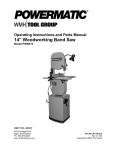
SPINDLE SHAPER
Model TS29
Instruction Manual & Parts List
M-0460270
(800) 274-6848
www.wmhtoolgroup.com
This manual has been prepared for the owner and operators of a Powermatic Model TS29 Spindle
Shaper. Its purpose, aside from machine operation, is to promote safety through the use of
accepted correct operating and maintenance procedures. Completely read the safety and maintenance instructions before operating or servicing the machine. To obtain maximum life and
efficiency from your shaper and to aid in using the machine safely, read this manual thoroughly
and follow all instructions carefully.
Warranty & Service
WMH Tool Group warrants every product it sells. If one of our tools needs service or repair, one of our Authorized Repair Stations located throughout the United States can give you quick service.
In most cases, any one of these WMH Tool Group Repair Stations can authorize warranty repair, assist you in
obtaining parts, or perform routine maintenance and major repair on your JET, Powermatic, Performax, or
Wilton tools.
For the name of an Authorized Repair Station in your area, call 1-800-274-6848.
More Information
WMH Tool Group is consistently adding new products to the line. For complete, up-to-date product information,
check with your local WMH Tool Group distributor or visit wmhtoolgroup.com.
WMH Tool Group Warranty
WMH Tool Group makes every effort to assure that its products meet high quality and durability standards and
warrants to the original retail consumer/purchaser of our products that each product be free from defects in
materials and workmanship as follows: 1 YEAR LIMITED WARRANTY ON ALL PRODUCTS UNLESS
SPECIFIED OTHERWISE. This warranty does not apply to defects due directly or indirectly to misuse, abuse,
negligence or accidents, normal wear-and-tear, repair or alterations outside our facilities, or to a lack of maintenance.
WMH TOOL GROUP LIMITS ALL IMPLIED WARRANTIES TO THE PERIOD SPECIFIED ABOVE, FROM THE
DATE THE PRODUCT WAS PURCHASED AT RETAIL. EXCEPT AS STATED HEREIN, ANY IMPLIED WARRANTIES OR MERCHANTIBILITY AND FITNESS ARE EXCLUDED. SOME STATES DO NOT
ALLOW LIMITATIONS ON HOW LONG THE IMPLIED WARRANTY LASTS, SO THE ABOVE LIMITATION MAY
NOT APPLY TO YOU. WMH TOOL GROUP SHALL IN NO EVENT BE LIABLE FOR DEATH, INJURIES TO
PERSONS OR PROPERTY, OR FOR INCIDENTAL, CONTINGENT, SPECIAL, OR CONSEQUENTIAL DAMAGES ARISING FROM THE USE OF OUR PRODUCTS. SOME STATES DO NOT ALLOW THE EXCLUSION
OR LIMITATION OF INCIDENTAL OR CONSEQUENTIAL DAMAGES, SO THE ABOVE LIMITATION OR EXCLUSION MAY NOT APPLY TO YOU.
To take advantage of this warranty, the product or part must be returned for examination, postage prepaid, to an
Authorized Repair Station designated by our office. Proof of purchase date and an explanation of the complaint
must accompany the merchandise. If our inspection discloses a defect, WMH Tool Group will either repair or
replace the product, or refund the purchase price if we cannot readily and quickly provide a repair or replacement, if you are willing to accept a refund. WMH Tool Group will return repaired product or replacement at our
expense, but if it is determined there is no defect, or that the defect resulted from causes not within the scope
of our warranty, then the user must bear the cost of storing and returning the product. This warranty gives you
specific legal rights, you may also have other rights which vary from state to state.
WMH Tool Group sells through distributors only. WMH Tool Group reserves the right to effect at any time,
without prior notice, those alterations to parts, fittings, and accessory equipment which they may deem necessary for any reason whatsoever.
TABLE OF CONTENTS
Safety Rules ...................................................................................................................................... 4-6
Safety Decals ....................................................................................................................................... 7
Specifications ........................................................................................................................................ 8
Standard Accessories ........................................................................................................................... 9
Unpacking ............................................................................................................................................. 9
Installation & Assembly ......................................................................................................................... 9
Electrical Connections .................................................................................................................. 10
Interchangeable Spindle Installation .............................................................................................. 11
Installing Cutters ........................................................................................................................... 12
Fence Assembly ........................................................................................................................... 13
Guard Assembly ........................................................................................................................... 13
Dust Chute ................................................................................................................................... 13
Mitre Gauge & Clamp ................................................................................................................... 13
Mitre Fence .................................................................................................................................. 14
Adjustments
Control Panel Instructions ............................................................................................................. 14
Speed Change .............................................................................................................................. 15
Spindle Lock ................................................................................................................................. 15
Spindle Vertical Travel ................................................................................................................... 16
Spindle Tilting ............................................................................................................................... 16
Fence Adjustment ......................................................................................................................... 16
Sliding Table Adjustment ............................................................................................................... 17
Operation ............................................................................................................................................ 18
Position of Collars ......................................................................................................................... 18
Copying (Machining with a Jig) ...................................................................................................... 19
Feeding Stock .............................................................................................................................. 19
Maintenance ....................................................................................................................................... 20
Trouble-Shooting ............................................................................................................................ 21-22
Parts Lists & Exploded Views:
Fence Assembly ......................................................................................................................
Spindle Assembly ....................................................................................................................
Cabinet Assembly ....................................................................................................................
Sliding Table Assembly ............................................................................................................
Speed Indicator ........................................................................................................................
Electrical Components .............................................................................................................
Quill Assembly ........................................................................................................................
23-25
26-27
28-29
30-31
32-33
34-35
36-38
Electrical Schematic ........................................................................................................................... 39
!
SAFETY RULES
As with all machines, there is a certain amount of hazard involved with the use of this shaper. Use the
machine with the respect and caution demanded where safety precautions are concerned. When normal
safety precautions are overlooked or ignored, personal injury to the operator can result.
Read, understand and follow the safety and operating instructions found in this manual. Know the limitations and hazards associated with this machine.
Electrical grounding. Make certain that the machine frame is electrically grounded and that a ground lead is
included in the incoming electrical service. In cases where a cord and plug are used, make certain that the
grounding plug connects to a suitable ground. Follow the grounding procedure indicated in the National Electrical Code.
Eye safety. Wear an approved safety shield, goggles, or glasses to protect eyes. (NOTE: Common eyeglasses are only impact-resistant, they are not safety glasses.)
Personal protection. Before operating the machine, remove tie, rings, watch and other jewelry and roll up
sleeves above the elbows. Remove all loose outer clothing and confine long hair. Protective type footwear
should be used. Where the noise exceeds the level of exposure allowed in Section 1910.95 of the OSHA
Regulations, use hearing protective devices. Do not wear gloves.
Guards. Keep the machine guards in place for every operation for which they can be used. If any guards are
removed for maintenance, DO NOT OPERATE the machine until the guards are reinstalled.
Work area. Keep the floor around the machine clean and free of scrap material, saw dust, oil and other liquids
to minimize the danger of tripping or slipping. Be sure the table is free of all scrap, foreign material and tools
before starting to cut. Make certain the work area is well lighted and that a proper exhaust system is used to
minimize dust. Powermatic recommends the use of anti-skid floor strips on the floor area where the operator
normally stands and that each machine’s work area be marked off. Provide adequate work space around the
machine.
Operator position. Maintain a balanced stance and keep your body under control at all times. Do not
overreach. Do not stand in line with the work piece and do not allow anyone else to do so. Never climb on or
near the machine.
Housekeeping. Before turning on machine, remove all extra equipment such as keys, wrenches, scrap, and
cleaning rags away from the saw.
Tool maintenance. Clean and sharp tools give better and safer performance. Dull tools can cause kickback
and excessive chatter. Before making a cut, always check the condition and adjustment of the tools. Never
use a tool that is not balanced and rated for the selected RPM.
Careless acts. Give the work you are doing your undivided attention. Looking around, carrying on a conversation, and “horseplay” are careless acts that can result in serious injury.
Disconnect machine before performing any service or maintenance or when changing cutters. A machine
under repair should be RED TAGGED to show it should not be used until the maintenance is complete.
Hand safety. Keep hands clear of the cutter area. Do not reach past the blade to clear parts or scrap with the
saw blade running. Never saw free hand. Avoid awkward operations and hand positions where a sudden slip
could cause your hand to contact the blade.
Job completion. If the operator leaves the machine area for any reason, he should turn “off” the power to the
machine and wait until the cutter comes to a complete stop before his departure. In addition, if the operation is
complete, he should clean the table and cutter area. Never clean off the machine with power “on” and never use
the hands to clear sawdust and debris; use a brush.
4
Short stock. Never shape stock less than 12 inches in length without special fixtures. Where practical, shape
longer stock and cut to size.
12 inch rule. When shaping, never allow your hands to
come closer than 12 inches to the cutters.
Hand safety. Never pass the hands directly over or in
front of the cutters. As one hand approaches the 12
inch radius point, remove it (or the push stick) in an arc
motion and reposition hands 12 inches beyond the
cutters. See Figure 1.
Collars. When shaping with collars, the collar must
have sufficient bearing surface (see page 18). The work
must also be fairly heavy in proportion to the cut being
made. Do not use short, lightweight stock when
shaping against collars.
FIGURE 1
The opening between the fence plates should be only
just enough to clear the cutter.
Edge shaping. Always use the mitre gauge and clamp
attachment when edge shaping stock less than 6" wide.
The fence should be removed during this operation.
Feed stock opposite to the direction of the cutter
rotation. Never back stock out of the cutter once the
cut has been started. Instead, pull the stock straight
back away from cutter and begin the cut again. See
Figure 2.
Make sure the spindle and the draw bar are tightened
on the arbor.
FIGURE 2
Safety lock washer. Never operate the shaper without the safety locking keyed washer located immediately
under the spindle nut. See Figure 3. This prevents the nut from coming loose when the spindle is run in a
counterclockwise direction. Do not substitute any other
type washer in place of the safety lock washer.
Replacement parts. Use only Powermatic or factory
authorized replacement parts and accessories; otherwise the shaper warranty and guarantee is null and void.
Misuse. Do not use this Powermatic shaper for other
than its intended use. If used for other purposes,
Powermatic disclaims any real or implied warranty and
holds itself harmless for any injury or damage which
may result from that use.
If you are not thoroughly familiar with the operation of
spindle shapers, obtain advice from your supervisor,
instructor or other qualified person.
FIGURE 3
Drugs, alcohol, medication. Do not operate this machine while under the influence of drugs, alcohol, or any
medication.
5
Health hazards. Some dust created by power sanding, sawing, grinding, drilling and other construction
activities contains chemicals known to cause cancer, birth defects or other reproductive harm. Some examples of these chemicals are:
* Lead from lead-based paint.
* Crystalline silica from bricks and cement and other masonry products.
* Arsenic and chromium from chemically-treated lumber.
Your risk from these exposures varies, depending on how often you do this type of work. To reduce your
exposure to these chemicals, work in a well-ventilated area, and work with approved safety equipment, such
as those dust masks that are specifically designed to filter out microscopic particles.
Familiarize yourself with the following safety notices used in this manual:
!
!
6
CAUTION: (This means that if precautions are not heeded, it may result in minor or moderate injury
and/or possible machine damage)
WARNING: (This means that if precautions are not heeded, it could result in serious injury or
possibly even death).
! SAFETY
Familiarize yourself with the location and content of these safety decals on your shaper.
FIGURE 4
WARNING
DO NOT ENGAGE
SPINDLE LOCK WHILE
MACHINE IS RUNNING
6293077
7
SPECIFICATIONS: Model TS29 Spindle Shaper
Motor ...................................................................... TEFC 7.5HP, 3Ph, 230/460V, 60Hz
Starter ...................................... 230/460V Magnetic w/ 24V low voltage control circuit
Overall dimensions .............................................................. 51-1/4" L x 44" W x 53" H
Table size .................................................................................... 51-1/4" L x 33-1/2" W
Sliding table size ........................................................................ 51-1/4" L x 11-1/4" W
Sliding table travel .............................................................................................. 49-1/4"
Tilting spindle ........................................................... 5 degree back, 45 degree forward
Spindle travel ............................................................................................................... 7"
Spindle speed ................................................................... 3000-4000-6000-8000-10000
Spindles ..................................... interchangeable: 1-1/4" x 6"; 1" x 6"; 3/4" x 3-1/4";
and 1/2" collet chuck with 1/4" bushing
Table inserts (three) ............................................... 2-1/2" I.D.; 5-1/2" I.D.; Oval slotted
Dust outlet ......................................................................................................... (two) 5"
Net weight ........................................................................................................ 1183 lbs.
NOTE: The above specifications were current at the time this manual was published, but because of our policy
of continuous improvement, Powermatic reserves the right to change specifications without notice and without
incurring obligations.
8
Standard Accessories
(Figure 5)
A.
B.
C.
D.
E.
F.
G.
H.
J.
K.
L.
Spindle Nut Wrench
Spindle Wrenches
Open-end Wrenches
Hex Wrenches
Spindle Collet
Spindle Nut
Lock Nut
Draw Bar
Grease Gun
Table Inserts
Interchangeable
Spindles
FIGURE 5
UNPACKING
Open shipping container and all separate cartons containing accessories. Report any damage immediately
to your distributor. Read the instruction manual thoroughly for assembly, alignment, maintenance and
safety instructions.
Crate contents:
1 shaper
1 fence assembly
1 dust chute
1 mitre gauge and clamp assembly
1 aluminum fence
1 box of standard accessories (see above)
FIGURE 6
INSTALLATION AND ASSEMBLY
Tools required
crane with hoist; or forklift
9/16", 7/16" and 1/2" wrenches
1.
Remove all wood crating from around the shaper.
2. Remove the bolts securing the machine to the
skid.
3. The shaper can be lifted by a crane with hoist
(Figure 6), or by a forklift (Figure 7), either of which
should be capable of lifting one ton. Remove the skid
from under the shaper.
4. The shaper should be mounted to a solid, level
foundation, preferably a concrete floor. With machine
in position, check table surface left to right and front
to back with a machinist's level. If necessary, place
metal shims under the corners of the machine to ensure it is level.
FIGURE 7
9
5. Secure the machine to the floor with good quality lag screws through the holes in the bottom of the
cabinet.
6. Exposed metal parts such as the table top have
been given a protective coating at the factory. This
should be removed with a soft cloth and solvent (such
as mineral spirits). Do not use an abrasive pad.
ELECTRICAL CONNECTIONS
!
WARNING: Electrical connections must
be made by a qualified electrician. The
machine must be properly grounded to
help prevent electrical shock and possible
death.
FIGURE 8
Before connecting power, make sure the electrical
current of your power source matches the electrical
system on the shaper.
To connect power, proceed as follows:
1. Remove two screws (A) and remove terminal strip
cover (B). See Figure 8.
2. Remove clear plastic insulator (C) that covers the
terminals. See Figure 9.
FIGURE 9
3. Insert power line through opening (D) of terminal
strip box, shown in Figure 8.
4. Connect the three power lines to terminals L1,
L2 and L3, as shown at (E) Figure 10. Also connect
the green ground wire to terminal (F).
5. Reassemble the clear plastic insulator (C) and
the terminal strip cover (B).
!
CAUTION: Make sure the incoming power
matches the voltage on the motor plate.
6. When wiring is completed, tape all power box
joints to keep out dust.
FIGURE 10
7. Turn the machine on and make sure the direction of the shaft rotation is correct. Looking down on
the top of the spindle, the spindle should be turning
counterclockwise as shown in Figure 11. If it is not,
reverse any two incoming power leads.
!
10
WARNING: After connecting this machine
to the power source, the terminal box is
still electrified even while the power switch
is shut off.
FIGURE 11
INTERCHANGEABLE SPINDLE
INSTALLATION
One of the features of this machine is that it will accept interchangeable spindles with a drawbar or without a draw bar. Router bits can also be used on this
shaper.
INTERCHANGEABLE SPINDLE WITH DRAWBAR
1. Disconnect the machine from the power source
and remove the table inserts (NOTE: Removing the
tilting insert is not neccessary).
2.
FIGURE 12
Raise the spindle shaft all the way up.
3. Thoroughly clean the taper of the interchangeable spindle and the internal taper of the shaft with a
soft cloth moistened with kerosene or mineral spirits
(do not use gasoline or lacquer thinner).
4. Thread the short threaded end of the draw bar
(B) into the threaded hole in the bottom of the interchangeable spindle (A). See Figure 12. Remove the
two lock nuts and the special bevel washer from the
other end of the draw bar (B).
FIGURE 13
5. Carefully insert the draw bar (B) and spindle (A)
down through the shaft as shown in Figure 12. Make
sure the tang (C) on the spindle is engaged with the
notch (D), and thread spindle nut (E) onto threads (F).
6. Engage spindle lock [refer to "Spindle Lock" on
page 16].
7. Use the supplied spanner wrench (G), to tighten
the spindle nut (E), shown in Figure 13.
8. Open the cabinet door and assemble the special
bevel washer (H) to the bottom of the draw bar (B) as
shown in Figure 14.
FIGURE 14
9. Assemble and securely tighten the two lock nuts
(I) with a 19mm wrench. See Figure 14.
10. Disengage the spindle lock.
INSTALLING CUTTERS
1. Disconnect machine from power source and engage spindle lock.
2. Place cutter (A) and desired spindle collars (B)
on the spindle as shown in Figure 15.
3. Install keyed washer (C) and tighten nut (D) using the supplied wrench.
FIGURE 15
11
4.
Disengage spindle lock before operating.
NOTE: Whenever possible, the cutter should be positioned on the spindle in such a way that the cut is
being performed under the surface of the workpiece.
!
WARNING: Always place the "keyed"
washer (C) on the spindle before threading
the nut.
FENCE ASSEMBLY
1. Place fence body (A), shown in Figure 16, on the
table. Mount the two fence locking handles (E) with
washers, and secure fence to table using one of the
two sets of holes on the table.
FIGURE 16
2. Fasten bar (B) to the front of the fence half using
the locking lever (C) and washer, shown in Figure 17.
Slide an aluminum fence (D) onto the bar. (NOTE: Right
hand and left hand fences are slightly different.) Repeat for other side.
NOTE: Locking levers (C) are spring loaded and can
be repositioned by pulling out the handle and rotating
it on the nut.
3. Mount the cover plate (K) using the two locking
knobs and flat washers, shown in Figure 16.
FIGURE 17
GUARD ASSEMBLY
The guard assembly can be mounted in various configurations, depending upon the type of work being
done. Figure 16 shows one such configuration.
1. Mount the spring guard (F), hold-down (G) and
clear plastic guard (H) to mounting rod (J) located on
top of fence cover (K), using rod and clamps. The latch
on the mounting rod (L) can be pushed down to help
secure the guards in place.
2. The spring guard (F), hold-down (G) and clear
plastic guard (H) can be flipped up out of the way when
not in use or when making adjustments. Simply pull
up the latch (L) and flip the entire assembly to the
back.
DUST CHUTE
Mount the dust chute to rear edge of table using the
two M5 x 10 screws and M5 flat washers. See Figure
18.
FIGURE 18
12
MITRE GAUGE & CLAMP
Mount mitre gauge and clamp to the sliding table as
follows (Figure 19):
1. Insert post (A) of the clamp assembly down
through hole (B) of the mitre gauge body (C), and thread
post (A) into hole (D) of sliding table.
2. Insert shaft of locking handle (E) down through
opening (F) of mitre gauge and thread shaft into hole
(G) of sliding table.
3. The clamp (H), shown in Figure 20, is supplied
with the mitre gauge to securely hold the workpiece
when shaping small pieces across the grain. The
clamp should be mounted as shown, and can be adjusted by loosening the screws (J).
FIGURE 19
MITRE FENCE
1. Slide the mitre fence (A) on to the two square
nuts (B) that are attached to the threaded part of the
locking levers (C). See Figure 21.
2. To slide mitre fence (A) to the left or right, loosen
locking levers (C), slide fence (A) to the desired position and tighten locking levers (C). To change the angle
of the fence loosen locking handle (D). A scale (E) is
provided to indicate the mitre angle of the fence.
FIGURE 20
3. Loosen locking screw (I) and insert nut (J) of stock
stop assembly into channel on end of fence as shown.
See Figure 22.
4. Slide workstop (K) to desired position on fence
and tighten locking screw (I), as shown in Figure 23.
FIGURE 21
FIGURE 22
FIGURE 23
13
ADJUSTMENTS
Control Panel Instructions
The elements of the control panel are as follows:
(See Figure 24).
A.
B.
C.
D.
E.
power indicator
on-off switch
forward/reverse switch
start indicator
emergency stop
1. Make certain the spindle lock is disengaged as
explained in the section "Spindle Lock" and that the
cabinet door is closed. Be sure there is no conflict
with the cutterhead, and that any bystanders are clear
of moving parts.
FIGURE 24
2. Rotate the forward/reverse switch (C) to the desired setting. Rotate the start switch (B) to the right to
start the machine. The start switch is magnetic; as
soon as the machine is started, the switch will return
to the center position as shown.
!
WARNING: Never attempt to reverse the
rotation of the spindle while the motor/
spindle is running.
3. To stop the machine, push the mushroom shaped
stop button (E) or turn the start/stop switch (B) to the
left.
!
CAUTION: Do not use the forward/reverse
switch to stop the machine or damage to
the electrical controls will occur.
!
WARNING: Open the electrical cabinet door
only while the power is disconnected, or it
may result in electrical shock.
FIGURE 25
SPEED CHANGE
Your machine is supplied with a 5-step motor pulley
and a 5-step spindle pulley that provide spindle speeds
of 3000, 4000, 6000, 8000 and 10000 RPM.
A speed chart, shown in Figure 25, is located on the
inside of the front cabinet door for easy reference of
the belt position on the pulleys for the five speeds available.
Check machine speed setting before operating. Make
sure cutter meets or exceeds speed rating of tool.
Figure 26 shows a chart for finding optimum speed
range in relation to the cutter size. A similar chart can
be seen on the front of the shaper, with indicator lights
showing the current speed of rotation.
14
FIGURE 26
The cutting speed should always exceed 40 m/s to
lessen risk of kickback but should not exceed 70 m/s
to lessen the risk of tool damage.
To change the speed and adjust the proper belt tension, proceed as follows:
1.
Disconnect machine from power source.
2. Open front cabinet door and move belt tension
lever (A) to the right to loosen belt tension. See Figure 27.
3. Move the belt (B) to the desired position on the
pulleys, while at the same time rotate the knob (C) on
the speed indicator so that the belt will remain positioned in the cut-out in the speed bar.
FIGURE 27
4. When the belt is positioned properly, move the
tension lever (A) to the left.
NOTE: During the first use after speed adjustment,
the belt will settle and produce a slight decrease in
tension. To obtain best tension, turn the two nuts (E
& F - Figure 27).
Proper belt tension is achieved when the belt midway
between the pulleys can be deflected using moderate
finger pressure.
SPINDLE LOCK
The spindle lock will assist you in replacing the spindle
or installing and removing cutters.
NOTE: The spindle lock can be engaged only when
the machine has stopped completely.
Open rear cabinet door and rotate lock knob (A), shown
in Figure 28, until the hole on the knob engages the
pin. Turn pulley until the lock pin engages the spindle.
FIGURE 28
!
CAUTION: Make sure the spindle is
unlocked before turning on the machine.
SPINDLE VERTICAL TRAVEL
1. Loosen handwheel lock (A), shown in Figure 29,
and turn handwheel (B) counterclockwise to raise the
spindle; clockwise to lower the spindle.
NOTE: One complete revolution of the handwheel
moves the spindle up or down by .1" (2.5mm), as shown
in the label beside the handwheel.
FIGURE 29
2.
Re-tighten lock (A).
15
SPINDLE TILTING
The machine should come to a complete stop before
the spindle is tilted, and the insert with the oval slot
should be placed into the table. Make sure the cutter
does not touch the table or the fence when in tilted
position.
1. Loosen the knob (C) on the front handwheel (D).
See Figure 29.
2. Loosen the two locking handles (E) on both sides
of the machine.
3. Turn the handwheel (D) to the required tilting angle
shown on the indicator (F).
4.
Tighten the knob (C) and locking handles (E).
FENCE ADJUSTMENT
1. To adjust the aluminum fence halves endwise,
loosen the two fence locking levers (C-Figure 17), slide
the fence halves to the required positions and tighten
locking levers.
!
CAUTION: The aluminum fence halves
should be adjusted inward so that the
opening at the spindle is just enough to
clear the cutter.
2. The right fence half (infeed) can be moved independently, in or out, depending on the type of shaping
operation that is being performed. See Figure 30. To
move the right fence half in or out, loosen the locking
knob (A) and turn the adjusting knob (B). Precise
movements are possible by using the dial indicator
beneath the knob. When finished, re-tighten locking
knob (A).
3. The complete fence assembly can be rapidly
positioned on the table by loosening two locking
handles (C) and moving the fence assembly to desired position by rotating the handwheel (D). Use the
dial indicator for more precise measurement. Retighten the handles (C) when finished.
16
FIGURE 30
SLIDING TABLE ADJUSTMENT
There are six adjustable eccentric rollers (A) on the
sliding table, shown in Figure 31. Wherever the table
is unstable or not traveling in line, adjust the sliding
table as follows:
1.
Use open end wrench (B) to adjust the rollers.
2.
Lock the rollers by using the hex wrench (C).
To operate the sliding table (F) pull out and rotate knob
(D) until it stays in the out position as shown. The
sliding table can then be moved back and forth.
To lock the sliding table, preventing it from moving,
simply rotate knob (D) until the pin on the knob engages the hole underneath the table.
FIGURE 31
OPERATION
Using the fence is the safest and most satisfactory
method of shaping, and it should always be used when
the work permits. Almost all straight work can be
done with the fence.
1. For normal work, where a portion of the original
edge of the stock is not touched by the cutter, both
the infeed and outfeed fences are in a straight line, as
shown in Figure 32.
2. When the shaping operation removes the entire
edge of the stock, e.g. in jointing or making a full bead,
the shaped edge will not be supported by the outfeed
fence when both fences are in line, as shown in Figure
33. In this case, the stock should be advanced to the
position shown in Figure 33 and stopped. The outfeed
fence should then be moved forward to contact the
work, as shown in Figure 34. The outfeed fence will
then be in line with the cutting circle, and the operation can continue.
!
FIGURE 32
FIGURE 33
WARNING: Keep guards in place and in
working order. Always use fence assembly
when the work permits.
FIGURE 34
17
POSITION OF COLLARS
When shaping with collars, the collar must have sufficient bearing surface, as shown in Figure 35. Also
the work must be fairly heavy relative to the cut being
made. Under no circumstances should a short, light
workpiece be shaped against the collars, as shown in
Figure 36.
The collars may be used in any of the following positions: above, below, or between the cutters.
1. When the collar is used below the cutter, as shown
in Figure 37, the progress of the cut can be seen
throughout the operation. However, any accidental lifting of the work will gouge the wood and ruin the
workpiece.
FIGURE 35
2. When the collar is used above the cutter, as shown
in Figure 38, the cut can not be seen, but this method
offers an advantage in that the cut is not affected by
slight variations in the thickness of the stock. Also,
accidental lifting of the workpiece will not gouge the
workpiece; simply repeat the operation to correct the
mistake.
3. Using the collar between two cutters has the
advantages and disadvantages of the first two procedures, and is frequently used where both edges of the
work are to be molded. See Figure 39.
FIGURE 36
NOTE: It is advisable to place the cutter as low as
possible on the spindle to reduce spindle deflection
and ensure the best possible finish. Also make sure
that the contacting surfaces of the cutter are smooth,
sharp, clean and without dents.
FIGURE 37
FIGURE 38
FIGURE 39
18
COPYING (MACHINING WITH A JIG)
When using the same procedure on multiple
workpieces, a jig or template can be made to facilitate
the operation:
1. Prepare the jig (A) to accomodate your original
workpiece. See Figure 40.
2. Place the jig (A) against the table ring guide shoulder (B).
FIGURE 40
3. Fasten the new workpiece (C) on the jig (A) with
the clamp (D) and push the assembly past the cutter.
FEEDING STOCK
Stock feeders are available from Powermatic. These
units mount to the shaper table, and will help ensure
smooth, consistent feed of material, as well as keep
hands safely away from the cutterhead.
1790800 3-Wheel Powerfeeder, 1HP, 3Ph, 230V
1790810 3-Wheel Powerfeeder, 1HP, 3Ph, 460V
1790811 4-Wheel Powerfeeder, 1HP, 3Ph, 230V
MAINTENANCE
Periodically clean the inside of the machine of shavings and dust. This will increase machine performance
and extend its life.
Clean the spindle with compressed air.
Do not get oil on the pulleys and belts. If they are
dirty, use paper or a soft rag to clean and dry them.
Never place the v-belt under excessive strain, as this
can overload the motor and damage the bearings,
spindle or belt.
The table surface must be kept clean and free of rust
for best results. Some users prefer a paste wax coating. Another option is talcum powder applied with a
blackboard eraser rubbed in vigorously once a week;
this will fill casting pores and form a moisture barrier.
This method provides a table top that is slick and allows rust rings to be easily wiped from the surface.
Important also is the fact that talcum powder will not
stain wood or mar finishes as wax pickup does.
Lubrication
Apply a drop of light machine oil occasionally on the
ledge and wall of the table opening to facilitate the
changing of table inserts.
19
The bearings in the motor are sealed for life and do not
require lubrication.
The spindle bearing should be lubricated every 200
hours of use by using the grease gun (A) supplied.
See Figure 41. Two grease fittings, one of which (B) is
shown, are supplied on the spindle housing for this
purpose. The other grease fitting is directly opposite
fitting (B). Before lubricating, clean grease fittings (B)
thoroughly and then lubricate the spindle bearings with
two pumps of a good quality, non-hardening grease.
FIGURE 41
20
Trouble-Shooting for Model TS29 Shaper
PROBLEM
POSSIBLE CAUSE
SOLUTION [with page #]
Machine will not start.
1. Faulty switch.
2. Cord damaged.
1. Replace switch.
2. Have cord replaced by authorized
service person.
3. Check connection.
4. Check voltage.
5. Replace fuse, reset breaker.
3. Not connected to power source.
4. Connected to wrong voltage.
5. Fuse blown or circuit breaker tripped
at incoming power source.
Overload kicks out
frequently.
1. Extension cord too light or too long.
2. Feeding stock too fast.
3. Cutter is dull or has gum on it.
1. Replace with adequate size cord.
2. Feed stock more slowly.
3. Clean or replace cutter.
Tool does not come up
to speed.
1. Extension cord too light or too long.
2. Low current.
3. Motor not wired for correct voltage.
1. Replace with adequate size cord.
2. Contact local electric company.
3. Refer to motor nameplate for correct
wiring.
4. Release spindle lock knob.
4. Spindle is locked.
Machine makes
unsatisfactory cuts.
1. Dull cutter.
2. Gum or pitch on cutter.
3. Gum or pitch on table causing erratic
feed.
4. Feeding work in wrong direction.
Stock burns.
1. Dull cutter.
2. Cutter too deep.
1. Replace cutter. [11]
2. Remove cutter and clean with
turpentine and steel wool.
3. Clean table with turpentine and
steel wool.
4. Feed work against cutter rotation. [5]
3. Forcing work.
1. Sharpen by honing on flat side.
2. On hardwoods take light cuts; attain
full depth of cut with several passes.
3. Feed slowly and steadily.
Machine vibrates
excessively.
1. Damaged tool.
2. Stand or bench on uneven floor.
3. Bad v-belt.
4. V-belt not tensioned correctly.
5. Bent pulley.
6. Improper motor mounting.
1.
2.
3.
4.
5.
6.
Edge splits off on
cross-grain cut.
Characteristic of cut.
1. Make cross-grain cuts first then finish
with grain.
2. Use scrap block to support at end of
cut.
Raised areas on shaped
edge.
Variation in pressure which holds work
against cutter.
1. Keep work firmly against fence or
collars throughout pass.
2. Use hold-downs or stock feeder. [13]
Work pulled from hand
of cut
No support.
1. Use mitre gauge with clamp or holddown to start cut when shaping freehand; hold work firmly against fence.
2. Adjust the tension of spring plate.
Replace tool.
Reposition on flat, level surface.
Replace belt.
Adjust belt tension. [15]
Replace pulley.
Check and adjust motor mounting.
21
Trouble-Shooting for Model TS29 Shaper
PROBLEM
POSSIBLE CAUSE
SOLUTION [with page #]
Depth of cut not uniform.
1. Misalignment.
2. Side pressure not uniform.
1. Adjust outfeed fence.
2. Use hold-downs or stock feeder;
keep pressure against fence or
collars consistent.
Variation in height of cut.
1. Variation in pressure which holds work
down on table.
1. Keep pressure firm throughout pass,
use hold-downs; make pass slowly
and steadily.
Whenever possible, keep cutter
under stock. [19]
2. Engage spindle lock. [18]
2. Vertical lock not engaged.
Cuts not smooth.
1. Wrong R.P.M.
2. Feeding too fast.
3. Working against grain.
4. Cutting too deep.
Spindle does not raise
freely.
22
Sawdust and dirt in raising mechanisms.
1. Use faster speed.
2. Pass stock more slowly.
3. Work with grain whenever
possible.
4. On very deep cuts make several
passes.
Brush or blow out loose dust and dirt.
Parts List: Fence Assembly (TS29 Shaper)
No.
Part No.
Description
Quantity
1
2
3
4
5
6
7
8
9
10
11
12
13
14
15
16
17
18
19
20
21
22
23
24
25
26
27
28
29
30
31
32
33
34
35
37
38
39
40
41
42
43
44
45
46
49
50
51
52
53
54
55
56
TS29-001
TS-1503021
TS-236106
TS29-002
TS29-003
TS29-004
TS29-005
TS29-006
TS29-007
TS29-008
TS29-009
TS29-010
TS29-011
TS29-012
TS29-013
TS29-014
TS-1550061
TS-1534052
TS-1540061
TS29-195
TS-236105
TS-1541011
TS29-015
TS29-016
TS-1502021
TS29-017
TS-1502061
TS29-018
TS-1503051
TS29-019
TS-1540041
TS29-020
TS29-021
TS29-022
TS29-023
TS29-024
TS-1503071
TS29-025
TS29-026
TS29-027
TS29-028
TS-1524011
TS29-029
TS29-030
TS29-031
TS29-032
TS-1503061
TS29-033
TS29-034
TS-1512011
TS29-035
TS29-036
TS29-199
Spring Guard ....................................................................................................... 1
Socket Head Cap Screw, M6 x 10 ...................................................................... 1
Lock Washer, M6 ............................................................................................... 9
Hold-down ........................................................................................................... 1
Fence R.H. ......................................................................................................... 1
Fence L.H........................................................................................................... 1
Slide Bar............................................................................................................. 2
Fence End Cap R.H. ........................................................................................... 1
Clip ..................................................................................................................... 8
Post Clamp Block ............................................................................................... 4
Vertical Hex Post ................................................................................................ 1
Vertical Hex Post ................................................................................................ 1
Horizontal Hex Post - Short ................................................................................ 1
Fence Cap L.H. .................................................................................................. 1
Warning Label, for TS29 shield ........................................................................... 1
Clear Shield ........................................................................................................ 1
Flat Washer, M8 ................................................................................................. 5
Pan Head Phillips Machine Screw, M6 x 20 ....................................................... 1
Hex Nut, M8 ....................................................................................................... 1
Hex Socket Set Screw, M8 x 35 ......................................................................... 1
Lock Washer, M5 ............................................................................................... 2
Lock Nut, M5 ...................................................................................................... 2
Latch Handle ...................................................................................................... 1
Horizontal Hex Post - Long ................................................................................. 1
Socket Head Cap Screw, M5 x 10 ...................................................................... 2
Cam Washer ...................................................................................................... 2
Socket Head Cap Screw, M5 x 25 ...................................................................... 2
Guard Support Bracket ....................................................................................... 1
Socket Head Cap Screw, M6 x 20 ...................................................................... 6
Fence Cover Plate .............................................................................................. 1
Hex Nut, M6 ....................................................................................................... 2
Fence Body Casting ........................................................................................... 1
Beveled Flat Washer, M14 .................................................................................. 2
Lock Handle ....................................................................................................... 2
Lock Lever, M10 x 35 .......................................................................................... 2
Cover Plate ......................................................................................................... 1
Socket Head Cap Screw, M6 x 30 ...................................................................... 2
Fence Back Plate ............................................................................................... 1
Fence Ram ......................................................................................................... 1
Fence Adjustment Screw .................................................................................... 1
Housing .............................................................................................................. 1
Socket Set Screw, M8 x 8 .................................................................................. 7
Bushing .............................................................................................................. 1
Lower Dial Indicator ............................................................................................ 1
Adjustment Knob ................................................................................................ 1
Fence Guide ....................................................................................................... 1
Socket Head Cap Screw, M6 x 25 ...................................................................... 2
Worm Cover ........................................................................................................ 1
Worm Guide ....................................................................................................... 1
Socket Head Flat Screw, M4 x 10 ...................................................................... 4
Worm Base Cover ............................................................................................... 1
Worm Shaft ........................................................................................................ 1
Fence Locating Pin ............................................................................................. 2
23
Parts List: Fence Assembly (TS29 Shaper)
continued
No.
Part No.
Description
57
58
60
62
63
64
65
67
68
69
71
73
74
75
76
77
78
79
80
81
82
83
84
86
87
TS29-037
BB-6204
TS29-038
TS29-039
TS-1524041
TS29-040
TS29-041
TS-1505041
TS29-042
TS29-043
TS29-044
TS29-045
TS29-196
TS29-046
TS29-047
TS29-048
TS-1533042
TS-1550031
TS29-049
TS29-050
TS29-051
TS29-052
TS-1523011
TS29-053
TS-1502031
Retaining Ring .................................................................................................... 1
Ball Bearing 6204 ............................................................................................... 1
Bevel Gear .......................................................................................................... 1
Retainer .............................................................................................................. 1
Socket Set Screw, M8 x 16 ................................................................................ 2
Retainer, R42 ...................................................................................................... 1
Lock Knob, M12 ................................................................................................. 1
Socket Head Cap Screw, M10 x 30 .................................................................... 3
Worm Base ........................................................................................................ 1
Bevel Gear .......................................................................................................... 1
Collar .................................................................................................................. 1
M8 Knob w/Stud ................................................................................................. 2
Socket Set Screw, M5 x 4 .................................................................................. 1
Bushing .............................................................................................................. 1
Vertical Hex Post ................................................................................................ 1
Thumb Screw, M8 x 17 ....................................................................................... 8
Pan Head Phillips Machine Screw, M5 x 12 ....................................................... 4
Flat Washer, M5 ................................................................................................. 4
Bolt ..................................................................................................................... 1
Swivel Handle ..................................................................................................... 1
Handwheel .......................................................................................................... 1
Dust Port ............................................................................................................ 1
Socket Set Screw, M6 x 6 .................................................................................. 2
Upper Dial Indicator ............................................................................................ 1
Socket Head Cap Screw, M5 x 12 ...................................................................... 2
24
Quantity
Fence Assembly (TS29 Shaper)
25
Parts List: Spindle Assembly (TS29 Shaper)
No.
Part No.
Description
1
6293033
6293034
6293035
TS29-054
TS29-055
TS29-056
TS29-057
TS29-058
TS29-059
6293040
6293041
6293042
6293043
TS29-060
TS29-061
TS29-062
TS-1502041
TS29-063
BB-6008Z
TS29-064
TS29-065
TS29-066
TS29-067
BB-6206Z
TS29-068
TS29-069
TS29-070
TS-1523011
TS29-200
TS29-071
TS29-072
TS29-073
TS29-074
Spindle Nut, 3/4 .................................................................................................. 1
Spindle Nut, 1 ..................................................................................................... 1
Spindle Nut, 1-1/4 ............................................................................................... 1
Keyed Washer, 3/4 ............................................................................................. 1
Keyed Washer, 1 ................................................................................................ 1
Keyed Washer, 1-1/4 .......................................................................................... 1
Spacer, 3/4 (Set of 8 pcs.) .................................................................................. 1
Spacer, 1 (Set of 8 pcs.) ..................................................................................... 1
Spacer, 1-1/4 (Set of 8 pcs.) ............................................................................... 1
Retainer Nut, 1-1/4.............................................................................................. 1
Collet Nut, 1-1/4 .................................................................................................. 1
Bushing, 1/4 ....................................................................................................... 1
Collet Chuck, 1/2 ................................................................................................ 1
Interchangeable Spindle, 3/4 ............................................................................... 1
Interchangeable Spindle, 1 .................................................................................. 1
Interchangeable Spindle, 1-1/4 ............................................................................ 1
Socket Head Cap Screw, M5 x 16 ...................................................................... 4
Plate ................................................................................................................... 1
Bearing 6008Z .................................................................................................... 2
Key, M6 x 54 ...................................................................................................... 1
Retaining Ring, S40 ............................................................................................ 1
Spindle ................................................................................................................ 1
Spring Disk, 61.5 x 40.5 x 0.7 ............................................................................ 2
Bearing 6206Z .................................................................................................... 1
Spacer ................................................................................................................ 1
Spindle Pulley ..................................................................................................... 1
Pulley Nut ........................................................................................................... 1
Socket Set Screw, M6 x 6 .................................................................................. 1
Belt, 3V x 375 .................................................................................................... 1
3/4" Interchangeable Spindle Assembly (Items 1, 2, 3, 8)
1" Interchangeable Spindle Assembly (Items 1, 2, 3, 8)
1-1/4" Interchangeable Spindle Assembly (Items 1, 2, 3, 8)
Collet Chuck w/Bushing Assembly (Items 5 thru 7)
2
3
4
5
6
7
8
9
10
11
12
13
14
15
16
17
18
19
20
21
26
Quantity
Spindle Assembly (TS29 Shaper)
27
Parts List: Cabinet Assembly (TS29 Shaper)
No.
Part No.
Description
1
2
4
6
7
8
9
11
12
13
14
15
16
17
18
19
20
21
22
23
24
25
26
28
29
30
31
32
33
34
TS-1502041
TS29-075
TS29-076
TS29-077
TS29-078
TS-1533032
TS-1550031
TS-2360121
TS29-079
TS-236112
TS-2211451
TS29-080
TS-2244102
TS-154007
TS29-081
TS29-082
TS29-083
TS29-084
TS29-085
TS29-086
TS29-087
TS-1502021
TS29-088
TS-231121
TS29-089
TS29-090
TS29-091
TS29-092
TS29-093
TS29-094
Socket Head Cap Screw, M5 x 16 ...................................................................... 9
Table Insert, 2-1/2" I.D. ....................................................................................... 1
Table Insert, 5-1/2" I.D. ....................................................................................... 1
Table Insert (Tilting) ............................................................................................. 1
Dust Chute ......................................................................................................... 1
Pan Head Phillips Machine Screw, M5 x 10 ....................................................... 4
Flat Washer, M5 ................................................................................................. 4
Flat Washer, M12 ............................................................................................... 4
Cabinet ............................................................................................................... 1
Lock Washer, M12.............................................................................................. 5
Hex Cap Screw, M12 x 45 .................................................................................. 4
Control Panel ...................................................................................................... 1
Pan Head Phillips Machine Screw, M4 x 10 ....................................................... 3
Hex Nut, M10 ..................................................................................................... 2
Fixed Screw ....................................................................................................... 1
Spring ................................................................................................................. 1
Knob ................................................................................................................... 1
Front Cabinet Door.............................................................................................. 1
Front Door Handle ............................................................................................... 1
Latch Assembly .................................................................................................. 1
Hinge Bracket ..................................................................................................... 1
Socket Head Cap Screw, M5 x 10 ...................................................................... 2
Handwheel .......................................................................................................... 1
Cap Nut, M12 ..................................................................................................... 1
Knob w/Stud ....................................................................................................... 1
Tilting Scale Base ............................................................................................... 1
Rear Cabinet Door .............................................................................................. 1
Plastic Switch Cover ........................................................................................... 1
Speed Indicator Cover ......................................................................................... 1
Rear Door Latch Assembly ................................................................................. 1
28
Quantity
Cabinet Assembly (TS29 Shaper)
29
Parts List: Sliding Table Assembly (TS29 Shaper)
No.
Part No.
Description
1
2
3
4
5
6
7
8
9
10
11
12
13
14
15
16
17
18
19
20
21
22
23
24
25
27
28
29
30
31
33
34
35
39
40
41
42
43
44
45
46
47
48
49
50
51
TS29-095
TS-1504101
TS29-096
TS29-097
BB-6004ZZ
TS29-098
TS29-099
TS29-100
TS29-197
TS29-101
TS-236110
TS-1540072
TS29-102
TS29-103
TS29-104
TS29-105
TS29-106
TS-1523041
TS29-107
TS29-108
TS29-109
TS29-110
TS-1524031
TS29-111
TS-149105
TS29-112
TS29-113
TS29-114
TS29-115
TS29-116
TS-1550071
TS29-117
TS29-118
TS29-119
TS29-120
TS-1482071
TS29-121
TS-1481061
TS29-122
TS29-123
TS29-124
TS-1540031
TS29-125
TS29-126
TS29-127
TS29-128
Main Table .......................................................................................................... 1
Socket Head Cap Screw, M8 x 50 ...................................................................... 6
Ring Nut .............................................................................................................. 6
Bearing Race ...................................................................................................... 6
Ball Bearing 6004ZZ ............................................................................................ 6
Retaining Ring, R42 ............................................................................................ 6
Bushing .............................................................................................................. 6
Nut ...................................................................................................................... 1
Socket Set Screw, M5 x 30 ................................................................................ 1
Lock Ring ........................................................................................................... 1
Lock Washer, M10.............................................................................................. 3
Hex Nut, M10 ..................................................................................................... 1
Table Lock Pin .................................................................................................... 1
Spring ................................................................................................................. 1
Housing .............................................................................................................. 1
Roll Pin ............................................................................................................... 1
Clamp Casting .................................................................................................... 1
Socket Set Screw, M6 x 12 ................................................................................ 1
Plunger Pad ........................................................................................................ 1
Locking Arm ....................................................................................................... 1
Plunger ............................................................................................................... 1
Spring ................................................................................................................. 1
Socket Set Screw, M8 x 12 ................................................................................ 1
Horizontal Post ................................................................................................... 1
Hex Cap Screw, M10 x 35 .................................................................................. 2
Post Clamp......................................................................................................... 1
Vertical Post ....................................................................................................... 1
Retaining Ring, S25 ............................................................................................ 1
Lock Lever, M6 ................................................................................................... 2
Knob, M10 .......................................................................................................... 1
Flat Washer, M10 ............................................................................................... 1
Mitre Gauge Body ............................................................................................... 1
Sliding Table ....................................................................................................... 1
Aluminum Fence ................................................................................................ 1
Knob w/ Stud ...................................................................................................... 1
Hex Cap Screw, M6 x 35 .................................................................................... 1
Scale .................................................................................................................. 1
Hex Cap Screw, M5 x 25 .................................................................................... 1
Lock Lever .......................................................................................................... 1
Sliding Block ...................................................................................................... 1
Stop Plate ........................................................................................................... 1
Hex Nut, M5 ....................................................................................................... 1
Extension Bar ..................................................................................................... 1
Knob w/ Stud ...................................................................................................... 1
Support Fence .................................................................................................... 1
Scale .................................................................................................................. 1
30
Quantity
Sliding Table Assembly (TS29 Shaper)
31
Parts List: Speed Indicator (TS29 Shaper)
No.
Part No.
Description
1
2
3
4
5
6
7
8
9
10
11
12
13
TS29-129
TS29-130
TS29-131
TS29-132
TS29-133
TS29-134
TS29-135
TS29-201
TS29-202
TS29-136
TS29-203
TS29-137
TS29-138
Belt Fork ............................................................................................................ 1
Fork Slide .......................................................................................................... 2
Rack .................................................................................................................. 1
Gear ................................................................................................................... 1
Block ................................................................................................................. 1
Mount Bracket ................................................................................................... 1
Sensor ............................................................................................................... 1
Pan Head Machine Screw, 5/32 x 1-1/4 Lg ........................................................ 5
Pan Head Machine Screw, 5/32 x 1-1/2 Lg ........................................................ 1
Terminal ............................................................................................................. 1
Hex Nut, 5/32 .................................................................................................. 13
Spring ................................................................................................................. 1
Steel Ball, 1/4 .................................................................................................... 1
32
Quantity
Speed Indicator (TS29 Shaper)
33
Parts List: Electrical Components (TS29 Shaper)
No.
Part No.
Description
1
2
3
4
5
6
7
TS29-139
TS29-140
TS29-141
TS29-142
TS29-143
TS29-144
TS29-145
Speed Indicator Light.......................................................................................... 5
Stop Button ........................................................................................................ 1
Start Switch ....................................................................................................... 1
Forward/Reverse Switch ..................................................................................... 1
Transformer ........................................................................................................ 1
Control Box ........................................................................................................ 1
Magnetic Starter w/Overload Relay .................................................................... 1
34
Quantity
Electrical Components (TS29 Shaper)
35
Parts List: Quill Assembly (TS29 Shaper)
No.
Part No.
Description
1
2
3
4
5
6
7
8
9
10
11
12
13
14*
15
16
17
18
19
20
21
22
23
24
25
26
27
28
29
30
31
32
33
34
35
36
37
38
39
40
41
43
44
45
46
47
48
49
50
51
52
53
54
TS-149105
TS-236110
TS29-146
TS29-147
TS29-148
TS-2279351
TS-1540071
TS29-149
TS29-150
TS-1491041
TS-1550071
TS29-151
TS29-152
TS-2288202
TS-1540061
TS29-153
TS-1550061
TS-1491031
TS-1502051
TS29-154
TS29-155
TS29-156
TS-1491081
TS29-157
TS29-158
TS29-159
TS-1491031
TS29-160
TS-154010
TS29-161
TS-2360121
TS-2211451
TS29-162
TS29-163
TS29-164
TS-2310162
TS29-165
TS29-166
TS29-167
TS-1540061
TS29-198
TS-1490021
TS-1502071
TS29-168
TS29-169
TS-0561051
TS29-170
TS29-171
TS29-172
TS29-173
TS29-174
TS29-175
TS29-176
Hex Cap Screw, M10 x 35 .................................................................................. 4
Lock Washer, M10.............................................................................................. 4
Motor Pulley ....................................................................................................... 2
Motor Shaft Sleeve.............................................................................................. 1
Retainer .............................................................................................................. 1
Socket Set Screw, M10 x 35 .............................................................................. 1
Hex Nut, M10 ..................................................................................................... 1
Motor Mount ....................................................................................................... 1
Belt Release Handle ........................................................................................... 1
Hex Cap Screw, M10 x 30 .................................................................................. 1
Flat Washer, M10 ............................................................................................... 3
Spacer ................................................................................................................ 1
Stud .................................................................................................................... 1
Pan Head Phillips Machine Screw, M8 x 20 ....................................................... 1
Hex Nut, M8 ....................................................................................................... 1
Linkage ............................................................................................................... 1
Flat Washer, M8 ................................................................................................. 2
Hex Cap Screw, M8 x 25 .................................................................................... 1
Socket Head Cap Screw, M5 x 20 ...................................................................... 4
Handle L.H.......................................................................................................... 1
Bushing L.H. ....................................................................................................... 1
Top Trunnion L.H. ................................................................................................ 1
Hex Cap Screw, M10 x 50 .................................................................................. 1
Spacer ................................................................................................................ 1
Bottom Trunnion L.H. .......................................................................................... 1
Trunnion Main Frame .......................................................................................... 1
Hex Cap Screw, M10 x 25 .................................................................................. 6
Spring Hook ........................................................................................................ 1
Hex Nut, M16 ..................................................................................................... 1
Quill Housing ...................................................................................................... 1
Flat Washer, M12 ............................................................................................... 5
Hex Head Bolt, M12 x 45 .................................................................................... 4
Raising Gear ....................................................................................................... 1
Base Plate .......................................................................................................... 1
End Cap .............................................................................................................. 1
Hex Nut, M16 ..................................................................................................... 1
Hex Head Bolt, M8 x 10 ..................................................................................... 1
Stud .................................................................................................................... 1
Spring ................................................................................................................. 1
Hex Nut, M8 ....................................................................................................... 3
Socket Set Screw, M8 x 50 ................................................................................ 1
Hex Cap Screw, M8 x 16 .................................................................................... 1
Socket Head Cap Screw, M5 x 30 ...................................................................... 4
Draw Bar ............................................................................................................. 1
Bevel Washer ..................................................................................................... 1
Hex Nut, 1/2-13 .................................................................................................. 2
Locking Post ...................................................................................................... 1
Key, 4 x 12mm ................................................................................................... 1
Raising Shaft ...................................................................................................... 1
Key, 4 x 24mm ................................................................................................... 1
Swivel Handle ..................................................................................................... 1
Outer Casing ...................................................................................................... 1
Retaining Ring .................................................................................................... 1
36
Quantity
Parts List: Quill Assembly (TS29 Shaper)
continued
No.
Part No.
Description
Quantity
55
56
57
58
60
61
62
63
64
65
66
67
68
69
70
71
72
73
74
75
76
77
78
79
80
81
82
83
TS29-177
TS-1503071
TS-1540081
TS29-178
TS-2331121
TS29-179
TS-1503041
TS29-180
TS29-181
TS-1502041
TS29-182
TS-1550061
TS29-183
TS29-184
TS29-185
TS29-186
TS29-187
TS-1523071
TS29-188
TS-1490071
TS29-189
TS29-190
TS-1502051
TS29-191
TS29-204
TS29-192
TS29-193
TS29-194
Handwheel .......................................................................................................... 1
Socket Head Cap Screw, M6 x 30 ...................................................................... 4
Hex Nut, M12 ..................................................................................................... 1
Handwheel .......................................................................................................... 1
Cap Nut, M12 ..................................................................................................... 1
Quill .................................................................................................................... 1
Socket Head Cap Screw, M6 x 16 ...................................................................... 1
Key ..................................................................................................................... 1
Fixed Nut ............................................................................................................ 1
Socket Head Cap Screw, M5 x 16 ...................................................................... 3
Segment Gear .................................................................................................... 1
Flat Washer, M8 ................................................................................................. 3
Inner Trunnion R.H. ............................................................................................. 1
Locking Post ...................................................................................................... 1
Locking Pin......................................................................................................... 1
Spring ................................................................................................................. 1
Spring Retainer ................................................................................................... 1
Socket Set Screw, M6 x 25 ................................................................................ 1
Lock Knob .......................................................................................................... 1
Hex Cap Screw, M8 x 40 .................................................................................... 3
Sleeve ................................................................................................................. 1
Handle R.H. ........................................................................................................ 1
Socket Head Cap Screw, M5 x 20 ...................................................................... 8
Tilt Shaft End Plate ............................................................................................. 1
Bearing ............................................................................................................... 2
Tilt Shaft ............................................................................................................. 1
Bearing Block ..................................................................................................... 1
Motor, 7.5HP, 3Ph, 230/460V, 60Hz, TEFC ......................................................... 1
37
Quill Assembly (TS29 Shaper)
38
Electrical Schematic (TS29 Shaper)
To order parts or reach our service department, please call our toll-free number between 7:30 a.m. and 6:00 p.m.
(CST), Monday through Friday. Having the Model Number and Serial Number of your machine available when you
call will allow us to serve you quickly and accurately. Locating the stock number of the part(s) required from your
parts manual will also expedite your order.
Phone No.: (800) 274-6848
Website: www.powermatic.com
39
08/02
WMH TOOLGROUP
2420 Vantage Drive
Elgin, IL 60123
Phone: (800) 274-6848
Website: www.wmhtoolgroup.com
C
POWERMATIC
ALL RIGHTS RESERVED