1
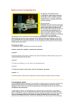
TECHNICAL MANUAL
L-JETRONIC
FUEL INJECTION SYSTEM
PORSCHE 912E
1
TABLE OF CONTENTS
1.0
2.0
3.0
4.0
5.0
6.0
7.0
8.0
Introduction to L-Jetronic Fuel Injection
L-Jetronic Fuel Injection Theory of Operation
L-Jetronic Component Identification
Operating Conditions
Troubleshooting the Porsche 912E Fuel Injection System
Component Location
System Diagrams and Reference Tables
Bibliography
2
1.0 L-JETRONIC INTRODUCTION
The Bosch L-Jetronic fuel injection system used in the Porsche 912E is often
referred to as the Air Flow Controlled or AFC fuel injection system. Originally,
Volkswagen adapted the L-Jetronic for the Type 4 air cooled 411 engines sold in
the United States due to more stringent emissions and fuel consumption
regulations. It was also used in the Porsche 914 with the 1.8L engine and
ultimately used in the Porsche 912E during the 1976 model year. The L-Jetronic
was a further development of the D-Jetronic found in the Porsche 914 1.7L and
2.0L engines. The original L-Jetronic found in the 914 1.8L engine was further
refined which resulted in the system installed in the 912E. The L-Jetronic
principles were later adapted for use in the Porsche 911 series models.
2.0 L-JETRONIC DESIGN APPROACH
The design approach used by Bosch for the L-Jetronic attempted to overcome
some of the limitations found in previous fuel injection systems as well as to meet
the more restrictive emission standards being regulated in the United States.
The design of the L-Jetronic injection system automatically takes into account all
changes in the engine which can occur during the service life of the vehicle
(abrasion, deposits in combustion chamber, changes in valve adjustment, etc.)
Uniform good quality of exhaust gases is therefore assured. In the L-Jetronic,
part of the exhaust gas can be re-circulated to lower the temperature in the
combustion chamber. The air-flow sensor measures only the fresh air drawn into
the engine and the control unit determines the quantity of fuel required only for
the quantity of fresh air. A supplementary mechanism for mixture enrichment
during acceleration is not required because the signal transmitted by the air-flow
sensor precedes charging of the cylinders. In addition, idle stability is improved.
The design of the L-Jetronic allows for fewer compensating adjustments during
the operating cycle of the fuel injection process as compared to the D-Jetronic.
This approach provides a more accurate fuel - air ratio that optimizes
performance under varying requirements. This is due to use of air-flow sensing
which takes direct account of a multitude of factors that influence the fuel
requirements of the engine.
3
3.0 PORSCHE 912E L-JETRONIC COMPONENTS
The following table provides a quick reference for the fuel injection components
used in the 912E.
FUEL INJECTION COMPONENTS FOR THE PORSCHE 912E
Component
Part Number (1)
Fuel Pump
923 601 111 00
0 580 463 010
Fuel Filter
923 110 176 00
0 450 905 001 0 450 905 062
Fuel Regulator
022 906 035
0 280 160 200
Fuel Injector Valves
923 606 109 00
0 280 150 105
Thermo-time Switch
923 605 101 00
0 280 130 214
Cold Start Valve
923 606 107 00
0 280 170 029
Air Flow Sensor
923 606 111 00
0 280 201 006
Auxiliary Air Regulator
022 906 045A
0 280 140 101
Temperature Sensor II
022 906 041
0 311 906 041A 0 280 130 012
Throttle Valve Switch
022 906 111 D
0 280 120 201
Electronic Control Unit
923 618 101 00
0 280 000 134
Injection Resistor Pack
0 280 159 001
Dual Relay
923 615 101 00
0 332 514 103/104/120
(1)
Part numbers beginning with 923 are Porsche part numbers. Part numbers
beginning with 022 are Volkswagen part numbers. Part numbers beginning with
0, followed by a 3 digit number (0 311 906 041A) are Bosch part numbers.
The components listed in the table can be functionally divided into three major
systems that are integrated to provide the correct injection pulse based on
specific operating conditions. The major systems are the fuel system, sensors,
and control unit. The fuel system provides the gasoline from the tank to the
injection valves, creates the pressure necessary for injection and maintains the
pressure at a constant value. The fuel system includes the pump, filter, pressure
regulator, cold start valve, and injectors. The sensors detect the various
parameters necessary to assure the correct injection pulse duration. The most
important parameter is the quantity of air that is used by the engine. The intake
air flow sensor provides this value as well as the temperature of the air entering
the engine. The throttle valve switch determines the position of the throttle (either
idle or wide open), and the temperature sensor determines the engine operating
temperature. Two additional devices, the thermo-time switch and the auxiliary air
regulator, are used during the starting phase to control fuel enrichment and
amount of air drawn into the engine. All of the parameters generated by the
sensors are then provided to the electronic control unit. The electronic control
unit processes these inputs and the input from the ignition distributor, which
represents engine speed, and provides the correct injector fuel pulse duration.
4
The following diagram provides an overview of how the fuel injection components
are integrated.
AIR FLOW
METER
ELECTRONIC CONTROL UNIT
INJECTORS
Injection
Pulse
Amount of Air Draw In
CYL 1
CYL 2
Temperature of Air Drawn In
CYL 3
THROTTLE
SWITCH
CYL 4
PUMP and
POWER RELAYS
Engine Load (WOT)
AUX AIR REGULATOR
Excess Air for Starting
IGNITION
DISTRIBUTOR
Engine Speed
STARTER
IGNITION
SWITCH
TEMPERATURE
SENSOR II
Engine Temperature
Excess Fuel for Starting
Battery
THERMO-TIME
SWITCH
COLD START
VALVE
Engine Temperature/Time
4.0 OPERATING CONDITIONS
There are six major operating conditions that the components of the L-Jetronics
fuel injection system must detect and provide inputs to the control unit in order to
provide the correct fuel-air mixture. These operating conditions are:
1.
2.
3.
4.
5.
6.
Cold Start
Warm Up
Idle During Warm Up
Load Adaptation
Temperature Adaptation
Coasting Adaptation
5
COLD START: When the ignition switch is initially turned on during the Cold
Start phase, it energizes the dual relay set which provides battery voltage to the
control unit and injection valves. When the starter is engaged, the relay set
provides battery voltage to the electric fuel pump, the cold start valve, the
thermo-time switch, and the auxiliary air regulator. During cold start and all other
load conditions, the fuel pressure regulator found in the 912E is able to maintain
an equal difference in pressure on all the injector valves regardless of load
conditions. This is due to a pressure diaphragm in the fuel regulator that is
controlled by the pressure levels in the intake manifold.
If the engine starts successfully, then battery voltage is maintained to the fuel
pump and auxiliary air regulator through contacts in the air flow sensor. If the
starting effort is not successful, then the battery voltage is removed from the fuel
pump to prevent cylinder flooding.
Additional fuel is provided to the engine during the initial period of the cold start
phase. This is necessary due to condensation of the fuel-air mixture as a result of
the cold engine. This cold start enrichment is based upon temperature
conditions and is accomplished by extending the duration period of the actual
injector valve opening time based on calculations by the electronic control unit.
Under certain temperature conditions, cold start enrichment is supplemented by
directly injecting atomized fuel from the cold start valve into the intake manifold
behind the throttle body. The length of time that cold start valve enrichment
occurs is controlled by the thermo-time switch. Several factors determine how
long the duration is. The length of time the cold start valve provides additional
fuel-air enrichment is dependent on temperature of the engine, outside air
temperature, and the heating element inside the thermo-time switch. Normally,
the cold start valve does not provide additional enrichment when the engine is
warm. The 912E thermo-time switch is designed to stay energized for 8 seconds
at temperatures below 350C or 950F. This is considerably different from
previous L-Jetronic fuel injection systems. In the 914 1.8L L-Jetronic system, the
cold start valve was not utilized at temperatures above 130C or 550F.
WARM UP: Considerable fuel enrichment is required for a period of time after a
cold start. For the first 30 seconds, up to 60% additional fuel will be provided to
facilitate the initial warm up period. The actual percentage varies based upon
the temperature. After the first 30 seconds, only a small amount of enrichment
is being provided. The amount of fuel enrichment is controlled by the
temperature sensor (Temperature Sensor II) installed in the cylinder head. The
electronic control unit calculates the amount of enrichment based upon the
Temperature Sensor II input.
IDLE DURING WARM-UP: When an engine is cold it has more frictional
resistance and requires compensation to overcome this condition. To adjust for
the frictional resistance, the L-Jetronic system is designed to provide additional
6
air during the idle period. This additional air is obtained via the auxiliary air
regulator that provides a bypass around the throttle valve and allows air to enter
directly into the manifold. This bypass route avoids any deflection by the throttle
valve. However, the additional intake air that is provided through the auxiliary air
device, does get detected by the air-flow sensor, which results in additional fuel
being supplied at the fuel injectors. The compensation for the additional air
provides more air-fuel mixture during warm up. During a cold start, the auxiliary
air device will be wide open. As the engine temperature increases, the size of
the opening decreases and eventually closes altogether. Additionally, the
auxiliary air device has an internal heater that is designed to provide a limited
opening time. The auxiliary air device should remain closed after normal engine
operating temperature is reached due to ambient heat from the engine.
LOAD ADAPTATION: The 912E engine continuously encounters varied engine
loading conditions. These can be broken down into four categories; idle, partial
load, full load, and acceleration. Air flow sensing takes the varied conditions into
account and provides inputs to the electronic control unit that provides the correct
injection duration for the load encountered.
The sensors and the electronic control unit normally control the idle load
condition. The air-flow sensor is designed to allow a small amount of air to
bypass the air flow sensor. The size of this opening can be adjusted to
compensate for lean conditions. This can be accomplished by adjusting the idlemixture screw found on the front of the air flow sensor. This adjustment does not
provide additional fuel to the engine, only air. Specific steps for this adjustment
are provided in Section 5.0. The 912E throttle valve switch does not provide an
input to the electronic control unit during the idle load condition as previously
found in the 914 1.8L L-Jetronic Fuel Injection System.
The majority of the time the engine encounters partial load conditions. The
electronic control unit has an internal program for this condition and provides the
correct injection pulse duration when normal driving conditions are detected by
the sensors. If a full load condition is detected, the mixture is enriched to provide
maximum output from the engine. The full load condition is detected by the
throttle valve switch that is connected to the throttle valve shaft. When the
accelerator pedal is fully depressed, a contact in the throttle valve switch is made
and this condition is detected and processed by the electronic control unit.
Sudden acceleration could result in variations in the fuel-air mixture that could
impact performance. Acceleration enrichment is required to avoid fuel-air
mixture problems. The additional fuel above the requirements detected by the air
flow sensor is provided to the engine as a result of the design of the sensor flap
in the air flow sensor. Sudden acceleration causes the sensor flap to swing
beyond its full open position for a short period of time before it returns to the
normal position. This over-swing of the sensor flap is detected by the electronic
control unit and results in an increase the quantity of fuel to the engine and
7
provides good acceleration response. If sudden acceleration is required during
the warm up phase of the engine, the acceleration enrichment provided by the
over-swing of the sensor flap may not be sufficient. If this condition is
encountered, then the electronic control unit also detects the speed of the
deflection of the sensor flap and adjusts the fuel accordingly.
ADAPTATION TO TEMPERATURE: Compensation for variations in air
temperature must be made. This is due to the fact that the density of the air will
affect the efficiency of combustion. Colder air is denser and provides a more
efficient combustion process than warmer air when the same throttle valve
position is used. The air flow sensor has a temperature sensor (Temperature
Sensor I) in the intake which measures the temperature of the air drawn into the
engine. The temperature measurement is provided to the electronic control unit
that compensates for the various temperatures by adjusting the amount of fuel
provided for the combustion process.
COASTING ADAPTATION: During normal driving conditions, the operator will
often lift his foot completely off of the accelerator pedal and coast. The electronic
control unit detects this operating condition and the result is that the injector
valves will be closed above a certain speed and temperature. If a load condition
is sensed again, or if the speed sinks below a preset value, then the injection
process returns to normal operation.
5.0 TROUBLESHOOTING THE PORSCHE 912E FUEL INJECTION
This section is designed to assist the Porsche 912E owner in locating faults in
the L-Jetronic system, isolating the component involved and testing the
component for correct function. The tools required will include a fuel pressure
gauge and fittings, a tachometer, a CO meter and volt-ohmmeter. The following
safety and maintenance tips are provided:
SAFETY/MAINTENANCE TIPS
Never jump the battery to start the car.
Never start the engine without battery cables firmly connected.
Always remove cables from battery before charging.
Never remove cables from battery with engine running.
Never remove or attach wiring harness plug to Control Unit with the ignition on or
with battery connected.
When turning the engine over to check compression, unplug the red cable from
the battery to the relays. Remember, there is not a fuse on this line
Before testing the L-Jetronic system, make sure the timing, dwell and spark plug
gaps are within specification.
Make sure all vacuum hoses and fuel hoses are connected and in good working
order.
Check for air leaks in associated with the air filter and connecting hose.
8
Failures in the L-Jetronics fuel injection system can be categorized into five major
categories. The components associated with the potential failures are identified
and measurements are provided which will allow the verification of each
component’s operating condition. Please refer to the system diagrams provided
in section 7.0 to assist in isolating the problem area.
•
•
•
FAILURE CATEGORIES
Engine does not start
• Acceleration not smooth
Engine misses
• Rough idle
Engine starts and dies
ENGINE DOES NOT START
Possible Problem
Fuel Pressure or
Fuel Pump
Procedure
1. Check the fuel pressure by connecting a pressure
gauge with an adapter to the tee found on the driver’s
side of the fuel rail.
2. Disconnect the vacuum hose between the air
distributor and pressure regulator.
3. Turn ignition switch to the on position and open the
air flow sensor valve slightly to start the fuel pump.
4. Fuel pressure should read 35 +/- 1.4 psi with vacuum
hose disconnected. If reading is not correct, proceed
with step 5.
5. Turn the ignition switch to the start position and listen
for the fuel pump. If pump can be heard, then check for
blockage in the fuel filter and fuel line. If pump does not
operate or cannot hear the pump, then verify fuel filter is
good and proceed with step 6.
6. Unscrew the dual relay set and measure for 12 volts
at pin 88d while cranking the engine. If voltage is not
present, proceed with step 7. If voltage is present, then
verify the continuity between pin 88d and the fuel pump,
or verify voltage is present at the fuel pump.
7. Verify that 12 volts is present on the double relay at
relay terminals 88y at all times and at 86a while
cranking the engine. If voltage is not present at 86a
while cranking the engine, then go to stop 9.
8. If voltage is not present at 88y, then check for
continuity between regulator, one side of the fuses (S23,
S24) in the rear relay panel and then to pin 88y on the
dual relay. If voltage is present at 88y, go to step 9.
9. Verify continuity between pin 50 of the ignition switch
and pin 88a of the dual relay. If continuity is good, then
the ignition switch may be bad.
9
ENGINE DOES NOT START (continued)
Possible Problem
Cold Start Valve
Thermo-Time
Switch
Auxiliary Air
Device
Procedure
1. Connect a pressure gauge to the tee found on the
driver’s side of the fuel rail. Disconnect the wire from
terminal 1 of the ignition coil. Operate starter briefly to
build up fuel pressure. Disconnect electrical plug to the
cold start valve and apply 12 volts to the pin 45 and
ground to pin 46 of the cold start valve. The pressure
gauge should drop slowly indicating the valve is
opening. (1)
2. An alternate method for verifying the operation of the
cold start valve would be to remove it from the manifold
and operate the starter and allow the fuel to spray into
a container. It should spray for a maximum of 20
seconds. In order to accomplish this the temperature
must be below 500F or the thermo-time switch must be
disconnected and voltage applied to pin 45 with pin 46
grounded.
3. Verify that there is continuity between pin 45 of the
Cold Start Valve and pin G of the thermo-time switch,
and pin 46 of the Cold Start Valve and pin W of the
thermo-time switch.]
4. Measure resistance of coil in start valve – 4 ohms.
1. Remove the connector from the cold start valve.
Connect an ohmmeter between both contacts of the
connector. The engine temperature should be below
950F. The measurement should indicate continuity (0
ohms) with a cold engine. At engine temperatures
above 950F, the ohmmeter should indicate open.
1. Remove the auxiliary air device and connect an
ohmmeter to the contacts of the device. Reading
should indicate 30 ohms.
2. Inspect the valve in the device and determine that is
wide open when in a cold condition. Apply 12 volts to
the auxiliary air device and allow the heater unit to
function. As the unit heats up, the valve should slowly
close.
10
ENGINE DOES NOT START (continued)
Air Flow
Sensor
1. Check the air-flow sensor function by removing the
connection on the back of the sensor. Connect an
ohmmeter to the following contacts to verify sensor.
Pins 6 and 9 200 – 400 ohms
Pins 7 and 8 120 – 200 ohms
Pins 6 and 27 2k Ohms at room temp (Temp Sensor)
Pins 36 and 39. With the flap closed the resistance
should be infinite. With the flap slightly open it should
drop to 0 ohms. This measurement is the fuel pump
contacts that engage after engine start to keep the
pump running.
1. The air intake system must be free of leaks. Check
the intake manifold, hoses and associate components
with soapy water to determine if leaks are occurring.
Note (1): This will not verify that the spray nozzle is atomizing the fuel.
Air Intake
System
ENGINE STARTS BUT THEN DIES
Possible Problem
Air Flow Sensor
Pump Contacts
Cold Start
Valve
Procedure
Verify that the resistance between pins
36 and 39 of the Air Flow Sensor is
infinite when the flap is closed and
when the flap is opened, the resistance
goes to 0 ohms.
Verify that the cold start valve is not
leaking and is functioning properly
ROUGH ENGINE IDLE
Possible Problem
Throttle
Valve
Procedure
1. Verify that the throttle valve is closed
and determine if it can be closed
further. If it can be closed further, then
listen for the engine speed to increase
and decrease.
2. Remove the throttle valve clamps.
3. Inspect for bent throttle linkage.
4. Reset the adjusting screw at the
throttle valve
11
ROUGH ENGINE IDLE (continued)
Throttle Valve
Switch
Idle Speed
Setting
Exhaust Gas
Mixture
Air Intake
System
Auxiliary Air
Device
Cold Start
Valve
1. Take the cover off of the throttle
valve switch and verify that the
contacts are open with the throttle at
idle position. If throttle is placed in
wide open position, then the contacts
should make and the following reading
should be detected.
a. Pins 18 and 3 - 0 ohms with
throttle valve wide open
Set the idle speed to 925 +/- 50 rpms
with the idle screw on the throttle
housing. (1)
Set the CO readings to 0.5% to 1.2%
with a CO meter. If the concentration is
too high, then turn the bypass screw in
the air flow sensor ½ turn
counterclockwise. Perform this step in
multiple sequences to get the CO
readings to an acceptable level.(1)
1. The air intake system must be free
of leaks. Check the intake manifold,
hoses and associate components with
soapy water to determine if leaks are
occurring.
1. Verify that the auxiliary air device is
closed when the engine reaches its
normal operating temperature.
2. Clamp one of the hoses coming out
of the auxiliary air device closed and
determine if the engine speed dropped.
3. If the rpms dropped, then the
auxiliary air device is not closing
completely.
4. The valve may be visually inspected
with the engine running by using a
mirror and a flashlight.
1. Check the cold start valve for leaks
by clamping the fuel hose shut and
determine if the engine starts running
evenly.
12
Fuel Injection
Valves
Fuel Pressure
Air Flow
Sensor
Temperature
Sensor II
1. Verify the operation of each injection
valve by disconnecting the electrical
supply to each injection valve, one at a
time and determine if the engine speed
drops when the valve is disconnected.
2. If the speed drops, the valve is
defective.
3. Measure the resistance of the coil of
each injection valve. Should be 2-3
ohms.
Verify the fuel pressure is correct.
Verify the air flow sensor is functioning
properly.
1. Measure the output of the
temperature sender unit under various
conditions. Following values should be
used for reference purposes, but the
value may be different due to the age
of the sensor.
Temperature Range Value
2k – 3k ohms
680F
7.5k – 12k ohms
140F
1760F
250 – 400 ohms
Note (1): Activated charcoal filter hose must be disconnected at air cleaner, the
air injection hose must be removed and the check valve must be plugged. The
adjustments should be made as quickly as possible to prevent excessive heat in
intake lines.
ACCELERATION NOT SMOOTH
Possible Problem
Throttle Valve
Switch
Air Intake
System
Auxiliary Air Device
Air Flow Sensor
Exhaust Gas Mixture
Procedure
1. Verify function of throttle valve.
1. The air intake system must be free
of leaks. Check the intake manifold,
hoses and associate components with
soapy water to determine if leaks are
occurring.
1. Verify function of auxiliary air device.
1. Verify function of air flow sensor.
1. If the concentration is too high,
adjust the bypass screw in the air flow
sensor ½ turn counterclockwise and
measure again.
13
Connectors
and Wiring
Voltage
Supply
Cold Start Valve
Alternator
and Regulator
Fuel Quantity
Cold Start Valve
Fuel Quantity
Injection Valves
Air Flow Sensor
Control
Unit
1. Check for engine hesitations caused
by loose contacts by moving the wiring
harnesses and watching for changes in
the rpms.
2. Check wires 5, 6, 17, and 49 for
proper continuity to ground.
1. Inspect and check that the harness
plugs for the dual relays are in good
condition.
2. Verify that there are no voltage
drops due to high resistance contacts
in the relays or wiring.
1. Verify the cold start valve functions,
paying careful attention for leaks when
running.
1. With the engine stopped, remove the
plug from the alternator. Start the
engine. If this eliminates the engine
misses, check the alternator and
regulator.
1. Detach the fuel line at the cold start
valve and hold the hose inside a 5 liter
container that has a graduated scale.
2. With the ignition switch in the on
position, operate the air flow sensor
flap by hand and start the fuel pump.
3. After 1 minute, the fuel quantity
should measure 1.5 – 2 liters.
4. If the quantity is not correct, check
for clogged fuel filter, pinched or
clogged lines, pressure regulator, and
fuel pump.
1. Remove one valve at a time and
inject fuel into a graduated container.
2. Measure each injection valve for 30
seconds.
3. Compare the results and determine
if any valves are not providing
consistent quantities of fuel.
1. Verify operation of air flow sensor
1.Connect tachometer and operate
engine.
2. Move the multiple plug connector
and tap on the control unit.
3. Determine if engine hesitates during
this process.
14
6.0 LOCATION OF COMPONENTS
•
Cold start valve – Located on the throttle housing underneath the
connector tube. There is a fuel line attached to the cold start valve and
allows for easily recognition.
•
Thermo-Time Switch – Located just below the cold start valve underneath
the intake pipe on the passenger’s side. It is distinguished by its long
copper sensor.
15
•
Pressure regulator – This component is located below the air filter box
along the back of the engine tin. Two fuel lines and the vacuum hose
attachment allow easy recognition of this component.
•
Air flow sensor – Attached between the connecting tube and the air
cleaner box.
•
Auxiliary air valve – It is found directly behind the oil filler tube. To remove
this component, it is best to unsnap the clamp on the filler tube and
remove the top assembly.
16
•
Dual Relay – Located on the bulkhead of the driver’s side of the engine
compartment beside the relay plate cover. The voltage regulator and the
injection resistors are collocated with this component.
•
Electronic Control Unit – Can be found on the bulkhead of the passenger
side of the engine compartment. Easily recognized by the large connector
attached to it. The wiring harness plug is removed for many of the tests
described in Section 5.0.
17
•
Temperature Sensor II – Located next to the spark plug for the 3rd cylinder
behind rubber cover.
•
Throttle Valve Switch – Located on the flywheel side of the throttle valve.
The cover is removed in this photograph to illustrate the simple contact
switch which senses the wide open throttle (WOT) condition only.
•
The fuel pump is located underneath the front of the car behind a
removable guard.
18
7.0 SYSTEM DIAGRAMS AND REFERENCE MATERIAL
This section provides numerous reference diagrams and measurement tables to
assist in the diagnosis of L-Jetronic fuel injection problems.
Dual Relay Drawing The following drawing is a diagram of the bottom of the dual
relay located on the back left side of engine compartment. The accompanying
table provides pin functions and voltage readings for the dual relay. All voltage
and resistance measurements can be take either at the component, or at a
convenient pin on an associated plug along the wiring harness. The right side of
the drawing is located adjacent to the bulkhead of the left rear engine
compartment and is attached by a bolt. Please note that on the relay itself, the
contact pins are different in size, which the drawing depicts.
Fuel Injection
88b
Side
88c
86
88a
86b
86c
88z
85
88y
88d
Fuel Pump &
Ignition Side
86a
19
DUAL RELAY TERMINAL PIN
FUNCTION TABLE
RELAY TERMINAL PIN
FUNCTION
88Y
12 Volts from Battery via the regulator and rear fuse
panel. This line is not fused.
88d
12 Volts to Fuel Pump. This output to the fuel pump is
available only while cranking the engine, or after the
engine has started, through the pump relay contacts in
the air flow sensor.
88z
12 Volts from Battery. This line is not fused.
88b
12 Volts to Limiting Resistors and Injection Valves,
when ignition is on.
88a
12 Volts to pin 39 (pump relay contacts) of Air Flow
Sensor and 12 Volts to pin 10 of ECU. This is present
only when 12 Volts is present at pin 86c, which comes
from the ignition switch.
88c
12 volts to Auxiliary Air Valve
86
12 Volts to Cold Start Valve, thermo time switch, and
pin 4 of ECU
86a
12 Volts from Ignition Switch (pin 50)
86c
12 Volts from Ignition Switch (pin 15)
85
Ground
85a
Not Used
L-Jetronic System Diagram The next diagram is a schematic drawing of the
complete L-Jetronics fuel injection system. This diagram was adapted from the
Porsche 912E Workshop Manual and has been enhanced to provide additional
information to assist in isolating fuel injection problems.
20
12Vdc from Ignition
Switch (Pin 15)
(Red/Black)
Tachometer
(Purple/Black)
Electronic Fuel Injection Unit
88y 86a
86
86b 86c 88z
36
Auxiliary Air
Valve
(red/yellow)
6
7
8
(blue)
16
17
1
(blue/purple)
5
(brown)
2
(brown)
3
(brown)
18
(white)
13
(black)
33
(yellow)
32
(white/green)
15
(black/white)
(green/white)
(white)
14
3
2
9
Throttle
Valve
Switch
Temperature
Sensor I
Air Flow
Meter
1
Temperature
Sensor II
(brown/white)
(red/white)
(red/green)
88d 88c 85
88b
88a
88b
27
18
Pump Relay
Contacts
39
9
(green/red)
(red)
12Vdc from
Battery
7
(green/black)
(red/black)
(red)
8
(greenyellow)
6
(green)
(red/blue)
10
(red/yellow)
34
(green/blue)
(Yellow)
12Vdc from
Fuse on Rear
Fuse Box
20
(brown/white)
4
(red/white)
12Vdc from Ignition
Switch
(Pin 15)
12Vdc from
Ignition
Switch
(Pin 50)
27
15
4
Ignition
Coil
Injector
Valves
Thermo Time
Switch
G
Distributor
Cold Start
Valve
Fuel Pump
6
3
4
1
W
(black/yellow)
2
Limiting
Resistors
Negative
Terminal on
Battery
21
Vacuum Hose Diagram Besides air leaks around the air filter box and intake hose, vacuum leaks can also lead to poor
fuel injection performance. The following diagram is provided to assist in locating the vacuum hoses in the 912E. Please
note that the smog pump injection system is not shown.
Charcoal FIlter
Anti-Backfire Valve
Pressure
Regulator
EGR
AIr FLow
Sensor
Filter Box
Auxiliary Air
Regulator
To Muffler
Fan Housing
22
The following diagrams of connector plugs are provided to assist in the isolation
of fuel injection component failures. Specific characteristics of the connector
plugs and reference pins have been identified in order to aid the 912E owner in
taking voltage and resistance measurements. It is most often easier to isolate
the fuel injection problem by using an access point such as a related connector
plug on another component than by attempting to remove the connector on the
suspect fuel injection component, and then trying to take measurements on the
component itself.
Electronic Control Unit Connector Plug – This 35 pin plug has a tab on the right
hand side of the plug that can be used as a reference for Pin 1. Please note that
18
1
35
19
the top row of the plug has more pins and is longer than the bottom row. The
following table may assist in using the Electronic Control Unit connector plug for
measurement purposes.
Electronic Control Unit Connector Pin Functions
PIN NUMBER
FUNCTION
RPM input from ignition coil
1
Throttle switch position – Idle
2
4
Throttle switch position – Wide Open
Throttle
12Vdc from pin 86 of dual relay
5
Ground
3
NOTES
Unsure of this pin being
used.
Source is ignition switch
pin 50, starter operate
position
23
6
Temperature Sensor in Air Flow Sensor
7
Air Flow Sensor Input
8
9
Air Flow Sensor Input
Air Flow Sensor Input
10
12Vdc from Battery
11
12
13
Not Used
Not Used
Input from Temperature Sensor II
14
15
16
17
18
19
20
Pulses to Injection Valves
Pulses to Injection Valves
Ground
Ground
Throttle Switch position Input
Not Used
Input from Pump Relay contacts
21
22
23
24
25
26
27
Not Used
Not Used
Not Used
Not Used
Not Used
Not Used
Temperature Sensor in Air Flow Sensor
Can measure between
pins 6 and 27 of the
ECU connector to verify
sensor is functioning
Can measure between
pins 7 and 8 to verify
movement of air flap.
Limiting Resistor inside
air flow sensor can be
measured between pins
7 -9 and 8-9
Present when ignition
switch is on. Dual relay
provides path for voltage
via pins 88z and 88a
and closed contacts of
relay.
Temperature Range
Value
680F 2k – 3k Ω
140F 7.5k – 12k Ω
1760F 250 – 400 Ω
Can measure pump
relay contacts in Air
Flow Sensor between
pins 10 and 20
Can measure between
pins 6 and 27 of the
ECU connector to verify
sensor is functioning
24
Not Used
Not Used
Not Used
Not Used
Pulses to Injection Valves
Pulses to Injection Valves
Auxiliary Air Valve
Ground
28
29
30
31
32
33
34
35
Thermo-Time Switch Connector Plug – This 2 pin plug can be used to verify the
operation of the thermal time switch and the cold start valve. There is a small tab
on the top of the plug that can be used to assist in identifying the connector pins.
By disconnecting this plug from the thermo- time switch and applying 12Vdc to
pin G and ground to pin W, the cold start valve will energize and provide
atomized fuel to the intake manifold – providing the fuel system is pressurized.
W G
Air Flow Sensor Connector Plug – This 7 pin connector plug can be used to
verify the operation of the air flow sensor as well as verify the continuity of the LJetronic wiring harness between the air flow sensor and the electronic control
unit and the dual relays. Remember, when checking the air flow sensor itself, the
pins on the sensor will be a mirror image of the plug (39 will be on your left).
27
36
6
9
8
7
39
25
Throttle Valve Switch Connector Plug – This 3 pin connector has only two
functional pins, 18 and 3. Pin 2 is no longer used and is not even part of the
plug. It is best to verify the operation of the throttle valve switch at the ECU plug
due to access constraints.
NC
18
3
26
The following table provides a quick reference for verifying the measurement
values for each L-Jetronic fuel injection component.
Quick Reference Table - Fuel Injection Component Values
Fuel Injector Valves
2 – 3 ohm coil resistance
Thermo-time Switch
Below 950F = 0 ohms Above 950F = Infinite
Cold Start Valve
Remove cold start valve from manifold and place in a
container to collect the fuel, reconnect electrical plug.
Disconnect plug from thermo-time switch and apply
12Vdc to pin W and ground to pin G of the connector.
Pressurize the fuel system and observe fuel exiting the
cold start valve.
Air Flow Sensor
Function
Auxiliary Air Regulator
Temperature Sensor II
Terminal Contacts
Air Flow
ECU
Sensor
Plug
Air Flow plus
limiting resistor
Air Flow without
limiting resistor
6 to 9
6 to 9
Measurements
Infinite = ∞
Ohms = Ω
200 – 400 Ω
7 to 8
8 to 7
120 –200 Ω
Temperature
Sensor in AFS
6 to 27
6 to 27
2k Ω at room temp
Fuel Pump
Contacts
36 to 39
N/A
∞ with AFS flap
closed, 0 Ω with
AFS flap open
Pins of Aux Air Reg should read 30 Ω. Alternate check
of contacts would be to read from 88c of dual relay
and pin 35 of ECU plug. Aux Air Reg should be open
when cold. Apply 12 Vdc to pins and it should close
completely.
Value
2k – 3k Ω
7.5k – 12k Ω
250 – 400 Ω
Temperature Range
680 F
140F
1760F
(Troubleshooting Hint – Disconnect the sender unit wire at the
disconnect near the distributor and substitute with resistors at specific
values (2.5K Ω when temp is 700F) and see if problem goes away.
Ground one side of resistor to engine block.)
Throttle Valve Switch
Pins 18 to 3 - 0 Ω with throttle valve wide open
27
The following table provides a quick reference for the Porsche 912E tune-up and
adjustment parameters.
TUNE - UP PARAMETERS
Idle Speed
875 – 975 rpm
Ignition Timing
270 BTDC @ 3,500 rpm
Spark Plug Gap
0.7mm/0.028 in.
Breaker Point Gap
0.4mm/0.016 in.
Dwell Angle
440 - 500
Valve Clearance
Intake
0.15mm/0.006 in.
Exhaust
0.20mm/0.008 in.
Firing Order
1-4-3-2
8.0 BLIOGRAPHY
Dr. Ing. H.c. F. Porsche AG
912E Workshop Manual
1975 Print No. 48 14. 21
H. Bauer
Bosch Electronic Gasoline Fuel Injection System with Lambda Closed-Loop
Control
L-Jetronic Technical Instruction
1987
G. Glocker and B. Kraus
L-Jetronic Gasoline Fuel Injection System
Bosch Technical Report 5
1975
28