1
NetEngine 6000 and 7000 Family
TM
User Guide
Version 3.5
Verilink Corporation
127 Jetplex Circle
Madison, Alabama 35758
http://www.verilink.com
Copyright 2003 Polycom, Inc. All rights reserved.
NetEngineTM 7000 Family, ACOSTM, Advanced Communications EngineTM, and Atlas Communication Engines, Inc., are trademarks of Polycom, Inc. All other brand or
product names are trademarks or registered trademarks of their respective companies or organizations. The information in this document is believed to be accurate.
No responsibility is assumed for errors or omissions. Verilink Corporation reserves the right to make changes without notice.
Part #: 3150-30626-001 Rev F
Table of Contents
Preface
Audience.................................................................................xiii
Contents .................................................................................xiii
Safeguards .............................................................................xiv
Product Warranty.................................................................... xv
Contacting Verilink—Repair and Warranty Information .......... xv
Conventions............................................................................ xv
Regulatory Notices .................................................................xvi
Chapter 1
Introduction
Data Interfaces ......................................................................... 2
NetEngine 6000 IAD Family ..................................................... 2
Front Panel Power and Status Indicators............................3
Rear Panel Connectors.......................................................4
NetEngine 7000 IAD Family ..................................................... 5
Front Panel Power and Status Indicators............................5
Rear Panel Connectors.......................................................6
Chapter 2
Quick Start Guide
Unpacking the IAD.................................................................. 10
Installing the IAD .................................................................... 10
Connect via Terminal Emulator............................................... 11
Setting the Ethernet Port IP Address ................................ 13
Resetting the IAD ................................................................... 15
Connecting via Telnet ............................................................. 16
Running Telnet .................................................................. 16
.
- iii -
NetEngine IAD User Guide
Using the Menu Interface ....................................................... 17
Basic IAD Configuration ......................................................... 20
Connecting LAN, WAN, USI and Telephones.........................20
Ethernet LAN Connection ................................................. 20
WAN Connections ............................................................. 20
USI Connection (7200, 7300) ........................................... 21
Telephone Connections.....................................................21
Confirming Proper Setup ........................................................ 22
Chapter 3
Administration
IAD Security............................................................................ 24
RADIUS Server Settings ........................................................ 27
Setting Up SNMP ................................................................... 29
Using the SNMP Configuration Menu ............................... 29
Upgrading the System ............................................................ 33
Setting up Your LAN Connection ............................................35
Using System Utilities............................................................. 36
Managing Configuration Files ........................................... 38
Using the File System............................................................. 41
Using the Debug Menu........................................................... 43
Performing File Transfers ....................................................... 45
Using File Transfer Utilities ............................................... 46
Setting Derived Timing Options .............................................. 48
Verifying an IP Address .......................................................... 49
Verifying an IP Address for Windows Systems ................. 49
Verifying the IAD IP Addresses ......................................... 49
Chapter 4
WAN Configuration
Basic WAN Setup Tasks......................................................... 52
Using the WAN Configuration Menu....................................... 56
Selecting the Datalink Protocol............................................... 56
Setting Up TDM Voice ............................................................ 58
.
- iv -
NetEngine IAD User Guide
Selecting the Physical Interface ............................................. 60
Configuring the G.SHDSL Interface........................................ 61
Configuring the SDSL Interface—6500 ..................................63
Configuring the SDSL Interface.............................................. 65
Configuring the ADSL Interface.............................................. 69
Setting the Interface to T1 or E1............................................. 70
Configuring the T1 Interface ................................................... 72
Configuring the E1 Interface................................................... 76
Configuring ATM PVCs........................................................... 81
Adding a PVC.................................................................... 81
Modifying a PVC ...............................................................83
Deleting a PVC.................................................................. 89
Showing Current PVCs .....................................................89
Configuring ATM Options ....................................................... 90
Configuring Frame Relay DLCIs............................................. 93
Modifying a DLCI...............................................................93
Adding a DLCI................................................................... 94
Deleting a DLCI................................................................. 96
Displaying Current DLCIs.................................................. 96
Configuring Frame Relay Options .......................................... 97
Quick Configuration .............................................................. 102
Chapter 5
Router Configuration
Basic Router Setup Tasks .................................................... 104
Router Configuration Menu .................................................. 105
Configuring a Port IP Address .............................................. 106
Unconfiguring a Port IP Address .......................................... 108
Setting the Port Maximum Transmission Unit ...................... 109
Enabling and Disabling RIP.................................................. 110
Enabling and Disabling RIP Poisoned Reverse by Port.. 110
Setting the RIP Version ................................................... 111
Managing Static and Default Routes .................................... 112
Setting the Default Route ..................................................... 113
.
-v-
NetEngine IAD User Guide
Configuring DNS Client ........................................................ 114
Configuring DHCP Client...................................................... 116
Configuring DHCP Relay...................................................... 117
Configuring the Telnet Server Port ....................................... 119
Configuring IP Filtering ......................................................... 119
Configuring IP Header Compression (IPHC)........................ 126
Configuring the LAN IP Broadcast Destination..................... 127
Displaying the Route Table................................................... 127
Chapter 6
Bridge Configuration
Basic Bridge Setup Tasks..................................................... 130
Bridge Configuration Menu................................................... 131
Enabling and Disabling Bridging........................................... 132
IP Over Bridging.............................................................. 132
Enabling or Disabling Bridging Globally .......................... 132
Enabling or Disabling Bridging by Port............................ 133
Setting the Bridge Aging Timer............................................. 134
Enabling and Disabling STP................................................. 134
Enabling or Disabling STP Globally ................................ 134
Enabling or Disabling STP by Port.................................. 134
Configuring Spanning Tree Bridge Priority ........................... 135
Configuring Spanning Tree Port Priority ............................... 135
Configuring Spanning Tree Hello Time ................................. 136
Configuring Spanning Tree Maximum Age ........................... 136
Configuring Spanning Tree Forward Delay .......................... 137
Configuring Spanning Tree Path Cost .................................. 137
Deleting a Bridge Forwarding Database Entry ..................... 138
Chapter 7
Voice Path Configuration
Basic Voice Path Setup Tasks .............................................. 140
Voice Path Configuration Menu ............................................ 140
Setting the Voice Gateway ................................................... 141
.
- vi -
NetEngine IAD User Guide
Setting Jitter Delay ............................................................... 142
Displaying Jitter Delay .......................................................... 143
Setting Start Mode ................................................................ 143
Setting SLIC Control Mode................................................... 144
Setting Compander Mode..................................................... 145
Set On Hook Transmission Mode......................................... 145
Setting Idle Voltage Mode..................................................... 146
Setting Debug Mode............................................................. 147
Configuring Echo Cancellation ............................................. 147
Setting Loop Gain................................................................. 148
Setting Country Mode........................................................... 150
Managing MGCP Embedded Client ..................................... 151
Managing CopperCom Call Control...................................... 155
JetStream Call Control Settings............................................ 158
Configuring AAL2/LES CAS ................................................. 161
Configuring AAL2/LES CCS-ELCP ...................................... 165
Chapter 8
Firewall Configuration
Creating a Firewall via IP Filtering........................................ 169
Chapter 9
DHCP Server Configuration
Basic DHCP Server Setup Tasks ......................................... 172
The DHCP Server Configuration Menu ................................ 172
Using DHCP Debugging Messages ..................................... 173
Enabling and Disabling DHCP Server .................................. 173
Enabling and Disabling Checking for
Additional DHCP Servers................................................ 173
Configuring DHCP Server Parameters................................. 174
Configuring the DHCP Address Range Pool ........................ 175
Configuring a DHCP Client Entry ......................................... 175
Displaying DHCP Server Details .......................................... 177
Displaying DHCP Server Statistics ....................................... 178
.
- vii -
NetEngine IAD User Guide
Displaying DHCP Server Assigned and
Unassigned Addresses ................................................... 178
Displaying DHCP Entry Details ............................................ 179
Deleting a DHCP Client Entry............................................... 179
Deleting a DHCP Assignment Entry ..................................... 179
Chapter 10 Multicast Configuration
Configuring Multicast ............................................................ 182
Enabling and Disabling Global IP Multicast.......................... 182
Configuring PIM—Dense Mode by Port ............................... 183
Managing Multicast Route Source........................................ 183
Adding a Multicast Routing Source ...................................... 184
Removing a Multicast Routing Source ................................. 185
Displaying the Multicast Routing Source .............................. 185
Displaying the IGMP Group.................................................. 186
Displaying the IGMP Querier................................................ 186
Displaying the Multicast Routing Table................................. 186
Displaying the PIM Neighbor ................................................ 187
Chapter 11 NAT Configuration
The NAT Configuration Menu ............................................... 190
Enabling NAT Translation ..................................................... 191
Configuring NAT Local Server .............................................. 192
Configuring NAT Timeouts.................................................... 193
Configuring the NAT Port Range .......................................... 194
Configuring the NAT Alias Entry ........................................... 195
NAT Statistics ....................................................................... 196
NAT Connection Table.......................................................... 197
NAT Connection Details ....................................................... 197
NAT Local Server Table........................................................ 199
NAT Alias Table .................................................................... 199
Deleting IP Addresses from NAT Tables .............................. 199
.
- viii -
NetEngine IAD User Guide
Deleting a NAT Local Server Entry....................................... 200
Deleting a NAT Alias Entry ................................................... 200
Chapter 12 IAD Reports
The Report Menu.................................................................. 202
Current Configuration Report ............................................... 203
Network Statistics Reports.................................................... 206
Interface Statistics Reports ................................................... 215
Media Statistics Reports ....................................................... 226
Route Table Report............................................................... 238
ARP Table Report................................................................. 238
Bridge Forwarding Database Report .................................... 238
Bridge Status Report ............................................................ 239
PPP Authorization Entries Report ........................................ 239
System Uptime Report ......................................................... 240
Memory Statistics Reports .................................................... 240
Zero All Statistics .................................................................. 241
Chapter 13 Command Line Interface
Introduction........................................................................... 243
exit ........................................................................................ 245
ping....................................................................................... 245
quit........................................................................................ 245
rename file............................................................................ 245
reset system ......................................................................... 246
remove lan ip address .......................................................... 246
set bridge global ................................................................... 246
set bridge stp global ............................................................. 247
set dhcp server enable ......................................................... 247
set dhcp server gateway....................................................... 247
set dhcp server subnet ......................................................... 247
set dhcp server dns .............................................................. 247
.
- ix -
NetEngine IAD User Guide
set dhcp server netbios ........................................................ 247
set dhcp server domain ........................................................ 247
set dhcp server range........................................................... 248
set dns server address ......................................................... 248
set ip default route ................................................................ 248
set ip route............................................................................ 248
set lan bridge ........................................................................ 249
set lan ip address ................................................................. 249
set lan rip .............................................................................. 250
set lan stp bridge .................................................................. 250
set mgcp bracketing ............................................................. 250
set mgcp listening port.......................................................... 251
set mgcp notified entity......................................................... 251
set mgcp signaling connection ............................................. 251
set mgcp signaling port......................................................... 251
set mgcp signaling tos .......................................................... 251
set mgcp voice connection ................................................... 252
set mgcp voice tos................................................................ 252
set nat................................................................................... 252
set sdsl speed....................................................................... 253
set system defaults............................................................... 253
set wan atm ppp auth ........................................................... 253
set wan atm vc...................................................................... 254
set wan bridge ...................................................................... 254
set wan datalink.................................................................... 255
set wan framerelay ............................................................... 255
set wan ip address................................................................ 256
set wan stp bridge ................................................................ 256
set wan rip ............................................................................ 257
show configuration................................................................ 257
show dhcp server configuration............................................ 257
show ip routes ...................................................................... 257
tftp receive ............................................................................ 257
.
-x-
NetEngine IAD User Guide
Chapter 14 Troubleshooting and Diagnostics
Using the Diagnostics Menu................................................. 260
POTS Diagnostics ................................................................ 260
SDSL Diagnostics................................................................. 265
ISDN-BRI Diagnostics .......................................................... 266
Troubleshooting the IAD....................................................... 267
Chapter 15 Verification
Power-up Test....................................................................... 272
Operational Test ................................................................... 272
Maintenance ......................................................................... 273
Displaying the Current Configuration.................................... 273
Appendix A
Menu Map
Menu Map............................................................................. 275
Appendix B
Country Codes
Country Codes Tables .......................................................... 277
Appendix C
NetEngine IAD Specifications
6000 Family .......................................................................... 279
7000 Family .......................................................................... 286
Appendix D
Connector Pinouts
Connector Pinouts ................................................................ 289
Appendix E
Glossary
Glossary ............................................................................... 293
Index
Index..................................................................................... 297
.
- xi -
NetEngine IAD User Guide
Preface
The Verilink NetEngine Family IAD User Guide contains the information
you need to install, connect and configure each Verilink NetEngine IAD in
a customer’s premises.
Audience
This guide is intended for network engineers and other professionals in the
telecommunications industry who are engaged in the installation,
configuration, management and support of telephone and computer
networks, network access products, and related equipment.
Contents
The guide contains the following chapters and appendixes:
This preface describes the audience, how this guide is organized,
safeguards you should always observe, how to contact Verilink for support
and other business, and warranty and regulatory notices.
Chapter 1, Introduction on page 1, introduces the features of each IAD in
the NetEngine IAD 6000 and 7000 families, including the hardware,
indicators and ports.
Chapter 2, Quick Start Guide on page 9, describes the process of getting
an IAD up and running in a typical customer premises. This chapter is
helpful if you’re new to Verilink IADs, because it lists each step, beginning
with unpacking the IAD. It also provides information about logging on,
using the menu interface, setting the IP address, basic configuration tasks
and restarting the IAD. Once you’ve read this chapter, you’ll be wellprepared to use the remaining reference chapters.
Chapter 3, Administration on page 23, provides information about IAD
security, configuring Simple Network Management Protocol (SNMP),
upgrading ACOS, system utilities and other topics.
Chapter 4, WAN Configuration on page 51, details how to configure the
NetEngine IAD for physical connection to the network—T1/E1 and xDSL,
Frame Relay and ATM, and TDM Voice for channelized T1 circuits.
Chapter 5, Router Configuration on page 103 describes the steps to
configure the IAD as a router, including setting IP addresses, static routes,
configuring RIP, DNS Client, DHCP Client and other router settings.
Chapter 6, Bridge Configuration on page 129, provides details about
setting up the IAD as a bridge, including setting bridging globally or by
port, setting the aging timer, and enabling Spanning Tree support.
NetEngine IAD User Guide
Preface
xiv
Chapter 7, Voice Path Configuration on page 139, describes how to set up
voice ports for use in various DSLAM and voice gateway environments.
Chapter 8, Firewall Configuration on page 169, provides information about
setting up the IAD to perform IP filtering.
Chapter 9, DHCP Server Configuration on page 171, walks you through
the steps required to configure the Dynamic Host Configuration Protocol
(DHCP) server and client.
Chapter 10, Multicast Configuration on page 181, describes the steps to
configure the IAD to perform Network Address Translation (NAT).
Chapter 11, NAT Configuration on page 189, describes the steps required
to configure the IAD to perform Network Address Translation (NAT).
Chapter 12, IAD Reports on page 201, describes each report you can run.
Chapter 13, Command Line Interface on page 243, describes how to enter
and exit CLI mode, and how to use each command in the command line
interface. You may use these commands instead of using the
corresponding commands in the menu interface.
Chapter 14, Troubleshooting and Diagnostics on page 259, shows you
how to troubleshoot and diagnose your IAD configuration when abnormal
symptoms occur in the voice or computer network.
Chapter 15, Verification on page 271, describes the steps you take to
verify normal operation once you’ve installed, connected and configured
the IAD. It also covers maintenance and how to display the current
configuration.
Appendix A, Menu Map on page 275, provides a graphic view of the IAD
menu interface, illustrating its navigation and organization.
Appendix B, Country Codes on page 277, lists the specifications for each
country code supported in the IAD.
Appendix C, NetEngine IAD Specifications on page 279, lists the
specifications for each IAD.
Appendix D, Connector Pinouts on page 289, provides interface pinout
information for each type of port on the 6000 and 7000 family of IADs.
Safeguards
You should read and understand the following precautions and warnings
before using the NetEngine IAD. You should post these precautions in a
clearly visible location near each IAD.
u
u
u
u
The Safety status of the SLIC ports on this product are defined as TNV
-2. Therefore, cables attached to them should not be subject to over
voltage. To ensure this they should not leave the building in which the
Unit is installed.
Close supervision is necessary when the system is used by or near
children. Do not leave unattended while in use.
Only use electrical extension cords with a current rating equal to that of
the system.
Always disconnect the system from power before cleaning and
servicing and when not in use.
NetEngine IAD User Guide
Preface
xv
u
u
u
u
u
u
Do not spray liquids directly onto the system when cleaning. Always
apply the liquid first to a static free cloth.
Do not immerse the system in any liquid or place any liquids on it.
Do not disassemble this system (except as instructed in the
manufacturer's instructions). To reduce the risk of shock and to
maintain the warranty on the system, a qualified technician must
perform service or repair work.
Avoid using this product during an electrical storm. There may be a
remote risk of electric shock from lightning.
Keep ventilation openings free of any obstructions.
SAVE THESE INSTRUCTIONS.
Product
Warranty
Each Verilink NetEngine IAD is warranted to be free from manufacturer’s
defects for the period of one year from the date of original purchase.
Contacting
Verilink—
Repair and
Warranty
Information
To contact Verilink Customer Service for product information, repair or
warranty service, please visit our website at http://www.verilink.com. You
may also call us:
Sales and Marketing:
800-VERILINK (837-4546)
Technical Support:
800-285-2755 (toll-free)
1-256-327-2255 (international)
You may also write to Customer Service:
Verilink Corporation
127 Jetplex Circle
Madison, Alabama 35758
Conventions
Some paragraphs display a symbol in the margin. These paragraphs
contain important notes or warnings, or information that is specific to one
or more IADs.
NOTE
Information in this style of paragraph is special information
you should be aware of as you proceed with the task at hand.
CAUTION
Information in this style of paragraph indicates important
personal safety information you should heed, or voice
operations that may be interrupted if you continue.
NetEngine IAD User Guide
Preface
xvi
6200
POWER
LAN LINK
LAN ACT
WAN LINK
VOICE
Regulatory
Notices
This paragraph alerts you to information that is specific to one
or more IADs, listed immediately to the left of the text. Note
that in some cases, the number on the front of the IAD is the
series number (6200, for example). The note may reference
the actual IAD—6200-8—as noted on product tag affixed to
the bottom of the IAD.
FCC Notice
All NetEngine products except the NE6100-4 have been tested and found
to comply with the limits for a Class A digital device, pursuant to Part 15 of
the FCC Rules. These limits are designed to provide reasonable
protection against harmful interference when the equipment is operated in
a Commercial environment. This equipment generates, uses and can
radiate radio frequency energy and, if not installed and used in accordance
with the instruction manual, may cause harmful interference to radio
communications. Operation of this equipment in a residential area is likely
to cause harmful interference in which case the user will be required to
correct the interference at his own expense.
The NE6100-4 has been tested and found to comply with the limits for a
Class B digital device, pursuant to part 15 of the FCC Rules. These limits
are designed to provide reasonable protection against harmful
interference in a residential installation. This equipment generates, uses
and can radiate radio frequency energy and, if not in-stalled and used in
accordance with the instructions, may cause harmful interference to radio
communications. However, there is no guarantee that interference will not
occur in a particular installation. If this equipment does cause harmful
interference to radio or television reception, which can be determined by
turning the equipment off and on, the user is encouraged to try to correct
the interference by one or more of the following measures:
u
u
u
u
Reorient or relocate the receiving antenna.
Increase the separation between the equipment and receiver.
Connect the equipment into an outlet on a circuit different from that to
which the receiver is connected.
Consult the dealer or an experienced radio/TV technician for help.
Changes or modifications not expressly approved by Verilink could void
the user's authority to operate this equipment.
The NetEngine models below comply with Part 68 of the FCC Rules. On
the bottom of the base of this equipment is a label that contains, among
other information, the FCC Registration Number and Ringer Equivalence
Number (REN) for the equipment. You must, upon request, provide this
information to your telephone company.
NOTE: REN is not required for some types of analog or digital facilities.
NetEngine IAD User Guide
Preface
xvii
Before connecting your IAD, you must inform the telephone company of
the following information.
IAD
SOC/REN
USOC
FIC
NE6200-8, NE7216,
NE7224, NE6200-8C,
NE7216C. ND7224C
SOC = 6.0N
RJ48C
04DU9.BN,
04DU9.DN,
04DU9.1KN,
04DU9.1SN
NE6100-4, NE6108
REN = 0.0B
RJ11C
-
An FCC compliant telephone cord and modular plug is provided with this
equipment. This equipment is designed to be connected to the telephone
network or premises wiring using a compatible modular jack that is Part 68
compliant. See installation instructions for details. The REN is useful to
determine the quantity of devices you may connect to your telephone line
and still have all those devices ring when your telephone number is called.
In most, but not all areas, the sum of the RENs of all devices connected to
one line should not exceed five (5). To be certain of the number of devices
you may connect to your line, as determined by the REN, you should
contact your local telephone company to determine the maximum REN for
your calling area.
NOTE: REN is associated with loop-start and ground-start ports. Do not
use for E&M or digital ports.
If your telephone equipment causes harm to the telephone network, the
Telephone Company may discontinue your service temporarily. If possible,
they will notify you in advance. However, if advance notice is not practical,
you will be notified as soon as possible. You will be informed of your right
to file a complaint with the FCC.
Your telephone company may make changes in its facilities, equipment,
operations, or procedures that could effect the proper functioning of your
equipment. If they do, you will be notified in advance to give you an
opportunity to maintain uninterrupted telephone service.
If you experience trouble with the NE6100-4 or NE6200-8, please contact
Verilink for information on obtaining service or repairs. The Telephone
Company may ask that you disconnect this equipment from the network
until the problem has been corrected or until you are sure that the
equipment is not malfunctioning. No user serviceable parts are contained
in this equipment. This equipment may not be used for coin service
provided by the Telephone Company. Connection to party lines is subject
to state tariffs. Contact the state Public Utilities Commission or Corporation
for information. Do not attempt to repair this equipment yourself.
Industry Canada Notice
“NOTICE: The Industry Canada label identifies certified equipment. This
certification means that the equipment meets telecommunications network
protective, operational and safety requirements as prescribed in the
NetEngine IAD User Guide
Preface
xviii
appropriate Terminal Equipment Technical Requirements document(s).
The Department does not guarantee the equipment will operate to the
user's satisfaction.
Before installing this equipment, users should ensure that it is permissible
to be connected to the facilities of the local telecommunications company.
The equipment must also be installed using an acceptable method of
connection. The customer should be aware that compliance with the
above conditions may not prevent degradation of service in some
situations. Repairs to certified equipment should be coordinated by a
representative designated by the supplier. Any repairs or alterations made
by the user to this equipment, or equipment malfunctions, may give the
telecommunications company cause to request the user to disconnect the
equipment.
Users should ensure for their own protection that the electrical ground
connections of the power utility, telephone lines and internal metallic water
pipe system, if present, are connected together. This precaution may be
particularly important in rural areas.
Caution: Users should not attempt to make such connections themselves,
but should contact the appropriate electric inspection authority, or
electrician, as appropriate.”
“NOTICE: The Ringer Equivalence Number (REN) assigned to each
relevant terminal device provides an indication of the maximum number of
terminals allowed to be connected to a telephone interface. The
termination on an interface may consist of any combination of devices
subject only to the requirement that the sum of the Ringer Equivalence
Numbers of all the devices does not exceed 5.”
Underwriters' Laboratories' Statement
These systems are intended to be powered only by the power supply unit
provided.
CE Mark
These NetEngine products have been marked with the CE mark. This
mark indicates compliance with EEC Directives 89/336/EEC, 73/23/EEC
1999/5/EC.
Warning
All NetEngine products except NE6100-4 are Class A products. In a
domestic environment these products may cause radio interference in
which case the user may be required to take adequate measures
A full copy of the declaration of Conformity can be obtained from Polyspan
Ltd., Whichford House, Parkway Court, Oxford Business Park South,
Oxford, OX4 2JY, UK
Declaration of Conformity:
Hereby, Polyspan Ltd. declares that this NetEngine is in compliance with
the essential requirements and other relevant provisions of Directive
1999/5/EC.
NetEngine IAD User Guide
Preface
xix
Konformitetserklæring:
Hermed erklærer Polyspan Ltd., at indestående NetEngine er i
overensstemmelse med de grundlæggende krav og de relevante punkter i
direktiv 1999/5/EF.
Konformitätserklärung:
Hiermit erklärt Polyspan Ltd., dass der NetEngine die grundlegenden
Anforderungen und sonstige maßgebliche Bestimmungen der Richtlinie
1999/5/EG erfüllt.
Vaatimustenmukaisuusvakuutus:
Polyspan Ltd. vakuuttaa täten, että NetEngine on direktiivin 1999/5/EC
keskeisten vaatimusten ja sen muiden tätä koskevien säännösten
mukainen.
Déclaration de conformité :
Par la présente, Polyspan Ltd. déclare que ce NetEngine est conforme
aux conditions essentielles et à toute autre modalité pertinente de la
Directive 1999/5/CE.
Dichiarazione di conformità:
Con la presente Polyspan Ltd. dichiara che il NetEngine soddisfa i requisiti
essenziali e le altre disposizioni pertinenti della direttiva 1999/5/CE.
Verklaring van overeenstemming:
Hierbij verklaart Polyspan Ltd. dat diens NetEngine voldoet aan de
basisvereisten en andere relevante voorwaarden van EG-richtlijn 1999/5/
EG.
Declaração de Conformidade:
Através da presente, a Polyspan Ltd. declara que este NetEngine se
encontra em conformidade com os requisitos essenciais e outras
disposições relevantes da Directiva 1999/5/CE.
Declaración de conformidad:
Por la presente declaración, Polyspan Ltd. declara que este NetEngine
cumple los requisitos esenciales y otras cláusulas importantes de la
directiva 1999/5/CE.
Överensstämmelseförklaring:
Polyspan Ltd. förklarar härmed att denna NetEngine överensstämmer med
de väsentliga kraven och övriga relevanta stadganden i direktiv 1999/5/
EG.
NetEngine IAD User Guide
Preface
xx
NetEngine IAD User Guide
1. Introduction
This chapter introduces Verilink’s NetEngine 6000 and 7000 family
Integrated Access Devices (IAD) and describes their hardware and
software. You should be aware of the characteristics of each IAD to
properly install and configure them for operation in a customer’s premises.
This chapter provides information about these topics:
u
u
NetEngine 6000 family features, indicators and connectors (page 2)
NetEngine 7000 family features, indicators and connectors (page 5)
NetEngine IADs are ideal for service providers offering small to medium
businesses (or business units) a high quality voice and data service over
broadband circuits. With up to 16 POTS ports and full LAN support with a
full range of integrated features, each IAD offers toll-quality voice and high
speed Internet access over a single copper pair in one unit.
Each IAD supports any POTS device via its voice subsystem, and any IPbased computer system (Ethernet printers, personal computers—
Windows, Macintosh, Unix, Linux, etc., network file servers and other
network devices) via its LAN subsystem.
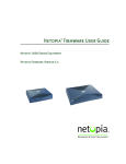
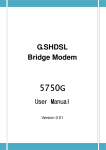
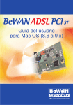
6000 Family IAD
7000 Family IAD
POWER LAN
LINK
LAN WAN
ACT LINK
VOICE DCE
LINK
DCE
ACT
Figure 1–1. NetEngine 6000 and 7000 Integrated Access Devices
NetEngine IAD User Guide
Introduction
Data
Interfaces
2
The data connection through the IAD supports IEEE 802.10-compliant
bridging and routing.
When the IAD is configured for routing, it supports Routing Information
Protocol (RIP) version 1, version 2, or static IP routing. The IAD complies
with RFC-1812 when interfacing with Version 4 IP routers.
The WAN subsystem supports the following interfaces:
u
u
u
NetEngine
6000 IAD
Family
ATM data transport via xDSL and T1/E1 per RFC 1483 or RFC 2364
Frame Relay data transport via xDSL and T1/E1 per RFC 1490
Frame Relay data transport per RFC 1483 with Q.922 frames
The Verilink NetEngineä 6000 IAD family provides a highly
interoperable, cost-effective voice and high-speed data integration solution
that is compatible with industry-leading DSLAM and Voice Gateway
manufacturers. These IADs prioritize voice packets and dynamically
allocate bandwidth between voice and data services.
Features
u
u
u
u
u
u
u
u
u
u
Interoperable with DSLAMs based on Alcatel, Texas Instruments,
MetaLink, and Globespan chip sets. These include Lucent Stinger/
TNT, Nokia Speedlink System, Promatory IMAS, AccessLan
PacketLoop, Accelerated Networks AN-3200, CopperMountain
CopperEdge, and Paradyne GranDSLAM DSLAMs, for example.
Seamless voice and high-speed data integration over xDSL or T1/E1
Supports data rates from 144 Kbps to 2.3 Mbps and customer premise
interfaces including POTS, 10/100BaseT Ethernet, BRI
Compatible with WAN protocols including ATM and Frame Relay
BRI IAD supports ISDN BRI telephone interface
RJ11 POTS interface with Loop Start or Ground Start
Dynamic and static IP routing and bridging capabilities
Firewall support via IP filtering
DHCP and NAT to support IP address management
Management capabilities including Telnet, SNMP and TFTP
IADs in the 6000 family are characterized by different WAN interfaces, and
different voice capacity:
u
u
u
u
NetEngine 6100 IADs—provides WAN access over ADSL, and
telephone support for 4 or 8 voice ports (6100-4 and 6108).
NetEngine 6200-8 IAD—provides WAN access via T1 lines, and
provides 8 voice ports.
NetEngine 6200c IADs—provides WAN access via channelized T1/
E1 lines, and provides 4 or 8 voice ports (6204c and 6208c).
NetEngine 6300 IADs—provides voice services and high-speed
Internet or corporate connectivity over SDSL, and provides 4 or 8 voice
ports (6300-4 and 6300-8).
NetEngine IAD User Guide
Introduction
3
u
u
NetEngine 6500 IADs—provides voice services and high-speed
Internet or corporate connectivity over G.SHDSL, and provides 4 or 8
voice ports (6504 and 6508).
NetEngine 6104i/6504i IADs—provides voice services and highspeed Internet or corporate connectivity over ADSL (6104i) or
G.SHDSL (6504i), plus 4 ISDN Basic Rate Interface (BRI) ports for up
to 8 voice extensions.
Physical and electrical specifications for each IAD are listed in Appendix
C, NetEngine IAD Specifications on page 279.
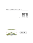
Front Panel Power and Status Indicators
The front panel of the IAD contains several LEDs. These LEDS provide
general information about the operational status of the IAD.
Figure 1–2. 6000 Family Front Panel Indicators
Table 1–1.
6000 Family Front Panel Indicators
LED
Description
POWER
Illuminates when the IAD is powered on.
LAN LINK
Illuminates when there is an operational LAN connection
on the Ethernet port.
LAN ACT
Flashes when there is activity on the Ethernet port.
WAN LINK
Flashes as the IAD is establishing a link, and illuminates
solid when there is a proper connection on the WAN port
and synchronization has been achieved.
VOICE
Illuminates when there is activity on the voice ports.
When connected to a Jetstream Voice Gateway, it
remains lit, and blinks when there is activity.
NetEngine IAD User Guide
Introduction
4
Rear Panel Connectors
On the rear panel (Figure 1–3), the IAD contains several connectors. The
type and position of the WAN and telephone connectors vary by IAD.
Figure 1–3. Typical 6000 Family Back Panel Connectors
POTS Telephone Lines
RJ-11 Jacks
Console (DB-9)
Serial Connector
PWR
Power
Receptacle
CONSOLE
10/100 LAN
LINE 1 LINE 2 LINE 3 LINE 4
LINE 5 LINE 6 LINE 7 LINE 8
WAN
WAN Module
RJ-45 or RJ-48C Jack
Ethernet (RJ-45)
DC Power Adapter
Connects the IAD to any AC outlet of 90-250 volts via an external, 18 volt
power supply.
RS-232 Console Port
Connects the IAD to a PC using a straight through 9-pin serial (DB9 RS232) cable, for the purpose of using a terminal emulator for IAD
configuration and management.
10/100Base-T Ethernet Port
Connects the IAD to the local area network using a CAT-5 straight through
Ethernet cable, or directly to a PC for accessing via Telnet (using a crossover cable, customer-supplied).
WAN Interfaces
Depending on the IAD, WAN interfaces include the following:
u
u
u
u
T1/E1—uses an RJ48 connector for the connection.
G.SHDSL—uses an RJ11 connector for the connection.
SDSL—uses an RJ45 connector for the connection.
ADSL—uses an RJ45 connector for the connection.
Telephone Interfaces
6000 family IADs have varying telephone capacity. These IADs support:
u
4 or 8 analog telephones via RJ11 POTS ports
—or—
u
8 telephone extensions via 4 BRI ISDN S0 ports.
NetEngine IAD User Guide
Introduction
NetEngine
7000 IAD
Family
5
The Verilink NetEngineä 7000 IAD family provides a highly
interoperable, cost-effective broadband solution for voice and high-speed
data integration that is compatible with industry-leading DSLAM and Voice
Gateway manufacturers. These IADs prioritize voice packets and
dynamically allocate bandwidth between voice and data services.
Features
u
u
u
u
u
u
u
u
u
u
Interoperable with DSLAMs based on Alcatel, Texas Instruments,
MetaLink, and Globespan chip sets. These include Lucent Stinger/
TNT, Nokia Speedlink System, Promatory IMAS, AccessLan
PacketLoop, Accelerated Networks AN-3200, Coppermountain
CopperEdge, and Paradyne GranDSLAM DSLAMs, for example.
Seamless voice and high-speed data integration over xDSL or T1/ITE1
Supports data rates from 144 Kbps to 2.3 Mbps and customer premise
interfaces including POTS, 10/100BaseT Ethernet
Compatible with WAN protocols including ATM and Frame Relay
RJ21X POTS interface with Loop Start or Ground Start
Universal Serial Interface supports V.35 and EIA-530
Dynamic and static IP routing and bridging capabilities
Firewall support via IP filtering
DHCP and NAT to support IP address management
Management capabilities including Telnet, SNMP and TFTP
IADs in the 7000 family are characterized by different WAN interfaces and
different voice capacity:
u
u
u
NetEngine 7216 IAD—provides WAN access over T1/E1, and
telephone support for 16 voice ports via RJ21X connector.
NetEngine 7216c IAD—provides WAN access over channelized T1,
and telephone support for 16 voice ports via RJ21X connector.
NetEngine 7316 IAD—provides WAN access over SDSL, and
telephone support for 16 voice ports via RJ21X connector.
Physical and electrical specifications for each IAD are listed in Appendix
C, NetEngine IAD Specifications on page 279.
Front Panel Power and Status Indicators
The front panel of the IAD contains several LEDs. These LEDs provide
general information about the operational status of the IAD.
NetEngine IAD User Guide
Introduction
6
Figure 1–4. 7000 Family IAD Front Panel
Front Panel
NetEngine 7200
POWER
LAN
LINK
LAN
ACT
WAN
LINK
VOICE
DCE
LINK
DCE
ACT
Status Indicators
Table 1–2.
Front Panel LEDs
LED
Description
POWER
Illuminates when the IAD is powered on.
LAN LINK
Illuminates when there is an operational LAN connection
on the Ethernet port.
LAN ACT
Flashes when there is activity on the Ethernet port.
WAN LINK
Flashes as the IAD is establishing a link, and illuminates
solid when there is a proper connection on the DSL WAN
port and synchronization has been achieved.
VOICE
Illuminates when there is activity on the voice ports.
When connected to a Jetstream Voice Gateway, it
remains lit, and blinks when there is activity.
DCE LINK
Illuminates when there is a link between the IAD and
data communications equipment (DCE).
DCE ACT
Illuminates or blinks when there is activity on the DCE
link.
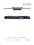
Rear Panel Connectors
On the rear panel, the IAD contains several connectors. The WAN
connectors vary by IAD—both are present, but one has a permanently
attached metal shield to prevent use.
Figure 1–5. 7000 Family IAD Back Panel
,!,-./+
0,* 102
23
.
1+- 4'(5
*++
! .'.
'*
"#6 ! .6
,.,*
.6
",1* 1*.
! "
# # !$ %&
0/
1+
'()
NetEngine IAD User Guide
Introduction
7
AC Power
Connects the IAD to an AC outlet of 108-130 volts via an AC power cord.
10/100Base-T Ethernet Port
Connects the IAD to the local area network using a CAT-5 straight through
Ethernet cable, or directly to a PC for accessing via Telnet (using a crossover cable, customer-supplied).
WAN Interfaces
Depending on the IAD, WAN interfaces include the following:
u
u
T1/E1—uses an RJ48 connector for the connection.
SDSL—uses an RJ45 connector for the connection.
Universal Serial Interface (USI) Port
The USI port is configurable for RS-530 or V.35. When configured as an
RS-530 port, you may use a straight through DB25 serial cable for
connection to your leased line DSU/CSU equipment. When configured for
use as V.35, Black Box Corporation provides a cable (FA058) for
conversion purposes. To convert from RS-530 to RS-449, Black Box
provides a cable EDN57J. By notifying you of their availability, Verilink
neither endorses or recommends these products.
For USI port pinouts when configured as RS-530, V.35 or RS-449, see
Table D–9 on page 291.
RS-232 Console Port
Connects the IAD to a PC, using a straight through 9-pin serial (DB9 RS232) cable for the purpose of using a terminal emulator for configuration
and management.
Telephone Interfaces
Each 7000 family IAD supports 16 analog telephones via an RJ-11 jack.
NetEngine IAD User Guide
Introduction
8
NetEngine IAD User Guide
2. Quick Start Guide
This chapter describes the steps to install, connect, and set the IP address
of the NetEngine IAD. It introduces the menu interface and describes how
to perform basic configuration for common LAN and WAN environments. It
also describes basic operations—resetting the IAD, and logging off.
In many cases, all the information you need to get an IAD up and running
in a customer’s premises is contained in this single chapter.
This chapter contains the following topics:
u
u
u
u
u
u
u
u
u
u
u
Unpacking the IAD (page 10)
Installing the IAD (page 10)
Connecting via Terminal Emulator (page 11)
Resetting the IAD (page 10)
Powering up the IAD (page 12)
Logging on to the IAD (page 12)
Setting the Ethernet port IP address (page 13)
Connecting via Telnet (page 16)
Basic IAD configuration (page 20)
Connecting the LAN, WAN, USI and Telephones (page 20)
Confirming proper setup (page 22)
In most installations, you’ll proceed through these topics in order. If your
situation varies, complete information on installation, connection,
configuration and troubleshooting is contained in the reference chapters
following this chapter.
NOTE
When the IAD prompts you for input, the current value is
displayed in parentheses. To conveniently accept the current
value, just press Enter.
NetEngine IAD User Guide
Quick Start Guide
Unpacking
the IAD
10
Each IAD is packed and shipped in a durable container. If you haven’t
already done so, open the container and unpack the IAD. Carefully
remove the IAD from the package and packing material.
IAD Package Components
Each IAD is shipped with the components listed below. As you unpack
them, note their condition and identity, and compare the list to the packing
list in the package.
u
u
u
u
AC power adapter and cord (6 feet long), or AC power cord
Agency Compliance information sheet
Ethernet cable (straight through), 7 feet long
WAN cable (varies by interface), 7 feet long
If you note any visible damage, or components are missing, notify the
shipping company immediately to make a damage claim. Contact the
company from which the IAD was purchased (Verilink, or an authorized
distributor) to obtain a Return Material Authorization (RMA) for return of
damaged equipment, or to order missing components.
NOTE
Installing
the IAD
We suggest you keep the shipping container and packing
material for future shipping or storage of the unit.
After you unpack the IAD, find a suitable location to install the IAD in the
customer’s premises. Ideal locations include computer equipment room, or
a telephone or wiring closet. You can locate the IAD in an equipment rack,
on a table or shelf, or it may be wall-mounted. Install the IAD in a location
that is generally protected and the IAD will be undisturbed.
AC Power and Uninterruptible Power Supply
The IAD requires access to AC power (NEMA 15-3R). Make sure the IAD
is located within six feet of an AC power outlet. Locate the nearest power
outlet and plug in the supplied AC power adapter or AC power cord. If
there is an uninterruptible power supply on premises, plug the AC power
adapter or cord into that power source.
Ensure that the power cord conveniently and safely reaches the rear panel
of the IAD where the power plug or adapter jack is located.
6000 Family Do not attach the AC power adapter, or power up the unit at
POWER
LAN LINK
LAN ACT
WAN LINK
VOICE
POWER
LAN LINK
LAN ACT
WAN LINK
VOICE
this time.
7000 Family Plug in the power cord, but do not power up the unit
Clearance Requirements
If you install the IAD horizontally, make sure you maintain at least 2 inches
of horizontal distance from other IADs or other electronic equipment, to
ensure adequate ventilation and heat dissipation. If you install the IAD
NetEngine IAD User Guide
Quick Start Guide
11
vertically, ensure at least 3 inches of distance between other IADs or other
equipment.
NOTE
6000 family IADs may be stacked on top of one another,
when mounted horizontally. 7000 family IADs may be rack
mounted.
Wiring Requirements
Make sure that the telephone wiring, LAN and WAN cables reach the IAD
and can be dressed in a manner that is safe for the wiring, does not pull or
create lateral stress on the connectors or ports on the rear of the IAD, and
does not present a trip hazard to personnel working in the vicinity of the
equipment. Do not connect any cables or wiring at this time.
Connect
via
Terminal
Emulator
The IAD is configured and managed from either the console or Ethernet
port. Most network engineers use Telnet to access the IAD via Ethernet.
After you use a terminal emulator program via the console port to set the
IP address, you may continue to use a terminal emulator via the console
port if you choose.
NOTE
After a period of inactivity (three minutes by default), the IAD
automatically terminates console-based and Telnet sessions
to maintain security. To change this value, see Configuring
the Console Timeout Period on page 38.
Before you can connect to the IAD via Telnet, make sure the IP address is
set correctly for this network. To do so, follow the steps, each described in
detail below:
1. Connect the IAD to a PC
2. Log in to the IAD
3. Set the IP address
NOTE
Be sure that the IAD and PC are both powered OFF before
connecting the console cable. If both devices are not turned
off when you connect the cables, you may place the IAD in an
unstable state, and you may need to reset one or both
devices before you can perform configuration tasks.
Connect the IAD to a PC
To connect the IAD to a PC via the console port:
1. Turn off both devices and insert the male connector of a DB9 serial
cable into the console port on the IAD.
2. Insert the female connector of the cable into a serial (COM) port on
your PC.
NOTE
See RS-232 DB-9 Console Port Pin Assignments on page
289 for console port specifications.
NetEngine IAD User Guide
Quick Start Guide
12
Power Up the IAD
1. With the console cable connected, on 6000 family IADs plug the AC
power adapter into the IAD. On 7000 family IADs, turn on the power
switch, located on the back panel. This starts the IAD and it executes
the boot process to begin normal operation.
2. Verify that the Power indicator on the front panel illuminates.
NOTE
As the IAD boots, it sends status messages to the console
port. If you are connected, you will see the boot sequence
progress.
Log in via a Terminal Emulation Program
With a serial cable connected, follow these steps to log in to the IAD:
1. Open a terminal emulation program (Hyperterminal, for example).
2. Select the COM port to which the IAD is connected.
3. Type or select the following settings and save your changes.
Table 2–1.
Terminal Emulator Settings
Setting
Value
Setting
Value
Bits per second
19,200
Stop bits
1
Data bits
8
Flow control
None
Parity
None
Emulation
ANSI or VT100
4. Press Enter. The IAD displays the log in message:
Enter Login ID >
NOTE
If the IAD does not respond, make sure the IAD is powered
up, check the cable and connections, and review the settings.
5. Type the default supervisor level user ID (Supervisor) (or your user
ID if changed) and press Enter. Note that both the user ID and
password are case-sensitive.
Table 2–2 below lists the default user IDs and passwords.
Table 2–2.
Default IAD User IDs and Passwords
Security Level
User ID
Password
User
<enter>
<Enter>
Network
Administrator
NetMan
<Enter>
Supervisor
Supervisor
supervisor
For information on security levels, and user ID and password management
see IAD Security on page 24.
6. The IAD displays the password message:
Enter Password >
NetEngine IAD User Guide
Quick Start Guide
13
7. Type the default password (supervisor, or your password if
different) and press Enter.
8. If log in is not successful, the IAD displays the following message:
Invalid UserID or Password - Try again
Press any key to continue...
9. Press any key, and repeat the log in sequence. If you cannot log in,
call your support provider for assistance.
When you first log in, the IAD displays the Main menu. The menu may
vary, depending on the IAD.
Figure 2–1. Main Menu
*****************************************
Main Menu
*****************************************
1. Reports Menu
2. Configure IP Router
3. Configure Bridge
5. Configure WAN
6. Configure LAN
7. Configure SNMP
8. Configure Login
9. System Utilities
D. Configure DHCP Server
M. Configure Multicast
N. Configure NAT
T. Telephony Clock Recovery
Z. Diagnostics Menu
C. Command Line Interface
R. Reset System
P. Voice Path Configure
E | A | O. CopperCom Call Control
Options E, A and O
vary, depending on the
voice gateway selected
in the Voice Path
Configure command.
Setting the Ethernet Port IP Address
Before you configure the Ethernet IP address, you should know the IP
address and subnet mask that is to be assigned to this port. It may be
displayed on the work order, or you may obtain or determine the
appropriate IP address by consulting with the network administrator.
The IAD is shipped with a null IP address and subnet mask. To configure a
port IP address:
1. On the Main menu, type 2 to select Configure IP Router.
2. The IAD displays the Router Configuration menu.
NetEngine IAD User Guide
Quick Start Guide
14
Figure 2–2. Router Configuration Menu
*****************************************
Router Configuration Menu
*****************************************
C.
U.
M.
S.
R.
V.
P.
N.
H.
L.
T.
F.
Q.
B.
D.
Configure Port IP Address
Unconfigure Port IP Address
Configure Port Max Transmission Unit
Add/Remove a Static Route
Enable/Disable RIP
Configure RIP Version by Port
Configure RIP Poisoned Reverse by Port
Configure DNS Client
Configure DHCP Client
Configure DHCP Relay
Configure Telnet Server Port
Configure IP Filtering
Configure IP Header Compression
Configure LAN IP Broadcast Destination
Display Route Table
Type C to select Configure Port IP Address.
3. The IAD displays the following menu (sample—all options shown). The
interfaces that display depend on the specific IAD:
Figure 2–3. Router Configuration Menu
Available Interfaces:
1.
1.
1.
1.
2.
0.
G2237 xDSL
G7070 ADSL ATU-R
T1/E1
SDSL
10/100BaseT Ethernet
(Abort)
Type 2 to set the IP address for the Ethernet port.
4. If the IP address is configured for the port, the IAD displays information
about the interface and a prompt:
IP interfaces on port 2:
ID
0
IPAddr
92.1.1.90
IPMask
255.255.255.0
Priority
NORMAL
Enter connection to configure:
Type the ID number of the connection that you want to configure (in
this case, 0) and press Enter.
5. Type the new IP address, and press Enter (or press Enter to retain the
current IP address).
NetEngine IAD User Guide
Quick Start Guide
15
6. The IAD displays the following information:
Current subnet mask = 0.0.0.0
Enter new subnet mask for this interface:
Type the new subnet mask (usually 255.255.255.0) and press Enter.
7. The IAD displays the following instructions:
Select priority Normal/High [N/H] (N):
Give the interface normal priority—type N or press Enter.
8. Type Y or Enter to save the new IP address and subnet mask.
9. To exit, press Escape, then type Y to terminate the session.
10. Quit the terminal emulator program.
11. Reset the IAD (following) for the new IP address to be in effect.
NOTE
When you configure the IAD, you must restart the IAD each
time you change the settings for those changes to take effect.
You may make several configuration changes before
resetting if you choose, for efficiency.
If you plan to use Telnet for configuration tasks, this is a good time to
disconnect the serial cable from the PC and IAD.
Resetting
the IAD
Many configuration tasks require that you reset (or restart) the IAD before
the new settings or configuration will take effect. When you use the menu
interface (or the Command Line Interface on page 243) to make changes,
or change the physical characteristics of the IAD (such as changing the
Ethernet port MAC address), you must reset the IAD.
The IAD stores all configuration settings in memory. When it restarts, it
loads the last configuration saved before it was powered down or
restarted. When restarting is required, it will be included as a step in the
configuration process.
You can reset the IAD in two ways.
To reset the IAD from the menu:
1. On the Main menu, type R to select Reset System.
The IAD displays the following instructions:
Press R to Reset now->
2. Type R again. This resets and starts the IAD with your new settings.
3. To log in again, enter your user ID and password.
To reset the IAD manually:
On a 6000 family IAD, unplug the power adapter from the IAD and then
plug it back into the IAD. On a 7000 family IAD, turn the IAD off, then back
on. Be sure to complete your task and return to the Main menu before
restarting the IAD in this manner.
CAUTION
Resetting the IAD terminates all telephone calls and
computer sessions in progress. You should ensure that there
no services are being rendered before resetting the IAD.
NetEngine IAD User Guide
Quick Start Guide
Connecting
via Telnet
16
To manage the IAD via the LAN (or Intranet), you must set an IP address
for the Ethernet port before you can use Telnet to access the IAD.
NOTES
Although you can also access the IAD using Telnet via the
WAN (provided a management DLCI or PVC is configured
along with a WAN IP address), this section describes
connecting via the LAN. For information about setting the IP
address of the WAN port, see Chapter 6, WAN Configuration
on page 51.
If you configure a RADIUS server, you must use a RADIUSauthenticated User ID/password for Telnet access. If the
RADIUS server or the connection to the RADIUS server goes
down, Telnet access will not work. For information about
configuring a RADIUS server, see RADIUS Server Settings
on page 27.
Running Telnet
Before you use Telnet to log in to the IAD, make sure that the IAD and
your PC are connected to the same network via straight-through Ethernet
cables (or directly connected via a cross-over cable), and you know the IP
address of the IAD. Both devices must be on the same subnet.
Follow these steps to log in:
1. Run Telnet on your PC.
2. Type the IP address of the Ethernet port (page 13), click Connect and
then press Enter to gain the attention of the IAD.
3. The IAD responds by displaying the log in message:
Enter Login ID >
4. Type your user ID and press Enter.
NOTE
After a period of inactivity (three minutes by default), the IAD
automatically terminates console-based and Telnet sessions
to maintain security. To change this value, see Configuring
the Console Timeout Period on page 38.
Default user IDs and passwords are listed in Table 2–2 on page 12. For
information on security levels, and user ID and password management
see IAD Security on page 24.
5. The IAD displays the password message:
Enter Password >
NetEngine IAD User Guide
Quick Start Guide
17
4.Type your password and press Enter to display the Main menu.
*****************************************
Main Menu
*****************************************
1.
2.
3.
5.
6.
7.
8.
9.
D.
N.
T.
Z.
C.
R.
P.
NOTE
Using the
Menu
Interface
Reports Menu
Configure IP Router
Configure Bridge
Configure WAN
Configure LAN
Configure SNMP
Configure Login
System Utilities
Configure DHCP Server
Configure NAT
Telephony Clock Recovery
Diagnostics Menu
Command Line Interface
Reset System
Voice Path Configure
The user ID and password transmit as clear text, which may
be captured by unauthorized individuals. If you are concerned
with network security, you may not want to use Telnet to
configure the IAD.
The NetEngine IAD provides an ANSI-terminal-based menu interface for
system configuration and monitoring. When you log in, the IAD displays
the Main menu.
The commands displayed in some menus (including the Main menu) differ,
depending on the level at which you log in. Figure 2–4 on page 18 displays
the Main menu when you log in at the Supervisor security level. Figure 2–
5 on page 18 displays the Main menu when you log in as Network
Administrator, and Figure 2–6 on page 18 displays the Main menu when
you log in as User.
NetEngine IAD User Guide
Quick Start Guide
18
Figure 2–4. Main Menu for Supervisor
*****************************************
Main Menu
*****************************************
1.
2.
3.
5.
6.
7.
8.
9.
D.
M.
N.
T.
Z.
C.
R.
P.
E.
O.
Reports Menu
Configure IP Router
Configure Bridge
Configure WAN
Configure LAN
Configure SNMP
Configure Login
System Utilities
Configure DHCP Server
Options E, A and O vary,
Configure Multicast
depending on the Voice
Configure NAT
Gateway selected in the
Telephony Clock Recovery
Voice Path Configure
Diagnostics Menu
command. These options
Command Line Interface
only display when logged
Reset System
on as Supervisor.
Voice Path Configure
Toggle CMCP Debugging
Manage MGCP Embedded Client Selection
Figure 2–5. Main Menu for Network Administrator
*****************************************
*
Main Menu
*
*****************************************
1.
2.
3.
7.
8.
9.
D.
M.
N.
Z.
R.
Reports Menu
Configure IP Router
Configure Bridge
Configure SNMP
Configure Login
System Utilities
Configure DHCP Server
Configure Multicast
Configure NAT
Diagnostics Menu
Reset System
Figure 2–6. Main Menu for User
*****************************************
Main Menu
*****************************************
1. Reports Menu
8. Configure Login
NetEngine IAD User Guide
Quick Start Guide
19
Navigating the IAD Menu Interface
Menus in the IAD configuration system are arranged hierarchically. That is,
you select single-key options to navigate down to display specialized
menus and specific tasks, and press the Escape key successively to
return back to menus higher in the interface.
The specific menus, submenus and commands that display depend on the
interfaces for the specific IAD, the options configured and the security level
that you use to log in.
To select a menu item, just type the option displayed to the left of the item.
Although character options are displayed in upper case, the IAD accepts
both upper and lower case options. It is not necessary to press Enter after
typing the selection to execute it—the IAD immediately responds with a
request for input or another menu for more options.
For a hierarchical map of the Main menu, its menus and commands, see
Appendix A, Menu Map on page 275.
Entering Settings and Values
When the IAD requests input for a setting or configuration value, type it at
the prompt. Press the Enter key to terminate the input and proceed to the
next step.
The IAD responds with error messages if a value is incorrect, or it displays
the current menu so you can continue with related tasks.
Using Default or Current Values
The IAD displays a default or current value in parentheses immediately to
the right of each message, just to the left of the command prompt. To
accept this value, just press the Enter key.
For example, when the following message displays:
Enter a new subnet mask for this interface:
(255.255.255.0) -)
You may press Enter to cause the IAD to set 255.255.255.0 as the
subnet mask value. Using the Enter key to skip through default or current
values often speeds the process of proceeding through a family of input
steps, to quickly get to the input step where you want to change a value.
NetEngine IAD User Guide
Quick Start Guide
20
Exiting the Menu Interface
To exit the menu interface, return to the Main menu using the Escape key,
and press Escape one more time. The IAD asks you to confirm—press Y
to exit (or press Return to accept the default value (N) to cancel the exit).
After exiting, you can quit the terminal emulator or Telnet application. If
you made changes to the configuration that require resetting the IAD, be
sure to do so before exiting.
Basic IAD
Configuration
Connecting
LAN, WAN,
USI and
Telephones
Each IAD has a default configuration when it is shipped from the factory.
At a minimum, you should view the configuration and check the following
settings for probable update for each customer installation:
1. Configure the LAN IP address, if not already completed (page 13)
2. Configure each of the WAN options and the DSLAM profile (WAN
Configuration on page 51)
3. Create and configure at least one DLCI (page 93) or PVC (page 81) for
data traffic and set the WAN IP address (WAN Configuration on page
51.)
4. Configure static or default route or enable bridging for all data traffic
5. Create and configure a DCLI (page 93) or PVC (page 81) for voice
where required and select appropriate voice gateway settings.
6. Reset the IAD (page 15) to enable all configuration changes.
In this section, you’ll connect the IAD to the computer and telephone
systems the IAD is intended to support.
Before proceeding, make sure that you have an appropriate serial cable
for your PC, identify the LAN switching equipment where you’ll connect the
IAD, identify the telephone cables, and verify that WAN service is installed,
and configured by the service provider.
When you’ve completed this section, reset the IAD so it can synchronize
these physical connections.
Ethernet LAN Connection
The Ethernet LAN port on the rear of the IAD is an RJ45 jack for 10/
100Base-T Ethernet cables. If the IAD is intended to act as an Internet
gateway for the LAN in the customer’s premises, connect the IAD to the
switch, hub or router using an Ethernet straight-through cable.
NOTE
To temporarily connect the IAD directly to a PC for Telnet
configuration (without going through a hub or router), be sure
to use an Ethernet cross-over cable (customer-supplied).
WAN Connections
WAN connections vary, based on the WAN interface on your IAD. Identify
the WAN interface on your IAD, and proceed to the appropriate section.
NetEngine IAD User Guide
Quick Start Guide
21
Making G.SHDSL Connections
G.SHDSL-equipped IADs use an RJ11 connector on the rear panel for
WAN connection. To make the connection, plug the WAN cable into the
RJ11 WAN connector. Table D–7 on page 290 lists the G.SHDSL
connector pinouts.
Making SDSL or ADSL Connections
SDSL- and ADSL-equipped IADs use an RJ45 connector on the rear panel
for WAN connection. To make the connection, plug the xDSL cable into the
RJ45 WAN connector. Table D–6 on page 290 lists the RJ45 WAN pinouts.
Making T1/E1 Connections
T1/E1-equipped IADs use an RJ48 connector on the IAD rear panel for
WAN connection. To make the connection, plug the cable from the ATM
network into the RJ48 WAN connector. Table D–8 on page 291 lists the
pinouts for the T1/E1 connector.
USI Connection (7200, 7300)
7300
POWER
LAN LINK
LAN ACT
WAN LINK
VOICE
7200
7300
7000 family IADs have a Universal Serial Interface (USI) port,
configurable for V.35 or EIA-530 (page 37).
If your IAD is equipped with a USI port, you may connect it now. Located
on the rear panel, the port uses a shielded, DB25 connector. The
connector is DCE—data is transmitted on the receive pin and received on
the transmit pin.
The V.35 or EIA-530 interfaces use different voltage levels. You must
supply the appropriate cable for each interface. Table D–9 on page 291
lists the USI port pinouts and signal specifications.
Telephone Connections
6000 family IADs provide 4 or 8 RJ11 ports for POTS devices, or ISDN
connectors for telephone service. 7000 family IADs provide an RJ21X
Amphenol-style connector for connecting up to 16 telephone devices.
These devices may be POTS telephones, modems, FAX machines, or
other POTS-compatible devices.
Making RJ11 Connections (6000 family)
The RJ11 POTS port pinouts are telco standard (RJ11 POTS Port Pin
Assignments on page 289). Connect each telephone device to the RJ11
jacks using 26AWG telephone cord or better (user provided).
Making ISDN Connections (6104i, 6504i)
The RJ45 BRI IDSN S0 ports are telco standard (RJ45 BRI ISDN S0 Port
Pin Assignments on page 289). Connect each ISDN cable from the ISDN
terminal equipment to the S0 ports on the back of the IAD using 4-wire
cable. The ports provide PS1 and PS2 powering for ISDN telephones, at
10 power consumption units per port.
NetEngine IAD User Guide
Quick Start Guide
22
Making RJ21X Connections (7000 family)
The pin assignments for the RJ21X connector are telco standard. Connect
telephone devices from an RJ11 jack field, or a punch down block. Each
line provides a two-wire loop or groundstart connection. To perform the
connection, use a customer-provided cable terminated at one end with an
RJ21X connector. After connecting each color-coded wire pair to the
corresponding telephone connection on the jack field or punchdown block,
connect the RJ21X connector to the connector on the IAD rear panel.
Confirming
Proper
Setup
When you have completed the tasks in this chapter, reset the IAD and test
your configuration.
Reset the IAD
Reset the IAD (page 15) to synchronize the physical connections.
Verify Normal Power Up and Operation
Finally, to test your configuration for proper data and voice operation,
perform the operational test (Operational Test on page 272).
NetEngine IAD User Guide
3. Administration
This chapter describes how to control security to your IAD, validate users
using a RADIUS server, configure SNMP via IP or EOC, upgrade IAD
software, and perform other general and utility-oriented tasks.
This chapter includes these topics:
u
u
u
u
u
u
u
u
u
IAD security—setting user IDs and passwords (page 24)
Using a RADIUS server for authentication (page 27)
Configuring SNMP (page 29)
Upgrading IAD system software (page 33)
Upgrading ACOS (page 46)
Configuring the IAD for LAN connection (page 35)
Using system utilities (page 24)
Setting derived timing options (page 48)
Resetting the IAD (page 15)
NOTE
Polycom, Inc.
When the IAD prompts you for input, the current value is
displayed in parentheses. To conveniently accept the current
value, just press Enter.
NetEngine IAD User Guide
Administration
IAD
Security
24
To maintain IAD security, the IAD provides multi-level login access using a
single user ID and password, which you can set at the following levels:
u
u
u
User
Network Administrator
Supervisor
The user ID at the User security level may be modified, but the user ID at
the Network Administrator and Supervisor level may not be modified.
The password for each security level may be changed. Although you may
use the same password for all security levels, Verilink recommends that
you use a different one for each level. Table 3–2 lists the privileges
available at each security level.
Table 3–1.
Security Level Privileges
Security level
Privileges
Supervisor
This user level is the highest level. Users who
log in as Supervisor have full access to all IAD
features (menu and command line interface,
including changing User security level user ID
and any level passwords, plus complete IAD
configuration capability.
Network Administrator
This user may perform tasks that alter the
network settings of the IAD, plus has access to
all of the data networking configuration menus,
and can update routing and bridging
information and status.
This user can change this level password, and
the User level user ID and password, and has
access to all display-only menus.
This user may not modify WAN or LAN
settings, alter derived timing, use command
line interface, or modify voicepath settings.
User
This user has access to display-only menus,
and may view the current configuration,
interface and media statistics, routing and
bridging information and status. This user may
change this level user ID and password. This
user may not make or save any changes to the
configuration of the IAD.
To maintain IAD security, a user with Supervisor privileges should modify
the User security level user ID and passwords for both User level and
Network Administrator level prior to placing the IAD into production.
NetEngine IAD User Guide
Administration
25
Table 3–2 lists the default values for the user IDs and passwords:
Table 3–2.
Default User IDs and Passwords
Security Level
User ID
Password
User
<Enter>
<Enter>
Network
Administrator
NetMan
<Enter>
Supervisor
Supervisor
supervisor
The user ID and password may contain up to 17 alphanumeric characters.
These values are case sensitive; spaces and punctuation characters are
not allowed.
NOTE
The IAD can only store one user ID and password at each
security level.
Changing a Password
To change a password at any security level, you must sign on at or above
the security level you’re changing and follow these steps:
1. On the Main menu, type 8 (Configure Login) to display the Password
Configuration menu.
Figure 3–1. Password Configuration Menu
*******************************************
Password Configuration Menu
*******************************************
1. Change User ID
2. Change User Password
3. Change NetMan Password
4. Change Supervisor Password
5. Change Primary RADIUS Server Address
6. Change Primary RADIUS Encryption Secret
7. Change Secondary RADIUS Server Address
8. Change Secondary RADIUS Encryption Secret
9. Display RADIUS Configuration
2. Type 2, 3, or 4 to change the password for the selected level.
3. Enter the password for the current level.
4. Enter the new password after the prompt, or press Enter to enter a null
password.
5. Enter the new password (or Enter) again, to confirm the change.
The IAD immediately updates the password. The next time you log in at
that level, the new password will be in effect.
NOTE
You cannot use the Escape key to exit the password update
command. To exit, deliberately enter an incorrect password
at the confirmation step, or reset the IAD.
NetEngine IAD User Guide
Administration
26
Changing the User Level User ID
To change the user ID for the User security level (the only security level
that allows the user ID to be changed), follow these steps:
1. On the Main menu, type 8 (Configure Login) to display the Password
Configuration menu.
2. Type 1 to change the user ID for the User security level.
Enter new User ID (up to 17 characters) >
3. Type the new User ID and press Enter. The IAD informs you that the
user ID has been updated.
4. Reset the IAD (page 15).
Including User ID and Passwords in Config Files
If you create master configuration files for distribution to multiple IADs, you
may include the userid and passwords directly in the configuration file to
reduce configuration tasks.
NOTE
When the user ID and passwords are stored in a
configuration file, the IAD saves the configuration file
immediately upon rebooting, without requiring the log on
process. The userid and passwords are stripped from the
configuration file before saving to prevent a security risk.
Using a text editor, update the config file by adding the following attributes
in the [user] category:
userid={string}
password={string}
netman-password={string}
support-password={string}
The password parameter is for user level access; netman-password is for
network administrator level access; and support-password is for
supervisor level access.
NetEngine IAD User Guide
Administration
RADIUS
Server
Settings
27
You can use a RADIUS server to determine the validity of unknown user
ID/password pairs in your IAD. To use a RADIUS server, set the following
options:
u
u
u
Change the primary or secondary RADIUS Server Address
Change the primary or secondary RADIUS Encryption Secret
Display RADIUS Configuration
NOTE
Verilink does not provide a RADIUS server. You must provide
a RADIUS server to use this feature. For more information on
RADIUS servers, see RFC 2865.
If you configure a RADIUS server, the IAD must be able to successfully
connect to the RADIUS Server. This requires WAN configuration, IP
configuration, static or default routes and other configurations for your
network. Additionally, you must use a RADIUS-authenticated user ID/
password for Telnet access. If the RADIUS server becomes inoperative,
Telnet access will not work.
Changing the RADIUS Server Address
To change the primary or secondary RADIUS server address:
1. On the Main menu, type 8 (Configure Login) to display the Password
Configuration menu (page 25).
2. Type 5 to select Change Primary RADIUS Server Address or Type 7
to select Change Secondary RADIUS Server Address.
The IAD displays the following message:
Primary/Secondary RADIUS Server is currently:
Enter new Primary/Secondary RADIUS Server as either
an IP address or name >
3. Type the IP address in one of the following formats and press Enter:
IP address
Fully-qualified host and domain names
(for example: radius.Verilink.com—maximum 42 bytes)
u
u
NOTE
If you enter host and domain names, you must configure the
IAD as a DNS client (page 114).
4. Reset the IAD (page 15).
Changing the RADIUS Encryption Secret
To change the primary or secondary RADIUS encryption key:
1. On the Main menu, type 8 (Configure Login) to display the Password
Configuration menu (page 25).
2. Type 6 to select Change Primary RADIUS Encryption Secret or type 8
to change Secondary RADIUS Encryption Secret.
The IAD displays the following message:
Primary/Secondary RADIUS Encryption Secret is
currently:
Enter new Primary/Secondary RADIUS Encryption Secret
NetEngine IAD User Guide
Administration
28
3. Type the new encryption key and press Enter.
4. Reset the IAD (page 15).
Displaying the RADIUS Configuration
To display the current RADIUS server configuration:
1. On the Main menu, select Configure Login to display the Password
Configuration menu (page 25).
2. Type 9 to select Display RADIUS Configuration.
The IAD displays the following information:
Primary RADIUS Server:
Primary RADIUS Secret:
Secondary RADIUS Server:
Secondary RADIUS Secret:
NetEngine IAD User Guide
Administration
Setting Up
SNMP
29
You can enable SNMP over IP and/or EOC (when the voice gateway is
AAL2/LES CAS or ELCP). By default, the IAD is configured with SNMP
disabled. When SNMP is enabled and the settings are configured, you can
use SNMP to remotely manage the IAD by getting and setting IAD values,
and monitoring IAD events.
The IAD supports the following SNMP settings:
u
u
u
u
u
u
System Contact
System Name
System Location
SNMP Community
SNMP Trap Host IP Address
af-vmoa-0172 (AAL2/LES)
The following SNMP traps are supported:
u
u
u
System reset
Attempts to access SNMP with an invalid community name
Starting and stopping TFTP within SNMP
The IAD supports MIBs for RFCs 1213, 1317, 1406, 1493, 1463 as well as
af-vmoa-0172 (AAL2/LES MIB).
Using the SNMP Configuration Menu
To display the SNMP Configuration menu, type 7 on the Main menu. The
following SNMP tasks are accessed from this menu:
Figure 3–2. SNMP Configuration Menu
*****************************************
SNMP Configuration Menu
*****************************************
E.
F.
A.
B.
P.
N.
L.
C.
T.
U.
D.
Enable/Disable SNMP via IP
Enable/Disable SNMP via EOC
Enable SNMP via both IP and EOC
Disable SNMP via both IP and EOC
Configure System Contact
Configure System Name
Configure System Location
Configure SNMP Community
Configure SNMP Trap Host IP Address
Enable/Disable SNMP Traps via EOC
Configure Restart Trap Max Delay
When you are done updating SNMP settings, you must reset the IAD for
the new settings to take effect.
NOTE
The strings you enter in SNMP are not case sensitive.
NetEngine IAD User Guide
Administration
30
Enabling and Disabling SNMP via IP
Type E to enable or disable SNMP via IP:
1. The IAD displays the current status of SNMP and a prompt:
SNMP via IP is currently DISABLED
To enable SNMP, type E. To disable SNMP, type D.
2. The IAD saves the configuration (if changed). Continue with other
SNMP settings, or press Escape to return to the Main menu.
3. Reset the IAD (page 15) for changes to take effect.
Enabling and Disabling SNMP via EOC
Type F to enable or disable SNMP via EOC:
1. The IAD displays the current status of SNMP and a prompt:
SNMP via EOC is currently DISABLED
To enable SNMP, type E. To disable SNMP, type D.
2. The IAD saves the configuration (if changed). Continue with other
SNMP settings, or press Escape to return to the Main menu.
3. Reset the IAD (page 15) for changes to take effect.
Enabling SNMP via IP and EOC
Type A to enable SNMP via IP and EOC.
The IAD saves the configuration. Continue with other SNMP settings, or
press Escape to return to the Main menu.
Reset the IAD (page 15) for changes to take effect.
Disabling SNMP via IP and EOC
Type B to disable SNMP via IP and EOC.
The IAD saves the configuration. Continue with other SNMP settings, or
press Escape to return to the Main menu.
Reset the IAD (page 15) for changes to take effect.
Configuring the System Contact
Type P to configure system contact (up to 39 alphanumeric characters):
1. The IAD displays the current system contact and prompt:
System Contact is currently: Verilink
Enter new System Contact >
Type the name of the new contact person or department and press
Enter.
2. The IAD save the configuration. Continue with other SNMP settings, or
press Escape to return to the Main menu.
3. Reset the IAD (page 15).
NetEngine IAD User Guide
Administration
31
Configuring the System Name
Type N to configure the system name (up to 39 alphanumeric characters):
1. The IAD displays the current system name and prompt:
System Description is currently:
Enter new System Description >
Type the new system name and press Enter.
2. The IAD saves the configuration. Continue with other SNMP settings,
or press Escape to return to the Main menu.
3. Reset the IAD (page 15).
Configuring the System Location
Type L to configure the system location (up to 39 alphanumeric
characters):
1. The IAD displays the current system location and prompt:
System Location is currently:
Enter new System Location >
Type the name of the new server location and press Enter.
2. The IAD saves the configuration. Continue with other SNMP settings,
or press Escape to return to the Main menu.
3. Reset the IAD (page 15) for changes to take effect.
Configuring the System Community
The value that you set must match the write community name of the
SNMP host to enable the SNMP Set operation. If you enable SNMP and
the read-write Community Name is null, SNMP enters read-only mode with
a community name of “public”.
Type C to select Configure System Location.
1. The IAD displays the current community name and prompts you to
enter a new name:
SNMP Community is currently:
Enter new SNMP Community >
Type the name of the SNMP community to which your system belongs
and press Enter.
2. The IAD saves the configuration. Continue with other SNMP settings,
or press Escape to return to the Main menu.
3. Reset the IAD (page 15) for changes to take effect.
Configuring the SNMP Trap Host IP Address
Type T to select Select Configure SNMP Trap Host IP Address of the
system setup for trap operations:
1. The IAD displays the current IP address and prompt:
Current SNMP Trap Host IP Address = 0.0.0.0
Enter new SNMP Trap Host IP address:
Type the IP address and press Enter.
2. The IAD saves the configuration. Continue with other SNMP settings,
or press Escape to return to the Main menu.
3. Reset the IAD (page 15) for changes to take effect.
NetEngine IAD User Guide
Administration
32
Enabling or Disabling SNMP Traps via EOC
Type U to enable or disable SNMP traps via EOC:
1. The IAD displays the current status and prompt:
SNMP traps sent via EOC are currently DISABLED
To enable traps via EOC, type E. To disable them, type D.
2. The IAD saves the configuration. Continue with other SNMP settings,
or press Escape to return to the Main menu.
3. Reset the IAD (page 15) for changes to take effect.
Configuring Restart Trap Maximum Delay
Type D to configure the restart trap maximum delay time:
1. The IAD displays the prompt:
Enter SNMP Restart Trap Maximum Delay Time in
Seconds (0..600): (0)
2. Type the new value in seconds and press Enter.
3. The IAD saves the configuration. Continue with other SNMP settings,
or press Escape to return to the Main menu.
4. Reset the IAD (page 15) for changes to take effect.
NetEngine IAD User Guide
Administration
Upgrading
the System
33
Periodically, Verilink may provide new software that you will download to
the IAD to upgrade the system. You must use TFTP to perform the file
transfer when upgrading the entire system.
NOTE
Some gateways directly support file transfer as a means of
upgrading IADs. For information, refer to the Voice Gateway
manufacturer’s operating manual.
To use TFTP, you must configure both the IAD and the computer that
contains the TFTP Server program, a program that you license separately.
Using TFTP Servers via LAN or WAN
Before the IAD can access a LAN or Intranet-based TFTP server, you
must configure the IP address of the Ethernet port (page 13) on the same
subnet as your TFTP server, and the IAD must be connected to the LAN.
To access a WAN-based server, you must configure the T1/E1 or xDSL
Interface with a management DLCI or PVC and a WAN IP address. For
information about setting the IP address of the WAN port, see Chapter 6,
WAN Configuration on page 51.
Copying the Source Files
Typically, you will receive two ZIP files (a core ZIP file and an application
ZIP file) for each upgrade.
First, extract each file into a single directory on your PC. Then, set the
directory as the path that the TFTP Server will use to send files to the IAD
(often identified as upload/download or outbound directory).
Upgrading via TFTP
If your TFTP Server is not running, start it now and note the IP address of
the computer it is running on. To upgrade the IAD software:
1. On the Main menu, type 9 to display the Utilities menu:
Figure 3–3. Utilities Menu
*****************************************
Utilities Menu
*******************************************
P.
T.
Z.
V.
R.
D.
W.
E.
A.
Ping Utility
Trace Route
Configure Console Baud Rate
Configure Console Timeout
Hard Reset or Reload ACOS from FLASH
Set System Default
Save System Settings as Defaults
Display Event Log
Clear "Last Reset Reason"
F. File System Menu
G. Debug Menu
X. File Transfer Menu
NetEngine IAD User Guide
Administration
34
2. Type X to display the File Transfer menu.
Figure 3–4. File Transfer Menu
*******************************************
File Transfer Menu
*******************************************
B. Load Boot ROM
O. Update ACOS [acos.bin]
X. Update Entire System
A. File Transfer Utilities
3. Type X to update the entire system (you must use TFTP).
Respond by typing Y to continue.
4. The IAD displays the following:
**** Download using TFTP ****
Enter ip address of TFTP server.
(98.121.1.167) ->
5. Type the IP address of the TFTP Server and press Enter.
As file transfer progresses, the IAD reports the status of each file being
copied. Two files—acos.bin and boot.bin—will only be copied if they match
the platform, to guard against loading incorrect system files onto an IAD.
NOTE
If the IAD cannot locate the first file to download (typically
release.dat), the update will fail. Make sure you have
assigned a valid IP address and subnet mask, and you’re on
the same subnet as the TFTP Server. Use the Ping command
to successfully ping the IAD and try again.
Upon completion, the IAD reports the success or failure of these files
specifically, and then reports the completion of file transfer and resets.
NOTE
For more information, refer to “Upgrading Imbedded Software
on an IAD with TFTP” from Verilink.
Verifying the Upgrade
To verify that the files downloaded successfully, observe the boot
sequence. The IAD displays the software version in the Verilink banner:
****************************************************
RTOS start sequence
****************************************************
Enter "i" to Inhibit Application Launching only
Enter "I" to additionally Inhibit Initialization (minimal startup)
****************************************************
Verilink
<=> NE6200-8 NetEngine IAD
v3.5.0
<=>
Nov 19 2002
15:33:52
(C) 1998-2002 by Verilink, Inc.
****************************************************
You can also display the current configuration (page 203) to validate the
firmware version.
NetEngine IAD User Guide
Administration
Setting up
Your LAN
Connection
35
The IAD LAN port may be set for full duplex Ethernet operation if your IAD
is set up as a router. Full duplex mode allows simultaneous transmission
and receipt of Ethernet packets.
On the Main menu, type 6 (Configure LAN) to display the LAN
Configuration menu.
Figure 3–5. LAN Configuration Menu
*******************************************
LAN Configuration Menu
*******************************************
1. 10 Mbps Full Duplex
2. 10 Mbps Half Duplex
3. 100 Mbps Full Duplex
4. 100 Mbps Half Duplex
5. Auto Negotiate the Speed, Full Duplex
6. Auto Negotiate the Speed, Half Duplex
7. Auto Negotiate Speed & Full/Half Duplex Mode
8. Display MII & FEC Registers
Selecting the Connection
If more than one connection is defined, the IAD prompts you to specify the
port number. Type the number of the port, select enable or disable and
press Enter.
Establishing LAN Speed and Duplex Mode
1. Type the option number of the speed and duplex mode.
2. The IAD saves the configuration. Press Escape to return to the Main
menu.
3. Reset the IAD (page 15) for changes to take effect.
NOTE
Full duplex Ethernet operation is controlled by the switch. If
the switch is set to full duplex, you may enable it in the IAD. If
you enable full duplex Ethernet in the IAD when the switch is
operating in normal half duplex mode, your IAD will not
communicate on the LAN.
You can display the current LAN settings using the Display Current
Configuration command in the Reports menu (page 203).
NetEngine IAD User Guide
Administration
Using
System
Utilities
36
The Utilities menu contains utility commands, and several menus to
upgrade ACOS software and support ACOS application development.
To display the Utilities menu, type 9 on the Main menu. 7000 family IADs
display a menu with option U, the USI port command:
Figure 3–6. Utilities Menu
*******************************************
Utilities Menu
*******************************************
P.
T.
U.
Z.
V.
R.
D.
W.
E.
A.
F.
G.
X.
Ping Utility
Trace Route
Make a USI Module a UART port
Configure Console Baud Rate
Configure Console Timeout
Hard Reset or Reload ACOS from FLASH
Set System Default
Save System Settings as Defaults
Display Event Log
Clear "Last Reset Reason"
File System Men
Debug Menu
File Transfer Menu
To perform a task, type the option and proceed to the appropriate section.
Pinging Network Devices
To check for a device on a network, follow these instructions:
1. Type P on the Utilities menu.
To set up Ping to run, supply the following information:
1. Type the IP address or complete host name. If you enter a host name,
you must enter the domain name with the host name. For example,
mycomputer.mydomain.com.
2. Type the ping packet size.
3. Type the number of times to ping (0 causes Ping to run until you press
Escape).
The IAD displays the following report:
Pinging: 91.1.1.217
Size: 32 bytes...
Ping Number 1 of 1 (Esc to quit)
Reply from: 91.1.1.217
Size: 32 bytes
Time: < 5 mS
**** Ping Summary ****
Packets Sent
: 1
Packets Received : 1
Packets Lost
: 0
Average Ping Time : < 5 ms
NetEngine IAD User Guide
Administration
37
Using Trace Route
Use Trace Route to trace the network route to a specified host. To run
Trace Route, follow these steps:
1. Type X on the Utilities menu and press Enter.
2. Type the IP address or host name to trace and press Enter. If you enter
a host name, you must enter the domain name with the host name. For
example, mycomputer.mydomain.com.
The IAD displays each hop, as shown in the following sample report:
Trace Route Results to 91.1.1.1
1
5ms
91.1.1.1
Setting up the USI Port
7000
POWER
LAN LINK
LAN ACT
WAN LINK
The USI port is available only on IADs in the 7000 family.
VOICE
To set up the USI port, follow these steps:
1. Type U on the Utilities menu and press Enter.
2. The IAD displays the following:
Enter 1 to enable a USI module as a uart interface
on slot 1
Enter 0 to make a USI module a RS530 interface on
any slot
->(current=0)
3. Type 1 to select V.35. Type 0 to select RS-530.
4. Reset the IAD (page 15) to use the new USI settings. Voltage levels for
V.35 and RS-530 are different. Be sure to use the appropriate cable for
the protocol you choose.
Configuring the Console Baud Rate
To set the console port baud rate (for connecting to Hyperterminal via a
serial cable), follow these steps:
1. Type Z on the Utilities menu to display the following menu:
Current Console Baud Rate is: 19200
Enter New Console Baud Rate
0. Unset (use Default)
1. 9600
2. 19200
3. 38400
4. 57600
5. 115200
2. Type 0 to reset the baud rate to the default (19200 bps), or select a
specific baud rate and press Enter.
3. Reset the IAD (page 15) to use the new console port settings. Be sure
the terminal settings are the same as the console port settings.
NetEngine IAD User Guide
Administration
38
Configuring the Console Timeout Period
To maintain security, you can set the amount of time a console or Telnet
session remains alive before termination due to inactivity. To set the
timeout period, follow these steps:
1. Type V on the Utilities menu to display this message and prompt:
Console timeout is currently disabled.
Enter new console timeout in minutes, 0 to disable
timeout. (0-60) [0]:
2. Type the timeout value—a value between 0-60 minutes (default 3), and
press Enter. Enter 0 (zero) to disable the timeout feature.
CAUTION
When the timeout value is set to zero, sessions will stay alive
indefinitely, and may pose a security risk.
Quitting a terminal emulator session does not terminate the
console port session. You must log off before quitting to avoid
creating a security risk.
Performing a Hard Reset
When you perform a hard reset, the IAD resets, using all values set during
the active session and reloads ACOS from flash memory. To perform a
hard reset, follow these steps:
1. Type R on the Utilities menu.
The IAD displays the following:
Sure you want to do a Hard Reset? (Y/N)->
2. Enter Y to immediately perform a hard reset and reload ACOS.
Managing Configuration Files
Each IAD is shipped with a default configuration set, in the file default.st.
Once you make any changes to your IAD, a new file is created to store the
new configuration—config.st—to preserve the default settings.
After you have configured the IAD for correct operation in a customer’s
premises, the current system settings in the config.st file may be saved as
the default configuration file, and you may choose to set the IAD to boot
from this file each time it is reset. You may also copy this file to a PC or
TFTP server for downloading to other identically configured IADs. Once
you have copied over the detault.st file, you cannot retrieve it. You should
consider copying the default.st file to a safe location before replacing it.
Setting System Defaults
You may set the IAD to boot from the modified configuration settings
(config.st), or boot from the factory-supplied configuration file (default.st).
To choose, follow these steps:
1. Type D on the Utilities menu.
NetEngine IAD User Guide
Administration
39
2. The IAD displays the following menu:
*******************************
Select Default
*******************************
1. Custom Defaults
2. Factory Defaults
Type 1 to set the config.st config file as the boot file
—or—
Type 2 to set the default.st config file as the boot file.
3. The IAD displays the following:
WARNING: Saving System settings as Custom Defaults
Press Y to Save Defaults->
Type Y to confirm the process.
4. The IAD updates the setting and displays the Utility menu.
5. Reset the IAD (page 15) to reboot with the new config file.
Saving System Settings
To override the factory-supplied default.st config file with the current
config.st file, follow these instructions:
1. Type W on the Utilities menu. The IAD displays the following:
WARNING: Saving System settings as Custom Defaults
Press Y to Save Defaults->
2. Type Y to delete the default.st file and save the current configuration
(stored in config.st) as default.st, permanently destroying the factorysupplied configuration file.
The IAD saves the custom configuration file as the default configuration
file and displays the Utility menu.
Displaying the Event Log
To display the event log, type E.
The IAD displays the event log (sample shown):
0:0:0:14.890 System reset
0:0:1:43.225 System soft reset from menu command
0:0:0:13.720 System reset
0:0:0:13.735 System reset
0:2:35:53.770 System soft reset from menu command
Press any key to page through the log.
Clearing the Last Reset Reason
Under certain circumstances, the IAD is able to determine the reason the
IAD was reset. This information is stored and displayed when the IAD
reboots, and also displayed on the Current Configuration screen (Main
menu: 1-C), when known.
After the reset reason is noted, you can delete the currently stored reset
reason from the IAD. To do so, follow these steps:
NetEngine IAD User Guide
Administration
40
1. Type A on the Utilities menu. The IAD deletes any existing reset
reason, and displays the Utility menu.
NetEngine IAD User Guide
Administration
Using the
File System
41
The File System menu contains commands to manage files on the IAD. To
display the File System menu, type F on the Utilities menu.
Figure 3–7. File System Menu
***************************************************
File System Menu
***************************************************
D.
C.
R.
X.
F.
S.
Directory of all files
Copy file
Rename File
Remove File by name
Format File System drive
Space left in File System
To perform a task, type the option and proceed to the appropriate section.
Displaying the IAD File Directory
To display the files stored in flash memory, type D on the File System
menu. The IAD displays the files and size. Page down the list by pressing
any key. The IAD displays the amount of free memory at the end of the list.
Figure 3–8. IAD File System Directory
MGCP_RG.VG
CUCOMCPE.VG
CALLCTRL.VG
TBCPE.VG
DTMF.DSP
G726.DSP
CONFIG.ST
DEFAULT.ST
REORDER.PCM
RELEASE.DAT
AAL2LES.VG
MGCP.DSP
BUSY.PCM
CAS.PCM
CW1.PCM
CW2.PCM
CW3.PCM
DIALTONE.PCM
RCVROFF.PCM
RINGBACK.PCM
LESELCP.ST
MSGWAIT.PCM
RBK_G726.PCM
RECALL.PCM
173327
16310
47774
20169
20046
18076
4076
426
838
579
23978
21822
960
832
543
542
566
1378
1169
1177
768
1199
7089
1127
LES_ELCP.VG
131556
MG_RG.VG
172026
CUCOM.CFG
100
USERPORT.ST
160
LES_ELCP.ST
128
SIP.DSP
17520
RBK_ALAW.PCM
703
SIP.VG
23206
AUS-01.NPL
8819
EUR-01.NPL
8006
USA-01.NPL
8787
LES_ELCP.DBG
690
EVENT.LOG
988
AAL2LES.CFG
58
Free disk space: 263680 bytes
NetEngine IAD User Guide
Administration
42
Copying Files
To duplicate a file with a new name, follow these steps:
1. Type C on the File System menu.
The IAD prompts for the name of the source file:
old filename ->
2. Type the name of the existing file (including the suffix) and press Enter.
The IAD prompts for the name of the new file:
new filename ->
The IAD copies and saves the file with the new name. When the operation
is complete, the IAD displays the File System menu.
Renaming Files
To rename a file, follow these steps:
1. Type R on the File System menu.
The IAD prompts for the name of the file to rename:
old filename ->
2. Type the new name of the file (including the suffix) and press Enter.
The IAD prompts for the name of the new file:
new filename ->
The IAD renames the file with the new file name. When the operation is
complete, press any key to display the File System menu.
Deleting Files
To permanently remove a file, follow these steps:
1. Type X on the File System menu.
The IAD prompts for the name of the file to delete:
Enter name of file to remove. ->
2. Type the name of the file (including the suffix) and press Enter.
The IAD deletes the file. When the operation is complete, the IAD displays
the File System menu.
CAUTION
Deleting files is permanent, and may render the IAD
inoperative or unable to boot.
Formatting the File System
Reformatting the file system permanently removes all files in the IAD. This
command is reserved for use by Verilink network engineers.
NOTE
The Format File System command is reserved for use by
Verilink engineers. Use of this command permanently erases
every file in the IAD, rendering it inoperative.
Displaying Free Space in the File System
To display the amount of free space in the file system (flash memory), type
S on the File System menu. The IAD displays the free space:
Free disk space: 338432 bytes
NetEngine IAD User Guide
Administration
Using the
Debug
Menu
43
The Debug menu contains commands to set various debugging options.
Debugging should only be enabled specifically during a debugging or
monitoring session, and disabled when the session is complete. Enabling
multiple debugging options simultaneously slows IAD performance.
NOTE
Debugging commands are reserved for use by Verilink
network engineers.
Debugging options may be enabled and disabled without resetting the
IAD. To display the Debug menu, type G on the Utilities menu.
Figure 3–9. Debug Menu
***************************************************
Debug Menu
***************************************************
M.
E.
S.
I.
Q.
Set Ethernet MAC
Enable/Disable PPP debug mode
Enable/Disable STP debug mode
Enable/Disable DHCP Client debug mode
Display Error Dump
To perform a task, type the option and proceed to the appropriate section,
following.
Setting the Ethernet MAC Address
To modify the Ethernet MAC address, perform these steps:
1. Type M on the Debug menu. The IAD displays the following message:
This will change the factory setting for the ENET
Mac Address.
Are you sure?
2. Type Y to proceed, or any other character to abort.
When you proceed, the IAD displays the current MAC address for the
Ethernet port and prompts for a new one:
Current Ethernet Address= 00-E0-75-1C-0E-18
New MAC Address
= *-**-**-**-**-**
3. Type the new MAC address. Press Escape any time to abort this task.
4. Reset the IAD (page 15) for the new MAC address to take effect.
Enabling and Disabling PPP Debug Mode
When you enable PPP debugging, the IAD displays PPP debug
messages. To enable or disable PPP debugging, follow these steps:
1. Type E on the Debug menu. The IAD displays the PPP debug status:
PPP Debug Mode is currently DISABLED
2. Type E to enable PPP debugging, or type D to disable it.
The IAD sets PPP debug mode to the setting you entered, and displays
the Debug menu.
NetEngine IAD User Guide
Administration
44
Enabling and Disabling STP Debug Mode
When you enable STP debugging, the IAD displays STP debug
messages. To enable or disable STP debugging, follow these steps:
1. Type S on the Debug menu. The IAD displays the STP debug status:
STP Debug Mode is currently DISABLED
2. Type E to enable STP debugging, or type D to disable it.
The IAD sets STP debug mode to the setting you entered, and displays
the Debug menu.
Enabling and Disabling DHCP Client Debug Mode
When you enable DHCP Client debugging, the IAD displays DHCP Client
debug messages. To enable or disable DHCP Client debugging, follow
these steps:
1. Type I on the Debug menu. The IAD displays the DHCP Client debug
status:
DHCP Client Debug Mode is currently DISABLED
2. Type E to enable DHCP Client debugging, or type D to disable it.
The IAD sets DHCP Client debug mode to the setting you entered, and
displays the Debug menu.
Displaying Error Dumps
This option displays the most recent error encountered during the active
session. This option is for factory use only.
NetEngine IAD User Guide
Administration
Performing
File
Transfers
45
The File Transfer menu allows you to transfer groups of files to or from the
IAD. To display the File Transfer menu, type X on the Utilities menu.
Figure 3–10. File Transfer Menu
***************************************************
File Transfer Menu
***************************************************
B.
O.
X.
A.
T.
Load Boot ROM
Update ACOS [acos.bin]
Update Entire System
File Transfer Utilities
TFTP Server Menu
To perform a specific task, type the option and proceed to the
corresponding section.
Loading a Boot ROM File
Type B to download the Boot ROM to the file system on the IAD.
Figure 3–11. File Transfer Method Menu
***************************************************
File Transfer Method
***************************************************
1. Receive via TFTP
2. Receive via XMODEM
1. Type 1 to use TFTP, or 2 to use XMODEM to transfer the file to the
IAD. If you select XMODEM, proceed to step 4.
2. The IAD displays the prompt for the IP address of the TFTP server:
Enter ip address of TFTP server. ->
Type the IP address of the TFTP server and press Enter.
3. The IAD displays the following prompt for the file name to transfer:
Type the name of the file and press Enter. To exit without transferring
the file, press Escape or Enter without typing the file name.
4. When XMODEM is selected, if the file is not located, the IAD prompts
you for the file transfer speed.
5. The IAD transfers the file via TFTP or XMODEM.
6. Perform a hard reset to reset the IAD (page 38) whenever you load a
new version of boot ROM. Performing a normal reset is not
recommended.
NetEngine IAD User Guide
Administration
46
Updating ACOS
Type O on the File Transfer menu to display the File Transfer Method
menu and download Verilink’s Atlas Communications Operating System
(ACOS) to the file system in Flash memory on the IAD. The file is stored
on the IAD as acos.bin.
The IAD displays the File Transfer Method menu.
1. Type 1 to use TFTP, or 2 to use XMODEM to transfer the new version
of ACOS to the IAD. If you select XMODEM, proceed to step 4.
2. The IAD displays the prompt for the IP address of the TFTP server:
Enter ip address of TFTP server. ->
Type the IP address of the TFTP server and press Enter.
3. The IAD displays the following prompt for the file name to transfer:
Type the name of the file and press Enter. To exit without transferring
the file, press Escape or Enter without typing the file name.
4. When XMODEM is selected, if the file is not located, the IAD prompts
you for the file transfer speed.
5. The IAD transfers the file via TFTP or XMODEM.
6. Perform a hard reset to reset the IAD (page 38) whenever you load a
new version of ACOS. Performing a normal reset is not recommended.
Updating the System
1. Type X to update the IAD by transferring the upgrade package of files
provided by Verilink. The number and type of files varies by IAD.
The IAD uses TFTP to download files sequentially to the IAD.
1. The IAD displays the confirmation prompt:
Are you sure? Y or N:
Type Y to continue, or any other character to escape.
2. The IAD prompts for the IP address of the TFTP Server:
Enter ip address of TFTP server. ->
Type the IP address of the TFTP server and press Enter.
The IAD transfers each of the system files.
3. When the file transfers are complete, perform a hard reset to restart
the IAD (page 38). Performing a normal reset after updating the
system is not recommended.
Using File Transfer Utilities
To perform file transfers for any files, type A to display the File Transfer
Method menu to download a file to the file system in the IAD. The IAD
displays the File Method menu.
1. Type 1 to use TFTP, or 2 to use XMODEM to transfer the file to the
IAD. If you select XMODEM, proceed to step 3.
2. The IAD displays the prompt for the IP address of the TFTP server:
Enter ip address of TFTP server. ->
Type the IP address of the TFTP server and press Enter.
3. The IAD displays the following prompt for the file name to transfer:
NetEngine IAD User Guide
Administration
47
Type the name of the file and press Enter. To exit without transferring
the file, press Escape or Enter without typing the file name.
4. When XMODEM is selected, if the file is not located, the IAD prompts
you for the file transfer speed.
5. The IAD transfers the file via TFTP or XMODEM.
6. Reset the IAD (page 15) to utilize the new file. If you transfer acos.bin
using this option, perform a hard reset (page 38).
Using the TFTP Server Menu
Type T to enable and disable read access, write access and console
output.
Figure 3–12. TFTP Server Menu
***************************************************
TFTP Server Menu
***************************************************
Read access = enabled
Write access = disabled
Console output = disabled
R. Toggle Read Access
W. Toggle Write Access
Q. Toggle Console Output
The IAD displays the current settings directly below the menu heading. To
successively enable or disable access or output, execute the option again.
The IAD saves the configuration and displays the menu. When the options
are set correctly, reset the IAD for the changes to take effect.
NetEngine IAD User Guide
Administration
48
Setting
Derived
Timing
Options
Use the Derived Timing options to enable and disable Derived Timing, and
to debug Derived Timing.
To configure set derived timing settings, type T (Telephony Clock
Recovery) on the Main menu. (The Telephony Clock Recovery menu
supports both Derived Timing (software clock aging), and Network Timer
Reference (hardware clock alignment), available on some IADs.
The IAD displays the Derived Timing menu:
*******************************************
Derived Timing
*******************************************
1. Enable/Disable Derived Timing
2. Enable/Disable Derived Timing Debug Messages
Type the option for the task you want to perform, and proceed to the
section following.
Enabling and Disabling Derived Timing
When Derived Timing is enabled, the IAD adjusts its clock source based
on the arrival rate of voice packets.
To enable or disable derived timing, follow these steps:
1. Type 1 to select Enable/Disable Derived Timing.
The IAD displays the current setting and prompts you to change it:
Derived Timing Feature is currently DISABLED.
Enable now? [Y.]
2. Type Y to change the current setting.
The IAD saves the configuration and then displays the Derived Timing
menu.
3. Press Escape to return to the Main menu.
4. Reset the IAD (page 15).
Enabling and Disabling Derived Timing Debug Messages
When you enable Derived Timing debugging, the IAD displays specific
Derived Timing debug messages.
NOTE
The Derived Timing debugging messages are reserved for
use by Verilink network engineers.
To enable or disable Derived Timing debugging, follow these steps:
1. Type 2 on the Derived Timing menu. The IAD displays the Derived
Timing Debug menu.
*******************************************
Derived Timing Debug
*******************************************
Derived Timing debug not enabled
1. Enable/Disable *ALL* Derived Timing Debug Messages
2. Enable/Disable *PSTN ONLY* Derived Timing Debug Messages
3. Enable/Disable *Local Clock ONLY* Derived Timing Debug Messages
NetEngine IAD User Guide
Administration
49
2. Type 1, 2, or 3 to enable or disable specific derived timing debugging
messages.
For each option, the IAD displays the Derived Timing Debug menu.
2. Type 1 to enable debug messages, or 2 to disable debug messages.
3. Reset the IAD (page 15).
Verifying
an IP
Address
When operating the IAD in a network, there are several different IP
addresses you should be aware of:
u
u
One for a computer running Windows.
One or more for the IAD.
Verifying an IP Address for Windows Systems
To verify the IP address of your computer:
1. Click the Start button, click Settings and then click Control Panel.
2. In the Control Panels window, double-click the Network icon and then
click the Configuration tab.
3. In “The following network components are installed” list, click TCP/IP
and then click Properties.
4. Click the IP Address tab and note the IP address.
In Microsoft Windows 95 and 98, you can run winipcfg at the command
prompt to verify the IP address of your computer. In Windows Me, 2000, or
XP, use ipconfig.
Verifying the IAD IP Addresses
To verify the IP address of the IAD:
1. On the Main menu, type R to select the Reports menu.
*****************************************
Reports Menu
*****************************************
C.
N.
I.
M.
R.
A.
B.
S.
P.
U.
O.
Z.
Display Current Configuration
Display Network Statistics
Display Interface Statistics
Display Media Statistics
Display Route Table
Display ARP Table
Display Bridge Forwarding Database
Display Bridge Status
Display PPP Authorization Entries
Display System Uptime
Display Memory Statistic
Zero All Statistics
2. Type C to select Display Current Configuration.
3. Note the IP addresses for the Ethernet and WAN Interfaces.
NetEngine IAD User Guide
Administration
50
NetEngine IAD User Guide
4. WAN Configuration
This chapter describes how to configure the IAD WAN interface and
datalink protocol for data operation.
u
u
u
u
u
u
u
u
u
u
u
u
u
u
u
Basic WAN setup tasks (page 52)
Using the WAN Configuration menu (page 56)
Selecting the Datalink Protocol (page 56)
6500—Selecting the Physical Interface (page 60)
Configuring the G.SHDSL Interface (page 61)
Configuring the SDSL Interface (page 65)
Configuring the ADSL Interface (page 69)
6200—Setting the Interface to T1 or E1 (page 70)
Configuring the T1 Interface (page 72)
Configuring the E1 Interface (page 76)
Configuring ATM PVCs (page 81)
Configuring ATM Options (page 90)
Configuring Frame Relay DLCIs (page 93)
Configuring Frame Relay Options (page 97)
6300—Using the Quick Configure Option (page 102)
NOTE
.
When the IAD prompts you for input, it displays the default or
current value in parentheses. To conveniently accept this
value, just press Enter.
NetEngine IAD User Guide
WAN Configuration
Basic WAN
Setup
Tasks
52
To set up the IAD for voice and data operation, you must perform at least
these basic tasks:
u
u
u
u
u
u
Select ATM or Frame Relay as the datalink protocol (page 56)
For ATM protocol, configure ATM PVCs (page 81) and ATM options
(page 90)
For Frame Relay protocol, configure Frame Relay DLCIs (page 93)
and Configure Frame Relay options (page 97)
Configure the WAN interface for your IAD (following)
For channelized T1, set up voice and data circuits (page 58)
Configure the voice path (Voice Path Configuration on page 139).
Use the flowcharts below to plan your tasks for configuring either xDSL or
T1/E1 based on your wide area networking requirements.
Figure 4–1. xDSL WAN Configuration Flowchart
SDSL
Module
Yes
Select quick
configuration
Changing
factory
configuration
?
No
ATM?
Yes
No
Yes
ATM?
No
Define PVCs
Frame
Relay?
Frame
Relay?
Define PVCs
Yes
Define DLCIs
Configure
ATM options
Set
maintenance
protocol
End
Yes
Configure
ATM options
End
Define DLCIs
Set
maintenance
protocol
End
End
NetEngine IAD User Guide
0232
WAN Configuration
53
Figure 4–2. T1/E1 WAN Configuration Flowchart
T1/E1
Interface
Set datalink
protocol
Set physical
interface
Yes
ATM
?
No
Define PVCs
Frame
Relay
Configure
ATM options
Define DLCIs
End
Set
maintenance
protocol
End
NetEngine IAD User Guide
WAN Configuration
54
Identifying your WAN Interface and Datalink Protocol
The sections you’ll use to perform WAN configuration depend on the IAD
model and the datalink protocol you choose.
Voice and data traffic are each carried in their own PVCs (ATM protocol) or
DLCIs (Frame Relay protocol). You may define up to 8 PVCs or DLCIs for
voice and data.
For a voice circuit, a single PVC or DLCI can carry the voice traffic for all
voice ports on the IAD. Voicepath configuration is described in a separate
chapter—Voice Path Configuration on page 139.
To proceed, identify your IAD and datalink protocol in the tables following,
and perform the listed tasks.
POWER
LAN LINK
LAN ACT
WAN LINK
VOICE
6
POWER
LAN LINK
LAN ACT
WAN LINK
VOICE
6100-4
6104i
6108
6200-8
7216
ADSL with ATM
1.
2.
3.
4.
5.
Set the datalink protocol to ATM (page 56)
Configure ADSL (page 69)
Configure PVCs (page 81)
Configure ATM (page 90)
Configure the voice path (page 139)
T1 with Frame Relay
1.
2.
3.
4.
5.
Set the datalink protocol to Frame Relay (page 56)
Configure T1 (page 72)
Configure DLCIs (page 93)
Configure Frame Relay options (page 97)
Configure the voice path (page 139)
T1 with ATM
1.
2.
3.
4.
5.
Set the datalink protocol to ATM (page 56)
Configure T1 (page 69)
Configure PVCs (page 81)
Configure ATM (page 90)
Configure the voice path (page 139)
E1 with Frame Relay
1.
2.
3.
4.
5.
Set the datalink protocol to Frame Relay (page 56)
Configure E1 (page 69)
Configure DLCIs (page 93)
Configure Frame Relay options (page 97)
Configure the voice path (page 139)
E1 with ATM
1.
2.
3.
4.
5.
Set the datalink protocol to ATM (page 56)
Configure E1 (page 69)
Configure PVCs (page 81)
Configure ATM (page 90)
Configure the voice path (page 139)
NetEngine IAD User Guide
WAN Configuration
6
POWER
LAN LINK
LAN ACT
WAN LINK
VOICE
55
6204c
6208c
7216c
Channelized T1 with Frame Relay
1.
2.
3.
4.
5.
6.
Set the datalink protocol to Frame Relay (page 56)
Set up data and voice channels (page 58)
Configure T1 (page 72)
Configure DLCIs (page 93)
Configure Frame Relay options (page 97)
Configure the voice path (page 139)
Channelized T1 with ATM
1.
2.
3.
4.
5.
6.
6300
POWER
LAN LINK
LAN ACT
WAN LINK
VOICE
6300-4
6300-8
7316
Set the datalink protocol to ATM (page 56)
Set up data and voice channels (page 58)
Configure T1 (page 69)
Configure PVCs (page 81)
Configure ATM (page 90)
Configure the voice path (page 139)
SDSL with Frame Relay
1.
2.
3.
4.
5.
Set the datalink protocol to Frame Relay (page 56)
Configure SDSL (page 69)
Configure DLCIs (page 93)
Configure Frame Relay options (page 97)
Configure the voice path (page 139)
SDSL with ATM
1.
2.
3.
4.
5.
POWER
LAN LINK
LAN ACT
WAN LINK
VOICE
POWER
LAN LINK
LAN ACT
WAN LINK
VOICE
Set the datalink protocol to ATM (page 56)
Configure SDSL (page 69)
Configure PVCs (page 81)
Configure ATM (page 90)
Configure the voice path (page 139)
6300-4
6400-8
To configure the physical interface of the 6300 IADs, you may
also use the Quick Configuration command. For more
information, see Quick Configuration on page 102.
6504
6504i
6508
G.SHDSL with ATM
1.
2.
3.
4.
5.
Set the datalink protocol to ATM (page 56)
Configure G.SHDSL (page 69)
Configure PVCs (page 81)
Configure ATM (page 90)
Configure the voice path (page 139)
SDSL with ATM
1.
2.
3.
4.
5.
Set the datalink protocol to ATM (page 58)
Configure SDSL (page 69)
Configure PVCs (page 81)
Configure ATM (page 90)
Configure the voice path (page 139)
NetEngine IAD User Guide
WAN Configuration
Using the
WAN
Configuration
Menu
56
Configuring the IAD for data involves several tasks. Tasks in this chapter
are described beginning at the WAN Configuration menu (which varies,
based on the WAN interface and datalink protocol).
Figure 4–3. WAN Configuration Menu
**************************************
The IAD displays
WAN Configuration Menu
the physical
**************************************
interface in this
Configuring T1/E1
status message.
1. Configure Datalink Protocol
These options change,
2. Configure Physical Interface
based on your choice
3. Configure DLCIs
4. Configure FR Options
of datalink protocol
NOTE
You must sign on as Supervisor to configure the WAN
interface.
Be sure to reset the IAD when you are done making changes
to WAN settings. Resetting the IAD causes the configuration
changes to take effect.
Selecting
the
Datalink
Protocol
If you are setting up voice and data channels, you can select ATM or
Frame Relay as you set up the channels, in the section Setting Up TDM
Voice, following.
To select ATM or Frame Relay as the datalink protocol:
1. On the WAN Configuration menu, type 1 to select Configure Datalink
Protocol.
2. The IAD displays the WAN Datalink Protocol Configuration menu,
identifying the current datalink protocol just below the banner.
Figure 4–4. WAN Datalink Protocol Configuration Menu
*********************************************
WAN Datalink Protocol Configuration Menu
*********************************************
Current DataLink Protocol: Frame Relay
6. ATM
7. Frame Relay
E. TDM Voice
POWER
LAN LINK
LAN ACT
WAN LINK
VOICE
6100
6500
This option applies only to IADs
with channelized T1 WAN ports.
6100 or 6500 series IADs do not support Frame Relay.
NetEngine IAD User Guide
WAN Configuration
57
Selecting ATM or Frame Relay
When you select ATM as the datalink protocol, the IAD displays the ATM
and PVC options on the WAN Configuration menu:
Figure 4–5. WAN Configuration Menu (ATM)
*****************************************
WAN Configuration Menu
*****************************************
Configuring G2237 xDSL
1.
2.
3.
4.
Configure
Configure
Configure
Configure
Datalink Protocol
Physical Interface
PVCs
ATM Options
Options 3 and 4
display ATM
configuration options
When you select Frame Relay, the IAD displays the Frame Relay options
on the WAN Configuration menu:
Figure 4–6. WAN Configuration Menu (Frame Relay)
*****************************************
WAN Configuration Menu
*****************************************
Configuring G2237 xDSL
1.
2.
3.
4.
Configure
Configure
Configure
Configure
Datalink Protocol
Physical Interface
DLCIs
FR Options
Options 3 and 4
display Frame Relay
configuration options
3. Reset the IAD (page 15) when you finish WAN configuration.
NetEngine IAD User Guide
WAN Configuration
Setting Up
TDM Voice
58
TDM Voice allows you to set up data and voice circuits on channelized T1
circuits. You may set up TDM Voice only, or TDM Voice + ATM, or TDM
Voice + Frame Relay.
To set up TDM voice on channelized IADs:
Option E—TDM Voice is displayed only on channelized IADs.
POWER
LAN LINK
LAN ACT
WAN LINK
VOICE
1. On the WAN Configuration menu, type 1 to select Configure Datalink
Protocol.
2. The IAD displays the WAN Datalink Protocol Configuration menu,
identifying the current datalink protocol just below the banner.
Figure 4–7. WAN Datalink Protocol Configuration Menu
*********************************************
WAN Datalink Protocol Configuration Menu
*********************************************
Current DataLink Protocol: Frame Relay
6. ATM
7. Frame Relay
E. TDM Voice
This option applies only to IADs
with channelized T1 WAN ports.
3. Type E to select TDM Voice.
4. The IAD displays the current channel configuration and prompts you
for the number of voice channels to allocate:
Current configuration table is:
Ch
Configuration
--
-------------------------------------------1 VOICE
2 VOICE
3 VOICE
...
24
VOICE
Undefined Mode - Linked to POTS port 1
Undefined Mode - Linked to POTS port 2
Undefined Mode - Linked to POTS port 3
Undefined Mode - Linked to POTS port 24
Enter number of voice channels desired for this chunk:
5.
6.
7.
8.
Type the number of voice channels.
The IAD asks you for the starting channel:
Enter the starting channel of this voice channel
chunk:
Type the starting channel number for this chunk of circuits.
The IAD asks if you want to allocate more circuits:
Do you want to continue allocating new chunks?[y/n]:
Type Y to repeat these steps, or N to continue.
The IAD asks you for the number of data channels to allocate:
Enter the number of data channels desired:
Type the number of voice channels.
NetEngine IAD User Guide
WAN Configuration
59
9. The IAD asks you for the starting channel:
Enter starting channel of this voice channel chunk:
Type the starting channel number for this chunk of circuits.
10. The IAD asks if you want to allocate more circuits:
Do you want to continue allocating new chunks?[y/n]:
11. Type Y to repeat these steps, or N to continue.
12. The IAD asks you to select the signaling protocol for voice:
Enter the signaling protocol on voice channels:
1. Loop Start
2. Ground Start (Opt. Selection-Not Implemented)
3. Immediate Start (Opt. Selection-Not Implemented)
4. Wink Start (Opt. Selection-Not Implemented)
Enter Selection:
Type the option for the signaling protocol and press Enter.
13. If you assigned one or more data channels, the IAD asks you to select
the datalink protocol for those channels:
Enter the protocol on the selected data channels:
6. ATM
7. Frame Relay
Enter Selection:
Type 6 for ATM or 7 for Frame Relay.
14. The IAD displays the current datalink protocol, saves the selection and
displays the current channel settings. Press Escape to return to the
menu and continue WAN configuration.
NetEngine IAD User Guide
WAN Configuration
Selecting
the
Physical
Interface
POWER
LAN LINK
LAN ACT
WAN LINK
VOICE
60
On all IADs except the 6500 series, the WAN interface is fixed. On 6500
IADs, you may select G.SHDSL or SDSL as the interface.
6504
6504i
6508
This section is for selecting either G.SHDSL or SDSL as the
WAN interface on the 6504, 6504i and 6508.
1. Type 1 (Configure Physical Interface) to display the G2237 xDSL
Configuration menu.
Figure 4–8. G2237 xDSL Configuration menu
******************************************
G2237 xDSL Configuration
******************************************
Current Interface Type is: G.SHDSL-A.
Mode: CPE, Rate Mode: FIXED,
Line Rate: 88K, Debug: DISABLED.
1.
2.
3.
4.
D.
Select xDSL Interface Type
Select CPE/CO Mode
Enable/Disable Adaptive Rate Mode
Select Line Rate
Enable/Disable G2237 xDSL Debug Messages
Selecting the xDSL Interface Type
1. Type 1 to display the G2237 xDSL Interface Type menu.
Figure 4–9. G2237 xDSL Configuration menu
********************************************
Configure xDSL Interface Type
*******************************************
Current xDSL Interface Type: G.SHDSL
1. G.SHDSL Annex A (U.S.)
2. G.SHDSL Annex B (Europe)
3. SDSL
Type the option to select G.SHDSL Annex A for operation in U.S.,
Annex B for operation in Europe, or SDSL.
2. The IAD sets the interface type and displays the menu.
3. Press Escape to return to the xDSL Configuration menu.
4. Reset the IAD (page 15) when you finish WAN configuration.
NetEngine IAD User Guide
WAN Configuration
Configuring the
G.SHDSL
Interface
POWER
LAN LINK
LAN ACT
WAN LINK
VOICE
61
The tasks described in this section all begin on the G2237 xDSL
Configuration menu. The tasks are described so you can proceed through
them sequentially. You should review and update each of these options as
necessary, and reset the IAD when you finish WAN configuration.
To configure the G.SHDSL interface, type 2 (Configure Physical Interface)
on the WAN Configuration menu to display the G2237 xDSL Configuration
menu:
6504
6504i
6508
This section is only for configuring the G.SHDSL (Annex A or
Annex B) WAN interface, available on the 6504, 6508, and
6504i.
Figure 4–10. G2237 xDSL Configuration Menu
******************************************
G2237 xDSL Configuration
******************************************
Current Interface Type is: G.SHDSL-A.
Mode: CPE, Rate Mode: FIXED,
Line Rate: 88K, Debug: DISABLED.
1.
2.
3.
4.
D.
Select xDSL Interface Type
Select CPE/CO Mode
Enable/Disable Adaptive Rate Mode
Select Line Rate
Enable/Disable G2237 xDSL Debug Messages
NetEngine IAD User Guide
WAN Configuration
62
Selecting CPE or CO Mode
1. Type 2 to display the Configure CPE/CO Mode menu.
Figure 4–11. Configure CPE/CO Mode Menu
*******************************************
Configure CPE/CO Mode
*******************************************
Current Mode: CPE
1. CPE
2. CO
Type 1 to select CPE, or type 2 to select CO mode.
2. The IAD sets the mode and displays the menu.
3. Press Escape to return to the SDSL Configuration Menu.
Enabling and Disabling Adaptive Rate Mode
1. Type 3 to display the G.SHDSL Rate Mode menu.
Figure 4–12. Configure CPE/CO Mode Menu
*******************************************
Configure G.SHDSL Rate Mode
*******************************************
Current Rate Mode: FIXED
1. Fixed
2. Adaptive
Type 1 to select Fixed, or type 2 to select Adaptive.
2. The IAD sets the rate mode and displays the menu.
3. Press Escape to return to the SDSL Configuration Menu.
Selecting the Line Rate
1. Type 4 to display the current line rate and a prompt:
Line Rate is currently: 88 Kbps
Enter xDSL Line Rate:
Type a line rate value (between 64 Kbps and 2320 Kbps), which must
be a value evenly divisible by 8.
2. The IAD sets the rate and displays the xDSL Configuration Menu.
3. Reset the IAD (page 15) when you finish WAN configuration.
Enabling and Disabling xDSL Debug Messages
NOTE
Option D, Enable/Disable G2237 xDSL Debug Messages, is
reserved for Verilink network engineers.
NetEngine IAD User Guide
WAN Configuration
63
Configuring the
SDSL
Interface—
6500
The tasks described in this section all begin on the G2237 xDSL
Configuration menu. The tasks are described so you can proceed through
them sequentially. You should review and update each of these options as
necessary, and reset the IAD when you finish WAN configuration.
POWER
LAN LINK
LAN ACT
WAN LINK
VOICE
To configure the SDSL interface, Type 2 (Configure Physical Interface) on
the WAN Configuration menu to display the G2237 xDSL Configuration
menu:
6500
6504i
6508
This section is only for configuring the SDSL WAN interface
on the 6504, 6504i and 6508.
Figure 4–13. G2237 xDSL Configuration Menu
******************************************
G2237 xDSL Configuration
******************************************
Current Interface Type is: SDSL.
Mode: CPE, Rate Mode: NOKIA AUTO-CYCLE,
Line Rate: 88K, Debug: DISABLED
1. Select xDSL Interface Type
2. Select CPE/CO Mode
3. Enable/Disable Adaptive Rate Mode
4. Select Line Rate
D. Enable/Disable G2237 xDSL Debug Messages
Selecting CPE or CO Mode
1. Type 2 to display the Configure CPE/CO Mode menu.
Figure 4–14. Configure CPE/CO Mode Menu
*******************************************
Configure CPE/CO Mode
*******************************************
Current Mode: CPE
1. CPE
2. CO
Type 1 to select CPE, or type 2 to select CO mode.
2. The IAD sets the mode and displays the menu.
3. Press Escape to return to the SDSL Configuration Menu.
NetEngine IAD User Guide
WAN Configuration
64
Configuring the Adaptive Rate Mode
1. Type 3 to display the SDSL Rate Mode menu.
Figure 4–15. Configure SDSL Rate Mode Menu
**************************************************
Configure SDSL Rate Mode
**************************************************
Current Rate Mode: AUTO-BAUD
1. Fixed
2. Auto-Baud
3. Lucent Sync Delay - Fixed
4. Lucent Sync Delay - Auto-Baud
5. Nokia Auto-Cycle
Type the option to select the rate mode.
If you set the rate mode to Nokia Auto-Cycle, you need to enter a line
rate value.
2. The IAD sets the rate mode and displays the menu.
3. Press Escape to return to the SDSL Configuration Menu.
Selecting the Line Rate
1. Type 4 to display the current line rate and a prompt:
Line Rate is currently: 88 Kbps
Enter xDSL Line Rate:
Type a line rate value (between 64 Kbps and 2320 Kbps), which must
be a value evenly divisible by 8.
2. The IAD sets the rate and displays the xDSL Configuration Menu.
3. Reset the IAD (page 15) when you finish WAN configuration.
Enabling and Disabling xDSL Debug Messages
NOTE
Option D, Enable/Disable G2237 xDSL Debug Messages, is
reserved for Verilink network engineers.
NetEngine IAD User Guide
WAN Configuration
Configuring the
SDSL
Interface
POWER
LAN LINK
LAN ACT
WAN LINK
VOICE
65
The tasks described in this section all begin on the SDSL Configuration
menu. You should review and update each of these options as necessary,
and reset the IAD when you finish WAN configuration.
To configure the SDSL interface, Type 2 (Configure Physical Interface) on
the WAN Configuration menu to display the SDSL Configuration menu:
6300-4
6300-8
7316
This section is for configuring the SDSL WAN interface on the
6300-4, 6300-8 or 7316.
Figure 4–16. SDSL Configuration Menu
******************************************
SDSL Configuration
******************************************
Configuring SDSL
Current SDSL configuration:
CPE, AUTO Cycle, Bit Order: Sign.Mag,
SPEED = 1152 Kbps, Conexant AutoBaud: Disabled
1. Toggle SDSL Mode (CO or CPE)
2. Set SDSL Speed to Auto Cycle (Nokia)
3. Set SDSL Speed to Auto Sense (Coppermountain)
4. Enable/Disable Conexant AutoBaud Mode
5. Set SDSL Sync Delay (Lucent)
6. Set SDSL to AccessLan CPE Mode
7. Set SDSL for IMAS DSLAM (Nortel)
8. Set SDSL Speed Manually
9. SDSL Interface Mode (Bit Order)
A. Enable/Disable SDSL AutoBaud Debug Messages
D. Enable/Disable SDSL Debug Messages
Y. Enable/Disable Sync Msgs
C. Configure SDSL Auto Cycle Speed Table
P. Preactivation Debug Mode
Selecting CPE or CO Mode
1. Type 1 to display the Configure CPE/CO Mode menu.
Figure 4–17. Configure CPE/CO Mode menu
*******************************************
Configure CPE/CO Mode
*******************************************
Current Mode: CPE
1. CPE
2. CO
2. Type 1 to select CPE, or type 2 to select CO.
3. The IAD sets the mode and displays the menu.
NetEngine IAD User Guide
WAN Configuration
66
Setting Auto Cycle—Nokia DSLAM
Type 2 to set the SDSL speed to Auto Cycle for connecting to a Nokia
DSLAM.
The IAD saves the configuration and displays the SDSL Configuration
menu.
Setting Auto Sense—Coppermountain DSLAM
Type 3 to set the SDSL speed to Auto Sense for connecting to a
Coppermountain DSLAM. The IAD saves the configuration and displays
the SDSL Configuration menu.
Enabling Autobaud Mode—Conexant DSLAM
1. Type 4 to enable or disable Conexant Autobaud mode.
2. The IAD Displays the current setting and a prompt:
Conexant AutoBaud Mode is currently DISABLED
Enter E to Enable, D to Disable:
Type E to enable or D to disable Autobaud mode and Sync Delay.
3. The IAD saves the configuration and displays the SDSL Configuration
menu.
When you enable Autobaud mode, you automatically enable Sync Delay.
Conversely, disabling Autobaud mode automatically disables Sync Delay.
Setting Sync Delay—Lucent DSLAM
1. Type 5 to enable or disable Sync Delay, which is paired with Conexant
Autobaud mode.
2. The IAD Displays the current setting and a prompt:
SDSL Sync Delay Disabled
Conexant AutoBaud Mode is currently DISABLED
Enter E to Enable, D to Disable:
Type E to enable or D to disable Sync Delay and Autobaud mode.
If you disable Sync Delay, you must set the SDSL data rate manually.
3. The IAD displays the following prompt:
Enter SDSL Data Rate (kbps):
Enter the rate (144 to 2320 kbps, evenly divisible by 8) and press
Enter.
4. The IAD saves the configuration and displays the SDSL Configuration
menu.
Setting AccessLan CPE Mode—AccessLan DSLAM
Type 6 to set the IAD to CPE Mode for connecting to an AccessLan
DSLAM.
The IAD saves the configuration and displays the SDSL Configuration
menu.
NetEngine IAD User Guide
WAN Configuration
67
Setting SDSL Speed for IMAS DSLAM—Nortel DSLAM
1. Type 7 to set the SDSL first try speed for connecting to an IMAS
(Nortel) DSLAM.
2. The IAD displays the IMAS First Speed Option menu:
Figure 4–18. IMAS First Speed Option Menu
******************************************
IMAS First Speed Option
******************************************
Select First Speed to Try
1. 2320 Kbps
2. 1744 Kbps
3. 1536 Kbps
4. 1152 Kbps
5. 768 Kbps
6. 384 Kbps
7. 192 Kbps
Type the option to select the proper SDSL speed.
3. The IAD saves the configuration and displays the SDSL Configuration
menu.
Setting SDSL Speed Manually
1. Type 8 to set the SDSL speed manually.
2. The IAD displays the following prompt:
Enter SDSL Data Rate (kbps):
Type the rate (144 to 2320 kbps, evenly divisible by 8) and press Enter.
3. The IAD displays the following prompt:
Set Data to FRAMED mode (Nokia)?
Enter Y for framed mode, or any other character if you are connecting
to a DSLAM other than a Nokia DSLAM.
4. The IAD saves the configuration and displays the SDSL Configuration
menu.
Setting SDSL Interface Mode
1. Type 9 to set the SDSL interface mode (bit order).
2. The IAD displays the current setting and a prompt:
SDSL Interface Mode Bit Order is currently
Sign, Magnitude
Enter 1 to "Magnitude, Sign", 2 to
"Sign, Magnitude":
Type 1 to set interface mode to Magnitude, Sign, or type 2 to set
interface mode to Sign, Magnitude.
3. The IAD saves the configuration and displays the SDSL Configuration
menu.
Configuring the SDSL Auto Cycle Speed Table
1. Type C to configure any of the 14 SDSL auto cycle speed table entries.
NetEngine IAD User Guide
WAN Configuration
68
2. The IAD prompts for an entry:
Enter SDSL Auto Cycle Speed Entry to Configure
(1..14):
Type the value of the entry to configure.
3. The IAD prompts for the data rate:
Enter SDSL Data Rate (kbps):
Type the data rate (144 kbps to 2320 kbps, evenly divisible by 8000).
4. The IAD saves the configuration and displays the SDSL Configuration
menu.
Using the Debug Menu
NOTE
Commands in option D—SDSL Debug Menu—are reserved
for Verilink network engineers.
NetEngine IAD User Guide
WAN Configuration
Configuring the
ADSL
Interface
POWER
LAN LINK
LAN ACT
WAN LINK
VOICE
69
The tasks described in this section all begin on the ADSL Configuration
menu. You should review and update each of these options as necessary,
and reset the IAD when you finish WAN configuration.
To configure the ADSL interface, Type 2 (Configure Physical Interface) on
the WAN Configuration menu to display the ADSL Configuration menu:
6100-4
6108
6104i
This section is only for configuring the ADSL WAN interface
on the 6100-4, 6108 and 6104i.
Figure 4–19. G7070 ADSL ATU-R Configuration Menu
*****************************************
G7070 ADSL ATU-R Configuration
*****************************************
1. Set ADSL Standard
D. Enable/Disable ADSL Debug Messages
5. Type 1 to select Set ADSL Standard. The IAD displays the ADSL
Standard menu.
Figure 4–20. ADSL Standard to use for Startup Menu
*****************************************
ADSL Standard to use for Startup
*****************************************
Current ADSL Standard: Multi-Mode
1.
2.
3.
4.
5.
6.
7.
T1.413
G.LITE
G.DMT
Alcatel 1.4
Multi-Mode
ADI
Alcatel
Type the option corresponding to the ATM standard.
6. The IAD sets the standard you select and displays the menu.
7. Reset the IAD (page 15) when you finish WAN configuration.
Using the Debug Menu
NOTE
Option D—ADSL Debug Messages—is reserved for Verilink
network engineers.
NetEngine IAD User Guide
WAN Configuration
70
Setting the
Interface to
T1 or E1
To determine the WAN interface setting, or to switch the WAN interface for
use in a T1 (North American) or E1 environment, type 5 (Configure WAN)
on the Main menu to display the WAN Configuration menu for T1/E.
POWER
LAN LINK
LAN ACT
WAN LINK
VOICE
6200-8
7216
This section is for configuring the IAD to use the T1 or E1
WAN interface on the 6200-8 or 7216 IAD.
Figure 4–21. WAN Configuration Menu for T1/E1
*****************************************
WAN Configuration Menu
*****************************************
Configuring T1/E1
1.
2.
3.
4.
Configure
Configure
Configure
Configure
Datalink Protocol
Physical Interface
PVCs
ATM Options
1. Type 2 to select Configure Physical Interface.
2. The IAD displays the T1 (Figure 4–22) or E1 Configuration menu
(Figure 4–23), depending on how your IAD is configured:
Figure 4–22. T1 Configuration Menu
*******************************************
T1 Configuration Menu
*******************************************
1. Select Frame Mode (D4 or ESF)
2. Select Transmit Line Build Out
4. Select B8ZS or AMI
5. Configure Loopback
6. Configure Transmit Channels
7. Configure Receive Channels
8. Configure Transmit Clock Source
9. Change to E1 Mode
Figure 4–23. E1 Configuration Menu
*******************************************
E1 Configuration Menu
*******************************************
1. Select Frame/CRC4 Mode
4. Configure S-Bits
5. Configure Transmit Channels
6. Configure Receive Channels
7. Configure Clock Source
8. Change to T1 Mode
P. Display Physical Layer Stats and Alarm Log
NetEngine IAD User Guide
WAN Configuration
71
Switching from T1 to E1
If your IAD is set for T1 and it is being deployed in an E1 environment:
1. Type 9 to switch from T1 to E1.
2. The IAD displays this prompt:
T1/E1 mode is currently: T1
Change T1/E1 mode to: E1? (Y = yes):
Type Y to confirm.
3. The IAD resets the interface and saves the configuration. When the
interface is reset, the IAD displays the WAN Configuration menu.
Switching from E1 to T1
If your IAD is set for E1 and it is being deployed in an T1 environment:
1. Type 8 to switch from E1 to T1.
2. The IAD displays this prompt:
T1/E1 mode is currently: E1
Change T1/E1 mode to: T1? (Y = yes):
Type Y to confirm.
The IAD performs the change, resets the interface, and saves the
configuration. When the interface is reset, the IAD displays the WAN
Configuration menu.
NetEngine IAD User Guide
WAN Configuration
Configuring the T1
Interface
72
The tasks described in this section all begin on the T1 Configuration menu.
The tasks as described so you can proceed through them sequentially.
You should review and update each of these options as necessary, and
reset the IAD when you finish WAN configuration.
To configure the T1 interface, Type 2 (Configure Physical Interface) on the
WAN Configuration menu to display the T1 Configuration menu:
POWER
LAN LINK
LAN ACT
WAN LINK
VOICE
6200-8
7216
This section is for configuring the T1 interface on the 6200-8
or 7216 IAD.
Figure 4–24. T1 Configuration Menu
*******************************************
T1 Configuration Menu
*******************************************
1. Select Frame Mode (D4 or ESF)
2. Select Transmit Line Build Out
4. Select B8ZS or AMI
5. Configure Loopback
6. Configure Transmit Channels
7. Configure Receive Channels
8. Configure Transmit Clock Source
9. Change to E1 Mode
Selecting Frame Mode
1. Type 1 to select Frame Mode (D4 or ESF) and display the T1 Frame
Mode menu:
Figure 4–25. Select T1 Frame Mode Menu
**********************************
Select T1 Frame Mode
**********************************
T1 Frame Mode Is ESF
1. ESF Frame Mode
2. D4 Frame Mode
2.
3.
4.
5.
Type 1 to select ESF Frame Mode, or 2 to select D4 Frame mode.
The IAD resets the interface and displays the menu.
Press Escape to return to the T1 Configuration menu.
Continue with other configuration tasks.
Reset the IAD (page 15) when you finish T1 configuration.
NetEngine IAD User Guide
WAN Configuration
73
Setting Line Build Out
1. Type 2 (Select Transmit Line Build Out) to display the Line Build Out
menu.
Figure 4–26. Select Line Build Out Menu
**********************************
Select Line Build Out
**********************************
Line Build Out Is 0 To 133 Feet
1.
2.
3.
4.
5.
6.
7.
8.
9.
0 To 133 Feet (Short haul)
133 To 266 Feet (Short haul)
266 To 399 Feet (Short haul)
399 To 533 Feet (Short haul)
533 To 655 Feet (Short haul)
0 dB (Long haul)
-7.5 dB (Long haul)
-15 dB (Long haul)
-22.5 dB (Long haul)
Type the option to select the line build out that corresponds to the T1
span length in use.
2. The IAD resets the interface and displays the menu.
3. Press Escape to return to the T1 Configuration menu and continue
with other configuration tasks.
4. Reset the IAD (page 15) when you finish T1 configuration.
Selecting B8ZS or AMI
1. To set zero suppression, type 4 to select B8Zs or AMI. The IAD
displays the current setting and a prompt:
Zero suppression is currently B8ZS.
Would you like to set it to AMI? (Y = Yes):
Type Y to change the setting.
2. The IAD resets the interface and displays the menu.
3. Press Escape to return to the T1 Configuration menu and continue
with other configuration tasks.
4. Reset the IAD (page 15) when you finish T1 configuration.
Configuring Loopback
1. Type 5 to configure loopback.
2. The IAD displays the current setting for each type of loopback and
ESP loopback commands, and the Loopback menu:
NetEngine IAD User Guide
WAN Configuration
74
Figure 4–27. Loopback Menu
************************************
Select Loopback Configuration
************************************
Outward Payload Loopback: DISABLED
Outward Line Loopback: DISABLED
Inward Loopback (Master Mode Only): DISABLED
Line & Payload Loopback Command Receive (ESF Only): DISABLED
1. Enable/Disable Outward Payload Loopback
2. Enable/Disable Outward Line Loopback
3. Enable/Disable Inward Loopback
4. Enable/Disable Receive of ESF Loopback Commands
3.
4.
5.
6.
Type the option number: 1, 2 or 3 to enable or disable Outward
Payload, Outward Line and Inward Line Loopback. Inward Loopback is
valid only when the IAD is in Master Mode.
The IAD makes the change and resets the interface. (Press any key to
display the menu).
Type 4 to enable or disable receipt of ESF loopback commands. (This
option is valid only when framing mode is set to ESF).
The IAD saves the changes and displays the menu.
Press Escape to return to the T1 Configuration menu and continue
with other configuration tasks.
Reset the IAD (page 15) when you finish T1 configuration.
Configuring the Transmit and Receive Channels
Type 6 to select Configure Transmit Channels, or 7 to select Configure
Receive Channels.
The IAD displays a message indicating the number of channels enabled,
and displays the Channel Configuration menu.
Figure 4–28. Channel Configuration Menu
************************************
Channel Configuration Menu
***********************************
* 1. Enable All Channels
*
* 2. Disable All Channels
*
* 3. Select Individual Channels *
* 4. Select Channel Range
*
*
*
* Esc To Return To Previous menu *
***********************************
For each option, proceed to the corresponding section.
Enabling or Disabling All Channels
1. Type 1 to enable all channels, or type 2 to disable all channels.
2. The IAD makes the change and resets the interface. (The menu and
reset messages may conflict—press any key to refresh the menu.)
NetEngine IAD User Guide
WAN Configuration
75
Enabling or Disabling Specific Channels
1. Type 3 to enable or disable specific channels. If all channels are
disabled, this option enables specific channels. Conversely, if all
channels are enabled, this option disables specific channels.
2. The IAD displays this prompt:
Select Channel to Enable/Disable, then press Enter.
For each channel, type the number and press Enter. When you have
entered all channels to enable or disable, press Enter.
3. The IAD saves the configuration and displays the T1 Configuration
menu.
4. Continue with other configuration tasks.
5. Reset the IAD (page 15) when you finish T1 configuration.
Selecting a Channel Range
1. Type 4 to enable a range of channels.
2. The IAD displays the channel status and a prompt:
Tx Channels Enabled = No Channels Enabled.
Select a Channel Range to Enable (Available Range: 1
to 24).
First Channel of Range ->
Type the beginning channel and press Enter.
3. The IAD displays the second prompt:
Last Channel of Range ->
Type the ending channel to enable and press Enter.
4. The IAD makes the change and saves the configuration and displays
the T1 Configuration menu.
5. Continue with other configuration tasks.
6. Reset the IAD (page 15) when you finish T1 configuration.
Configuring Transmit Clock Source
Type 8 to select Configure Transmit Clock Source and display the Select
Tx Clock Source menu and status message.
Figure 4–29. Select Tx Clock Source Menu
**********************************
Select Tx Clock Source
**********************************
Tx Clock is derived from Rx clock (Slave Mode).
1. External (Slave Mode)
2. Internal (Master Mode)
Type 1 to select external, or slave mode or type 2 to select Internal, or
master mode.
7. The IAD saves the configuration and resets the interface.
8. Press Escape to return to the T1 Configuration menu and continue
with other configuration tasks.
9. Reset the IAD (page 15) when you finish T1 configuration.
NetEngine IAD User Guide
WAN Configuration
76
Displaying Physical Layer Stats and Alarm Log
The physical layer statistics displays the T1 error rate in errors per second
for the past second. An event log (up to 5KB) is maintained for certain
events. The time stamp is relative to the last system reset. As new events
are added, older events are discarded when the file size is maximized.
Events include the start and end of Telnet sessions, SNMP access with an
invalid community name, system reset and system reset from menu
command, and the WAN link going up or down.
1. Type P to display the physical layer statistics and the alarm log:
Error Count Rates (Errors/s):
Framing Bit Error Count Rate: 1000
CRC Error Count Rate: 333
Line Code Violation Count Rate: 0
Rx Loss of Frame Count Rate: 0
Change Of Frame Alignment Rate: 0
Severely Errored Frame Rate: 3
ALARM LOG (Last 10 Items):
Current Time is 1:1:5
elapsed time
alarm
----------------0:0:10
RYEL RALOS RLOS RLOF SIGFRZ
Enter any key to continue paging through the report; press Escape to
cancel and return to the menu.
Configuring the E1
Interface
The tasks described in this section all begin on the E1 Configuration
menu. The tasks as described so you can proceed through them
sequentially. You should review and update each of these options as
necessary, and reset the IAD when you finish WAN configuration.
To configure the E1 interface, Type 2 (Configure Physical Interface) on the
WAN Configuration menu to display the E1 Configuration menu:
Figure 4–30. E1 Configuration Menu
*******************************************
E1 Configuration Menu
*******************************************
1. Select Frame/CRC4 Mode
3. Select Transmit Line Build Out
4. Configure S-Bits
5. Configure Transmit Channels
6. Configure Receive Channels
7. Configure Clock Source
8. Change to T1 Mode
P. Display Physical Layer Stats and Alarm Log
Selecting Frame/CRC4 Mode
1. Type 1 to select Frame/CRC4 Mode and display the E1 Frame Mode
menu:
NetEngine IAD User Guide
WAN Configuration
77
Figure 4–31. E1 Configuration menu
*******************************************
Select E1 Frame Mode
*******************************************
E1 Frame Mode
1.
2.
3.
4.
= FAS
FAS
FAS (CRC4 Enabled)
Multi-Frame CAS
Multi-Frame CAS (CRC4 Enabled)
Type the option to set the frame mode.
2. The IAD saves the configuration, resets the interface and displays the
menu. (The menu and reset messages may conflict—press any key to
refresh the menu.)
3. Press Escape to return to the E1 Configuration menu and continue
with other configuration tasks.
4. Reset the IAD (page 15) when you finish E1 configuration.
Setting Line Build Out
1. Type 3 (Select Transmit Line Build Out) to display the Line Build Out
menu.
Figure 4–32. Select Line Build Out Menu
**********************************
Select Line Build Out
**********************************
Line Build Out Is 0 dB
1.
2.
3.
4.
0 dB
-7.5 dB
-15 dB
-22.5 dB
Type the option to select the line build out decibel setting.
2. The IAD resets the interface and displays the menu.
3. Press Escape to return to the E1 Configuration menu and continue
with other configuration tasks.
4. Reset the IAD (page 15) when you finish E1 configuration.
Configuring S-Bits
The E1 Configuration menu displays.
1. Type 4 to select Configure S-Bits.
2. The IAD displays the Configure S-Bits menu and current settings.
NetEngine IAD User Guide
WAN Configuration
78
Figure 4–33. Configure S-Bits Menu
*******************************************
Configure S-Bits Menu
*******************************************
Current S-Bit Configuration:
Sa4 Bit
Sa5 Bit
Sa6 Bit
Sa7 Bit
Sa8 Bit
2. Toggle
3. Toggle
4. Toggle
5. Toggle
6. Toggle
=
=
=
=
=
Sa4
Sa5
Sa6
Sa7
Sa8
Cleared
Cleared
Cleared
Cleared
Cleared
Bit
Bit
Bit
Bit
Bit
3. To toggle a given bit, type the corresponding option number.
4. The IAD saves the configuration and displays the menu.
5. Continue setting S-bits. When you’ve finished, press Escape to return
to the E1 Configuration menu and continue configuration tasks.
6. Reset the IAD (page 15) when you finish E1 configuration.
Configuring the Transmit and Receive Channels
Type 5 to select Configure Transmit Channels, or type 6 to select
Configure Receive Channels.
The IAD displays a message indicating the number of channels enabled,
and displays the Channel Configuration menu.
Figure 4–34. Channel Configuration Menu
Tx Channels Enabled = No Channels Enabled.
************************************
Channel Configuration Menu
************************************
*
1. Enable All Channels
*
*
2. Disable All Channels
*
*
3. Select Individual Channels *
*
4. Select Channel Range
*
*
*
*
Esc To Return To Previous menu *
************************************
For each option, proceed to the corresponding section.
Enabling or Disabling All Channels
1. Type 1 to enable all channels. Type 2 to disable all channels.
2. The IAD makes the change and resets the interface. (The menu and
reset messages may conflict—press any key to refresh the menu.)
NetEngine IAD User Guide
WAN Configuration
79
Enabling or Disabling Specific Channels
1. Type 3 to enable or disable specific channels. If all channels are
disabled, this option enables specific channels. Conversely, if all
channels are enabled, this option disables specific channels.
2. The IAD displays this prompt:
Select Channel to Enable/Disable, then press Enter.
3. For each channel, type the number and press Enter. When you have
entered all channels to enable or disable, press Enter.
4. The IAD makes the change and saves the configuration and displays
the E1 Configuration menu.
5. Continue with other configuration tasks.
6. Reset the IAD (page 15) when you finish E1 configuration.
Selecting a Channel Range
1. Type 4 to enable a range of channels.
2. The IAD displays the channel status and a prompt:
Tx Channels Enabled = No Channels Enabled.
Select a Channel Range to Enable (Available Range: 1
to 24).
First Channel of Range ->
Type the beginning channel and press Enter.
3. The IAD displays the second prompt:
Last Channel of Range ->
Type the ending channel to enable and press Enter.
4. The IAD makes the change and saves the configuration and displays
the E1 Configuration menu.
5. Continue with other configuration tasks.
6. Reset the IAD (page 15) when you finish E1 configuration.
Configuring the Transmit Clock Source
1. Type 8 to select Configure Transmit Clock Source and display the
Select Tx Clock Source menu and status message.
Figure 4–35. Select Tx Clock Source menu
**********************************
Select Tx Clock Source
**********************************
Tx Clock is derived from Rx clock (Slave Mode).
1. External (Slave Mode)
2. Internal (Master Mode)
Type 1 to select external or type 2 to select Internal mode.
2. The IAD saves the configuration and resets the interface.
3. Press Escape to return to the E1 Configuration menu and continue
with other configuration tasks.
4. Reset the IAD (page 15) when you finish E1 configuration.
NetEngine IAD User Guide
WAN Configuration
80
Displaying Physical Layer Stats and Alarm Log
1. Type P to display the physical layer statistics and the alarm log:
Error Count Rates (Errors/s):
Framing Bit Error Count Rate: 4000
CRC Error Count Rate: 0
Line Code Violation Count Rate: 0
Far End Block Error Count Rate: 1000
Rx Loss of Frame Count Rate: 0
Change Of Frame Alignment Rate: 0
Severely Errored Frame Rate: 3
ALARM LOG (Last 10 Items):
Current Time is 1:1:5
elapsed time
alarm
----------------0:0:10
RALOS RLOS RLOF SIGFRZ
Enter any key to continue paging through the report; press Escape to
cancel and return to the menu.
NetEngine IAD User Guide
WAN Configuration
Configuring
ATM PVCs
81
You may configure up to 8 ATM PVCs on the IAD. To configure create and
manage PVCs, type 3 on the WAN configuration menu. The IAD displays
the ATM PVC Configuration menu:
Figure 4–36. ATM PVC Configuration Menu
*****************************************
ATM PVC Config Menu
*****************************************
1. Add New PVC
2. Modify Existing PVC
3. Delete PVC
4. Show Current PVCs
Type the option to perform a task. Proceed to the corresponding section.
u
u
u
u
Adding a New PVC (page 81)
Modifying an Existing PVC (page 83)
Deleting an existing PVC (page 89)
Displaying the Current PVCs (page 89)
NOTE
Before you configure PVCs, you must first set the datalink
protocol to ATM. If option 3 on the WAN Configuration menu
displays Configure DLCIs instead of Configure PVCs, it is
because your datalink protocol is set to Frame Relay instead
of ATM.
Adding a PVC
To add a PVC, follow these steps:
1. On the ATM PVC Configuration menu, type 1 to select Add New PVC.
2. The IAD displays a prompt for the VPI:
Enter Virtual Port Identifier (VPI):
Type a VPI value between 0 and 255 (default 0) and press Enter.
3. The IAD displays a prompt for the VCI:
Enter Virtual Circuit Identifier (VPI):
Type a VCI value between 32 and 65535 (default is 38 for data, 39 for
voice) and press Enter.
NetEngine IAD User Guide
WAN Configuration
82
4. The IAD displays the ATM Encapsulation Configuration menu.
Figure 4–37. ATM Encapsulation Configuration Menu
*****************************************
ATM Encapsulation Configuration
*****************************************
Current Encapsulation: NONE
1.
2.
3.
4.
5.
6.
7.
AAL5 (None)
AAL0 (None)
Proprietary Voice
RFC 1483 (using VC Muxing)
RFC 1483 (with LLC Encapsulation)
RFC 2364 (PPPoATM with LLC Encapsulation)
RFC 2364 (PPPoATM using VC Muxing)
Type the option for the encapsulation to configure for this PVC.
NOTES
RFC 1483 using VC Muxing supports routing or bridging.
If you select RFC 2364 (PPPoATM with LLC Encapsulation)
or RFC 2364 (PPPoATM using VC Muxing), follow the onscreen messages to set the PPP authorization type.When
complete, continue with step 7.
5. The IAD displays the ATM Service Category Configuration menu:
Figure 4–38. ATM Service Category Configuration Menu
*****************************************
ATM Service Category Configuration
*****************************************
1. CBR
2. UBR
Type 1 to select CBR for high priority data
—or—
Type 2 to select UBR for low priority data.
6. The IAD displays the ATM PCR Configuration menu.
Figure 4–39. ATM Peak Cell Rate Configuration Menu
********************************************
ATM Peak Cell Rate (PCR) Configuration
********************************************
Current line speed for this interface is 2048000 bps
Please type a PCR value, or
Press ENTER to accept allowed maximum PCR value for
this line speed
Enter Peak Cell Rate (PCR) [4830 cells per second]:
NetEngine IAD User Guide
WAN Configuration
83
Type the value for the peak cell rate.
7. The IAD saves the configuration and displays the PVC Configuration
menu where you may continue with other PVC management tasks.
8. Reset the IAD (page 15) when you finish PVC configuration.
Modifying a PVC
To modify a PVC, follow these steps:
1. On the ATM PVC Configuration menu, type 2 to select Modify Existing
PVC.
2. The IAD displays the following port table, and a prompt:
Port VPI VCI
1
0
40
2
100 39
Encapsulation Type
PCR
Service
RFC 1483 (with LLC Encapsulation) 3641
UBR
RFC 1483 (with LLC Encapsulation
4
CBR
-------Total = 3645 cps
Maximum PCR this interface can support = 4830 cps
Select Port: [1-8]
Type the port number and press Enter.
3. The IAD displays a prompt for the VPI:
Enter Virtual Port Identifier (VPI):
Type a VPI value between 0 and 255 (default 0) and press Enter.
4. The IAD displays a prompt for the VCI:
Enter Virtual Circuit Identifier (VPI):
Type a VCI value between 32 and 65535 (the default is 38 for data and
39 for voice) and press Enter.
5. The IAD displays the ATM Encapsulation Configuration menu.
Figure 4–40. ATM Encapsulation Configuration Menu
*****************************************
ATM Encapsulation Configuration
*****************************************
Current Encapsulation: NONE
1.
2.
3.
4.
5.
6.
7.
8.
9.
AAL5 (None)
AAL0 (None)
Proprietary Voice
RFC 1483 (using VC Muxing)
RFC 1483 (with LLC Encapsulation)
RFC 2364 (PPPoATM with LLC Encapsulation)
RFC 2364 (PPPoATM using VC Muxing)
AAL1/CES
AAL2 (LES, NBT)
Select the encapsulation you want to assign to this PVC. Proceed to the
corresponding section and perform the steps to set up the encapsulation
you’ve chosen.
NetEngine IAD User Guide
WAN Configuration
84
Setting up AAL5 or AAL0 Encapsulation
1. Type 1 to select AAL5, or type 2 to select AAL0 encapsulation.
2. The IAD displays the ATM Service Category Configuration menu:
Figure 4–41. ATM Encapsulation Configuration Menu
*****************************************
ATM Service Category Configuration
*****************************************
Current Encapsulation: NONE
1. CBR
2. UBR
Type 1 to select CBR for high priority data
—or—
Type 2 to select UBR for low priority data.
3. The IAD displays the Peak Cell Rate Configuration menu:
Figure 4–42. ATM PCR Configuration Menu
*******************************************
ATM Peak Cell Rate (PCR) Configuration
*******************************************
Current line speed for this interface is 1544000 bps
Please type a PCR value, or
Press ENTER to accept allowed maximum PCR value for
this line speed
Enter Peak Cell Rate (PCR) [3641 cells per second]:
Type the PCR value or press Enter to set the PCR to the maximum
rate for the current line speed.
4. The IAD saves the configuration and displays the ATM PVC
Configuration menu.
Setting up Proprietary Voice Encapsulation
1. Type 3 to select Proprietary Voice encapsulation over a specific PVC.
2. The IAD saves the configuration and displays the ATM PVC
Configuration menu.
Setting up RFC 1483 (VC Muxing) or RFC 1483 (LLC
Encapsulation)
1. Type 4 to select RFC 1483 encapsulation with VC Muxing or type 5 to
select RFC 1483 with LLC encapsulation.
2. The IAD displays the ATM Service Category Configuration menu:
NetEngine IAD User Guide
WAN Configuration
85
Figure 4–43. ATM Encapsulation Configuration Menu
*****************************************
ATM Service Category Configuration
*****************************************
Current Encapsulation: NONE
1. CBR
2. UBR
To select CBR, type 1. To select UBR, type 2.
3. The IAD displays the Peak Cell Rate Configuration menu:
Figure 4–44. ATM PCR Configuration Menu
*******************************************
ATM Peak Cell Rate (PCR) Configuration
******************************************
Current line speed for this interface is 1544000 bps
Please type a PCR value, or
Press ENTER to accept allowed maximum PCR value for
this line speed
Enter Peak Cell Rate (PCR) [3641 cells per second]:
Type the PCR value or press Enter to set the PCR to the maximum
rate for the current line speed.
4. The IAD saves the configuration and displays the ATM PVC
Configuration menu.
Option 4 (RFC 1483 with VC Muxing) supports routing or bridging.
Setting up RFC 2364 (PPPoATM with LLC Encapsulation) or
RFC 2364 (PPPoATM using VC Muxing)
1. Type 6 to select RFC 2364 (PPP0ATM with LLC encapsulation) or type
7 to select RFC 2364 (PPP0ATM with VC Muxing).
2. The IAD displays the current authorization type and a prompt:
PPP Authorization is currently None
Enter New Authorization type:
0. None
1. PAP Client
2. PAP Server
3. CHAP Client
4. CHAP Server
3. If you select options 1 through 4, the IAD displays the current PPP
authorization user ID and prompt:
PPP Authorization Userid is currently grok
Enter New PPP Userid >
Enter the new user ID and press Enter.
4. If you select option 0 (None), the IAD displays the IPCP IP Address
Type menu:
NetEngine IAD User Guide
WAN Configuration
86
Figure 4–45. IPCP Configuration Menu
*******************************************
IPCP IP Address Type Menu
******************************************
1. Static IP Address
2. IPCP Address Assignment
3. WAN Unnumbered IP
5.
6.
7.
8.
Type the option corresponding to the IP address you want to use.
The IAD displays the status of the DNS server assignment for the
selected port, and prompts you to enable or disable it:
RFC 1877 DNS Server Assignment for T1/E1, Port 1 is
currently ENABLED
Enter E to Enable, D to Disable:
Type E to enable, or D to disable the DNS server assignment for T1 on
this port.
The IAD reports the change, displays the status of the DNS server
assignment for the port, and prompts you to enable or disable it:
RFC 1877 Client configuration unchanged.
Cisco 6400 IP Mask Assignment for T1/E1, Port 1 is
currently ENABLED
Enter E to Enable, D to Disable:
Type E to enable, or D to disable the IP mask assignment for T1 on this
port.
The IAD transfers the IP address and mask assigned to a WAN port to
a LAN port.
The IAD displays the ATM Service Category Configuration menu:
Figure 4–46. ATM Encapsulation Configuration Menu
*****************************************
ATM Service Category Configuration
*****************************************
Current Encapsulation: NONE
1. CBR
2. UBR
Type 1 to select CBR for high priority data
—or—
Type 2 to select UBR for low priority data.
9. The IAD displays the Peak Cell Rate Configuration menu:
NetEngine IAD User Guide
WAN Configuration
87
Figure 4–47. ATM PCR Configuration Menu
*******************************************
ATM Peak Cell Rate (PCR) Configuration
******************************************
Current line speed for this interface is 1544000 bps
Please type a PCR value, or
Press ENTER to accept allowed maximum PCR value for
this line speed
Enter Peak Cell Rate (PCR) [3641 cells per second]:
Type the PCR value or press Enter to set the PCR to the maximum
rate for the current line speed.
10. The IAD saves the configuration and displays the ATM PVC
Configuration menu.
Setting up AAL1/CES
1. The IAD displays the AAL2 Audio Profile Format menu:
Figure 4–48. AAL2 Audio Profile Format Menu
***********************************
AAL2 Audio Profile Format
***********************************
Current Audio Profile Format: NONE
1. ITU
2. ATM Forum
To select ITU, type 1.
2. The IAD displays the AAL2 Audio Profile menu with available options:
Figure 4–49. AAL2 Audio Profile Menu
***********************************
AAL2 Audio Profile
***********************************
Current Audio Profile: NONE
1. ITU #1 - 40 octets, G.711-64
3. The IAD displays the Peak Cell Rate Configuration menu:
Figure 4–50. ATM PCR Configuration Menu
*******************************************
ATM Peak Cell Rate (PCR) Configuration
******************************************
Current line speed for this interface is 1544000 bps
Please type a PCR value, or
Press ENTER to accept allowed maximum PCR value for
this line speed
Enter Peak Cell Rate (PCR) [3641 cells per second]:
NetEngine IAD User Guide
WAN Configuration
88
Type the PCR value or press Enter to set the PCR to the maximum
rate for the current line speed.
4. The IAD saves the configuration and displays the ATM PVC
Configuration menu.
5. Reset the IAD (page 15) when you finish PVC configuration.
Setting up AAL2/LES
1. The IAD displays the AAL2 Audio Profile Format menu:
Figure 4–51. AAL2 Audio Profile Format Menu
***********************************
AAL2 Audio Profile Format
***********************************
Current Audio Profile Format: NONE
1. ITU
2. ATM Forum
To select ITU, type 1.
2. The IAD displays the AAL2 Audio Profile menu with available options:
Figure 4–52. AAL2 Audio Profile Menu
***********************************
AAL2 Audio Profile
***********************************
Current Audio Profile: NONE
9. ATM Forum #9 - 44 octets, G.711-64
A. ATM Forum #10 - 44 octets, G.711-64, G.726-32
B. ATM Forum #11 - 40 octets, G.711-64, G.726-32
3. The IAD displays the Peak Cell Rate Configuration menu:
Figure 4–53. ATM PCR Configuration Menu
*******************************************
ATM Peak Cell Rate (PCR) Configuration
******************************************
Current line speed for this interface is 1544000 bps
Please type a PCR value, or
Press ENTER to accept allowed maximum PCR value for
this line speed
Enter Peak Cell Rate (PCR) [3641 cells per second]:
Type the PCR value or press Enter to set the PCR to the maximum
rate for the current line speed.
4. The IAD saves the configuration and displays the ATM PVC
Configuration menu.
5. Reset the IAD (page 15) when you finish PVC configuration.
NetEngine IAD User Guide
WAN Configuration
89
Deleting a PVC
To delete a PVC:
1. Type 3 to select Delete PVC.
2. The IAD displays the port list and a prompt.
Type the port number to delete and press Enter.
To delete the PVC, type Y, or cancel the deletion by typing any other
character.
3. The IAD saves the configuration and displays the PVC Configuration
menu where you may continue with other PVC management tasks.
4. Reset the IAD (page 15) when you finish PVC configuration.
Showing Current PVCs
To display a list of current PVCs, type 4.
The IAD displays the port list with associated PVCs:
Port VPI VCI
1
0
40
2
100 39
Encapsulation Type
PCR
Service
RFC 1483 (with LLC Encapsulation) 3641
UBR
RFC 1483 (with LLC Encapsulation
4
CBR
-------Total = 3645 cps
Maximum PCR this interface can support = 4830 cps
When you’re done viewing the list, press any key to return to the ATM PVC
Configuration menu.
NetEngine IAD User Guide
WAN Configuration
Configuring
ATM
Options
90
To configure ATM options, type 4 to display the ATM Configuration menu:
Figure 4–54. ATM Configuration Menu
*****************************************
ATM Config Menu
*****************************************
1. Configure Payload Scrambling
2. Configure F4 OAM VPI
3. Configure F4 OAM Type
4. Display F4 OAM Configuration
5. Send OAM Loopback
6. Configure EmptyCells
To perform these tasks, type the option and proceed to the corresponding
section. The tasks in this section are described beginning at the ATM
Configuration menu.
u
u
u
u
u
u
Configuring Payload Scrambling (following)
Configuring F4 OAM VPI (page 90)
Configuring F4 OAM Type (page 91)
Displaying F4 OAM Configuration (page 91)
Sending OAM Loopback (page 91)
Configuring EmptyCells (page 92)
Configuring Payload Scrambling
You must enable payload scrambling (which is disabled by default) for the
IAD to connect to a DSLAM that uses payload scrambling.
To enable or disable payload scrambling:
1. On the ATM Configuration menu, type 1 to select Configure Payload
Scrambling.
2. The IAD displays the status and a prompt:
Payload scrambling is DISABLE
Enter E to Enable, D to Disable:
To enable payload scrambling type E, or type D to disable payload
scrambling.
3. The IAD saves the configuration and displays the ATM Configuration
menu where you may continue with other ATM tasks.
4. Reset the IAD (page 15) when you finish ATM configuration.
Configuring the F4 OAM VPI
One one F4 OAM VPI may be configured at a time. When you are
configuring an F4 OAM VPI, if one is not configured, the IAD displays the
message, “F4 OAM not configured”; otherwise the current configuration is
displayed.
To configure the F4 OAM VPI:
1. On the ATM Configuration menu, type 2 to select Configure F4 OAM
VPI.
NetEngine IAD User Guide
WAN Configuration
91
This value must match one of the WAN PVCs. For more information, see
Configuring ATM PVCs on page 81.
2. The IAD displays the status and a prompt:
F4 End to end OAM VPI 0
Enter Virtual Port Identifier (VPI):
Type the VPI on which to configure F4 OAM.
3. The IAD saves the configuration and displays the ATM Configuration
menu where you may continue with other ATM tasks.
4. Reset the IAD (page 15) when you finish ATM configuration.
Configuring the F4 OAM Type
To configure the F4 OAM type:
1. On the ATM Configuration menu, type 3 to select Configure F4 OAM
Type. The IAD displays this menu:
Figure 4–55. ATM Configuration Menu
*****************************************
F4 OAM Type Configuration Menu
*****************************************
0. None
4. F4 End to End OAM
Type 0 to set F4 OAM to none, or type 4 to set for End to End OAM.
2. The IAD saves the configuration and displays the ATM Configuration
menu where you may continue with other ATM tasks.
3. Reset the IAD (page 15) when you finish ATM configuration.
Displaying F4 OAM Configuration
To display the F4 OAM Type currently set, type 4. The IAD displays the
status message, and then displays the ATM Configuration menu:
F4 End to end OAM VPI 0
Sending OAM Loopback
To send an OAM Loopback:
1. On the ATM Configuration menu, type 5 to select Send OAM
Loopback.
2. The IAD displays a list of all configured F4 OAM ports and VPI values:
Select Port:
1. F5 OAM VCC: 0*40
2. F5 OAM VCC: 100*39
3. F4 OAM VPI: 0
Type the port on which to send the OAM Loopback and press Enter.
3. The IAD performs a loopback test on the selected port and reports the
successful results:
Loopback on 0*38 response received in 5ms.
—or unsuccessful results—
Loopback on 0*40 timeout error
NetEngine IAD User Guide
WAN Configuration
92
4. Press any key to display the ATM Configuration menu.
Configuring EmptyCells
1. On the ATM Configuration menu, type 6 to select Configure
EmptyCells.
2. The IAD displays the following instructions.
Empty Cells are currently IDLE
Enter 1 for IDLE cells or 2 for UNASSIGNED cells:
Type 1 to select Idle cells, or type 2 to select Unassigned cells.
3. Reset the IAD (page 15) when you finish ATM configuration.
NetEngine IAD User Guide
WAN Configuration
93
Configuring
To configure Frame Relay DLCIs, type 3 on the WAN Configuration menu.
The IAD displays the Frame Relay DLCI Configuration menu:
Frame
Relay
DLCIs
Figure 4–56. Frame Relay DLCI Configuration Menu
*****************************************
FR DLCI Config Menu
*****************************************
1. Add New DLCI
2. Modify Existing DLCI
3. Delete DLCI
4. Show Current DLCIs
To perform these tasks, type the option and proceed to the corresponding
section. The tasks in this section are described beginning at the FR DLCI
Configuration menu.
u
u
u
u
Adding a New DLCI (Adding a DLCI on page 94)
Modifying an Existing DLCI (Modifying a DLCI on page 93)
Deleting a DLCI (Deleting a DLCI on page 96)
Showing Current DLCIs (page 96)
You may configure up to 8 DLCIs on the IAD.
NOTE
Before you configure DLCIs, you must first set the datalink
protocol to Frame Relay. If option 3 on the WAN
Configuration menu displays Configure PVCs instead of
Configure DLCIs, your datalink protocol is set to ATM instead
of Frame Relay.
Modifying a DLCI
To modify a DLCI:
1. On the Frame Relay DLCI Configuration menu, type 2 to select Modify
Existing DLCI.
2. The IAD displays the port list and prompt:
Port
DLCI
Encapsulation
-------------------1
16
RAW (No Encapsulation)
Select Port: [1-8]
Type the port number corresponding to the DLCI you want to update.
3. The IAD prompts you for the DLCI:
Enter dlci number [16]:
Type the DLCI number to change and press Enter.
4. The remainder of this task is identical to the steps in Adding a DLCI,
following. Proceed to step 3 in the next section and continue.
NetEngine IAD User Guide
WAN Configuration
94
Adding a DLCI
To add a DLCI:
1. On the Frame Relay DLCI Configuration menu, type 1 to select Add
New DLCI.
2. The IAD displays the following prompt:
Enter dlci number:
Type a DLCI value between 16 and 1023 (default is 32 for data and 33
for voice) and press Enter.
3. The IAD displays the FR Encapsulation Configuration menu:
Figure 4–57. Frame Relay Encapsulation Configuration Menu
*****************************************
FR Encapsulation Configuration
*****************************************
Current Encapsulation: None
1.
2.
3.
4.
RAW (No Encapsulation)
Proprietary Voice DLCI
RFC 1490
ATM RFC 1483 (Tunneling)
Type the option corresponding to the encapsulation method you intend
to use.
4. The IAD displays the FR DLCI Options menu:
Figure 4–58. Frame Relay DLCI Options Menu
*****************************************
FR DLCI Options
*****************************************
Current Encapsulation: None
1. Configure Transmit CIR
2. Configure Receive CIR
3. Configure FRF.12 Fragmentation
NOTE
To continue without configuring CIR or FRF.12
Fragmentation, press Escape. CIR is not required for bull
bandwidth circuits.
Configuring Transmit CIR
To set up Configure Transmit CIR, type 1 to select Configure Transmit
CIR.
5. The IAD displays the Bc prompt:
Enter the committed burst size (Bc) in number of
bits (0):
Type the committed burst size.
NetEngine IAD User Guide
WAN Configuration
95
6. The IAD displays the throughput prompt:
Enter the Circuit Throughput in bits/second
(2048000):
Type the circuit throughput and press Enter.
7. The IAD displays the excess burst prompt:
Enter the excess burst size (Be) in number of bits
(8):
Type the excess burst value and press Enter.
8. The IAD displays the FR DLCI Options menu.
9. Press Escape to return to the FR DLCI Config menu and continue or
proceed to the next section.
Configuring Receive CIR
To set up Receive CIR, type 2 to select Configure Receive CIR.
10. The IAD displays the Bc prompt:
Enter the committed burst size (Bc) in number of
bits (0):
Type the committed burst size.
11. The IAD displays the throughput prompt:
Enter the Circuit Throughput in bits/second
(2048000):
Type the circuit throughput and press Enter.
12. The IAD displays the excess burst prompt:
Enter the excess burst size (Be) in number of bits
(8):
Type the excess burst value and press Enter.
13. The IAD displays the FR DLCI Options menu.
14. Press Escape to return to the FR DLCI Config menu and continue.
Configuring FRF.12 Fragmentation
To configure FRF.12 fragmentation, type 3 to display the End-to-End
Fragmentation menu:
Figure 4–59. End-to-End Fragmentation Configuration Menu
*****************************************
End-to-End Fragmentation Configuration
*****************************************
1. Enable/Disable End-to-End FRF.12
2. Set Fragment Size
Type 1 to select End-to-End FRF.12, or type 2 to manually set the
fragment size.
15. If you type 1, the IAD displays the status and a prompt:
FRF.12 End-to-End Fragmentation is currently
DISABLED
Enter E to Enable, D to Disable:
Type E to enable End-to-End fragmentation, or type D to disable it.
NetEngine IAD User Guide
WAN Configuration
96
16. If you type 2, the IAD displays the fragment size prompt:
Enter maximum fragment size in bytes (100-1600) [0]:
Type the fragment size in bytes and press Enter.
17. The IAD displays the End-to-End Fragmentation Configuration menu.
Press Escape to return to the FR DLCI Config menu.
18. Reset the IAD (page 15) when you finish DLCI configuration.
Deleting a DLCI
To delete a DLCI:
1. On the Frame Relay DLCI Configuration menu, type 3 to select Delete
DLCI.
2. The IAD displays the port list and prompt:
Port
DLCI
Encapsulation
1
16
RAW (No Encapsulation)
Select Port: [1-8]
Type the port number corresponding to the DLCI you want to delete.
a. To permanently remove the DLCI configuration, type y.
b. To cancel the operation, type n.
3. Reset the IAD (page 15) when you finish DLCI configuration.
Displaying Current DLCIs
To display a list of the current DLCIs, type 4 on the Frame Relay DLCI
Configuration menu.
The IAD displays the port list:
Port
DLCI
Encapsulation
-------------------1
16
RAW (No Encapsulation)
4. Press any key to display the Frame Relay DLCI Configuration menu.
NetEngine IAD User Guide
WAN Configuration
Configuring
Frame
Relay
Options
97
To configure Frame Relay options, type 4 on the WAN Configuration
menu. The IAD displays the Frame Relay menu:
Figure 4–60. Frame Relay Options Menu
*****************************************
Frame Relay Options
*****************************************
1. Configure Fragmentation
2. Configure Maintenance Protocol
3. Configure Congestion Parameters
4. Enable/Disable Coppermountain CMCP (6200/6300)
To perform these tasks, type the option and proceed to the corresponding
section. The tasks in this section are described beginning at the Frame
Relay Options menu.
u
u
u
u
Configuring Fragmentation (following)
Configuring Maintenance Protocol (page 99)
Configuring Congestion Parameters (page 100)
Enabling or Disabling Coppermountain CMCP (page 101)
Selecting Fragmentation Types
To select which fragmentation to use:
1. On the Frame Relay Options menu, type 1 to display the FR
Fragmentation Configuration menu.
Figure 4–61. Frame Relay Fragmentation Configuration Menu
*****************************************
FR Fragmentation Configuration
*****************************************
1. Configure FRF.12 Fragmentation
2. Configure CopperMountain Fragmentation
2. Do one of the following:
a. Type 1 to select Configure FRF.12 Fragmentation—go to FRF.12
Configuration, following.
—or—
b. Type 2 to select CopperMountain Fragmentation—go to
CopperMountain Fragmentation Configuration, on page 98.
Setting FRF.12 Configuration
If you selected FRF.12 Fragmentation, the IAD displays the FRF.12
Configuration menu:
NetEngine IAD User Guide
WAN Configuration
98
Figure 4–62. FRF.12 Configuration Menu
*****************************************
FR FRF.12 Configuration
*****************************************
1. Enable/Disable FRF.12
2. Enable Automatic Fragment Sizing
3. Set Manual Fragment Size
Type the option and proceed to the corresponding section.
Enabling or Disabling FRF.12
1. Type 1 to enable or disable FRF.12.
The IAD displays the status and a prompt:
FRF.12 Fragmentation is currently DISABLED
Enter E to Enable, D to Disable:
Type E to enable End-to-End fragmentation, or type D to disable it.
2. The IAD saves the configuration and displays the FR FRF.12
Configuration menu. Press Escape to continue.
3. Reset the IAD (page 15) when you finish Frame Relay configuration.
Enabling Automatic Fragment Sizing
1. Type 2 to enable automatic fragment sizing.
2. The IAD saves the configuration and displays the FR FRF.12
Configuration menu. Press Escape to continue.
3. Reset the IAD (page 15) when you finish Frame Relay configuration.
Setting the Fragment Size Manually
1. Type 3 to manually set fragment sizing.
The IAD displays the fragment size prompt:
Enter maximum fragment size in ms (0-50) or bytes
(100-1600) [0]:
Type the maximum fragment size and press Enter.
2. The IAD saves the configuration and displays the FR FRF.12
Configuration menu. Press Escape to continue.
3. Reset the IAD (page 15) when you finish Frame Relay configuration.
CopperMountain Fragmentation Configuration
NOTE
With CMCP enabled, the DSLAM controls fragmentation
settings, and IAD configuration is not required.
If you selected Configure CopperMountain Fragmentation, the IAD
displays the CopperMountain FR FRF.12 Configuration menu:
NetEngine IAD User Guide
WAN Configuration
99
Figure 4–63. FRF.12 Configuration Menu for CopperMountain
*****************************************
FR FRF.12 Configuration
*****************************************
1. Enable/Disable CuMtn Fragmentation
2. Set Real-Time DLCI
Type the option and proceed to the corresponding section.
Enabling or Disabling Coppermountain Fragmentation
1. Type 1 to enable or disable CopperMountain fragmentation.
The IAD displays the status and a prompt:
CuMtn Fragmentation is currently DISABLED
Enter E to Enable, D to Disable:
Type E to enable CopperMountain fragmentation. Type D to disable it.
2. The IAD saves the configuration and displays the FR FRF.12
Configuration menu. Press Escape to continue.
3. Reset the IAD (page 15) when you finish Frame Relay configuration.
Setting Real Time DLCI
1. Type 2 to set up the IAD for real time DLCI.
2. The IAD displays the port list and prompt:
Port
DLCI
Encapsulation
-------------------1
16
RAW (No Encapsulation)
Select Port: [1-8]
Type the port number corresponding to the DLCI you want to set to
real-time.
3. The IAD saves the configuration and displays the FR FRF.12
Configuration menu. Press Escape to continue.
4. Reset the IAD (page 15) when you finish Frame Relay configuration.
Configuring the Maintenance Protocol
To configure the maintenance protocol:
1. On the Main menu, select Configure WAN to display the WAN
Configuration menu.
2. Select Configure FR Options to display the Frame Relay Options menu
(page 97).
3. Select Configure Maintenance Protocol to display the Frame Relay
Maintenance Protocol menu.
NetEngine IAD User Guide
WAN Configuration
100
Figure 4–64. Frame Relay Maintenance Protocol Menu
*****************************************
Frame Relay Maintenance Protocol
*****************************************
0. None
1. CCITT Q.933 Annex A Network
2. CCITT Q.933 Annex A User
3. CCITT Q.933 Annex A Both
4. ANSI T1.617 Annex D Network
5. ANSI T1.617 Annex D User
6. ANSI T1.617 Annex D Both
7. LMI Network (FRF.1.1)
8. LMI User (FRF.1.1)
9. LMI Both (FRF.1.1)
4. Type the number that corresponds to the protocol on your network and
press Enter.
5. Reset the IAD (page 15) for changes to take effect.
Configuring the Congestion Parameters
To configure the congestion parameters:
1. On the WAN Configuration menu.
2. Select Configure FR Options to display the Frame Relay Options menu
(page 97).
3. Select Configure Congestion Parameters to display the FR Congestion
Configuration menu.
Figure 4–65. Frame Relay Congestion Configuration Menu
*****************************************
*
FR Congestion Configuration
*
*****************************************
1. Configure Transmit Congestion Parameters
2. Configure Receive Congestion Parameters
4. Do one of the following.
A. Select Configure Transmit Congestion Parameters and then follow
the on-screen messages to set:
FECN/BECN condition set size
FECN/BECN condition clear size
FECN/BECN max number of bytes to store
—or—
B. Select Configure Receive Congestion Parameters and then follow
the on-screen messages to:
FECN/BECN condition set size
FECN/BECN condition clear size
FECN/BECN max number of bytes to store
5. Reset the IAD (page 15) for changes to take effect.
u
u
u
u
u
u
NetEngine IAD User Guide
WAN Configuration
101
Enabling or Disabling Coppermountain CMCP
NOTE
When using a CopperMountain DSLAM, CMCP allows the
DSLAM to configure many IAD parameters automatically.
IAD parameters controlled by CMCP include fragmentation
and voice gateway support. For more information, refer the
CopperMountain DSLAM guide.
To enable or disable Coppermountain CMCP:
1. On the Main menu, select Configure WAN to display the WAN
Configuration menu.
2. Select Configure FR Options to display the Frame Relay Options menu
(page 97).
3. Select Enable/Disable CopperMountain CMCP.
The IAD displays the following instructions.
CMCP is currently DISABLED
Enter E to Enable, D to Disable:
4. Do one of the following:
To enable CopperMountain CMCP, type E.
—or—
To disable CopperMountain CMCP, type D.
5. Reset the IAD (page 15) for changes to take effect.
Toggling CMCP Debugging
Option E (Toggle CMCP Debugging) displays when Coppermountain is
selected as a Gateway, and is reserved for use by Verilink and
Coppermountain network engineers.
This command enables and disables CopperMountain Control Protocol
(CMCP) debugging. You select it once to display the number of
transmitted and received CMCP packets (in bytes). Select it a second time
to disable the display.
NetEngine IAD User Guide
WAN Configuration
Quick Configuration
102
The 6300 contains a number of predefined configurations for physical
connections and PVCs.
6300
POWER
LAN LINK
LAN ACT
WAN LINK
VOICE
The Quick Configuration option only displays on the
NetEngine 6300.
To use one of the predefined configurations:
1. On the Main menu, type 5 to select Configure WAN.
2. The IAD displays the WAN Configuration menu.
Figure 4–66. WAN Configuration Menu
*****************************************
*
WAN Configuration menu
*
*****************************************
Configuring SDSL
0. Quick Configuration
1. Configure Datalink Protocol
2. Configure Physical Interface
Type 0 to select Quick Configuration.
3. The IAD displays the Quick Configuration menu.
Figure 4–67. Quick Configuration Menu
*****************************************
Quick Configuration
*****************************************
** System will reset after changing configuration **
Current configuration:
Differs from listed configurations
1. Lucent Stinger (Conexant Autobaud, Payload
Scrambling)
2. Nokia (Auto Cycle)
3. Coppermountain (Auto Sense)
4. Paradyne (Unframed 784kbps, Payload Scrambling)
5. AccessLan CPE
6. ATM (Unframed, 1152kbps fixed)
7. Frame Relay (784kbps fixed)
4. Type the option corresponding to the DSLAM to which the 6300 is
connected.
5. The 6300 automatically resets.
6. To continue configuration, log back on to the 6300.
NetEngine IAD User Guide
5. Router Configuration
This chapter describes how to configure the IAD as a router. You may
configure the IAD as a router or a bridge, depending on your application.
Optionally, you may also configure some ports for routing, and some ports
for bridging. For example, you might set up PPP for Internet connections
using routing, and set up a management connection using bridging.
A router is a network layer device that uses one or more metrics to
determine the optimal path along which network traffic should be
forwarded. Routers forward packets from one network to another based on
network layer information.
A router generally improves overall efficiency for a complex network, but a
bridge provides better speed and flexibility for the overall network.
This chapter contains the following topics:
u
u
u
u
u
u
u
u
u
u
u
u
u
u
u
u
Basic Router Setup Tasks (page 104)
Using the Router Configuration menu (page 105)
Configuring an IP Address (page 106)
Configuring Port Maximum Transmission Units (page 109)
Adding and Removing Static Routes (page 112)
Enabling and Disabling RIP (page 110)
Configuring RIP Version by Port (page 111)
Configuring RIP Poisoned Reverse by Port (page 110)
Configuring DNS Client (page 114)
Configuring DHCP Client (page 114)
Configuring DHCP Relay (page 117)
Configuring Telnet Server Port (page 119)
Configuring IP Filtering (page 119)
Configuring IP Header Compression (page 126)
Configuring LAN IP Broadcast Destination (page 127)
Displaying the Route Table (page 127)
NOTE
When the IAD prompts you for input, the current value is
displayed in parentheses. To conveniently accept the current
value, just press Enter.
NetEngine IAD User Guide
Router Configuration
Basic
Router
Setup
Tasks
104
To configure the IAD as a router, you should complete the following tasks:
u
u
u
u
Configure IP addresses on the LAN and WAN ports (page 106)
Enable RIP poisoned reverse (recommended—page 110), add a static
route (page 112), or add a default route (page 113)
Disable bridging globally (page 132) or by port (page 133)
Disable Spanning Tree Protocol (STP) globally (page 134) or by port
(page 134)
Use this flowchart to plan your tasks, based on your router configuration
requirements.
Figure 5–1. Router Configuration Task Flowchart
Main
Menu
All interfaces
configured
with IP?
Yes
Enable
bridging
interface
per port
No
Define IP for
each interface
per port
Configure
RIP version
by port
Yes
Enable
global
bridging
Using
RIP?
No
Using default
route?
Enable RIP
globally
Add default
route to
routing table
Add static
route to
routing table
End
End
End
NetEngine IAD User Guide
Router Configuration
Router
Configuration Menu
105
Router tasks are all displayed and accessed on the Router Configuration
menu (displayed by typing 2 on the Main menu). Tasks in this chapter are
described beginning at the Router Configuration menu.
Figure 5–2. Router Configuration Menu
*******************************************
Router Configuration Menu
*******************************************
C.
U.
M.
S.
R.
V.
P.
N.
H.
L.
T.
F.
Q.
B.
D.
Configure Port IP Address
Unconfigure Port IP Address
Configure Port Max Transmission Unit
Add/Remove a Static Route
Enable/Disable RIP
Configure RIP Version by Port
Configure RIP Poisoned Reverse by Port
Configure DNS Client
Configure DHCP Client
Configure DHCP Relay
Configure Telnet Server Port
Configure IP Filtering
Configure IP Header Compression
Configure LAN IP Broadcast Destination
Display Route Table
You may sign on as Supervisor or Network Manager to configure the IAD
as a router. Options that display in the Router Configuration menu are the
same for both security levels.
NOTE
Be sure to reset the IAD (page 15) when after making
changes to router configuration. Resetting the IAD causes the
configuration changes to take effect.
NetEngine IAD User Guide
Router Configuration
Configuring
a Port IP
Address
106
To configure the IAD as a router, you must assign an IP address to both
the LAN and WAN ports—each with different subnet masks.
NOTE
You can assign up to 8 IP addresses on each of the WAN
and LAN ports.
To configure an IP address:
1. Type C on the Router Configuration menu to select Configure Port IP
address.
2. If more than one WAN port is installed or more than one PVC/DLCI
exists, the IAD displays the interfaces on this IAD (sample shown):
Available Interfaces:
1. SDSL
2. 10/100BaseT Ethernet
0. (Abort)
Type the interface number to configure.
3. The IAD displays the port table for this interface and prompts for a port.
Port VPI VCI Encapsulation Type
PCR
Service
1
0 40 RFC 1483 (with LLC Encap)3641
UBR
Total = 3641 cps
Maximum PCR this interface can support = 3622 cps
Select Port: [1-8]
Type the port to configure and press Enter.
4. The IAD displays the IP interfaces on the port you’re configuring:
IP interfaces on port 1:
ID
IPAddr
IPMask
Priority
0
91.1.8
255.255.255.0 NORMAL
IP Over Bridge is enabled
Enter the ID of the interface (0-7) to configure and press Enter.
5. The IAD displays the current IP address and prompts for a new one:
Enter new IP address for this interface:
(91.1.1.18) ->
Type the new IP address and press Enter.
6. The IAD displays the current subnet mask and prompts for a new one:
Current subnet mask = 255.255.255.255
Enter new subnet mask for this interface:
(255.255.255.255) ->
Type the new subnet mask address and press Enter.
7. The IAD prompts you to determine traffic priority on this port:
Select priority Normal/High [N/H] (N):
Do one of the following:
a. Set the interface to high priority—type H.
b. Set the interface to normal priority—type N.
NetEngine IAD User Guide
Router Configuration
107
8. Configuration is complete. The IAD displays the following prompt:
Save new IP Information?
->(Y)
Type Y to confirm your changes, or press Escape to cancel.
9. If you confirm, the IAD saves the settings.
10. If bridging is enabled and an IP address is assigned on the WAN
interface, the IAD displays the IP Over Bridge prompt:
Both bridging and IP address are specified for this
interface.
Currently IP over bridge is enabled.
Enter E to Enable, D to Disable:
11. Type E to enable IP Over Bridge on the WAN port, or D to disable it.
12. The IAD saves the changes and displays the Router Configuration
menu.
13. Repeat these steps for each remaining port to configure.
14. Continue with other configuration tasks, or press Escape to return to
the Main menu.
15. Reset the IAD (page 15) when you finish router configuration.
NetEngine IAD User Guide
Router Configuration
Unconfiguring a Port
IP Address
108
To unconfigure (delete) the IP address of an interface, follow these steps:
1. Type U on the Router Configuration menu to select Unconfigure Port IP
Address.
2. If more than one WAN port is installed or more than one PVC/DLCI
exists, the IAD displays the interfaces on this IAD (sample shown):
Available Interfaces:
1. SDSL
2. 10/100BaseT Ethernet
0. (Abort)
Type the interface number to which the IP address is assigned.
3. The IAD displays the port table for this interface and prompts for a port:
Port VPI VCI Encapsulation Type
PCR
Service
1
0 40 RFC 1483 (with LLC Encap)3641
UBR
Total = 3641 cps
Maximum PCR this interface can support = 3622 cps
Select Port: [1-8]
Type the port and press Enter.
4. The IAD displays the IP interfaces on the port you’ve selected:
IP interfaces on port 1:
ID
IPAddr
IPMask
Priority
0
91.1.1.8
255.255.255.0 NORMAL
Select a connection:
Enter the ID of the interface to delete and press Enter.
5. The IAD deletes the IP address and saves the configuration.
6. Continue with other configuration tasks, or press Escape to return to
the Router Configuration menu.
7. Reset the IAD (page 15) when you finish router configuration.
NetEngine IAD User Guide
Router Configuration
Setting the
Port
Maximum
Transmission Unit
109
The MTU setting controls IP fragmentation of packets transmitted through
the specified port. Packet whose size is greater than the MTU value are
fragmented to fit into the MTU size limit.
To set a maximum transmission unit value for a port, follow these steps:
1. Type M on the Router Configuration menu to select Configure Port Max
Transmission Unit.
1. The IAD displays the port table for this interface and prompts for a port.
Port VPI VCI Encapsulation Type
PCR
Service
1
0 40 RFC 1483 (with LLC Encap)3641
UBR
Total = 3641 cps
Maximum PCR this interface can support = 3622 cps
Select Port: [1-8]
Type the port number and press Enter.
2. The IAD displays the current configuration and a prompt:
Current MTU configuration for SDSL, Port 1 is 1500.
Enter New MTU for this Port >
Type the new MTU value (100-1500) and press Enter. (When set at
1500, IP fragmentation is disabled).
3. The IAD saves the changes.
4. Continue with other configuration tasks, or press Escape to return to
the Router Configuration menu.
5. Reset the IAD (page 15) when you finish router configuration.
NetEngine IAD User Guide
Router Configuration
Enabling
and
Disabling
RIP
110
When you enable RIP, the IAD sends routing data to adjacent routers and
dynamically learns the associated network topology.
Enabling RIP Globally
To enable (or disable) RIP globally, follow these steps:
1. Type R on the Router Configuration menu to select Enable/Disable
RIP.
2. The IAD displays the current status of RIP and a prompt:
RIP is currently DISABLED
Enter E to Enable, D to Disable:
Type E to enable RIP globally, or D to disable it globally.
3. The IAD saves the configuration and displays the Router Configuration
menu.
4. Continue with other configuration tasks, or press Escape to return to
the Main menu.
5. Reset the IAD (page 15) when you finish router configuration.
NOTE
For RIP to function correctly, you must enable RIP globally or
locally (by port) and set the RIP version. The order in which
you perform the procedures is irrelevant.
Enabling and Disabling RIP Poisoned Reverse by Port
To enable or disable RIP poisoned reverse by port:
1. Type P on the Router Configuration menu to select Configure RIP
Poisoned Reverse by Port.
2. The IAD displays the interfaces on this IAD (sample shown):
Available Interfaces:
1. SDSL
2. 10/100BaseT Ethernet
0. (Abort)
Type the number of the port to enable or disable.
3. The IAD displays the RIP status of this port and a prompt:
RIP Poisoned Reverse for Slot 1, Port 1 is currently
DISABLED
Enter E to Enable, D to Disable:
Type E to enable RIP Poisoned Reverse, or type D to disable it.
4. The IAD saves the configuration, and displays the Router
Configuration menu.
5. Repeat these steps for each port for which you want to enable RIP
poisoned reverse.
6. Continue with other configuration tasks, or press Escape to return to
the Main menu.
7. Reset the IAD (page 15) when you finish router configuration.
NetEngine IAD User Guide
Router Configuration
111
Setting the RIP Version
To set the RIP version:
1. Type V on the Router Configuration menu to select Configure RIP
Version by Port.
2. If more than one WAN port is installed or more than one PVC/DLCI
exists, the IAD displays the interfaces on this IAD (sample shown):
Available Interfaces:
1. SDSL
2. 10/100BaseT Ethernet
0. (Abort)
Type the interface number to set.
3. The IAD displays the port table for this interface and prompts for a port:
Port VPI VCI Encapsulation Type
PCR
Service
1
0 40 RFC 1483 (with LLC Encap)3641
UBR
Total = 3641 cps
Maximum PCR this interface can support = 3622 cps
Select Port: [1-8]
Type the port to set and press Enter.
4. The IAD displays the RIP configuration and status of the slot and port
you’re setting, and prompts for a new version:
Current RIP configuration for Slot 1, Port 1 is
Disabled
Enter RIP Version for Port 1
0. Disabled
1. Version 1 Broadcast
2. Version 2 Broadcast
3. Version 2 Multicast
Type the option number of the version to set.
5. Setting the RIP version for this port is complete. The IAD saves the
settings and displays the Router Configuration menu.
6. Repeat these steps for each remaining port to set.
7. Continue with other configuration tasks, or press Escape to return to
the Main menu.
8. Reset the IAD (page 15) when you finish router configuration.
NetEngine IAD User Guide
Router Configuration
Managing
Static and
Default
Routes
112
To create, update and delete static and default routes, type S on the
Router Configuration menu. The IAD displays the Router Modification
menu, which contains commands to manage the IAD’s route table:
Figure 5–3. Router Modification Menu
*******************************************
Router Modification Menu
*******************************************
A.
R.
F.
T.
D.
Add a Static Route
Remove a Route
Add/Change the Default Route
Remove the Default Route
Display Route Table
The tasks in this section originate at the Router Modification menu. Type
the option to perform a task and proceed to the corresponding section.
Adding a Static Route
To add a static route to the Route Table:
1. On the Router Modification menu type A to select Add a Static Route.
2. The IAD prompts for the destination address:
Enter destination address of route to add:
Type the destination address to add and press Enter.
3. The IAD displays the current subnet mask and prompt:
Enter network mask of route:
(255.255.255.0) ->
Type the network mask and press Enter.
4. The IAD prompts for the gateway address:
Enter gateway of route:
Type the gateway address, press Enter.
5. The static route is added. The IAD prompts for confirmation:
Route successfully added.
Save this route in the static configuration (Y)?
6. Type Y to confirm, or Escape to cancel.
If you confirm, the Route Table is updated and the IAD prompts to add
more routes:
Add another route (Y)?
7. Type Y to confirm, or Escape to cancel.
8. Repeat these steps for each route that you want to add.
9. Continue with other configuration tasks, or press Escape to return to
the Router Modification menu.
10. Reset the IAD (page 15) when you finish router configuration.
NetEngine IAD User Guide
Router Configuration
113
Removing a Static Route
To delete a static route from the Route Table:
1. On the Router Modification menu type R to select Remove a Route.
2. The IAD prompts for the address of the route to remove:
Enter address of static route to remove:
Type the IP address of the route to remove and press Enter.
3. The IAD removes the route from the table and the IAD displays the
Router Modification menu.
4. Repeat these steps for each route that you want to remove.
5. Continue with other configuration tasks, or press Escape to return to
the Main menu.
6. Reset the IAD (page 15) when you finish router configuration.
Setting the
Default
Route
Adding or Changing the Default Route
To add a default route on the WAN, or change the current default route:
1. On the Router Modification menu type F to select Add/Change the
Default Route.
2. The IAD prompts for the default gateway address. (You may press 0
for a list of interfaces):
Enter Default Gateway address, or 0 to pick an
Interface:
Type the default gateway address and proceed to step 3.
-orType 0 to display the port table:
Select default IP interface.
Port VPI VCI Encapsulation Type
PCR
Service
1
0 40 RFC 1483 (with LLC Encap)3641
UBR
Total = 3641 cps
Maximum PCR this interface can support = 3622 cps
Select Port: [1-8]
Type the port to select and press Enter.
3. The default route is set and the Route Table is updated.
4. Continue with other configuration tasks, or press Escape to return to
the Router Modification menu.
5. Reset the IAD (page 15) when you finish router configuration.
Removing the Default Route
To remove the default route from the Route Table:
1. On the Router Modification menu type T to select Remove the Default
Route.
2. The default route is immediately deleted and the Route Table is
updated.
3. Continue with other configuration tasks, or press Escape to return to
the Router Modification menu.
4. Reset the IAD (page 15) when you finish router configuration.
NetEngine IAD User Guide
Router Configuration
Configuring DNS
Client
114
DNS Client allows the IAD to use fully-qualified domain names; for
example, www.verilink.com. To configure the IAD as a DNS Client, type N
on the Router Configuration menu. The IAD displays the DNS Client
menu:
Figure 5–4. DNS Client Menu
*******************************************
DNS Client Menu
*******************************************
A. Set DNS Server IP Address
T. Set DNS Server Timeout
S. Display DNS Cache and Statistics
The tasks in this section originate at the DNS Client menu. Type the option
for the task to perform and proceed to the corresponding section.
Setting the DNS Server IP Address
To set the IP address of the DNS Server:
1. On the DNS Client menu, type A to select Set DNS Server IP Address.
2. The IAD displays the current address and a prompt:
Current DNS Server IP Address = 0.0.0.0
Enter new DNS Server IP address:
Type the new DNS server address and press Enter.
3. The IAD updates the configuration and displays the DNS Client menu.
4. Continue with other configuration tasks, or press Escape to return to
the Router Modification menu.
5. Reset the IAD (page 15) when you finish router configuration.
Setting the DNS Server Timeout
To set the DNS Server Timeout:
1. On the DNS Client menu, type T to select Set DNS Server Timeout.
2. The IAD displays the prompt and current value:
Enter DNS Server Timeout in seconds (5...20): (5)
Type the new timeout value (default 5) and press Enter.
3. The IAD updates the configuration and displays the DNS Client menu.
4. Continue with other configuration tasks, or press Escape to return to
the Router Modification menu.
5. Reset the IAD (page 15) when you finish router configuration.
NetEngine IAD User Guide
Router Configuration
115
Displaying the DNS Cache and Statistics
To display information about the data in the DNS cache, type S. When
DNS Client is enabled, the IAD displays the following information:
IP Address
Timer Host Name
392 Total Requests
117 Requests Serviced From Cache
295 Requests Sent to Server
2 Server Timeouts
293 Server Good Responses
3 Server Not Found Responses
19 Server Unexpected Responses
1 Errors Sending to Server
Press any key to return to the DNS Client menu when you’re done
reviewing the information.
NetEngine IAD User Guide
Router Configuration
Configuring DHCP
Client
116
To enable or disable DHCP Client on an interface, follow these steps:
1. Type H on the Router Configuration menu to select Configure DHCP
Client.
2. If more than one WAN port is installed or more than one PVC or DLCI
exists, the IAD displays the interfaces on this IAD (sample shown):
Available Interfaces:
1. SDSL
2. 10/100BaseT Ethernet
0. (Abort)
Type the interface number to set.
3. The IAD displays the port table for this interface and prompts for a port:
Port VPI VCI Encapsulation Type
PCR
Service
1
0 40 RFC 1483 (with LLC Encap)3641
UBR
Total = 3641 cps
Maximum PCR this interface can support = 3622 cps
Select Port: [1-8]
Type the port to set and press Enter.
4. The IAD displays the status of the slot and port you’re setting, and a
prompt:
DHCP Client for SDSL, Port 1 is currently DISABLED
Enter E to Enable, D to Disable:
Type E to enable DHCP Client on this port, or D to disable it.
5. The IAD saves the changes and displays the Router Configuration
menu.
6. Repeat these steps for each remaining port to set.
7. Continue with other configuration tasks, or press Escape to return to
the Main menu.
8. Reset the IAD (page 15) when you finish router configuration.
NetEngine IAD User Guide
Router Configuration
Configuring DHCP
Relay
117
DHCP Relay allows the IAD to forward DHCP requests from the LAN to a
separate DHCP Server. To configure the IAD for DHCP Relay, type L on
the Router Configuration menu. The IAD displays the DHCP Relay menu,
which contains commands to configure DHCP Relay:
Figure 5–5. DHCP Relay Menu
*******************************************
DHCP Relay Menu
*******************************************
E. Enable/Disable DHCP Relay
C. Configure DHCP Relay
S. Display DHCP Relay Statistics
The tasks in this section originate at the DHCP Relay menu. Type the
option for the task to perform and proceed to the corresponding section.
Enabling and Disabling DHCP Relay
When you enable DHCP Relay, you must provide a DHCP server IP
address. To enable or disable DHCP Relay, follow these steps:
1. On the DHCP Relay menu, type E to select Enable/Disable DHCP
Relay.
2. The IAD displays the current status and a prompt:
DHCP Relay is currently DISABLED
Enter E to Enable, D to Disable:
Type E to enable DHCP Relay on this port, or D to disable it.
3. The IAD displays the current DHCP server IP address and a prompt:
Current DHCP Server address = 0.0.0.0
Enter new DHCP Server IP address:
Type the new DHCP Server IP address.
4. The IAD saves the changes and displays the Router Configuration
menu.
5. Continue with other configuration tasks, or press Escape to return to
the Main menu.
6. Reset the IAD (page 15) when you finish router configuration.
Configuring the DHCP Server IP Address
To set the DHCP server IP address:
1. On the DHCP Relay menu, type C to select Configure DHCP Relay.
2. The IAD displays the current IP address and a prompt:
Current DHCP Server address = 94.1.1.1
Enter new DHCP Server IP address:
(94.1.1.1) ->
Type the new DHCP Server IP address.
3. The IAD saves the changes and displays the Router Configuration
menu.
NetEngine IAD User Guide
Router Configuration
118
4. Continue with other configuration tasks, or press Escape to return to
the Router Modification menu.
5. Reset the IAD (page 15) when you finish router configuration.
Displaying DHCP Relay Statistics
To display information about DHCP Relay, type S on the DHCP Relay
menu. When DHCP Relay is enabled, the IAD displays this report:
215 Client requests forwarded to DHCP server
1 Client requests dropped
190 Server responses forwarded to DHCP clients
0 Server responses dropped
2 Unknown server responses
7 Server requests timed out
Press any key to return to the DNS Client menu when you’re done
reviewing the information.
NetEngine IAD User Guide
Router Configuration
Configuring the
Telnet
Server Port
119
When using NAT on the IAD, it is often desired to configure a host behind
NAT as a Telnet Server. In this case, Telnet requests are passed to the
host, and not handled by the IAD. By changing the Telnet port, both the
host and IAD may be accessed via Telnet.
To set the port for the Telnet Server, follow these steps:
1. On the Router Configuration menu, type T to select Configure Telnet
Server Port.
2. The IAD displays the current IP address and a prompt:
Enter Telnet Server Port: (23)
Type the new Telnet Server port (the default is 23).
3. The IAD saves the changes and displays the Router Configuration
menu.
4. Continue with other configuration tasks, or press Escape to return to
the Main menu.
5. Reset the IAD (page 15) when you finish router configuration.
Configuring IP
Filtering
IP filtering allows for selective deletion of incoming and/or outgoing
packets. The IAD inspects each packet, and based on configured filters,
allows them to pass or deletes them. This feature may be used as a
firewall to only allow known good packets to pass though the IAD.
NOTE
Because each packet must be tested against one or more
filters, IP filtering may significantly affect IAD performance.
To configure IP Filtering, type F on the Router Configuration menu. The
IAD displays the IP Filtering Configuration menu:
Figure 5–6. IP Filtering Configuration Menu
******************************************* Status
Messages
IP Filtering Configuration Menu
for IP
*******************************************
Filtering
Editing Unselected Port Input filters
display
here
P. Choose port for IP filtering
F. Globally enable/disable input or output filters
T. Toggle input or output type filters to view/edit
D. Display all filters of the chosen type
I. Insert new or buffered filter of chosen type
A. Append new or buffered filter to end of list
E. Edit a filter of the chosen type
C. Copy filter operations menu
X. Delete one filter of the chosen type
Z. Delete all filters of the chosen type
S. Show IP filtering statistics
Y. Clear IP filtering statistics
NetEngine IAD User Guide
Router Configuration
120
NOTE
Directly below the banner on the IP Filtering Configuration
menu is a message line. The IAD uses the message line to
alert you that you are working with the input or output filters.
To toggle between them, use option T, Toggle input or output
type filters to view/edit.
For more information, obtain the IP Filtering Application Note
from the Verilink CSN Website or a Verilink representative.
Each of the tasks in this section originate at the IP Filtering Configuration
menu. Type the option for the task to perform and proceed to the
corresponding section.
Choosing a Port for IP Filtering
To set the port on which to use IP filtering, follow these steps:
1. On the IP Filtering Configuration menu, type P to select Choose Port
for IP Filtering.
2. If more than one WAN port is installed or more than one PVC/DLCI
exists, the IAD displays the interfaces on this IAD (sample shown):
Available Interfaces:
1. SDSL
2. 10/100BaseT Ethernet
0. (Abort)
Type the interface number to set.
3. The IAD displays the port table for this interface and prompts for a port:
Port VPI VCI Encapsulation Type
PCR
Service
1
0 40 RFC 1483 (with LLC Encap)3641
UBR
Total = 3641 cps
Maximum PCR this interface can support = 3622 cps
Select Port: [1-8]
Type the port to set for IP filtering and press Enter.
4. The IAD saves the changes and displays the Router Configuration
menu.
5. Continue with other configuration tasks, or press Escape to return to
the Main menu.
6. Reset the IAD (page 15) when you finish IP filtering configuration.
Globally Enabling and Disabling Filters
Use these commands to enable and disable the input and output filters for
all installed interfaces. You must globally enable the filters for the
associated filtering to function properly.
To enable or disable the input and output filters, follow these steps:
1. On the IP Filtering Configuration menu, type F to select Globally
enable / disable input or output filters.
2. The IAD displays the status of input filters, and a prompt:
Input Filters (Disabled), enter 1 to enable, 0 to
disable
Type 1 to enable input filers, or type 0 to disable them.
NetEngine IAD User Guide
Router Configuration
121
3. The IAD enables or disables input filters, and displays the status of the
output filters, with another prompt:
Output Filters (Disabled), enter 1 to enable, 0 to
disable
Type 1 to enable output filers, or type 0 to disable them.
4. The IAD saves the changes and displays the IP FIltering Configuration
menu.
5. Continue with other configuration tasks, or press Escape to return to
the Router Configuration menu.
6. Reset the IAD (page 15) when you finish IP filter configuration.
Toggling Between Input and Output Filters
To switch between input and output filter types when using most
commands, type T. To toggle between input and output, enter the
command again.
NOTE
The filter type that is the current focus of commands is
displayed directly below the banner on the IP Filtering
Configuration menu (page 119). This message alerts you that
you are currently working with the input or output filters.
Displaying Filters
To display a list of filters and details, first select the input or output filters
using the Toggle command. Then, type D to display the filters and details,
as shown in this sample:
T1/E1 Output Filters: Enabled
num state action srcLwP srcHiP src.ip.add.low src.ip.add.hi QoS
proto mask
dstLwP dstHiP dst.ip.add.low dst.ip.add.hi Level
0
Idle Pass
0
65535
168.192.1.10 255.255.255.25 5
TCP
0H
0
65535
92.100.1.1
255.255.255.255 0
Inserting, Appending and Editing Filters
To edit an existing filter, add a new filter in a specific location in the filter
table or append a filter to the bottom of the table, follow these steps:
NOTE
At any time during the creation or editing of a filter, you can
press Escape to abort the process. The IAD displays the IP
Filter Configuration menu and the filter table is unchanged.
1. Use the Toggle command (option T) to select input or output filters.
Next, choose one of the following and proceed to step 2:
A. To edit an existing filter, type E to select Edit a filter of the chosen
type.
B. To insert a new filter, type I to select Insert a new or buffered filter of
the chosen type.
C. To append a new filter at the bottom, type A to select Append a new
or buffered filter of the chosen type.
NetEngine IAD User Guide
Router Configuration
122
2. Follow the IAD messages to enter values for the following parameters:
Table 5–1.
Filter Parameters
Parameter
Description
Filter state
Idle | Active
Filter action
Pass | Discard
Filter protocol
IP | ICMP | IGMP | TCP
| UDP
Filter Source IP Low Address
IP address
Filter Source IP High Address
IP address
Filter Source Port Low
Port number
Filter Source Port High
Port number
Filter Destination IP Low Address
IP address
Filter Destination IP High Address
IP Address
Filter Destination Port Low
Port number
Filter Destination Port High
Port number
3. When you enter the last parameter, the IAD displays the summary
information and saves the configuration. The IAD displays the IP Filter
Configuration menu.
4. Continue with other configuration tasks, or press Escape to return to
the Router Configuration menu.
5. Reset the IAD (page 15) when you finish IP filter configuration.
Copying Filters for Editing
To copy and edit filters, first toggle input or output filters (option T), then
type C on the IP Filtering Configuration menu to display the IP Filter Copy
to Buffer menu (2-F-C):
Figure 5–7. IP Filtering Copy to Buffer Menu
*****************************************
IP Filter Copy to Buffer Menu
*****************************************
C. Copy a filter of the chosen type to the buffer
D. Display the filter in the copy buffer
E. Edit the filter in the copy buffer
X. Delete the filter from the copy buffer
NetEngine IAD User Guide
Router Configuration
123
Copying a Filter
To copy a filter to the filter buffer for viewing or editing, follow these steps:
1. On the IP Filter Copy to Buffer menu, type C to select Copy a filter of
the chosen type to the buffer.
2. The IAD displays the filter table for this interface and prompts for a
filter number:
T1/E1 Output Filters: Enabled
num state action srcLwP srcHiP src.ip.add.low src.ip.add.hi QoS
proto mask
dstLwP dstHiP dst.ip.add.low dst.ip.add.hi Level
0
Idle Pass
0
65535
168.192.1.10 255.255.255.25 5
TCP
0H
0
65535
92.100.1.1
255.255.255.255 0
Type the filter number and press Enter.
3. The IAD copies the filter to the filter buffer and displays the IP Filter
Copy to Buffer menu.
Displaying a Filter in the Buffer
To display filter details, follow these steps:
1. On the IP Filter Copy to Buffer menu, type D to the filter currently
stored in the buffer.
2. The IAD displays the filter (Table 5–2 on page 123).
T1/E1 Output Filters: Enabled
num state action srcLwP srcHiP src.ip.add.low src.ip.add.hi QoS
proto mask
dstLwP dstHiP dst.ip.add.low dst.ip.add.hi Level
0
Idle Pass
0
65535
168.192.1.10 255.255.255.25 5
TCP
0H
0
65535
92.100.1.1
255.255.255.255 0
When you’re done viewing the details, press any key to return to the IP
Filter Copy to Buffer menu.
Table 5–2.
Filter Details
Parameter
Description
num
number of the filter
state
Idle or Active
action
Pass or Discard
srcLwP
Filter Source Port Low—TCP or UDP packets
only
srcHiP
Filter Source Port High—TCP or UDP packets
only
source.ip.addr.low
Filter Destination IP Low Address
source.ip.addr.high
Filter Source IP High Address
proto
Filter protocol—IP, ICMP, IGMP, TCP, UDP
NetEngine IAD User Guide
Router Configuration
124
Table 5–2.
Filter Details
Parameter
Description
mask
ICMP or TCP only
dstLwP
Filter Destination Port Low
dstHiP
Filter Destination Port High
dest.ip.addr.low
Filter Destination IP Low Address
dest.ip.addr.high
Filter Destination IP High Address
Editing a Filter in the Buffer
To edit a filter currently stored in the buffer, follow these steps:
1. On the IP Filter Copy to Buffer menu, type E to edit the filter.
2. Follow the IAD messages to enter values (page 122).
3. When you enter the last parameter, the IAD displays the summary
information and saves the configuration. The IAD displays the IP Filter
Configuration menu.
4. Continue with other configuration tasks, or press Escape to return to
the Router Configuration menu.
5. Reset the IAD (page 15) when you finish IP filter configuration.
Deleting a Filter from the Buffer
To delete a filter currently stored in the buffer, type X.
The IAD deletes the filter from the buffer and displays the IP Filter
Configuration menu.
Deleting an IP Filter
To delete a filter from the IP Filter table, toggle input or output filters
(Option T on the IP Filtering Configuration menu) and follow these steps:
1. On the IP Filtering Configuration menu, type X to select Delete one
filter of the chosen type.
2. The IAD displays the filter table for this interface and prompts for a
filter number to delete.
T1/E1 Output Filters: Enabled
num state action srcLwP srcHiP src.ip.add.low src.ip.add.hi QoS
proto mask
dstLwP dstHiP dst.ip.add.low dst.ip.add.hi Level
0
Idle Pass
0
65535
168.192.1.10 255.255.255.25 5
TCP
0H
0
65535
92.100.1.1
255.255.255.255 0
Type the filter number to delete and press Enter.
3. The IAD permanently removes the filter from the table, and displays
the IP Filtering Configuration menu.
4. Continue with other configuration tasks, or press Escape to return to
the Router Configuration menu.
5. Reset the IAD (page 15) when you finish IP filter configuration.
NetEngine IAD User Guide
Router Configuration
125
Deleting All Filters of the Chosen Type
To delete all filters from the IP Filter table, toggle input or output filters
(Option T on the IP Filtering Configuration menu) and follow these steps:
1. On the IP Filtering Configuration menu, type Z to select Delete all
filters of the chosen type.
2. The IAD displays a confirmation prompt:
Are you sure you want to delete all filters? (y/n):
Type Y to confirm and press Enter.
3. The IAD permanently removes all filters from the table, and displays
the IP Filtering Configuration menu.
4. Continue with other configuration tasks, or press Escape to return to
the Router Configuration menu.
5. Reset the IAD (page 15) when you finish IP filter configuration.
Showing IP Filtering Statistics
To show IP filtering statistics for this interface, type S on the IP Filtering
Configuration menu.
The IAD displays the total input and output data packets filtered:
Filter 0: -- output hits = 0
Total packets filtered: input = 0, output = 0
Press 'Y' to clear the stats, ESC to exit, or any other
key to display...
When you’re done, type Y to reset the statistics, or press any other key to
display the IP Filtering Configuration menu.
Clearing IP Filtering Statistics
To reset the IP filtering statistics command, type Y on the IP Filtering
Configuration menu. The IAD resets the statistics to zero and displays the
IP Filtering Configuration menu.
NetEngine IAD User Guide
Router Configuration
Configuring IP
Header
Compression (IPHC)
126
IPHC reduces the number of bytes transmitted across the WAN, thus
conserving bandwidth.
To enable or disable IP header compression, follow these steps:
1. On the Router Configuration menu, type Q.
2. The IAD displays the port table and prompts for a port:
Port VPI VCI Encapsulation Type
PCR
Service
1
0 40 RFC 1483 (with LLC Encap)3641
UBR
Total = 3641 cps
Maximum PCR this interface can support = 3622 cps
Select Port: [1-8]
Type the port number and press Enter.
3. The IAD displays the header compression status and prompt:
IP Header Compression for SDSL, Port 1 is currently
DISABLED
Enter E to Enable, D to Disable:
Type E to enable IP header compression on this port, or D to disable it.
If you enable IP header compression, the IAD displays the following
message:
Springtide Compatibility mode ENABLED (currently not
selectable)
The IAD saves the changes and displays the Router Configuration
menu.
4. Continue with other configuration tasks, or press Escape to return to
the Main menu.
5. Reset the IAD (page 15) when you finish configuration.
NetEngine IAD User Guide
Router Configuration
127
Configuring the
LAN IP
Broadcast
Destination
To set the LAN IP broadcast destination address (where all broadcast IP
packets received on the LAN ports will be redirected), follow these steps:
Displaying
the Route
Table
To display the Route table and view information about statically configured
routes and dynamically learned ones, type D on the Router Configuration
menu.
1. On the Router Configuration menu, type B.
2. The IAD displays the current LAN IP broadcast destination address
and a prompt:
Current LAN IP Broadcast destination Address =
0.0.0.0
Enter new LAN IP Broadcast destination address:
Type the new IP address.
3. The IAD saves the changes and displays the Router Configuration
menu.
4. Continue with other configuration tasks, or press Escape to return to
the Main menu.
5. Reset the IAD (page 15) when you finish configuration.
The IAD displays each network address and related information:
Network AddressNetmask Gateway Address Interface Metric Type
98.1.1.5 255.255.255.0
91.1.1.1
98.1.1.6 255.255.255.0
99.1.1.1
99.9.9.1 255.255.255.0
100.9.9.9
91.1.1.18 255.255.255.255 91.1.1.1
91.1.1.18
1
local
127.0.0.1 255.0.0.0
127.0.0.1
127.0.0.1
1
local
Route Table parameters are described in the following table.
Table 5–3.
Route Table Parameters
Parameter
Description
Network Address
destination address
Netmask
IP subnet mask; number of bits reserved
for the host ID
Gateway Address
IP address of packets sent to destination
Interface
IP address of outgoing interface
Metric
number of hops (routers) required to reach
the specified gateway
Type
static | dynamic | RIP | local
NetEngine IAD User Guide
Router Configuration
128
NetEngine IAD User Guide
6. Bridge Configuration
This chapter describes how to configure the IAD as a bridge. A bridge is a
device that connects and passes packets between two network segments
that use the same communications protocol. A router generally improves
overall efficiency for a complex network, but a bridge provides better
speed and flexibility for the overall network.
NOTE
Verilink recommends that bridged network architecture be
thoroughly understood prior to configuring the IAD.
Suggested reading: “Interconnections: Bridges and Routers”
by Radia Perlman, Addison-Wesley, 1992.
Bridges operate at the data link layer (Layer 2) of the OSI reference model.
In general, a bridge filters, forwards or floods an incoming frame based on
the MAC address of that frame.
This chapter contains the following topics:
u
u
u
u
u
u
u
u
u
u
u
u
u
u
Basic Bridge Setup Tasks (page 130)
Using the Bridge Configuration Menu (page 131)
Enabling and Disabling Bridging Globally (page 132)
Enabling and Disabling Bridging by Port (page 132)
Configuring the Bridge Aging Timer (page 134)
Enabling and Disabling Spanning Tree Globally (page 134)
Enabling and Disabling Spanning Tree by Port (page 134)
Configuring Spanning Tree Bridge Priority (page 135)
Configuring Spanning Tree Port Priority (page 135)
Configuring Spanning Tree Hello Time (page 136)
Configuring Spanning Tree Max Age (page 136)
Configuring Spanning Tree Forward Delay (page 137)
Configuring Spanning Tree Path Cost (page 137)
Deleting a Bridge Forwarding Database Entry (page 138)
NOTE
When the IAD prompts you for input, the current value is
displayed in parentheses. To conveniently accept the current
value, just press Enter.
NetEngine IAD User Guide
Bridge Configuration
Basic
Bridge
Setup
Tasks
130
Although the IAD is pre-configured with bridging enabled, you should
perform these tasks for your network:
u
u
u
u
Enable bridging globally (page 132) or by port (page 133)
Set the bridge aging timer (page 134)
Disable RIP poisoned reverse globally (page 110) or by port
(page 110)
Enable STP globally (page 134) or by port (page 134)
Use this flowchart to plan your tasks, based on your requirements.
Figure 6–1. Bridge Configuration Task Flowchart
Main
Menu
Enable
bridging
by port
Enable
bridging
globally
Enable
spanning tree
by port
Yes
Using
spanning
tree?
No
Enable
spanning tree
globally
Assigning
bridge
priority?
Yes
No
Define
bridge
priority
Define
root
bridge
Yes
Assigning
root
bridge?
No
End
End
NetEngine IAD User Guide
Bridge Configuration
Bridge
Configuration Menu
131
Configuring the IAD as a bridge involves several tasks. These are all
displayed and accessed on the Bridge Configuration menu (displayed by
typing 3 on the Main menu). Each task in this chapter is described
beginning at the Bridge Configuration menu.
Figure 6–2. Bridge Configuration Menu
*******************************************
Bridge Configuration Menu
*******************************************
G. Enable/Disable Bridging Globally
P. Enable/Disable Bridging by Port
A. Configure Bridge Aging Timer
T.
O.
R.
Q.
H.
S.
F.
C.
Enable/Disable Spanning
Enable/Disable Spanning
Configure Spanning Tree
Configure Spanning Tree
Configure Spanning Tree
Configure Spanning Tree
Configure Spanning Tree
Configure Spanning Tree
Tree Globally
Tree by Port
Bridge Priority
Port Priority
Hello Time
Max Age
Forward Delay
Path Cost
D. Delete Bridge Forwarding Database Entry
You may sign on as Supervisor or Network Manager to configure the IAD
as a bridge. Options that display in the Bridge Configuration menu are the
same for both security levels.
NOTE
Be sure to reset the IAD when you are done making changes
to bridge configuration. Resetting the IAD causes the
configuration changes to take effect.
NetEngine IAD User Guide
Bridge Configuration
Enabling
and
Disabling
Bridging
132
For bridging to function correctly, you must enable bridging both globally or
by port and then set the bridge aging timer. At least two ports must be
enabled for bridging to function. You must also disable RIP poisoned
reverse. The order in which you perform the procedures is irrelevant.
To enable routing globally (Chapter 4, Router Configuration on page 103),
you must disable bridging globally. However, you may enable routing on
some ports and bridging on others, depending on your requirements.
NOTE
When bridging is disabled globally or on an interface (port) or
an IP address is unconfigured, IP Over Bridge is disabled
automatically.
IP Over Bridging
IP Over Bridging is intended for use then the IAD is in full bridged mode,
but remote access (Telnet) and/or user authentication (RADIUS) are
required.
To implement IP Over Bridging, enable bridging globally, and by port on
the WAN connection. (At least one DLCI/PVC must be configured), and
assign an IP address to the WAN interface. When these conditions exist
(either in Routing or Bridging configuration), the IAD will prompt you to
enable or disable IP Over Bridging. When the IP address is unconfigured,
IP Over Bridging is disabled automatically. The IAD will also prompt you to
enable or disable IP Over Bridging when bridging is being enabled on an
interface that already has an IP address assigned.
When an IP address is unconfigured or when bridging is disabled globally
or on an interface (port), IP Over Bridging is disable automatically.
When IP Over Bridging is enabled, the IAD examines all Ethernet packets
that have its MAC address as a destination. The ARP packets and IP
packets with a destination IP address that is assigned to an interface on
the IAD are processed as IP packets normally are, including APR
resolution. All other packets are processed in the usual way that a bridge
processes them.
When the IAD should send an IP packet out (for example, in response to a
Ping, or RADIUS authentication), the ARP resolution is performed in a
similar manner as accomplished on Ethernet. If the destination Mac
address is not known, the ARP broadcast request is sent to all interfaces.
The interface that receives the reply is used to send the actual IP packet.
NOTE
When using IP Over Bridging with CopperMountain HDIA or
CopperVPN, the default route for the IP interface should be
specified using the IP address of the router, rather than a
WAN port number.
Enabling or Disabling Bridging Globally
To enable or disable bridging globally:
1. On the Main menu, type G to select Enable/Disable Bridging Globally.
2. The IAD displays the status of bridging, and a prompt:
NetEngine IAD User Guide
Bridge Configuration
133
Bridging is globally DISABLED
Enter E to Enable, D to Disable:
Type E to enable bridging globally, or D to disable it globally.
3. The IAD saves the configuration and displays the Bridge Configuration
menu.
4. Continue with other configuration tasks, or press Escape to return to
the Bridge Configuration menu.
5. Reset the IAD (page 15) when you finish bridge configuration.
Enabling or Disabling Bridging by Port
To enable or disable bridging by port:
1. Type P on the Bridge Configuration menu to select Enable/Disable
Bridging by Port.
2. The IAD displays the interfaces available on this IAD, and a prompt:
Available Interfaces:
1. G2237 xDSL
2. 10/100BaseT Ethernet
0. (Abort)
Type the number of the port for which you want to enable bridging.
3. If more than one interface is configured on the selected port, the IAD
displays a list of interfaces:
Port DLCI
Encapsulation
1
18
Proprietary Voice DLCI
Type the number of the port.
4. The IAD displays the status of bridging on this interface and port, and a
prompt:
Bridging over T1/E1 Port 1, is currently DISABLED
Enter E to Enable, D to Disable:
Type E to enable bridging on this port, or D to disable it.
5. The IAD updates the configuration and displays the Bridge
Configuration menu.
Type Y to confirm your changes, or press Escape to cancel.
6. If you confirm, the IAD saves the settings.
7. If bridging is enabled and an IP address is assigned on the WAN
interface, the IAD displays the IP Over Bridge prompt:
Both bridging and IP address are specified for this
interface.
Currently IP over bridge is enabled.
Enter E to Enable, D to Disable:
8. Type E to enable IP Over Bridge on the WAN port, or D to disable it.
9. The IAD updates the configuration and displays the Bridge
Configuration menu.
10. Repeat these steps for each port on which you want to enable or
disable bridging.
11. Continue with other configuration tasks, or press Escape to return to
the Bridge Configuration menu.
12. Reset the IAD (page 15) when you finish bridge configuration.
NetEngine IAD User Guide
Bridge Configuration
134
Setting the
Bridge
Aging
Timer
The bridge aging timer establishes the amount of time that the IAD keeps
a MAC address in the bridging table. When the timer reaches zero, the
IAD deletes the address from the database updates the timer.
Enabling
and
Disabling
STP
Having many bridges creates the potential for network loops. A loop
presents conflicting information about the segment on which a specific
address is located and forces the bridge to forward all data.
To set the bridge aging timer:
1. Type A on the Bridge Configuration menu to select Configure Bridge
Aging Timer.
2. The IAD displays the following prompt:
Enter Bridge Aging time in seconds (1..3600): (300)
Type the aging time (range 1 to 3600 seconds) and press Enter.
3. The IAD updates the timer. Press any key to display the Bridge
Configuration menu.
4. Continue with other configuration tasks, or press Escape to return to
the Bridge Configuration menu.
5. Reset the IAD (page 15) when you finish bridge configuration.
When configuring the IAD as a router (Chapter 4, Router Configuration on
page 103), you must disable STP both globally and by port.
NOTE
When you enable STP, the IAD reconfigures the bridge
network to transfer data along an optimum route to its
destination.
Enabling or Disabling STP Globally
To enable or disable STP globally:
1. On the Bridge Configuration menu, type T to select Enable/Disable
Spanning Tree Globally.
The IAD displays the status of bridging, and a prompt:
Spanning Tree is Globally DISABLED
Enter E to Enable, D to Disable:
Type E to enable spanning tree globally, or D to disable it globally.
2. The IAD saves, then displays the Bridge Configuration menu.
3. Continue with other tasks, or press Escape to return to the Main menu.
4. Reset the IAD (page 15) when you finish bridge configuration.
Enabling or Disabling STP by Port
To enable or disable STP by port:
1. On the Bridge Configuration menu, type O to select Enable/Disable
Spanning Tree by Port.
2. The IAD displays the interfaces available on this IAD, and a prompt:
Available Interfaces:
NetEngine IAD User Guide
Bridge Configuration
135
3.
4.
5.
6.
7.
1. G2237 xDSL
2. 10/100BaseT Ethernet
0. (Abort)
Type the number of the port for which you want to enable STP.
If more than one interface is configured on the selected port, the IAD
displays a list of interfaces:
Port DLCI
Encapsulation
1
18
Proprietary Voice DLCI
Type the number of the port.
The IAD displays the status of this interface and port, and a prompt:
Spanning tree over T1/E1 Port 1, is currently
DISABLED
Enter E to Enable, D to Disable:
Type E to enable STP on this port, or D to disable it.
The IAD saves, then displays the Bridge Configuration menu.
Repeat these steps for each port you want to enable or disable STP.
Reset the IAD (page 15) when you finish bridge configuration.
Configuring
Spanning
Tree Bridge
Priority
The Spanning Tree algorithm selects the bridge with the lowest priority on
the network as the Root Bridge.
Configuring
Spanning
Tree Port
Priority
The spanning tree algorithm uses the spanning tree bridge priority to
determine which bridge to use as the Ethernet LAN destination when two
or more bridges are bridging between the same LAN.
To set the Spanning Tree bridge priority (a value between 1 and 65,565—
default 32,768), follow these steps:
1. Type R on the Bridge Configuration menu to select Configure Spanning
Tree Bridge Priority.
The IAD displays the following instructions:
Enter Bridge Priority (1..65535): (32768)
Type the priority and press Enter.
2. The IAD updates the configuration.
3. Press any key to display the Bridge Configuration menu.
4. Continue with other configuration tasks.
5. Reset the IAD (page 15) when you finish bridge configuration.
To set the Spanning Tree priority by port (range 0 - 255—default 128),
follow these steps (the lower the value, the higher the priority):
1. On the Bridge Configuration menu, type Q to select Configure
Spanning Tree Port Priority.
2. The IAD displays the interfaces available on this IAD, and a prompt.
Available Interfaces:
1. G2237 xDSL
2. 10/100BaseT Ethernet
0. (Abort)
Type the number of the port for which you want to set the priority.
NetEngine IAD User Guide
Bridge Configuration
136
3. If more than one interface is configured on the selected port, the IAD
displays a list of interfaces:
Port DLCI
Encapsulation
1
18
Proprietary Voice DLCI
Type the number of the port.
4. The IAD displays a prompt:
Enter Priority for Slot 2, Port 1 (0..255):
Type the priority value and press Enter.
5. The IAD updates the configuration and displays the Bridge
Configuration menu.
6. Repeat these steps for each port on which you want to set the priority.
7. Continue with other configuration tasks, or press Escape to return to
the Bridge Configuration menu.
8. Reset the IAD (page 15) when you finish bridge configuration.
Configuring
Spanning
Tree Hello
Time
To set the Spanning Tree hello time (a value between 1 and 10 seconds—
default 2), follow these steps:
Configuring
Spanning
Tree
Maximum
Age
To set the Spanning Tree maximum age, (a value between 6-40
seconds—default 20), follow these steps:
1. Type H on the Bridge Configuration menu to select Configure Spanning
Tree Hello Time.
2. The IAD displays the following prompt:
Enter Bridge Hello Time(1..10): (2)
Type the priority value and press Enter.
3. The IAD updates the configuration.
4. Press any key to return to the Bridge Configuration menu and continue
with other configuration tasks.
5. Reset the IAD (page 15) when you finish bridge configuration.
1. Type S on the Bridge Configuration menu to select Configure Spanning
Tree Max Age.
2. The IAD displays the following prompt:
Enter Spanning Tree Max Age (6..40): (20)
Type the maximum age value and press Enter.
3. The IAD updates the configuration.
4. Press any key to return to the Bridge Configuration menu and continue
with other configuration tasks.
5. Reset the IAD (page 15) when you finish bridge configuration.
NetEngine IAD User Guide
Bridge Configuration
137
Configuring
Spanning
Tree
Forward
Delay
To set the Spanning Tree forward delay (a value between 4-30 seconds—
default 15):
Configuring
Spanning
Tree Path
Cost
When there are multiple paths to the Root Bridge, the Spanning Tree
algorithm selects the port with the lowest total path cost as the route port.
1. Type F on the Bridge Configuration menu to select Configure Spanning
Tree Forward Delay.
2. The IAD displays the following prompt:
Enter Spanning Tree Forward Delay (4..30): (15)
Type the forward delay value and press Enter.
3. The IAD updates the configuration.
4. Press any key to return to the Bridge Configuration menu and continue
with other configuration tasks.
5. Reset the IAD (page 15) when you finish bridge configuration.
To set the Spanning Tree path cost (a value between 1 and 65,535—
default 32,768), follow these steps:
1. Type c on the Bridge Configuration menu to select Configure Spanning
Tree Path Cost.
2. The IAD displays the interfaces available on this IAD, and a prompt:
Available Interfaces:
1. G2237 xDSL
2. 10/100BaseT Ethernet
0. (Abort)
Type the number of the port to update.
3. If more than one interface is configured on the selected port, the IAD
displays a list of interfaces:
Port DLCI
Encapsulation
1
18
Proprietary Voice DLCI
Type the number of the port.
4. The IAD displays the current setting and the prompt:
Enter Path Cost for Slot 1, Port 1 (1..65535):
(32768)400
Type the path cost value and press Enter.
5. The IAD updates the configuration.
6. Press any key to return to the Bridge Configuration menu and continue
with other configuration tasks.
7. Reset the IAD (page 15) when you finish bridge configuration.
NetEngine IAD User Guide
Bridge Configuration
Deleting a
Bridge
Forwarding
Database
Entry
138
To delete an Ethernet address from the bridge forwarding database, follow
these steps:
1. Type D on the Bridge Configuration menu to select Delete Bridge
Forwarding Database Entry.
2. The IAD displays the following instructions.
Enter Ethernet address to delete from bridge
database **-**-**-**-**-**
3. Type the MAC address of the Ethernet port and press Enter.
4. The IAD deletes the database entry and updates the configuration.
5. Press any key to return to the Bridge Configuration menu and continue
with other configuration tasks.
6. Reset the IAD (page 15) when you finish bridge configuration.
NetEngine IAD User Guide
7. Voice Path
Configuration
After you have defined the voice PVCs or DLCIs on the IAD, you should
configure the voice path for voice operation to function correctly.
This chapter contains the following topics:
u
u
u
u
u
u
u
u
u
u
u
u
u
Basic Voice Path Setup Tasks (page 140)
Voice Path Configuration Menu (page 140)
Setting the Voice Gateway (page 141)
Setting Jitter Delay (page 143)
Setting Start Mode (page 143)
Setting SLIC Control Mode (page 144)
Setting Compander Mode (page 145)
Setting On Hook Transmission Mode (page 145)
Setting Idle Voltage Mode (page 146)
Setting Debug Mode (page 147)
Configuring Echo Cancellation (page 147)
Setting Loop Gain (page 148)
Setting Country Mode (page 150)
NOTE
When the IAD prompts you for input, the current value is
displayed in parentheses. To conveniently accept the current
value, just press Enter.
NetEngine IAD User Guide
Voice Path Configuration
140
Basic Voice
Path Setup
Tasks
To configure voice path settings, you should complete the following tasks:
Voice Path
Configuration Menu
Configuring the voice path settings involves several tasks. These are all
displayed and accessed on the Voice Configuration menu (displayed by
typing P on the Main menu).
u
u
u
u
u
u
u
Select a voice gateway (page 141)
Set the jitter delay (page 142)
Set start mode (page 143)
Set Compander mode (page 145)
Set echo cancellation (page 147)
Set loop gain (page 148)
Set bandwidth tone (page 150)
Tasks in this chapter are described beginning at the Voice Configuration
menu.
Figure 7–1. Voice Configuration Menu
*******************************************
Voice Configuration
*******************************************
V.
J.
D.
S.
T.
U.
O.
L.
M.
E.
G.
C.
Set Voice Gateway
Set Jitter Delay
Display Jitter Delay
Set Start Mode (Loop Start/Ground Start)
Set SLIC Control Mode
Set Compander Mode (u-Law, A-Law)
Set On Hook Transmission Mode of Ground Start Lines
Set Idle Voltage Mode of Loop Start Lines
Set Debug Mode
Configure Echo Cancellation Default Settings
Set Loop Gain
Set Country Mode
NOTE
You must sign on as Supervisor to configure voice path
settings.
Be sure to reset the IAD when you are done making changes
to the voice path settings. Resetting the IAD causes the
configuration changes to take effect.
NetEngine IAD User Guide
Voice Path Configuration
Setting the
Voice
Gateway
141
To select a voice gateway:
1. Type V on the Voice Configuration menu to select Set Voice Gateway.
The IAD displays the Voice Gateway Selection menu, which contains a list
of valid voice gateways for this IAD.
POTS IADs Figure 7-2 displays the list of valid gateways for all IADs
POWER
LAN LINK
LAN ACT
WAN LINK
except those with an ISDN telephone interface. The order of
gateways varies by IAD.
VOICE
Figure 7–2. Voice Configuration Menu (POTS Telephone Interface)
*******************************************
Voice Gateway Selection
*******************************************
Current Voice Gateway is MGCP 1.0
0.
1.
2.
3.
4.
5.
6.
No Voice Gateway
MGCP 0.1/NCS 1.0
CopperCom
Jetstream
AAL2/LES CAS
AAL2/LES ELCP
MGCP 1.0
Currently selected
voice gateway
6104I, 6504i Figure 7-3 displays the list of valid gateways for IADs with an
POWER
LAN LINK
LAN ACT
WAN LINK
ISDN telephone interface.
VOICE
Figure 7–3. Voice Configuration Menu (ISDN Telephone Interface)
*******************************************
Voice Gateway Selection
*******************************************
Current Voice Gateway is MGCP 1.0
0. No Voice Gateway
1. Jetstream
2. AAL2/LES ELCP
Currently selected
voice gateway
Type the option number of the voice gateway to set.
NOTE
If you select option MGCP 0.1/NCS 1.0 or MGCP 1.0, the IAD
an option to manage MGCP/NCS Embedded Client (option
O) on the Main menu. Otherwise, option O is not displayed.
2. The IAD saves the voice gateway you’ve selected and displays the
Voice Gateway Selection menu.
3. Press Escape to return to the Voice Configuration menu and continue
with other voice path configuration.
NetEngine IAD User Guide
Voice Path Configuration
142
4. Reset the IAD (page 15) when you finish voice path configuration.
When you choose a specific voice gateway, the IAD displays option E on
the Main menu specifically for the voice gateway you’ve selected. Proceed
to the section for configuring a specific gateway:
u
u
u
u
u
u
Setting
Jitter Delay
MGCP 0.1/NCS 1.0—page 151
CopperCom—page 155
Jetstream—page 158
AAL2/LES CAS—page 161
MGCP 1.0—page 151
AAL2/LES ELCP—page 165
Inter-arrival jitter is the difference in relative transit time for two packets. It
is the difference between the packet's RTP time-stamp and the receiver's
clock at the time of arrival of the packet.
As shown in the equation below, this is equivalent to the difference in the
relative transit time for two packets: the relative transit time is the
difference between a packet's RTP time-stamp and the receivers clock at
the time of arrival, measured in the same units.
If Si is the RTP time-stamp from packet i and Ri is the time of arrival in
RTP time-stamp units for packet i, then for two packets i and j, D may be
expressed as:
D(ij) = (Rj -Ri) -(Sj -Si) = (Rj -Sj) -(Ri -Si)
The interval jitter is calculated continuously as each data packet i is
received from source SSRC-n, using this difference D for that packet and
of the previous packet i-1 in order of arrival (not necessarily in sequence),
according to the formula:
J = J + ({D (i-l, i)} -J)/16
The Jitter Delay should only be set by a Network Administrator. To set jitter
delay (0 to 50 ms—default 0 ms), follow these steps:
1. Type J on the Voice Configuration menu to select Set Jitter Delay.
2. The IAD displays this prompt:
Enter number of ms to delay [10]:
Type the delay value and press Enter.
3. The IAD saves the jitter delay and displays the Voice Configuration
menu so you can continue with other voice path configuration.
4. Reset the IAD (page 15) when you finish voice path configuration.
NetEngine IAD User Guide
Voice Path Configuration
Displaying
Jitter Delay
143
To display the current jitter delay value, type D on the Voice Configuration
menu. The IAD displays the current value:
Jitter Delay: 12 ms
Press any key to display the Voice Configuration menu and continue.
Setting
Start Mode
To set start mode (for POTS only), type S on the Voice Configuration menu
to display the Start Mode Selection menu:
Figure 7–4. Start Mode Selection Menu
*******************************************
Start Mode Selection
*******************************************
1.
2.
3.
4.
Set All Ports to Loop Start
Set All Ports to Ground Start
Display Start Mode
Configure Individual Port
Type the option for the task to perform. Proceed to the appropriate section.
Setting All Ports to Loop Start
1.
2.
3.
4.
5.
Type 1 to select Set All Ports to Loop Start.
The IAD sets all ports to Loop Start and saves the configuration.
Press any key to return to the Start Mode Selection menu.
Press Escape to continue with other voice path configuration.
Reset the IAD (page 15) when you finish voice path configuration.
Setting All Ports to Ground Start
1.
2.
3.
4.
5.
Type 2 to select Set All Ports to Ground Start.
The IAD sets all ports to Ground Start and saves the configuration.
Press any key to return to the Start Mode Selection menu.
Press Escape to continue with other voice path configuration.
Reset the IAD (page 15) when you finish voice path configuration.
Displaying Start Mode
1. To display a list of telephone ports and their current start mode, type 3.
2. The IAD displays a list similar to this:
Port: 1
Mode: Loop Start
Port: 2
Mode: Loop Start
Port: 3
Mode: Loop Start
Port: 4
Mode: Loop Start
3. Press any key to return to the Start Mode Selection menu.
4. Press Escape to continue with other voice path configuration.
NetEngine IAD User Guide
Voice Path Configuration
144
Configuring Start Mode on an Individual Port
1. Type 4 on the Start Mode Selection menu to select Configure
Individual Port.
2. For each port, the IAD displays the following prompt:
Port 1 [Loop] (1=Lp/2=Grnd/3=DID Wnk/4=E&M Wnk/5=Raw
ABCD/0(or Enter)=NoChange):
3. Type one of the following options for each port:
1—Loop Start
2—Ground Start
3—DID Wnk
4—E&M Wnk
5—RAW ABCD
0 or Enter—no change
4. When you’ve updated each port, Press Enter a final time.
5. The IAD updates the settings and saves the configuration.
6. Press any key to return to the Start Mode Selection menu. Press
Escape to continue with other voice path configuration.
7. Reset the IAD (page 15) when you finish voice path configuration.
Setting
SLIC
Control
Mode
To set SLIC control mode (for POTS only), type T to display the SLIC
Control Mode Selection menu:
Figure 7–5. SLIC Control Mode Selection Menu
*******************************************
SLIC Control Mode Selection
*******************************************
Current Control Mode = AUTO Control Mode
A. AUTO Control Mode
B. MANUAL Control Mode
Type the option of the control mode to set.
1. The IAD saves the mode you’ve selected and displays the menu.
2. Press Escape to return to the Voice Configuration menu and continue
with other voice path configuration.
3. Reset the IAD (page 15) when you finish voice path configuration.
NOTE
Voice gateway applications, such as CopperCom or
JetStream, overrides the value set by this command.
NetEngine IAD User Guide
Voice Path Configuration
Setting
Compander
Mode
145
To set Compander Mode, type U to display the Compander Mode
Selection menu:
Figure 7–6. Start Mode Selection Menu
*******************************************
Compander Mode Selection
*******************************************
Current Compander Mode = u-Law
U. u-Law Mode
A. A-Law Mode
1. Type the option of the Compander mode to set.
2. The IAD saves the mode you’ve selected and displays the menu.
3. Press Escape to return to the Voice Configuration menu and continue
with other voice path configuration.
4. Reset the IAD (page 15) when you finish voice path configuration.
NOTE
Set On
Hook
Transmission Mode
If you are unsure which mode to use, check with your
telephone service provider. Normally, u-Law is used in North
America and a-Law is used in Europe.
To set On-hook Transmission mode (POTS only) for groundstart lines,
type O to display the Ground Start OHT Mode Selection menu:
Figure 7–7. Ground Start OHT Mode Selection Menu
*******************************************
Ground Start OHT Mode Selection
*******************************************
On Hook Transmission for a Ground Start Line is
DISABLED.
E. ENABLE Ground Start On Hook Transmission
D. DISABLE Ground Start On Hook Transmission
1. Type E to enable onhook transmission mode, or D to disable it.
2. The IAD saves the mode you’ve selected and displays the menu.
3. Press Escape to return to the Voice Configuration menu and continue
with other voice path configuration.
4. Reset the IAD (page 15) when you finish voice path configuration.
NetEngine IAD User Guide
Voice Path Configuration
Setting Idle
Voltage
Mode
146
To set idle high voltage for loop start lines (POTS only), type L to display
the Loop Start Idle Voltage Selection menu:
Figure 7–8. Ground Start OHT Mode Selection Menu
*******************************************
Loop Start Idle Voltage Selection
*******************************************
1. Enable/Disable Loop Start Idle High Voltage for all ports
2. Display current Loop Start Idle High Voltage settings
3. Enable/Disable Loop Start Idle High Voltage Setting per port
Type the option for the task to perform. Proceed to the appropriate section.
Enabling and DIsabling Idle High Voltage Globally
1. Type 1 to enable or disable idle high voltage for all ports.
2. The IAD displays the following prompt:
Enter E to Enable, D to Disable:
Type E to enable idle high voltage for all ports, or D to disable it.
3. The IAD saves the mode you’ve selected and displays the menu.
4. Press Escape to return to the Voice Configuration menu and continue
with other voice path configuration.
Displaying Idle High Voltage Settings
Type 2 to display the idle high voltage setting on each port.
The IAD displays the following report:
1
2
3
4
Low
Low
Low
Low
Voltage
Voltage
Voltage
Voltage
Press any key to return to the Loop Start Idle Voltage Selection menu.
Enabling and DIsabling Idle High Voltage for a Specific Port
1. Type 3 to enable or disable idle high voltage for a specific port.
2. The IAD displays the port prompt:
Select Line: [1-8]
Type the port number to set.
3. The IAD displays the following prompt:
Enter E to Enable, D to Disable:
Type E to enable idle high voltage, or D to disable it.
4. The IAD saves the mode you’ve selected and displays the menu.
5. Press Escape to display the Voice Configuration menu and continue
with other voice path configuration.
Reset the IAD
Reset the IAD (page 15) when you finish voice path configuration.
NetEngine IAD User Guide
Voice Path Configuration
147
Setting
Debug
Mode
Option M, Set Debug Mode, is reserved for Verilink network engineers.
Configuring Echo
Cancellation
To set echo cancellation default settings, type E to display the Echo
Cancellation Default Settings Configuration menu:
Figure 7–9. Echo Cancellation Default Settings Configuration Menu
*****************************************************
Echo Cancellation Default Settings Configure Menu
*****************************************************
1. Set Echo Cancellation default setting for all ports
2. Display current Echo Cancellation default settings
3. Configure Echo Cancellation default setting per port
Type the option for the task to perform. Proceed to the appropriate section.
Enabling and DIsabling Echo Cancellation Globally
1. Type 1 to enable or disable echo cancellation for all ports.
2. The IAD displays the following prompt:
Enter E to Enable, D to Disable:
Type E to enable echo cancellation for all ports, or D to disable it.
3. The IAD saves the mode you’ve selected and displays the menu.
4. Press Escape to continue with other voice path configuration.
Displaying Echo Cancellation Settings
Type 2 to display the echo cancellation setting on each port.
The IAD displays the following report:
1
2
3
4
DISABLED
ENABLED
DISABLED
DISABLED
Press any key to return to the Echo Cancellation Default Settings
Configuration menu.
Enabling and DIsabling Echo Cancellation for all Ports
1. Type 3 to enable or disable echo cancellation for a specific port.
2. The IAD displays the port prompt:
Select Line: [1-8]
Type the port number to set.
3. The IAD displays the following prompt:
Enter E to Enable, D to Disable:
Type E to enable echo cancellation, or D to disable it.
4. The IAD saves the mode you’ve selected and displays the menu.
5. Press Escape to continue with other voice path configuration.
Reset the IAD (page 15) when you finish voice path configuration.
NetEngine IAD User Guide
Voice Path Configuration
Setting
Loop Gain
148
If the IAD feeds telephone circuits into a legacy PBX or other equipment
that defines transmit and receive levels to the network, the loop gain value
must match the value of the circuit it supplies—the levels set and
determined by the PBX or terminating equipment manufacturer.
You must also change the loop gain value if there is a decrease in power
between the signal transmitted and the signal received due to loss through
equipment, lines or other transmission devices, degradation in service or
customer perception.
NOTE
Loop gain values should only be set by your Network
Administrator.
To set loop gain values, type G to display the Configure Loop Gain menu:
Figure 7–10. Loop Gain Menu
*******************************************
Configure Loop Gain Menu
*******************************************
Current Control Mode = AUTO Control Mode
1. Set Loop Gain for all ports
2. Display current Loop Gain settings
3. Configure Loop Gain setting per port
Type the option for the command to execute and proceed to the
appropriate section.
Setting Loop Gain for All Ports
To set the Transmit (-9dB to 3dB—default -2dB) and Receive (-9dB to
3dB—default -4dB) Loop Gain values for all ports:
1. Type 1 to select Set Loop Gain for all ports.
2. The IAD displays this prompt for the transmit loop:
Enter Transmit Loop Gain for all ports (range -9dB/
3dB) [-2dB]:
Type the value (include a dash for negative values) and press Enter.
3. The IAD displays this prompt for the receive loop:
Enter Receive Loop Gain for all ports (range -9dB/
3dB) [-4dB]: -5
Type the value (include a dash for negative values) and press Enter.
4. The IAD saves the loop gain values and displays the menu.
5. Press Escape to return to the Voice Configuration menu and continue
voice path configuration.
6. Reset the IAD (page 15) when you finish voice path configuration.
NetEngine IAD User Guide
Voice Path Configuration
149
Displaying Loop Gain Settings
To display information about Loop Gain settings, type 2. The IAD displays
the loop gain values for each telephone port on the IAD (sample shown):
Port
1
2
3
4
Rx
-4
-4
-4
-4
Tx
-7
-7
-7
-7
Press any key to return to the menu. Press Escape to return to the Voice
Configuration menu and continue with other voice path configuration.
Configuring Loop Gain Setting by Port
To set Transmit and Receive Loop Gain values by port, follow these steps:
1. Type 3 to select Configure Loop Gain setting per port.
The IAD displays a prompt for the line to configure:
Select Line: [1-8]
Type the line number and press Enter.
2. The IAD displays this prompt for the transmit loop:
Enter Transmit Loop Gain for all ports (range -9dB/
3dB) [-2dB]:
Type the value (include a dash for negative values) and press Enter.
3. The IAD displays this prompt for the receive loop:
Enter Receive Loop Gain for all ports (range -9dB/
3dB) [-4dB]: -5
Type the value (include a dash for negative values) and press Enter.
4. The IAD saves the loop gain values and displays the menu.
5. Press Escape to return to the Voice Configuration menu and continue
voice path configuration.
6. Reset the IAD (page 15) when you finish voice path configuration.
NetEngine IAD User Guide
Voice Path Configuration
Setting
Country
Mode
150
The country mode selection menu allows you to select a national
parameter list file for specified countries or regions. Each file contains
definitions of call progress tones, normal and distinctive ring cadences,
ringer frequency, hook flash timings, and SLIC settings.
NOTE
The country mode option is only available on IADs with POTS
ports. This option does not apply to an ISDN-based IAD.
To set a specific country mode, type C to display the Country Mode
Selection menu, which contains commands to set the base country.
Specifications for each country code includes minimum and maximum
flash hook, ring frequency, receive and transmit gain, reference or input
impedance, and load impedance settings. These specifications are listed
in Appendix B., Country Codes, on page 277.
When you select a specific country mode, the values are set automatically:
POWER
LAN LINK
LAN ACT
WAN LINK
VOICE
6108
6504
6508
Ring frequency and impedance settings are automatically
applied to the 6108, 6504 and 6508.
Figure 7–11. Country Mode Selection Menu
*******************************************
Country Mode Selection
*******************************************
Current Country Name is ETSI Generic
Current Country Mode is Europe
A. Australia Complex Impedance
B. ETSI Generic
C. United States of America
1. Type the letter corresponding to the country mode you want to set.
2. The IAD saves the mode you’ve selected and displays the menu.
3. Press Escape to return to the Voice Configuration menu and continue
with other voice path configuration.
4. Reset the IAD (page 15) when you finish voice path configuration.
NOTE
To add support for any of the countries/regions listed above
but not displayed in the Country Mode Selection menu,
contact your service provider to obtain the file.
NetEngine IAD User Guide
Voice Path Configuration
Managing
MGCP
Embedded
Client
151
This section applies to MGCP—Voice Over IP—gateway management.
NOTE
The IAD only displays option O, Manage MGCP Embedded
Client on the Main menu if you selected Voice Over IP via
MGCP 0.1/NCS 1.0 or MGCP 1.0 as the Voice Gateway.
To configure or manage MGCP/NCS, type O to display the MGCP
Management menu:
Figure 7–12. MGCP/NCS Management Menu
*******************************************
MGCP Management Menu
*******************************************
C. Configure MGCP parameters
S. Display MGCP statistics
D. Debug MGCP
R. Remove a connection
A. Port Administration
P. Configure Default Packet Size
Type the option for the task to perform and proceed to the appropriate
section. All tasks in this section begin at the MGCP/NCS Management
menu.
Configuring MGCP Parameters
Type C to set the Transmit and Receive parameters for MGCP. The IAD
can support up to 4 call agents. These may be specified via IP address or
DNS name.
1. The IAD displays the Notified Entity prompt for the first call agent:
Enter the DNS Name or the IP address for the first
Notified Entity:
Type the DNS name (mg1.acme.com, for example), or the IP address
of the call agent and press Enter.
2. The IAD updates the IP address of the MGCP Call Agent (which
controls call setup and teardown for all call features under MGCP) for
the entity, increases the entity index by one and displays the prompt.
Complete entries for call agents 2, 3, and 4 or press Enter to leave the
agent unconfigured.
3. The IAD displays the listening port prompt:
Enter the listening port of the Notified Entity:
Type the port number (usually 2427 or 2727) that the call agent is
listening on, and press Enter.
4. The IAD displays the available interfaces and a prompt:
MGCP Signaling parameters ATM VPI/VCI 0*40,
Connection 0, IP Address 0.0.0.0
NetEngine IAD User Guide
Voice Path Configuration
152
Available Interfaces:
1. G2237 xDSL
2. 10/100BaseT Ethernet
0. (Abort)
Selection:
Type the option number to select the signaling interface for MGCP to
use (typically the WAN interface).
5. The IAD displays the port table for this interface and prompts for a port.
Port VPI VCI Encapsulation Type
PCR
Service
1
0 40 RFC 1483 (with LLC Encap)3641
UBR
Total = 3641 cps
Maximum PCR this interface can support = 3622 cps
Select Port: [1-8]
Type the port to configure and press Enter.
6. The IAD displays the bracketing prompt:
Enter option for using hostname with "[]" for
Signaling:
Type Y to wrap the port in brackets for call agent API compatibility, or N
and press Enter.
7. The IAD prompts for the outbound signaling packets TOS field value:
Enter the TOS byte value to use for Signalling
packets [1-7]:
Type the field value and press Enter.
8. The IAD prompts for the RTP transport packets TOS field value:
Enter the TOS byte value to use for RTP (Voice)
packets [1-7]:
Type the field value and press Enter.
9. The IAD saves the settings and displays the menu so you may
continue configuring MGCP/NCS.
10. Reset the IAD (page 15) when you finish voice path configuration.
Displaying MGCP Statistics
Type S to display the endpoint (line) and connection statistics. If no calls
are active, the IAD indicates if the Endpoint is currently connected to its
Notified Entity or not.
If MGCP configuration is not correct, the IAD displays this warning
message:
Configuration Invalid, initialization incomplete.
Debugging MGCP
The commands displayed on the Debug MGCP menu are reserved for
Verilink network engineers.
Removing a Connection
Type R to remove a lost connection.
Type the number of the Connection ID to delete and press Enter.
NetEngine IAD User Guide
Voice Path Configuration
153
Port Administration
Type A to display the Port Administration menu:
Figure 7–13. Port Administration Menu
*******************************************
Port Administration Menu
*******************************************
1. Set Admin State for all ports
2. Display current Admin State
3. Configure Admin State per portS
4. Restart Endpoint
NOTE
These options are only available when you log in at the
Network Administrator or Supervisor levels.
Setting Admin State Globally
1. Type 1 to enable or disable the admin state for all ports.
2. The IAD displays this prompt:
Enter E to Enable, D to Disable:
Type E to enable the admin state, or D to disable it.
3. The IAD saves the mode you’ve selected and displays the menu.
4. Press Escape to return to the Port Administration menu and continue
with other voice path configuration.
5. Reset the IAD (page 15) when you finish voice path configuration.
Displaying the Current Admin State
Type 2 to display the current admin state by port number.
The IAD displays the following report:
1
2
3
4
DISABLED
ENABLED
DISABLED
DISABLED
Press any key to return to the Port Administration menu.
Configuring Admin State per port
1. Type 3 to enable or disable the admin state for a specific port. The IAD
displays the port prompt:
Select Line: [1-8]
Type the port number to set.
2. The IAD displays the following prompt:
Enter E to Enable, D to Disable:
Type E to enable the admin state, or D to disable it.
3. The IAD saves the mode you’ve selected and displays the menu.
4. Press Escape to return to the Port Administration menu and continue
with other voice path configuration.
5. Reset the IAD (page 15) when you finish voice path configuration.
NetEngine IAD User Guide
Voice Path Configuration
154
Restarting an Endpoint
Type 4 to reset the connection between the Voice Port phone and the
MGCP voice gateway.
You use this option if one side of the link incorrectly identifies a call as up
and the other side thinks the call as down.
To reset the connection, type the number of the port and press Enter.
Configuring Default Packet Size
1. Type P to configure the packet size (default 5.5 ms).
2. The IAD displays the following prompt:
Enter packet size in ms [5.5]>
Type the packet size value and press Enter.
3. The IAD saves the new packet size and displays the menu.
4. Press Escape to return to the MGCP menu and continue with other
voice path configuration.
5. Reset the IAD (page 15) when you finish voice path configuration.
NetEngine IAD User Guide
Voice Path Configuration
Managing
CopperCom Call
Control
155
When your IAD is configured for connection to a Coppercom Voice
Gateway (option V on the VoicePath Configuration menu—P-V), type E on
the Main menu to display the CopperCom Call Control menu:
Figure 7–14. CopperCom Call Control Menu
*******************************************
CopperCom Call Control
*******************************************
S. Statistics
C. Configure
D. Debug
Type the option for the task to perform and proceed to the appropriate
section.
Displaying CopperCom Statistics
Type S to display the CopperCom Statistics menu:
Figure 7–15. CopperCom Statistics Menu
*******************************************
CopperCom Statistics
*******************************************
D. Display Statistics
C. Clear Statistics
Type the option for the command to execute and proceed to the
appropriate section.
Displaying CopperCom Statistics
Type D to display CopperCom statistics. The IAD displays the following
error statistics report:
HEC Errors
CID Errors
Timer Errors
= 0
= 0
= 0
Clearing CopperCom Statistics
Type C to reset CopperCom statistics.
The IAD sets the statistics to zero and displays the menu.
Press Escape to return to the CopperCom Call Control menu.
CopperCom Configuration
Type C to display the CopperCom Configuration menu:
NetEngine IAD User Guide
Voice Path Configuration
156
Figure 7–16. CopperCom Configuration Menu
*******************************************
CopperCom Configuration
*******************************************
D. Display Configuration
C. Compression Format
F. Framing Format
Type the option for the command to execute and proceed to the
appropriate section.
Displaying CopperCom Configuration
Type D to display the current configuration settings.
The IAD displays the following information:
Configuration:
Current Frame Relay Mode = 44 octets & Multiple
packets
Setting Compression Format
You can set compression globally or by port.
1. Type C to set the compression format.
2. The IAD displays the port prompt:
Configure Compression Format for Port (0 for ALL):
Type the port number, or type 0 to set the compression for all ports.
3. The IAD displays the port prompt:
Select Compression
1. PCM64K
2. ADPCM32K
Compression ():
Type the option for the selected compression.
4. The IAD saves the changes and displays the menu.
5. Press Escape to return to the CopperCom Configuration menu and
continue configuration.
6. Reset the IAD (page 15) when you finish voice path configuration.
Setting Framing Format
1. Type F to display the CopperCom Configuration menu with Frame
Relay mode options:
Figure 7–17. CopperCom Statistics Menu
*******************************************
CopperCom Configuration
*******************************************
Current Frame Relay Mode = 44 octets & Multiple packets
1. 36 octet packet, Single packet per frame
2. 44 octet packet, Multiple packets per frame
NetEngine IAD User Guide
Voice Path Configuration
157
Type 1 to select a 36 octet packet, using a single packet per frame, or
type 2 to select a 44 octet packet, with multiple packets per frame
2. The IAD saves the changes and displays the menu.
3. Press Escape to return to the CopperCom Configuration menu and
continue configuration.
4. Reset the IAD (page 15) when you finish voice path configuration.
CopperCom Debug Control
The commands in the CopperCom Debug Control menu are reserved for
use by Verilink or CopperCom network engineers.
NetEngine IAD User Guide
Voice Path Configuration
JetStream
Call
Control
Settings
158
When you have specified the JetStream Voice Gateway, type E to display
the Call Control Settings menu for JetStream:
Figure 7–18. Call Control Menu for JetStream Voice Gateway
*******************************************
Call Control Settings
*******************************************
A. Stats Display
R. Ring Test
S. Display IAD state
T. Trace
V. Pick sound heard if insufficient WAN B/W to
complete call
Z. Zero Stats Display
Type the option for the task to perform and proceed to the appropriate
section.
Displaying Statistics
Type A to display the JetStream Voice Gateway statistics report:
WAN RX PKTS
WAN RX BYTES
WAN TX PKTS
WAN TX BYTES
WAN TX DROPPED
POTS RX PKTS
POTS RX BYTES
POTS TX PKTS
POTS TX BYTES
POTS TX DROPPED
L2 RX PKTS
L2 RX BYTES
L2 TX PKTS
L2 TX BYTES
AAL2 HEC ERROR
Performing a Ring Test
NOTE
This command is reserved for use by Verilink network
engineers only.
Type R to set up and run a ring test.
The IAD displays the Ring Test menu:
Figure 7–19. Ring Test Menu for JetStream Voice Gateway
***** Ring Test settings *****
C. Configure Ring Test
D. Display Parameters
S. Start Ring Test
T. Stop Ring Test
Type the option for the command to execute and proceed to the
appropriate section.
NetEngine IAD User Guide
Voice Path Configuration
159
Configuring the Ring Test
Type C to configure the ring test.
1. The IAD displays the port prompt:
Port to enable.
Type the port number and press Enter.
2. The IAD displays the on hook timing prompt:
Number of seconds for port to stay on hook.
Type the value in seconds and press Enter.
3. The IAD displays the off hook timing prompt:
Number of seconds for port to stay off hook.
Type the value in seconds and press Enter.
Displaying Ring Test Parameters
Type D to display the current ring test parameters.
The IAD displays the following information:
port = 2, onhooktime = 5, offhooktime = 8S.
Starting and Stopping the Ring Test
Type S to start the ring test.
The IAD displays the menu and begins the ring test on the specified port.
The ring test continues until you stop the test by pressing option T.
Displaying the IAD State
Type S to display the on hook state for each port.
The IAD displays the following information:
Attempting to Connect to CPX, counter = 0
Port 01 is offhook Call Control state = Idle POTS state = Disabled
Port 02 is offhook Call Control state = Idle POTS state = Disabled
Port 03 is offhook Call Control state = Idle POTS state = Disabled
Port 04 is offhook Call Control state = Idle POTS state = Disabled
Port 05 is offhook Call Control state = Idle POTS state = Disabled
Port 06 is offhook Call Control state = Idle POTS state = Disabled
Port 07 is offhook Call Control state = Idle POTS state = Disabled
Port 08 is offhook Call Control state = Idle POTS state = Disabled
Received Segmentation Layer CRC failures since powerup = 0
Configuring Trace Settings
These commands are reserved for use by JetStream or Verilink network
engineers.
Selecting Insufficient Bandwidth Sound
Type V to select the type of dial tone heard by the telephone user if there
is insufficient WAN bandwidth to complete a call. The IAD displays the
Insufficient Bandwidth Indication Setting menu and the current setting:
NetEngine IAD User Guide
Voice Path Configuration
160
Figure 7–20. Ring Test Menu for JetStream Voice Gateway
***** Insufficient Bandwidth Indication Setting *****
Current sound setting = Silence
0. Play Silence
1. Play Fast Beeping
Type 0 to replace the dial tone with silence, or type 1 to replace dial tone
with a fast beeping sound.
Press Escape to return to the Call Control Setting menu and continue
configuration.
Resetting Statistics
Type Z to reset the JetStream statistics. The IAD resets the statistics to
zero and displays the Call Control Setting menu.
NetEngine IAD User Guide
Voice Path Configuration
Configuring AAL2/
LES CAS
161
ATM Adaptation Layer 2/Loop Emulation Services (AAL2/LES) is a
broadband local loop emulation service (specifically telephony) that uses
the ATM AAL2 adaptation layer.
When the voice gateway is specified as AAL2/LES CAS (af-vmoa-0145),
type E on the Main menu to display the AAL2/LES Call Control menu:
Figure 7–21. AAL2/LES CAS Menu
*****************************************
AAL2/LES Call Control
*****************************************
C. Configuration
D. Debugging
S. Statistics
Type the option for the command to execute and proceed to the
appropriate section.
Configuring for AAL2/LES CAS
Type C to display the AAL2/LES Configuration menu:
Figure 7–22. AAL2/LES Configuration Menu
************************************
AAL2/LES Configuration
************************************
AAL2/LES is MANUALLY configured.
Port Control (bit mapping) is 0x00000000
CAS signaling is GR303-ABCD.
CAS refreshing is DISABLED.
Idle CAS refreshing is DISABLED.
Max. CPS-SDU size is 0 octets.
"Combined use" timer is 0 millisecond(s).
User state control (USC) is DISABLED.
Dialled digit (outband) is DISABLED.
C.
A.
L.
G.
M.
Z.
T.
-MANUAL- Configuration
Accelerated Networks
Lucent
General Bandwidth
MetaSwitch
Zhone
TdSoft
Configuring the IAD for a Specific AAL2/LES Gateway
1. To configure the IAD for a specific gateway, type the option
corresponding with one of the gateways listed in the menu.
2. The IAD configures the voice gateway for the selected gateway and
displays the AAL2/LES Manual Configuration menu. Included in the
NetEngine IAD User Guide
Voice Path Configuration
162
settings is a message indicating the IAD will be configured for the
selected gateway after reset.
3. Reset the IAD (page 15) when you finish voice path configuration.
Manual Configuration
Type C to display the AAL2/LES Manual Configuration menu (current
settings eliminated from this example):
Figure 7–23. AAL2/LES Manual Configuration Menu
************************************
AAL2/LES Manual Configuration
************************************
P. Enable/Disable Ports
R. Set CAS refreshing rate
I. Enable/Disable idle CAS refreshing
S. Change Max. CPS-SDU Size; 45/64 Octets
T. Set "Combine Use" Timer
U. Enable/Disable User State Control
D. Enable/Disable Dialed Digit
A. Manual ATM Pace Control
Type the option for the command to execute and proceed to the
appropriate section.
Enabling and Disabling Ports
1. Type P to enable and disable ports.
2. The IAD displays the port control prompt:
Port Control x(10011001):
Enter a zero (0) in each port location to disable the port; enter a 1 in
each port location to enable the port. Press Enter to complete the step.
3. The IAD displays the AAL2/LES Manual Configuration menu.
4. Reset the IAD (page 15) when you finish voice path configuration.
Setting the CAS Refresh Rate
1. Type R to set the CAS refresh rate.
2. The IAD displays this prompt:
New CAS refreshing rate in seconds (0 to DISABLE):
Enter a zero (0) to disable CAS refresh, or enable CAS refresh by
entering a non-zero refresh rate value.
3. The IAD displays the AAL2/LES Manual Configuration menu.
4. You must reset the IAD (page 15) before enabling Idle CAS refresh.
Enabling and Disabling Idle CAS Refreshing
1. Type I to enable or disable idle CAS refreshing. You can only enable
idle CAS refresh when CAS refresh is enabled (immediately
preceding).
2. Type E to enable Idle CAS refresh, or D to disable Idle CAS refresh.
3. The IAD displays the AAL2/LES Manual Configuration menu, and
indicates in the message section that the change in the Idle CAS
refresh will take place when the IAD is reset.
NetEngine IAD User Guide
Voice Path Configuration
163
4. Reset the IAD (page 15) when you finish voice path configuration.
Changing the Maximum CPS-SDU Size
1. Type S to switch the maximum CPS payload size between 45 and 64
octets.
2. The IAD displays the AAL2/LES Manual Configuration menu. Included
in the settings is a payload size message indicating 45 or 64 octets.
3. Reset the IAD (page 15) when you finish voice path configuration.
Setting the Combined Use Timer
1. Type T to modify the combined use timer (in 5 ms increments). The
IAD displays this prompt:
New "Combined Use" timer period in 5ms increment:
Type the new timer period and press Enter.
2. The IAD updates the setting and displays the menu.
3. Reset the IAD (page 15) when you finish voice path configuration.
Enabling and Disabling User State Control
1. Type U to enable or disable user state control by toggling the state.
2. The IAD displays the AAL2/LES Manual Configuration menu. Included
in the settings is a USC message indicating that it is enabled or
disabled.
3. Reset the IAD (page 15) when you finish voice path configuration.
Enabling and Disabling Dialed Digit
1. Type D to enable or disable dialed digit by toggling the state.
2. The IAD displays the AAL2/LES Manual Configuration menu. Included
in the settings is a message indicating that dialed digit will be enabled
or disabled after reset.
3. Reset the IAD (page 15) when you finish voice path configuration.
Setting ATM Pace Control Manually
Type A to set ATM Pace Control manually. The IAD displays this menu:
Figure 7–24. Manual ATM Pace Control Menu
************************************
Manual ATM Pace Control
************************************
Manual ATM pace control is disabled
Audio bit rate margin is 0%
Minimum signaling bit rate is 0bps
P. Manual ATM Pace Control
A. Audio Bit Rate Margin
M. Minimum Signaling Bit Rate
Type the option for the command to execute and proceed to the
appropriate section.
Enabling and Disabling Manual ATM Pace Control
1. Type P to enable or disable pace control.
2. The IAD displays:
NetEngine IAD User Guide
Voice Path Configuration
164
Manual ATM pace control (disabled) [E/D]:
3. Type E to enable pace control, or D to disable pace control.
4. You must reset the IAD (page 15) before this change takes effect.
Setting the Audio Bit Rate Margin
1. Type A to set the audio bit rate margin.
2. The IAD displays:
Audio bit rate margin (0):
3. Enter the new bit rate margin (0 to 50) and press Enter.
4. You must reset the IAD (page 15) before this change takes effect.
Setting the Minimum Signaling Bit Rate
1. Type M to set the audio bit rate margin.
2. The IAD displays:
Minimum signaling bit rate (0):
3. Enter the new bit rate margin and press Enter.
4. You must reset the IAD (page 15) before this change takes effect.
Debugging AAL2/LES Gateways
NOTE
The commands in option D, Debug Control, are reserved for
use by Verilink network engineers only.
Displaying AAL2/LES Statistics
Type S to display the AAL2/LES Statistics menu:
Figure 7–25. AAL2/LES Statistics Menu
************************************
AAL2/LES Statistics
************************************
D. Display Audio/CAS/Alarm Statistics
C. Clear Statistics
Type the option for the command to execute and proceed to the
appropriate section.
Displaying Audio/CAS/Alarm Statistics
Type D to display transmitted and received audio, CAS, dropped, and
alarm statistics by line.
Press Escape to return to the menu, or any other key to refresh the
statistics and display the table.
Clearing Statistics
Type C to clear all statistics.
The IAD resets the values to zero and displays the menu.
NetEngine IAD User Guide
Voice Path Configuration
Configuring AAL2/
LES CCSELCP
165
ATM Adaptation Layer 2/Loop Emulation Services (AAL2/LES) is a
broadband local loop emulation service (specifically telephony) that uses
the ATM AAL2 adaptation layer. CCS-ELCP is defined by ETSI EN 300
432-1 and ETSI EN 300 347-1.
When the voice gateway is specified as AAL2/LES CCS-ELCP (also
known as V5.2 signaling), type E on the Main menu to display the AAL2/
LES CCS-ELCP menu:
Figure 7–26. AAL2/LES CCS-ELCP Menu
*******************************************
AAL2/LES CCS-ELCP Menu
*******************************************
C. Configuration
D. Debugging
S. Statistics
Type the option for the command to execute and proceed to the
appropriate section.
Configuring for AAL2/LES CCS-ELCP
Type C to display the Manual Configuration menu:
Figure 7–27. AAL2/LES CCS-ELCP Configuration Menu
*******************************************
Configuration
*******************************************
V. Variant and Interface Management
N. PSTN NPL Parameters
S. Static CID Allocation
U. User State Control
A. Manual ATM Pace Control
Configuring Variant/Interface Management
Type V to display the Variant/Interface Management menu:
Figure 7–28. Variant/Interface Management Menu
************************************
Variant/Interface Management
************************************
D. Display Variant
P. Configure PSTN Port
I. Configure ISDN Port
L. Load Variant
U. Unload Variant
W. Save Variant
X. Delete Saved Variant
R. Restart Interface
S. Shut Down Interface
NetEngine IAD User Guide
Voice Path Configuration
166
NOTE
Use of commands in the Variant/Interface Management
menu is reserved for use by Verilink network engineers only.
Debugging for AAL2/LES CCS-ELCP
Type D to display the Debugging menu:
Figure 7–29. AAL2/LES CCS-ELCP Debugging Menu
*******************************************
Debugging
*******************************************
D. Set Debugging Options
S. Display V5 FSM States
Setting Debugging Options
Type D to display debugging information for AAL2/LES CCS-ELCP, and
set debugging options.
NOTE
The use of these debugging options is reserved for Verilink
network engineers only. Enabling debug options may
significantly affect IAD performance.
Displaying V5 FSM States
Type S to display V5 FSM states:
PSTN FSM States (AN-side):
L3
Signaling
Port Control
Port Status
1 AN6:port-blockedAN0:out-of-serviceAN1.0:blocked
2 AN6:port-blockedAN0:out-of-serviceAN1.0:blocked
3 AN6:port-blockedAN0:out-of-serviceAN1.0:blocked
...
24 AN6:port-blockedAN0:out-of-serviceAN1.0:blocked
Viewing AAL2/LES Statistics
Type S to display the AAL2 Channel Statistics menu:
Figure 7–30. AAL2 Channel Statistics Menu
*******************************************
AAL2 Channel Statistics
*******************************************
D. Display AAL2 Channel Statistics
C. Clear AAL2 Channel Statistics
NetEngine IAD User Guide
Voice Path Configuration
167
Displaying AAL2 Channel Statistics
Type D to display the AAL2 channel statistics:
<<< Audio and Alarm Statistics >>>
------------ Tx ------------------ Rx ---------CID
Audio
Alarm
Dropped
Audio
Alarm
Dropped
<<< Frame Mode Data Statistics >>>
--- ---- Tx ---- ---------------- Rx ----------------CID Frame Dropped Frame Dropped RasTO BadCrc TooLong
8
0
0
0
0
0
0
0
Press Escape to return to the menu. Press C to reset the statistics, or
press any other key to refresh the statistics and display them again.
Clearing AAL2 Channel Statistics
Type C to reset the AAL2 channel statistics.
NetEngine IAD User Guide
Voice Path Configuration
168
NetEngine IAD User Guide
8. Firewall Configuration
Creating a
Firewall via
IP Filtering
Firewall configuration (also known as IP filtering) allows you to specify a
combination of parameters the IAD uses to selectively eliminate IP traffic.
Filtering executes on the WAN port that you select. There are two different
sets of filters and each filter maintains its own statistics:
u
u
Input— Input packets are filtered after network address translation.
Output—Output packets are filtered before network address
translation.
The maximum number of filters is 128. Packets pass through the
appropriate set of filters in the order in which the filters display in the list
shown on the user interface (Configure IP Router > Configure IP Filtering
> Display all filters of the chosen type). Each packet moves down the list of
filters until it reaches the end or the attributes of an active filter match the
packet.
When a match occurs, the packet is then processed according to the
action field (Pass or Discard) of the first filter that matched the packet:
u
u
Pass—packet passed to the next level.
Discard—packet discarded. When output packets are dropped,
RTCS_OK is returned from IP_route.
When you create a new filter, all fields are set to an inactive state. An
inactive filter passes all IP packets—you must modify at least one field to
narrow the range of packets to pass or change the action to discard all
packets.
To create a set of filters to pass only certain types of packets, you need to
create a default filter that discards all packets and then insert narrower
filters before the default filter. For example, you need to add a filter to
cover each range of packets.
To select only the packet ranges to discard no default filter needed,
because the default action is to pass all packets. You only add filters that
set the range to discard and set the actions of those filters to discard.
The order of the filters matters if you are mixing filters with different actions
or if you want the overlapping filters to display accurate statistics.
NOTE
For complete information on IP filtering, see Configuring IP
Filtering, on page 119.
NetEngine IAD User Guide
Firewall Configuration
170
NetEngine IAD User Guide
9. DHCP Server
Configuration
This chapter describes the tasks required to configure the Dynamic Host
Configuration Protocol (DHCP) server on the LAN connection.
DHCP allows for dynamic allocation of network addresses and
configurations to newly attached hosts. DHCP reduces the work required
to administer a large network.
This chapter contains the following topics:
u
u
u
u
u
u
u
u
u
u
u
u
u
Basic DHCP Server setup tasks (page 172)
Using the DHCP Server Configuration Menu (page 172)
Enabling DHCP Server (page 172)
Checking for Additional DHCP Servers (page 173)
Configuring DHCP Server parameters (page 174)
Configuring the DHCP Address Range Pool (page 175)
Configuring DHCP Client Entries (page 175)
Displaying DHCP Server details (page 177)
Displaying DHCP Server statistics (page 178)
Displaying DHCP Server assigned/unassigned addresses (page 178)
Displaying DHCP Entry details (page 179)
Deleting a DHCP Client entry (page 179)
Deleting a DHCP Assignment entry (page 179)
NOTE
When the IAD prompts you for input, the current value is
displayed in parentheses. To conveniently accept the current
value, just press Enter.
NetEngine IAD User Guide
DHCP Server Configuration
172
Basic
DHCP
Server
Setup
Tasks
When DHCP is enabled, it dynamically assigns an IP address to each
device assigned to the DHCP server on the IAD. You must identify the
Ethernet Interface to correctly implement DHCP Server on your IAD.
The DHCP
Server
Configuration Menu
The DHCP Server commands are all displayed on the DHCP Server
Configuration menu (displayed by typing D on the Main menu).
You must complete at least these tasks to configure the DHCP server:
u
u
u
Enable DHCP (default is disabled)
Configure the DHCP server parameters
Configure the DHCP address range pool
Tasks in this chapter are all described beginning at this menu:
Figure 9–1. DHCP Server Configuration Menu
*******************************************
DHCP Server Configuration Menu
*******************************************
E.
H.
B.
I.
P.
C.
F.
S.
A.
U.
D.
X.
Y.
Enable/Disable DHCP
Enable/Disable Checking Additional DHCP Servers
Enable/Disable DHCP Debug Messages
Configure DHCP Server Parameters
Configure DHCP Address Range Pool
Configure DHCP Client Entry
Display DHCP Configuration
Display DHCP Server Statistics
Display DHCP Server Assigned Addresses
Display DHCP Server Unassigned Addresses
Display DHCP Entry Details
Delete A DHCP Client Entry
Delete A DHCP Assignment Entry
You may sign on as Supervisor or Network Manager to configure the IAD
for use as a DHCP Server. Options that display in the DHCP Server
Configuration menu are the same for both security levels.
NOTE
Be sure to reset the IAD (page 15) when after configuring the
IAD as a DHCP Server. Resetting the IAD causes the
configuration changes to take effect.
NetEngine IAD User Guide
DHCP Server Configuration
173
Using
DHCP
Debugging
Messages
The commands in option B, Enable/Disable DHCP Debug Messages, are
reserved for use by Verilink network engineers.
Enabling
and
Disabling
DHCP
Server
When you enable DHCP Server, the IAD sequentially displays and
processes the required configuration commands beginning with Enable
DHCP Server.
To enable or disable DHCP Server, follow these steps:
1. Type E to select Enable/Disable DHCP.
2. If DHCP Relay is enabled, the IAD displays this prompt:
DHCP Server and DHCP Relay cannot both be enabled!
Do you wish to disable DHCP Relay? (N)
Type Y to disable DHCP Relay and enable DHCP Server, and proceed
to step 4.
3. If DHCP Relay is not enabled, the IAD displays this prompt:
DHCP Server is currently DISABLED
Enter E to Enable, D to Disable:
Type E to enable DHCP Server, to type D to disable DHCP Server.
Proceed to Step 1 in the next section.
Enabling
and
Disabling
Checking
for
Additional
DHCP
Servers
When the IAD boots, the internal DHCP server may be configured to
check for additional DHCP servers on the LAN, and disable IAD-based
DHCP service.
To enable or disable checking for external DHCP servers:
1. Type D to select Enable/Disable Checking for Additional DHCP
Servers.
2. The IAD displays this prompt:
Checking for additional DHCP Servers is currently
DISABLED
Enter E to Enable, D to Disable:
Type E to enable checking, or D to disable checking.
Proceed to Step 1 in the next section.
NetEngine IAD User Guide
DHCP Server Configuration
Configuring DHCP
Server
Parameters
174
To configure DHCP Server parameters, type I on the DHCP Server
Configuration menu, or continue from the previous section.
1. The IAD displays the gateway address and prompt:
Current Gateway address = 0.0.0.0
Enter new Gateway IP address:
Type the IP address of the gateway and press Enter. If there is no
gateway available, type the address of the Ethernet port.
2. The IAD displays the current DNS Server address and a prompt:
Current DNS Server address = 0.0.0.0
Enter 255.255.255.255 to use the DNS Server assigned
from another port.
Enter new DNS Server IP address:
Type the new DNS Server address, or type 255.255.255.255 to use
a DNS Server assigned from another port. Press Enter to continue.
3. The IAD displays the current NetBIOS Server address and prompt:
Current NetBIOS Server address = 0.0.0.0
Enter new NetBIOS Server IP address:
4. Type the IP address of the new NetBIOS Server and press Enter.
5. The IAD prompts you for the subnet mask:
Current Subnet Mask = 255.255.255.0
Enter new Subnet Mask:
Type the new subnet mask and press Enter.
6. The IAD displays the current domain name and prompt:
Current Domain name =
Enter new Domain Name:
Type the new domain name and press Enter.
7. The IAD displays the current lease time and prompt:
Current Lease time is 3600 seconds
Enter DHCP Lease Time in seconds >
Type the new lease time value in seconds, and press Enter.
8. The IAD displays the NetBIOS Type Configuration menu:
Current NetBIOS Node Type: h-node
1. B-node
2. P-node
4. M-node
8. H-node
Type the option for the NetBIOS node type, and press Enter.
9. Press Escape to return to the DHCP Server Configuration menu and
continue configuring DHCP Server.
10. Reset the IAD (page 15) for changes to take effect.
NetEngine IAD User Guide
DHCP Server Configuration
Configuring
the DHCP
Address
Range Pool
Configuring a DHCP
Client Entry
175
You must configure the DHCP address range pool to set the range of IP
addresses to return to the DHCP clients. Both IP addresses must be on
the same subnet.
To configure the DHCP address range pool:
1. Type P to select Configure DHCP Address Range Pool.
2. The IAD displays the current high IP address and prompt:
Current High IP address of range pool = 0.0.0.0
Enter new High IP address:
Type the new high IP address and press Enter.
3. The IAD displays the current low IP address and prompt
Current Low IP address of range pool = 0.0.0.0
Enter new Low IP address:
Type the new low IP address and press Enter.
4. The IAD displays the DHCP Server Configuration menu.
5. Reset the IAD (page 15) for changes to take effect.
You can configure up to 10 DHCP client entries. Type C to configure DHCP
Client Entry settings.
1. The IAD displays the gateway address and prompt:
Enter Client entry number to configure (1...10): (1)
Type the client entry number you’re configuring, and press Enter
2. The IAD displays the current Mac address for this entry:
DHCP Client MAC address is 00-00-00-00-00-00
New MAC Address = **-**-**-**-**-**
Type the MAC address in the template provided.
3. The IAD displays the current host name and prompt:
Host name is currently
Enter new Host Name:
Type the new host name and press Enter.
4. The IAD displays an update option. Respond Y to override the lease
time default for this entry:
Enter Y to enter a value for Lease Time
Enter N to use a default value
Enter Lease Time in seconds for this Client (3600):
Type the lease time for this entry and press Enter.
5. The IAD displays an update option. Respond Y to override the IP
address default for this entry:
Enter Y to enter a value for IP Address
Enter N to use a default value
Current IP address = 0.0.0.0
Enter new IP address:
Type the IP address for this entry and press Enter.
6. The IAD displays an update option. Respond Y to override the subnet
mask default for this entry:
NetEngine IAD User Guide
DHCP Server Configuration
176
Enter Y to enter a value for Subnet Mask
Enter N to use a default value
Current Subnet Mask = 0.0.0.0
Enter new Subnet Mask:
Type the subnet mask for this entry and press Enter.
7. The IAD displays an update option. Respond Y to override the default
gateway for this entry:
Enter Y to enter a value for Default Gateway
Enter N to use a default value
Current Gateway address = 0.0.0.0
Enter new Gateway IP address:
Type the default gateway address for this entry and press Enter.
8. The IAD displays an update option. Respond Y to override the DNS
server IP address default for this entry:
Enter Y to enter a value for DNS Server
Enter N to use a default value:
Current DNS Server address = 0.0.0.0
Enter new DNS Server IP address:
Type the default DNS Server IP address for this entry and press Enter.
9. The IAD displays an update option. Respond Y to override the
NetBIOS Server IP address default for this entry:
Enter Y to enter a value for NetBIOS Server
Enter N to use a default value:
Current NetBIOS Server address = 0.0.0.0
Enter new NetBIOS Server IP address:
Type the default NetBIOS Server IP address for this entry and press
Enter.
10. The IAD displays an update option. Respond Y to override the
NetBIOS Node Type default for this entry:
Enter Y to enter a value for NetBIOS Node Type
Enter N to use a default value
*******************************************
NetBIOS Type Configuration Menu
*******************************************
Current NetBIOS Node Type: Default
1. B-node
2. P-node
4. M-node
8. H-node
Type the default NetBIOS node type for this entry and press Enter.
11. The IAD saves the configuration.
12. Reset the IAD (page 15) for changes to take effect.
NetEngine IAD User Guide
DHCP Server Configuration
Displaying
DHCP
Server
Details
177
13. Type F to display the current configuration of the DHCP Server:
DHCP Server on 10/100BaseT Ethernet port 1
Default gateway: 192.16.1.1 Default DNS server:
198.16.1.1
Default NetBIOS server: 192.156.34.34 Node type m-node
Default subnet: 255.255.255.0 Default lease: 3600 seconds
Domain name: one.main.com
Low address: 186.1.1.1 High address: 198.255.255.255
Client Number 1 ID: 4F-92-0D-3E-10-10 Host name: grokpc
IP address: 162.188.1.1 Subnet mask: 255.255.255.0
Lease time: 3000
Gateway: 72.1.1.1 DNS Server: 30.4.4.4
NetBIOS Server: 190.140.10.1 Node Type: p-node
Each field is described in this table:
Table 9–1. DHCP Server Details
Field
Description
Net Interface
active slot number.
Default gateway IP address of packets sent to DHCP Clients.
Default DNS
server
IP address of the DNS server.
Default subnet
IP subnet mask; number of bits reserved for host ID.
Domain name
defines the entity that owns the IP address. For
example, commengines.com.
Default lease
length of time to keep the Internet connection active.
High address
maximum IP address to assign.
Low address
minimum IP address to assign.
Client Number
client entry number.
Host name
name of the host.
IP address
IP address of outgoing interface.
Subnet mask
IP subnet mask; number of bits reserved for host ID.
Lease time
length of time to keep the Internet connection active.
Gateway
IP address of packets sent to destination.
DNS Server
IP address of the DNS server.
When you’re done viewing the information, press any key to return to the
menu.
NetEngine IAD User Guide
DHCP Server Configuration
Displaying
DHCP
Server
Statistics
178
Type S to display DHCP Server statistics. The IAD displays the following
information about the DHCP Server.
Table 9–2. DHCP Server Statistics
Statistics
plain bootp requests received
plain bootp replys sent
discover packets sent
offer packets sent
dhcp request packets received
declines received
releases received
acks sent
nacks sent
requests for other servers
protocol errors
For the IAD to display this information, you must attach DHCP Client
devices that use DHCP to obtain an IP address from the IAD.
Displaying
DHCP
Server
Assigned
and Unassigned
Addresses
Type A to display DHCP Server Assigned Addresses, or type U to display
DHCP Server Unassigned Addresses. The IAD displays the following
information about the DHCP Server assigned addresses:
Table 9–3. DHCP Server Assigned Addresses
Field
Description
IP
IP address of the device, assigned by the IAD.
Client ID
Ethernet MAC address for the device.
Status
How the IP address is assigned to the
device—via DHCP or manually.
For the IAD to display this information, you must attach DHCP Client
devices that use DHCP to obtain an IP address from the IAD.
NetEngine IAD User Guide
DHCP Server Configuration
Displaying
DHCP
Entry
Details
179
Type D to display DHCP entry details. The IAD displays the following
information about the DHCP entries:
Table 9–4. DHCP Entry Details
Value
Description
IP address
IP address of the device.
Client ID
Ethernet MAC address for the device.
Status
how the IP address is assigned to the device—via DHCP
server, or manually.
Subnet
IP subnet mask; number of bits reserved for host ID.
Gateway
IP address of packets sent to destination.
DNS
P address of the DNS server.
Lease
length of time to keep the Internet connection active.
Type
type of IP address: static or dynamic.
Name
name of the device.
For the IAD to display this information, you must attach DHCP Client
devices that use DHCP to obtain an IP address from the IAD.
Deleting a
DHCP
Client Entry
Type X to delete a DHCP client entry.
Deleting a
DHCP
Assignment Entry
Type Y to delete a DHCP Assignment Entry.
1. The IAD displays a prompt:
Enter Client entry number to delete (1...10) >
Type the number of the client entry to delete and press Enter.
2. The IAD deletes the client entry from the table and saves the new
configuration.
3. Reset the IAD (page 15) for changes to take effect.
1. The IAD prompts you for the DHCP entry index number to delete:
Enter DHCP entry index number (1 - 4) >
Type the index number to delete and press Enter.
2. The IAD deletes the assigned IP address from the Display DHCP
Server Assigned Addresses command and saves the new
configuration.
3. Reset the IAD (page 15) for changes to take effect.
NetEngine IAD User Guide
DHCP Server Configuration
180
NetEngine IAD User Guide
10. Multicast
Configuration
Multicast (point-to-multipoint) is a communication feature that allows a
source host to send a message to a group of destination hosts.
Multicasting reduces traffic on the local network by sending only one
(multicast) packet out to a higher-bandwidth relay point.
Multicasting differs from broadcasting in that a receiver must join a
multicast group in order to receive group messages. Each multicast group
has its own group address, which is a Class D IP address—224.0.0.0—
239.255.255.255.
This chapter contains the following topics:
u
u
u
u
u
u
u
Enabling and Disabling Global IP Multicasting (page 182)
Configuring PIM—Dense Mode by Port (page 183)
Adding and Changing the Multicast Route Source (page 185)
Displaying IGMP Groups (page 186)
Displaying the IGMP Querier (page 186)
Displaying the Multicast Routing Table (page 186)
Displaying PIM Neighbor (page 187)
NOTE
When the IAD prompts you for input, the current value is
displayed in parentheses. To conveniently accept the current
value, just press Enter.
NetEngine IAD User Guide
Multicast Configuration
Configuring
Multicast
182
Type M to display the Multicast Configuration menu:
Figure 10–1. Multicast Configuration Menu
*******************************************
Multicast Configuration Menu
*******************************************
E.
P.
S.
G.
Q.
M.
N.
Enable/Disable Global IP Multicasting
Config PIM - Dense Mode by Port
Add/Change Multicast Route Source
Show IGMP Group
Show IGMP Querier
Show Multicast Routing Table
Show PIM Neighbor
The Multicast Configuration menu contains commands to configure IP
Multicast Routing. The IAD only displays the Multicast Configuration menu
when DHCP Server is enabled, and the IAD has been reset.
When you have completed multicast configuration, reset the IAD for the
changes to take effect.
Enabling
and
Disabling
Global IP
Multicast
To enable or disable global IP Multicasting, follow these steps:
1. Type E to select Enable/Disable Global IP Multicasting.
2. The IAD displays the status and prompt:
Multicast Router is currently DISABLED
Enter E to Enable, D to Disable:
Type E to enable IP multicasting, or type D to disable it.
3. The IAD saves the new configuration and displays the Multicast
Configuration menu.
4. Reset the IAD (page 15) for changes to take effect.
You must enable Multicast Routing to send, receive and route IP multicast
packets. Otherwise, multicast packets are dropped automatically.
NetEngine IAD User Guide
Multicast Configuration
183
Configuring PIM—
Dense
Mode by
Port
Type P to configure Protocol-Independent Multicast (PIM) version dense
mode by port and interface.
Managing
Multicast
Route
Source
Reverse Path Forwarding (RPF) checks the IP address of the sender of
the packet and then finds the best outgoing interface from its normal IP
routing table.
1. The IAD displays the available interfaces and a prompt:
Available Interfaces:
1. G2237 xDSL
2. 10/100BaseT Ethernet
0. (Abort)
Selection:
Type the option number to select the interface.
2. The IAD displays the port table for this interface and prompts for a port.
Port VPI VCI Encapsulation Type
PCR
Service
1
0 40 RFC 1483 (with LLC Encap)3641
UBR
Total = 3641 cps
Maximum PCR this interface can support = 3622 cps
Select Port: [1-8]
Type the port to configure and press Enter.
3. The IAD displays the PIM status for this port and a prompt:
PIM-DM over G2237 xDSL Port 1 is currently DISABLED
Enter E to Enable, D to Disable:
Type E to enable PIM on this port, or type D to disable it.
4. The IAD saves the new configuration and displays the Multicast
Configuration menu.
5. Reset the IAD (page 15) for changes to take effect.
Type S to add or change the Multicast Route Source. The IAD displays the
Multicast Routing Source menu:
Figure 10–2. Multicast Routing Source Menu
*******************************************
Multicast Routing Source Menu
*******************************************
A. Add a Multicast Routing Source
R. Remove a Multicast Routing Source
S. Show Multicast Routing Source
NetEngine IAD User Guide
Multicast Configuration
Adding a
Multicast
Routing
Source
184
Type A to add a Multicast Routing Source. The IAD creates a multicast
routing source and adds it to the Multicast Routing Source Table.
1. The IAD displays the IP address prompt:
Enter IP address for the Source:
Type the source IP address and press Enter.
2. The IAD displays the current subnet mask and prompt:
Enter subnet mask for the source:
(255.255.255.0) ->
Type the new subnet address and press Enter.
3. The IAD displays the available interfaces and a prompt:
Available Interfaces:
1. G2237 xDSL
2. 10/100BaseT Ethernet
0. (Abort)
Selection:
Type the option number to select the interface.
4. The IAD displays the port table for this interface and prompts for a port.
Port VPI VCI Encapsulation Type
PCR
Service
1
0 40 RFC 1483 (with LLC Encap)3641
UBR
Total = 3641 cps
Maximum PCR this interface can support = 3622 cps
Select Port: [1-8]
Type the port to configure and press Enter.
5. The IAD saves the new configuration and displays the Multicast
Configuration menu.
6. Reset the IAD (page 15) for changes to take effect.
NetEngine IAD User Guide
Multicast Configuration
Removing
a Multicast
Routing
Source
Displaying
the
Multicast
Routing
Source
185
Type R to remove a Multicast Routing Source:
1. The IAD displays the IP address prompt:
Enter IP address for the Source:
Type the source IP address and press Enter.
2. The IAD displays the current subnet mask and prompt:
Enter subnet mask for the source:
(255.255.255.0) ->
Type the new subnet address and press Enter.
3. The IAD displays the available interfaces and a prompt:
Available Interfaces:
1. G2237 xDSL
2. 10/100BaseT Ethernet
0. (Abort)
Selection:
Type the option number to select the interface.
4. The IAD displays the port table for this interface and prompts for a port.
Port VPI VCI Encapsulation Type
PCR
Service
1
0 40 RFC 1483 (with LLC Encap)3641
UBR
Total = 3641 cps
Maximum PCR this interface can support = 3622 cps
Select Port: [1-8]
Type the port to delete and press Enter.
5. The IAD The IAD permanently removes the multicast routing source
from the Multicast Routing Source Table and displays the Multicast
Configuration menu.
6. Reset the IAD (page 15) for changes to take effect.
Type S to display the Multicast Routing Source. The IAD displays the
Multicast Routing Source Table.
NETWORK ADDRESS NETMASK INCOMING INTERFACE
*************** *************** ******************
0.0.0.0 0.0.0.0 0.0.0.0 190.232.5.1 default
Press any key to continue.
NetEngine IAD User Guide
Multicast Configuration
Displaying
the IGMP
Group
186
IGMP is a communication protocol that operates between a router (The
IAD) and its local subnet (Ethernet-connection) hosts. The router sends
periodic IGMP query packets to the subnet to check for any hosts that
have joined or would like to join a group.
Type G to display the IGMP Group. The IAD displays all Internet Group
Management Group (IGMP) groups for each interface and their expiration
times.
IGMP Groups
Interface 10/100BaseT Ethernet:
224.0.0.1 (Default Local Join) Expires: NEVER
224.0.0.2 (Default Local Join) Expires: NEVER
224.0.0.13 (Default Local Join) Expires: NEVER
Press any key to continue.
Displaying
the IGMP
Querier
The IGMP Querier is the IGMP router that has the highest IP address
among the others. It sends periodic IGMP Query messages and handles
IGMP Membership Report and Leave messages.
Type Q to display the IGMP Querier. The IAD displays the IGMP Querier
for each interface and its expiration time:
IGMP Querier
Interface 10/100BaseT Ethernet:
140.242.59.65 (this interface)
Press any key to continue.
Displaying
the
Multicast
Routing
Table
Type M to display the Multicast Routing Table.
The IAD displays the following information:
( Source, Group )
( * , 230.253.84.168)Expires: 130s
Incoming interface: Null, RPF Neighbor 0.0.0.0
Outgoing interface list:
SDSL VPI/VCI 0*38
10/100BaseT Ethernet
(Source, Group)
( * , 237.152.172.93)Expires: 42s
Incoming interface: Null, RPF Neighbor 0.0.0.0
Outgoing interface list:
SDSL VPI/VCI 0*38
NetEngine IAD User Guide
Multicast Configuration
187
Table 10–1.Multicast Routing Table Fields
Field
Description
Source
IP address of the sender/source.
Group
IP address of the multicast group (Class D IP
address).
State
Pruned or Expired. Pruned means that the state sent
a Prune message to the upstream neighbor, asking
them to stop sending Multicast Group messages to
this interface. Expired means expiration time for the
Prune state.
Expires
Expiration timer for the multicast routing state.
Static Mroute
The source is a user-assigned Multicast Routing
Source.
Incoming
interface
Incoming interface for the multicast packet.
RPF Neighbor
IP address of the upstream PIM neighbor.
Outgoing
Interfaces
List of the outgoing interfaces to which the multicast
packet will forward.
Pruned
If an outgoing interface is Pruned, this means that the
interface received a PIM Prune message.
Since Multicast packets are forwarded according to the preceding
information, this table is the key for IP Multicasting.
Displaying
the PIM
Neighbor
Type N to on the Multicast Configuration menu to show the PIM Neighbor.
The IAD displays the neighbor for each interface and its expiration times.
PIM Neighbor
Interface 10/100BaseT Ethernet:
NULL
Press any key to continue.
NetEngine IAD User Guide
Multicast Configuration
188
NetEngine IAD User Guide
11. NAT Configuration
This chapter describes the steps required to configure Network Address
Translation (NAT).
NAT multiplexes traffic from the internal network and presents it to the
Internet as if it is from a single source that has only one IP address.
The NAT Local Server may be configured with a range of both TCP and
UDP ports, which benefits applications including video conferencing and
multi-user games.
Setting up IP networks without NAT may be complex—each requires an IP
address, subnet mask, a DNS address and a default router.
NAT reduces this complexity by:
u
u
u
u
Modifying IP addresses and checksum without affecting traffic
Automatic network configuration when using DHCP
Packet-level filtering and routing
Traffic logging
NOTE
If you enter an element of NAT information incorrectly, the
network connection will not function and there may be no
indication of what is wrong.
This chapter contains the following topics:
u
u
u
u
u
u
u
u
u
u
u
u
u
u
Using the NAT Configuration menu (page 190)
Enabling and Disabling Enabling NAT Translation (page 191)
Configuring a NAT Local Server (page 192)
Configuring NAT Timeouts (page 193)
Configuring the NAT port range (page 194)
Configuring the NAT Alias Entry (page 195)
DIsplaying NAT Statistics (page 196)
Displaying the NAT Connection Table (page 197)
Displaying NAT Connection Details (page 197)
Displaying the NAT Local Server Table (page 199)
Displaying the NAT Alias Table (page 199)
Deleting an IP Address from NAT Tables (page 199)
Deleting a NAT Local Server Entry (page 200)
Deleting a NAT Alias Entry (page 200)
NetEngine IAD User Guide
NAT Configuration
The NAT
Configuration
Menu
190
Enabling and managing NAT involves several tasks. These are all
displayed and accessed on the NAT Configuration menu, which you
display by typing N on the Main menu. Tasks in this chapter are described
beginning at the NAT Configuration menu.
Figure 11–1. NAT Configuration Menu
*******************************************
NAT Configuration Menu
*******************************************
B.
P.
T.
U.
R.
N.
A.
S.
C.
D.
O.
E.
X.
Y.
Z.
Enable/Disable NAT Debug Messages
Enable/Disable NAT Translation by Port
Configure NAT TCP Timeout
Configure NAT UDP Timeout
Configure NAT Port Range
Configure NAT Local Server Entry
Configure NAT Alias Entry
Display NAT Statistics
Display NAT Connection Table
Display NAT Connection Details
Display NAT Local Server Table
Display NAT Alias Table
Delete IP Address from NAT Tables
Delete NAT Local Server Entry
Delete NAT Alias Entry
You may sign on as Supervisor or Network Manager to configure NAT.
Options that display in the NAT Configuration menu depend on your
security level. The menu is shown at the Supervisor security level.
NOTE
If you sign on as Network Manager, option B (Enable/Disable
NAT Debug Messages) is not displayed. This option is
reserved for Verilink network engineers.
Be sure to reset the IAD when you are done making changes
to NAT configuration. Resetting the IAD causes the
configuration changes to take effect.
Table 11–1 lists the default NAT settings.
Table 11–1.NAT Default Parameter Settings
Parameter
Range
Default
NAT Translation by Port
Enabled | Disabled Disabled
NAT local server entry
1 to 10
NAT TCP Timeout
60 to 3600 seconds 300 seconds
NAT UDP Timeout
60 to 3600 seconds 120 seconds
NAT port range—low end
5000 to 65534
5000
NAT port range—high end
50000 to 65535
65535
1
NetEngine IAD User Guide
NAT Configuration
191
A significant advantage of NAT is that you can configure it without
changing hosts or routers, other than those few routers on which NAT is
configured. NAT multiplexes internal network traffic and presents it to the
Internet as if it is from a single source with one IP address.
To configure NAT, complete the following steps:
u
u
u
u
Enable NAT translation by port (following)
Configure the NAT local server (page 192)
Configure NAT TCP or UDP timeouts (page 193)
Configure the NAT port range (page 194)
When you have completed these four tasks, reset the IAD for the new
configuration to take effect. NAT is now fully operational.
Enabling
NAT
Translation
Each IAD is configured with NAT disabled. To enable NAT translation:
1. Type P on the NAT Configuration menu to display Enable/Disable NAT
Translation by Port.
2. If at least one virtual circuit on the WAN exists, and the LAN port is
also configured with an IP address, or more than one PVC/DLCI
exists, the IAD displays the interfaces (sample following) on this IAD.
Available Interfaces:
1. G2237 xDSL
2. 10/100BaseT Ethernet
0. (Abort)
3. Otherwise, the IAD displays the WAN port table and prompt:
Port VPI VCI Encapsulation Type
PCR Service
1
0 40 RFC 1483(LLC Encapsulation) 0
UBR
2
0 41 RFC 2364(PPPoATM-VC Muxing) 1207UBR
3
0 101 RFC 2364(PPPoATM-VC Muxing) 1207UBR
-------Total = 2414 cps
Maximum PCR this interface can support = 1207 cps
Select Port: [1-8]
Type the port number on which to enable NAT and press Enter.
4. The IAD displays the following:
NAT Translation for this port is currently DISABLED
Enter E to Enable, D to Disable: e
5. Type E to enable NAT, or D to disable NAT.
6. The IAD saves the setting and displays the NAT Configuration menu.
7. Continue with other NAT configuration tasks, or press Escape to return
to the Main menu.
8. Reset the IAD (page 15) when you finish configuring NAT.
NetEngine IAD User Guide
NAT Configuration
192
Configuring
To configure the NAT local server entry, follow these steps:
NAT Local
Server
1. Type N on the NAT Configuration menu to select Configure NAT Local
Server Entry.
2. The IAD displays the following:
Enter NAT Local Server Entry to Configure (1..10:(1)
Type the number of the local server entry and press Enter.
3. The IAD displays the current IP address and prompts for a new one.
Current NAT Local Server Translated IP Address =
0.0.0.0
Enter new NAT Local Server Translated IP address:
Type the local server translated IP address and press Enter.
4. The IAD displays the Protocol Configuration menu.
Figure 11–2. NAT Local Server Protocol Configuration Menu
***************************************************
NAT Local Server Protocol Configuration Menu
***************************************************
Current NAT Local Server Protocol is TCP
1. TCP
2. UDP
3. ESP (IPSec)
4. AH (IPSec)
5. Both TCP and UDP
5.
6.
7.
8.
9.
The protocol may be unknown, or it may be set. Type the option
number of the protocol (usually TCP or UDP) to use.
The IAD displays the menu with the new status message. Press
Escape to continue.
The IAD prompts for the translated port number:
Enter NAT Local Server Translated Port Number
(1..65535): (0)
Type the translated port number (range = 1-65535) and press Enter.
The IAD prompts for the translated port number:
Enter NAT Local Server Standard Port Number
(1..65535): (0)
Type the standard port number (range = 1-65535) and press Enter.
If you did not choose TCP and UDP for protocol, the IAD displays the
following message:
Updating NAT Local Server entry 1, Translated IP
address 95.4.4.4
Translated Port 100 is accessible as Standard Port
65535
If you chose TCP and UDP for protocol, the IAD displays the following:
Enter number of consecutive ports to use (1..10):(1)
Type the number of consecutive ports to use and press Enter.
NetEngine IAD User Guide
NAT Configuration
193
10. The IAD displays this port report:
Updating NAT Local Server entry 1, Translated IP
address 91.1.1.200
Translated Port 32 is accessible as Standard Port 32
Translated Port 33 is accessible as Standard Port 33
Translated Port 34 is accessible as Standard Port 34
Translated Port 35 is accessible as Standard Port 35
11. The IAD saves the NAT configuration and displays the NAT
Configuration menu. Continue with other NAT configuration tasks, or
press Escape to return to the Main menu.
12. Reset the IAD (page 15) when you finish configuring NAT.
Configuring
NAT
Timeouts
Under normal circumstances, the timeout default setting is adequate.
However, if users interact with products including multiple-player IP games
or video conferencing, you may need to configure the timeout.
The local server protocol you select determines which timeout to
configure. TDP and UDP are similar, except that TCP tracks TCP clients
on a per-connection basis and removes them from the table as soon as
the connection closes.
To configure a NAT timeout:
1. On the NAT Configuration menu (page 190), type T to select TCP
connections, or type U to select UDP connections.
2. The IAD displays a TCP or UPD prompt.
Type the timeout value and press Enter.
3. The IAD displays the NAT Configuration menu.
4. Continue with other NAT configuration tasks, or press Escape to return
to the Main menu.
5. Reset the IAD (page 15) when you finish configuring NAT.
NetEngine IAD User Guide
NAT Configuration
Configuring
the NAT
Port Range
194
The size of the NAT port range defines the number of simultaneous
connections permitted. A small port range limits the number of
connections. Since the range that you assign must be outside the range of
assigned ports, do not set port ranges under 5,000.
Under normal circumstances, the port range default setting is adequate.
However, if you interact with products including multiple-player IP games
or video conferencing, you need to configure the port range setting.
To multiplex several connections to a single destination, the IAD assigns
all packets unique port numbers. Each IP packet starts with a header that
contain the source and destination addresses, as well as two port
numbers. The addresses specify the two routers at each end, while the
two port numbers ensure the unique identification of each router pair.
When the IAD sends TCP or UDP connection from a local port to an
Internet port, it changes the sent IP address to the address of the Internet
port. Similarly, it changes the TCP or UDP connection port number to a
unique value within the NAT port range.
You can display the NAT settings with the Display NAT Local Server Table
command.
NOTE
Ensure that the NAT port range does not include any ports
that use applications such as HTTP, TFTP and so on.
To configure the NAT port range:
1. Type R on the NAT Configuration menu to select the Configure NAT
Port Range.
2. The IAD displays the low end port range prompt:
Enter Low End of NAT Port Range (5000..65534):
(50000)
Type the low end value and press Enter.
3. The IAD displays the high end port range prompt:
Enter High End of NAT Port Range (50000..65534):
(50000)
Type the high end value and press Enter.
4. The IAD saves the configuration and displays the NAT Configuration
menu.
5. Continue with other NAT configuration tasks, or press Escape to return
to the Main menu.
6. Reset the IAD (page 15) when you finish configuring NAT.
NetEngine IAD User Guide
NAT Configuration
Configuring
the NAT
Alias Entry
195
Each NAT alias entry allows a device on the LAN (inside of NAT) to be
accessible from the Internet via a unique IP address. The IAD only
translates IP addresses for alias entries—port numbers are not changed.
You can create up to 7 direct public-to-private IP address mappings via the
NAT alias table.
First, assign each public IP address using option C—Configure Port IP
Address on the Router Configuration menu (Setting the Ethernet Port IP
Address on page 13)—to entries 1 through 7 on the PVC or DLCI with a
255.255.255.255 subnet mask. Next, make alias entries to map each local
IP address to a corresponding public IP address.
These NAT alias entries allow IP traffic to the public IP address to pass
directly through, port for port, to the corresponding private IP address.
To configure each NAT alias entry:
1. Type A on the NAT Configuration menu to select Configure NAT Alias
Entry.
2. The IAD displays the following prompt (the IAD displays the next
unassigned entry).
Enter NAT Alias Entry to Configure (1..7): (1)1
Type the number of the alias entry you’re configuring.
3. The IAD displays the current local IP address and prompt:
Current NAT Alias Local IP Address = 0.0.0.0
Enter new NAT Alias Local IP address:
Type the IP address of the device on the LAN (it must be a statically
assigned IP address—do not use DHCP to assign this address).
4. The IAD displays the current Internet IP Address and prompt:
Current NAT Alias Internet IP Address = 0.0.0.0
Enter new NAT Alias Internet IP address:
Type the new NAT alias IP address and press Enter.
5. The IAD displays the information you’ve entered and updates the
configuration.
Updating NAT Alias entry 2,
Local IP address 91.1.1.223
Internet IP address 168.192.32.244
6. When the operation is complete, press any key to display the NAT
Configuration menu.
7. Continue with other NAT configuration tasks, or press Escape to return
to the Main menu.
8. Reset the IAD (page 15) when you finish configuring NAT.
NetEngine IAD User Guide
NAT Configuration
NAT
Statistics
196
When NAT is enabled, you can review statistics gathered as NAT
operates. To display NAT statistics, type S on the NAT Configuration
menu. The IAD displays the following information (sample):
timeouts: TCP: 300, UDP: 120
local to inet: pkts:0, bytes:0
inet to local: pkts:0, bytes:0
Connections: TCP 0, UDP:0, ICMP:0 created: 0, deleted 0
Total Fragments: local to inet: 0, inet to local: 0
First Fragments: local to inet: 0, inet to local: 0
Queued Fragments: local to inet: 0, inet to local: 0
Deleted Fragments: local to inet: 0, inet to local: 0
Fragment Entries: created: 0, deleted: 0
Errors: cksum: 0, retries: 0, bad packets: 0
Total IP pkts: 0, Reserved addresses: 0, Discarded
packets 0
Press any key to return to the NAT Configuration menu.
Table 11–2.NAT Statistics
Report Entry
Description
Timeouts
TCP and UDP Timeout values.
Local to inet
Number of packets and bytes transferring to
the Internet.
inet to Local
Number of packets and bytes receiving from
the Internet.
Connections
Number of active TCP, UDP and ICMP
connections, as well as the number created
and deleted.
Total Fragments
Total fragments: local to internet, and internet
to local
First Fragments
Number of first fragments: local to internet, and
internet to local
Queued Fragments
Number of queued fragments: local to internet,
and internet to local
Deleted Fragments
Number of queued fragments: local to internet,
and internet to local
Fragment Entries
Number of created and deleted fragment
entries.
Errors
Number of checksum, retries and bad packets.
Total IP packets
Number of IP packets—reserved addresses
and discarded packets.
NetEngine IAD User Guide
NAT Configuration
NAT
Connection
Table
197
When NAT is enabled, you can display the current open connections. To
display the connection table, type C on the NAT Configuration menu.
The IAD displays the NAT connection table (sample):
TCP: 11.22.13.152:23 <-> 192.168.1.1:4428
out_port:50000, pkts; out 13, in 13 state:4 idle:13
If there are no open connections, the IAD advises you. Press any key to
return to the NAT Configuration menu.
Table 11–3.NAT Connection Table
NAT
Connection
Details
Report Entry
Description
TCP/UDP/ICMP, etc.
IP address:Port—IP address plus port number
of the foreign device; zero if ICMP protocol.
IP address:Port:—IP address plus port number
of the local (LAN) device; zero if ICMP
protocol. These two values are separated by
the symbol <->
out_port
Port number assigned by NAT which is
translated by NAT to/from the local port.
pkts
Out: packets sent from the local device to the
foreign device. In: packets sent from the
foreign device to the local device.
state
TCP state number (TCP only)
idle
Idle time in seconds for the connection
When NAT is enabled, you can display details about a specific connection.
To display the connection details, type D on the NAT Configuration menu
and enter the public IP address.
The IAD prompts you for the outside port number of the connection:
Enter outside port number of connection:
Type the outside port number and press Enter.
The IAD displays the NAT connection details (sample):
Foreign IP: 11.33.13.52, Local IP: 192.168.1.1
Ports: outside: 50000, inside: 4428, foreign: 23
outgoing; pkts: 13, bytes: 544
incoming; pkts: 13, bytes: 1229
Type TCP, seconds since use 37
TCP Seq: 2140945885, Ack: 19105386, state: 4
Retrys, Local: 0, Foreign: 0
Bad checksum, Local: 0, Foreign: 0
NetEngine IAD User Guide
NAT Configuration
198
If the connection is not open, the IAD advises you. Press any key to return
to the NAT Configuration menu.
Table 11–4.NAT Connection Details
Report Entry
Description
Foreign IP
IP address of the foreign device
Local IP
IP address of the local (LAN) device
Outside port
Port number assigned by NAT which is
translated by NAT to/from the local port.
Inside port
Port number of the local (LAN) device;
zero if ICMP protocol
Foreign port
Port number of the foreign device; zero if
ICMP protocol
Outgoing packets/# bytes
Packets sent from the local device to the
foreign device.
Incoming packets/# bytes
packets sent from the foreign device to
the local device.
Type
TCP or UDP
Seconds since use
Idle time in seconds for the connection
TCP/UDP Sequence
TCP sequence number
Ack
TCP ack number
State
TCP state number (TCP only)
Retrys: local, foreign:
local—TCP retransmissions from local
device to foreign device.
foreign—TCP retransmissions from
foreign device to local device.
Bad checksum: local, foreign
local—packets with bad TCP checksums
from local device.
foreign—packets with bad TCP
checksums from foreign device.
NetEngine IAD User Guide
NAT Configuration
NAT Local
Server
Table
199
When NAT is enabled, you can display the entries in the local server table.
To display the table, type O on the NAT Configuration menu.
Entry Local IP Address Local Port Internet Port Protocol
1
115.3.3.1
2
3
TCP
Press any key to return to the NAT Configuration menu.
Table 11–5.NAT Local Server Table Report
NAT Alias
Table
Report Entry
Description
Entry
Table entry number
Local IP Address
IP address in use
Local Port
local port number
Internet Port
Internet port number
Protocol
The protocol used—TCP or UDP
When NAT is enabled, you can display the entries in the NAT alias table.
To display the table, type E on the NAT Configuration menu. Press any key
to return to the NAT Configuration menu.
Table 11–6.NAT Alias Table
Deleting IP
Addresses
from NAT
Tables
Report Entry
Description
Entry number
Table entry number (1 to 7)
Local IP Address
Local, or LAN IP address
Internet IP Address
Internet IP address assigned
To delete an entry from the NAT Tables:
1. Type X on the NAT Configuration menu.
2. The IAD prompts for the IP address.
Type the IP address to delete and press Enter.
3. The IAD updates the table, and displays the NAT Configuration menu.
NetEngine IAD User Guide
NAT Configuration
200
Deleting a
NAT Local
Server
Entry
To delete a local server entry:
Deleting a
NAT Alias
Entry
To delete a NAT alias entry:
1. Type Y on the NAT Configuration menu.
2. The IAD prompts for the entry number to delete.
Enter NAT Local Server Entry to Delete (1..20): (1)
Type the number of the table entry and press Enter.
3. The IAD displays the following:
Deleting NAT Local Server entry 1, Translated IP
address 115.3.3.1
Translated Port 2, Standard Port 3
4. The IAD updates the table, and displays the NAT Configuration menu.
1. Type Z on the NAT Configuration menu.
2. The IAD prompts for the alias entry to delete.
Type the number of the entry and press Enter.
3. The IAD updates the table, and displays the NAT Configuration menu.
NetEngine IAD User Guide
12. IAD Reports
This chapter describes the report subsystem in the IAD. The report
subsystem allows you to display information about the current
configuration of the IAD, and collect, display and clear statistics on various
network and media interfaces. You can also display reports about routing
and bridging, and other reports about the operation of the IAD.
These reports are often helpful when you are troubleshooting to help you
understand what settings may be incorrect, or to identify the source of a
voice or data network problem.
This chapter contains information about the following reports:
u
u
u
u
u
u
u
u
u
u
u
Current Configuration Report (page 203)
Network Statistics Reports (page 206)
Interface Statistics Reports (page 215)
Media Statistics Reports (page 226)
Routing Table Report (page 238)
ARP Table Report (page 216)
Bridge Forwarding Database Report (page 238)
Bridge Status Report (page 239)
PPP Authorization Entries Report (page 239)
System Uptime Report (page 240)
Memory Statistics Reports (page 240)
NetEngine IAD User Guide
IAD Reports
The Report
Menu
202
To display the Reports menu, type 1 on the Main menu.
Figure 12–1. Reports Menu
*****************************************
Reports Menu
*****************************************
C.
N.
I.
M.
R.
A.
B.
S.
P.
U.
O.
Z.
Display Current Configuration
Display Network Statistics
Display Interface Statistics
Display Media Statistics
Display Route Table
Display ARP Table
Display Bridge Forwarding Database
Display Bridge Status
Display PPP Authorization Entries
Display System Uptime
Display Memory Statistics
Zero All Statistics
Most options on the Reports menu generate a specific report. However,
the Network Statistics, Interface Statistics and Media Statistics options
display a menu of several related reports and commands to reset
accumulated statistics.
To display a report or group of reports, or to clear statistics for a particular
protocol or interface, select the option and proceed to the appropriate
section.
NOTE
When viewing a report, press any key to display the next
page, or return to the Reports menu at the end of the report.
Press Escape to return to the Reports menu at any time.
NetEngine IAD User Guide
IAD Reports
Current
Configuration
Report
203
To display the Current Configuration report, enter C on the Reports menu.
The Current Configuration report displays configuration settings and
information about the installed interfaces on your IAD.
For each port on the IAD, details are displayed. For each interface
configured on a port, details are also displayed. The parameters are
repeated, and not described again in the table.
The information displayed in the Current Configuration report is listed in
Table 12–1. The contents of this report varies, based on the configuration,
interfaces and ports on the IAD.
Table 12–1. Current Configuration Report
Parameter
Description
Software version
version of IAD firmware
Serial Number
serial number of the IAD
Contains # DSP chip(s)
no. of DSP chips in the IAD
Routing Information Protocol
Status: enabled | disabled globally
Bridging
Status: enabled | disabled globally
Bridge Database Aging Time
1-3600 seconds (default 300 seconds)
Spanning Tree
enabled | disabled globally
Spanning Tree bridge priority
1-65,535 (default 32,768)
Spanning Tree hello time
1-10 seconds (default 2 seconds)
Spanning Tree max age
6-40 seconds (default 20 seconds)
Spanning Tree forward delay
4-30 seconds (default 15 seconds)
Simple Network Management
Protocol (SNMP) (IP and EOC)
Status: enabled | disabled
SNMP System Contact
user-defined (maximum 39 characters)
SNMP System Name
user-defined (maximum 39 characters)
SNMP System Location
user-defined (maximum 39 characters)
SNMP Community
name must match the SNMP host (maximum =
39 alphanumeric characters); If SNMP is
enabled and the SNMP Community Name is
null, SNMP goes into read-only mode.
SNMP Trap Host IP Address
IP address of the SNMP trap host
Multicasting
Status: enabled | disabled
Telnet Server Port
port number of the Telnet server
DNS Server IP Address
IP address of the DNS server
DNS Server Timeout
current timeout value in seconds (5 to 20)
Application Information
loaded program files
Support File Information
loaded support files
Interface type
ADSL | SDSL | G.SHDSL | T1/E1 | Ethernet
Admin state
Status: enabled | disabled
Physical state
online | offline
NetEngine IAD User Guide
IAD Reports
204
Table 12–1. Current Configuration Report
Parameter
Description
WAN DataLink Protocol
Totally Transparent | Raw HDLC | Cisco
compatible HDLC | IP-Plus compatible HDLC |
PPP (over Raw HDLC) | ATM | Frame Relay
xDSL type
G.SHDSL Annex A (U.S.) | G.SHDSL Annex B
(Europe) | SDSL
Firmware Version
version of firmware
ADSL Standard for Startup
T1.413 | G.LITE | G.DMT | Alcatel 1.4 | MultiMode | ADI | ALCATEL
SDSL Mode
Customer Premises Equipment (CPE) or
Central Office (CO)
Mode
CPE or CO
Line Rate
Auto | Fixed | 1152 Kbps | 768 Kbps | 384
Kbps | 192 Kbps | 2320 Kbps or manually set
Payload Scrambling
enabled | disabled (ATM only)
Frame Relay Management
maintenance protocol (Frame Relay only)
RIP
enabled | disabled
Poisoned Reverse
enabled | disabled
Dynamic Host Configuration
Protocol (DHCP) Client
enabled | disabled
Bridging
enabled | disabled
Spanning Tree
enabled | disabled
Port Priority
0-255 (default = 128)
Path Cost
1-65,535 (default = 32,768)
T1/E1 Only
T1 Frame Mode
ESF | D4
E1 Frame Mode
FAS | FASC (CRC4 enabled) | Multi-Frame
CAS | Multi-Frame CAS (CRC4 enabled
Binary 8 Zero Substitution
(B8ZS)
enabled | disabled
Line Build Out
Distance in feet: 0 to 133 | 133 to 266 | 266 to
399 | 399 to 533 | 533 to 655 | -7.5 dB | -15 dB
| -22.5 dB
Tx Clock Source
external | internal
Tx Channels Enabled
Rx Channels Enabled
HDB3 coding
enabled | disabled
Payload Scrambling
enabled | disabled
Port #
Sa4 Bit
set | cleared
Sa5 Bit
set | cleared
Sa6 Bit
set | cleared
Sa7 Bit
set | cleared
NetEngine IAD User Guide
IAD Reports
205
Table 12–1. Current Configuration Report
Parameter
Description
Sa8 Bit
set | cleared
Rcv Clk Source
Internal | External
PPP Auth Type (WAN port)
None | PAP Client | PAP Server | CHAP Client
| CHAP Server
Userid
PAP User ID
Password
PPP password
Peer Name
PPP peer name
DLCI—Frame Relay Only
RAW (No Encapsulation) | Proprietary Voice
DLCI | RFC 1490 | ATM RFC 1483 (Tunneling)
VPI/VCI—ATM Only
AAL5 (None) | AAL0 (None) | Proprietary
Voice | RFC 1483 (using VC Muxing) | RFC
1483 (with LLC Encapsulation) | RFC 2364
(PPPoATM with LLC Encapsulation) | RFC
2364 (PPPoATM using VC Muxing) | AAL1/
CES | AAL2/LES
MTU
maximum transmission unit per port
IP Interfaces on Port #
ID
host ID
IPAddr
IP Addresses for the ID (maximum = 8)
IPMask
no. of bits reserved for host ID (max. 8)
Priority
NORMAL | HIGH
Ethernet address
Ethernet address (Ethernet)
Full duplex
Enabled | Disabled (Ethernet)
NetEngine IAD User Guide
IAD Reports
Network
Statistics
Reports
206
The Network Statistics menu contains commands to display statistical
information about the packets handled by the IP routing engine, and to
clear network statistics for specific protocols.
Type N on the Reports menu to display the Network Statistics menu:
Figure 12–2. Network Statistics Menu
C. Display ICMP Statistics
G. Display IGMP Statistics
I. Display IP Statistics
P. Display PIM Statistics
T. Display TCP Statistics
U. Display UDP Statistics
Z. Clear a Network Statistic
To display a specific report, enter the option. For detailed information
about each report in the Network Statistics menu, or to clear network
statistics, proceed to the appropriate section:
u
u
u
u
u
u
u
ICMP Statistics Report (Table 12–2, following)
IGMP Statistics Report (Table 12–3 on page 208)
IP Statistics Report (Table 12–4 on page 209)
PIM Statistics Report (Table 12–5 on page 211)
TCP Statistics Report (Table 12–6 on page 212)
UDP Statistics Report (Table 12–7 on page 213)
Clearing Network Statistics (Clearing Network Statistics on page 214)
ICMP Statistics Report
To display the ICMP Statistics report, type C on the Network Statistics
menu. The ICMP (Internet Control Message Protocol) Statistics report
displays details about ICMP received packets, sent packets, and queries,
reports, and messages sent and received.
Table 12–2. ICMP Statistics Report
Parameter
Description
Received Packet Information
packets received
Total ICMP packets received.
discarded for lack of
resources
Discarded received packets due to lack of
resources—kernel memory, packet buffers, etc.
discarded due to internal
errors
Discarded received packets due to internal
software errors.
NetEngine IAD User Guide
IAD Reports
207
Table 12–2. ICMP Statistics Report
Parameter
Description
discarded for other
reasons:
- unrecognized codes
- bad checksum
Discarded packets due to these reasons:
- packets smaller than
header
- redirects from nongateways
Not used.
Value of the Checksums field in header is incorrect.
Size of the ICMP header is larger than the packet
size.
ICMP Redirect packet from non-gateway.
Sent Packet Information
packets sent
Total ICMP packets sent.
discarded for lack of
resources
Discarded transmitted packets due to lack of
resources, such as kernel memory or packet
buffers.
discarded due to internal
errors
Discarded transmitted packets due to internal
software errors.
with illegal type or code
Discarded transmitted packets due to internal
errors.
Messages, Requests, and Replies Received
Destination Unreachables
received
No. of ICMP Destination Unreachable messages
received.
Time Exceededs received
No. of ICMP Time Exceeded messages received.
Parameter Problems
received
No. of ICMP Parameter Problem messages
received.
Source Quenches received No. of ICMP Source Quench message received.
Redirects received
No. of ICMP Redirect message received.
Echo Requests received
No. of ICMP Echo Request message received.
Echo Replies received
No. of Echo Reply messages received.
Timestamp Requests
received
No. of ICMP Timestamp Requests messages
received.
Timestamp Replies
received
No. of ICMP Timestamp Replies messages
received.
Information Requests
received
No. of ICMP Information Requests messages
received.
Information Replies
received
No. of ICMP Information Replies messages
received.
Other types received
No. of other ICMP types messages received.
Messages, Requests, and Replies Sent
Destination Unreachables
sent
No. of ICMP Destination Unreachable messages
sent.
Time Exceededs sent
No. of ICMP Time Exceeded messages sent.
Parameter Problems sent
No. of ICMP Parameter Problem messages sent.
Source Quenches sent
No. of ICMP Source Quench message sent.
Redirects sent
No. of ICMP Redirect message sent.
Echo Requests sent
No. of ICMP Echo Request message sent.
NetEngine IAD User Guide
IAD Reports
208
Table 12–2. ICMP Statistics Report
Parameter
Description
Echo Replies sent
No. of ICMP Echo Reply messages sent.
Time-stamp Requests sent No. of ICMP Timestamp Requests messages sent.
Time-stamp Replies sent
No. of ICMP Timestamp Replies messages sent.
Information Requests sent
No. of ICMP Information Requests messages sent.
Information Replies sent
No. of ICMP Information Replies messages sent.
Other types sent
No. of other ICMP types messages sent.
IGMP Statistics Report
To display the IGMP Statistics report, type G on the Network Statistics
menu. The IGMP Statistics report displays details about IGMP (Internet
Group Message Protocol) received packets, sent packets, and queries,
reports, and messages sent and received.
Table 12–3. IGMP Statistics Report
Parameter
Description
Received Packet Information
packets received
Total IGMP packets received.
discarded for lack of
resources
Discarded received packets due to lack of
resources such as kernel memory or packet
buffers.
discarded due to internal
errors
Discarded received packets due to internal
software errors.
discarded for other
reasons:
- unrecognized codes
- bad checksums
Discarded packets due to other reasons:
- packets smaller than
header
Size of IGMP header is larger than packet size.
Not used
Value of the Checksums field in header is incorrect.
Sent Packet Information
packets sent
Total IGMP packets sent.
discarded for lack of
resources
Discarded transmitted packets due to lack of
resources, such as kernel memory or packet
buffers.
discarded due to internal
errors
Discarded transmitted packets due to internal
software errors.
with illegal type or code
Discarded transmitted packets due to internal
errors.
Queries, Reports and Messages Received
Membership Query
received
No. of IGMP Membership Query messages
received.
Ver. 1 Membership Report
received
No. of IGMP Version 1 Membership Report
messages received.
NetEngine IAD User Guide
IAD Reports
209
Table 12–3. IGMP Statistics Report
Parameter
Description
Ver. 2 Membership Report
received
No. of IGMP Version 2 Membership report
messages received.
Leave-group message
received
No. of IGMP Leave Group messages received.
DVMRP routing message
received
No. of IGMP DVMRP routing message messages
received.
PIM routing message
received
No. of IGMP PIM routing messages received.
Traceroute response
received
No. of IGMP Traceroute resp messages received.
Mcast traceroute
messages received
No. of IGMP Multicast Traceroute messages
received.
Other messages received
No. of other IGMP type messages received.
Queries, Reports and Messages Sent
Membership Query sent
No. of IGMP Membership Query messages sent.
Ver. 1 Membership Report
sent
No. of IGMP Version 1 Membership Report
messages sent.
Ver. 2 Membership Report
sent
No. of IGMP Version 2 Membership report
messages sent.
Leave-group message
sent
No. of IGMP Leave Group messages sent.
DVMRP routing message
sent
No. of IGMP DVMRP routing message messages
sent.
PIM routing message sent
No. of IGMP PIM routing messages sent.
Traceroute resp sent
No. of IGMP Traceroute resp messages sent.
Mcast traceroute
messages sent
No. of IGMP Multicast Traceroute messages sent.
Other messages sent
No. of other IGMP type messages sent.
IP Statistics Report
To display the IP Statistics report, type I on the Network Statistics menu.
The IP Statistics report displays details about all IP (Internet Protocol)
packets sent and received on the network
Table 12–4. IP Statistics Report
Parameter
Description
Received Packet Information
packets received
Total IP packets received.
packets delivered to upper No. of incoming IP packets delivered to upper layer/
layer
Layer 4 or higher (such as ICMP, IGCMP, PIM,
TCP and UDP packets)
packets forwarded
No. of incoming IP packets forwarded to other
route/interface
NetEngine IAD User Guide
IAD Reports
210
Table 12–4. IP Statistics Report
Parameter
Description
discarded for lack of
resources
Discarded received packets due to lack of
resources: kernel memory, packet buffers etc.
discarded due to internal
errors
Discarded received packets due to internal
software errors.
discarded for other
reasons:
Discarded received packets due to other reasons
listed in the following:
- with header errors
Bad IP header format
- with an illegal source
Illegal Source IP address in the IP header
- with an illegal destination Illegal Destination IP address in the IP header
- bad versions
Version field value in IP header is incorrect.
- bad checksums
Value of Checksum field in IP header is incorrect.
- with headers too small
Size of the IP header is less than 20 bytes.
- packets smaller than
header
Size of IP header is larger than packet size.
- packets larger than frame IP packet size is larger than internal packet buffer.
- with unrecognized
protocol
Value of Protocol Type field in IP header is
unrecognized.
- with zero TTL
Value of TTL in the IP header reaches zero.
fragments received
Value of Fragment field in the IP header is on.
fragmented packets
reassembled
No. of reassembled fragmented packets.
fragments discarded
No. of discarded fragmented packets.
Sent Packet Information
packets sent
Total IP packet sent.
discarded for lack of
resources
Total transmitted IP packet discarded due to lack of
resources: kernel memory, packet buffer, etc.
discarded due to internal
errors
Total transmitted IP packet being discard due to
internal errors.
destinations found
unreachable
Destination IP address could not be reached for
outgoing packet.
fragments sent
Total fragmented sent.
packets fragmented
Total outgoing IP packet being fragmented.
fragmentation failures
Total fragmentation failures for outgoing IP packets.
NetEngine IAD User Guide
IAD Reports
211
PIM Statistics Report
To display the PIM Statistics report, type P on the Network Statistics
menu. The PIM Statistics report displays detailed information about PIM
(Protocol Independent Multicast) packets sent and received.
Table 12–5. PIM Statistics Report
Parameter
Description
Received Packet Information
packets received
Total PIM packets received.
discarded for lack of
resources
Discarded received packets due to resources, such
as kernel memory or packet buffers.
discarded due to internal
errors
Discarded received packets due to internal
software errors.
discarded for other
reasons:
- unrecognized codes
- bad checksums
- packets smaller than
header
Discarded received packets due to:
Packet header codes could not be recognized.
Bad packet header checksums
Packet header size is bigger than packet buffer size
Sent Packet Information
packets sent
Total PIM packets sent.
discarded for lack of
resources
Discarded transmitted packets due to lack of
resources: kernel memory, packet buffers, etc.
discarded due to internal
errors
Discarded transmitted packets due to internal
software errors.
with illegal type or code
Discarded transmitted packets due to internal
errors.
Received Messages Information
Hello received
No. of PIM Hello messages received.
Register received
No. of PIM Register messages received.
Register Stop received
No. of PIM Register-Stop messages received.
Join/Prune received
No. of PIM Join/Prune messages received.
Bootstrap received
No. of PIM Bootstrap messages received.
Assert received
No. of PIM Assert messages received.
Graft received
No. of PIM Graft messages received.
Graft Ack received
No. of PIM Graft Acknowledgment messages
received.
Cand RP Adv received
No. of PIM messages received.
other messages received
No. of PIM messages received.
Sent Messages Information
Hello sent
No. of PIM Hello messages sent.
Register sent
No. of PIM Register messages sent.
Register Stop sent
No. of PIM Register-Stop messages sent.
Join/Prune sent
No. of PIM Join/Prune messages sent.
NetEngine IAD User Guide
IAD Reports
212
Table 12–5. PIM Statistics Report
Parameter
Description
Boosters sent
No. of PIM Bootstrap messages sent.
Assert sent
No. of PIM Assert messages sent.
Graft sent
No. of PIM Graft messages sent.
Graft Ack sent
No. of PIM Graft Acknowledgment messages sent.
Cand RP Adv sent
No. of PIM messages sent.
other messages sent
No. of PIM messages sent.
TCP Statistics Report
To display the TCP Statistics report, type T on the Network Statistics
menu. The TCP Statistics report displays detailed information about TCP
(Transport Control Protocol) packets sent and received.
Table 12–6. TCP Statistics Report
Parameter
Description
Received Packet Information
packets received
Total TCP packets received.
discarded for lack of
resources
Discarded received packets due to lack of
resources: kernel memory or packet buffers.
discarded due to internal
errors
Discarded received packets due to internal
software errors.
discarded for other
reasons:
Discarded received packets due to other reasons
listed in the following:
- with destination port zero Destination port value in TCP header is zero.
- bad checksums
Checksum value in TCP header is incorrect.
- with headers too small
Size of the TCP header is less than 20 bytes.
- packets smaller than
header
Packet size is less than the TCP header size.
- packets larger than frame Packet is larger than the internal packet buffer.
- acks for unsent data
Unacceptable/invalid/unsent acknowledge number
in the TCP header.
- with data outside window The remote host has sent data beyond the window
that the software could advertise.
- with data after close
TCP packets received in a Closed state/connection.
segments with data
Total segments received, including those received
in error. This count includes segments received on
currently established connections.
segments with duplicate
data
No. of segments received with duplicate data.
segments with only an
ACK
Not used
segments with a duplicate
ACK
Not used
NetEngine IAD User Guide
IAD Reports
213
Table 12–6. TCP Statistics Report
Parameter
Description
segments with a RST
No. of segments received with the RST (Reset)
Flag bit on in the TCP header.
window probes
Not used
window updates
Not used
Sent Packet Information
packets sent
Total TCP packets sent.
discarded for lack of
resources
Discarded transmitted packets due to lack of
resources: kernel memory or packet buffers.
discarded due to internal
errors
Discarded transmitted packets due to internal
software errors.
with illegal destination port Destination port field value in TCP header is illegal.
segments with data
Total segments sent.
segments with
retransmitted data
No. of retransmitted TCP data packet.
segments with only an
ACK
Not used
segments with a delayed
ACK
Not used
segments with a RST
No. of unsolicited reset (RST) segment sent.
window probes
Not used
window updates
Not used
active opens
No. of TCP connections opened.
passive opens
No. of TCP passive connections opened.
connections currently
established
No. of TCP connections currently established.
connections gracefully
closed
No. of TCP connections gracefully closed.
connections aborted
Not used
failed connection attempts
Not used
UDP Statistics Report
To display the UDP Statistics report, type U on the Network Statistics
menu. The UDP Statistics report displays detailed information about UDP
(User Datagram Protocol) packets sent and received.
Table 12–7. UDP Statistics Report
Parameter
Description
Received Packet Information
packets received
Total UDP packets received.
discarded for lack of
resources
Discarded received packets due to lack of
resource—kernel memory, packet buffers, etc.
NetEngine IAD User Guide
IAD Reports
214
Table 12–7. UDP Statistics Report
Parameter
Description
discarded due to internal
errors
Discarded received packets due to internal
software errors.
discarded for other
reasons:
Discarded received packets due to other reasons
listed in the following:
- with destination port Destination Port field value in UDP header is zero.
zero
- bad checksums
Checksum field value in UDP header is incorrect.
- packets smaller
than header
Size of UDP header is less than 8 bytes.
- packets larger than
frame
Packet size is less than the UDP header size.
- unopen ports
Packet is larger than the internal packet buffer.
Sent Packet Information
packets sent
Total UDP packets sent.
discarded for lack of
resources
Discarded transmitted packets due to lack of
resources: kernel memory, packet buffers, etc.
discarded due to internal
errors
Discarded received packets due to internal
software errors.
with illegal destination port Destination Port field value in UDP header is illegal.
Clearing Network Statistics
To clear network statistics, type Z on the Network Statistics menu. The
IAD displays the Clear Network Statistics menu:
Figure 12–3. Clear Network Statistics Menu
C. Clear ICMP Statistics
G. Clear IGMP Statistics
I. Clear IP Statistics
P. Clear PIM Statistics
T. Clear TCP Statistics
U. Clear UDP Statistics
To permanently reset statistics for a specific protocol, type the option.
The IAD immediately resets all statistics for the specified protocol, and
displays the menu.
Continue resetting network statistics, or press Escape to return to the
Network Statistics menu.
NetEngine IAD User Guide
IAD Reports
Interface
Statistics
Reports
215
Type I on the Reports menu to display interface statistics reports. The
Interface Statistics menu contains commands to display information about
the packets handled between layer 2 and layer 3 on a per port basis, and
to clear statistics for specific protocols.
To display specific interface statistics, first select an interface and
optionally a port. The IAD then displays the report, as shown in these
steps:
1. The IAD displays the interfaces on this IAD, and a prompt:
Available Interfaces:
1. T1/E1
2. 10/100BaseT Ethernet
0. (Abort)
Type the number of the interface.
2. If there is more than one port, the IAD displays the port list and prompt:
Port DLCI
Encapsulation
1
18
Proprietary Voice DLCI
Select Port: [1-8]
Type the port number and press Enter.
3. The IAD displays the Interface Statistics menu:
NOTE
The commands that display on the Network Statistics menu
vary, based on the WAN module and configuration of the IAD.
Figure 12–4. Interface Statistics Menu (all options shown)
A. Display ARP Statistics
(Ethernet only)
I. Display Interface Statistics
B. Display Bridge Statistics
D. Display DLCI Statistics
Option D displays “PVC
Z. Clear a Statistic
Statistics” when IAD is
Z. Clear ATM PVC Statistics
configured for ATM.
To display a specific report, type the option.
For detailed information about each report in the Network Statistics menu,
or to clear network statistics, proceed to the appropriate section:
u
u
u
u
u
u
ARP Statistics Report (Table 12–8, following)
Interface Statistics Report (Table 12–9 on page 217)
Bridge Statistics Report (Table 12–10 on page 218)
DLCI Statistics Report (Table 12–10 on page 218)
ATM PVC Statistics Report (Table 12–11 on page 220)
Clearing Interface Statistics (Clearing Network Statistics on page 214).
NOTE
When viewing Network Statistics reports, press the space bar
to display the next page. When you’re done viewing, press
any key to display the report, or press Escape to return to the
Interface Statistics menu.
NetEngine IAD User Guide
IAD Reports
216
ARP Statistics Report
To display the ARP Statistics report, type A on the Interface Statistics
menu. The ARP Statistics report displays details about ARP (Address
Resolution Protocol) packets sent and received.
Table 12–8. ARP Statistics Report
Parameter
Description
Received Packet Information
packets received
Total ARP packets received.
discarded for lack of
resources
Discarded received packets due to lack of
resources: kernel memory, packet buffers, etc.
discarded due to internal
errors
Discarded received packets due to internal
software errors.
discarded for other
reasons:
Discarded received packets due to other reasons:
- Value of Hardware Field in ARP header is not
corresponding to Ethernet.
- Value of Protocol Type Field in ARP header is not
corresponding to IP
- Value of Hardware Length in ARP header is not
the size of the MAC address (6 bytes)
- Value of Protocol Type Length Field in ARP
header is not the size of the IP address (4 bytes)
- Value of Operation Code Field in ARP header is
not ARP Request and ARP Response.
- The ARP IP address is not a local IP address
located on the IAD
Sent Packet Information
packets sent
Total ARP packets sent.
discarded for lack of
resources
Discarded transmitted packets due to lack of
resources: kernel memory or packet buffers.
discarded due to internal
errors
Discarded transmitted packets due to internal
software errors.
with illegal type or code
Discarded transmitted packets due to the type of
the code are incorrect. (Not Being Used)
Reply and Request Messages
valid requests rcvd
No. of valid ARP Request message received.
valid replies rcvd
No. of valid ARP Replies message received.
requests sent
No. of valid ARP Request message sent.
replies sent
No. of valid ARP Replies message sent.
ARP_alloc returned NULL
No. of error of allocating ARP packets or ARP
entries of the cache table.
cache misses
Numbers of Destination IP address of packet are
not found in the ARP cache table.
discarded, missing ARP
entry
No. of ARP packets discarded due to:
-Destination IP address of the packet is not found in
the ARP cache table.
-Error in allocating ARP packets or ARP entries of
the cache table.
NetEngine IAD User Guide
IAD Reports
217
Interface Statistics Report
To display the Interface Statistics report, type I on the Interface Statistics
menu. The Interface Statistics report provides details about all packets
sent and received on the selected interface.
Table 12–9. Interface Statistics Report
Parameter
Description
Received Packet Information
packets received
No. of packet received from this interface.
discarded for lack of
resources
Discarded received packets due to lack of
resources: kernel memory or packet buffers.
discarded due to internal
errors
Discarded received packets due to internal
software errors, such as lack of packet buffer.
discarded for other
reasons
Discarded received packets due to other reasons,
such as lack of packet buffer.
Sent Packet Information
packets sent
No. of packet sent from this interface.
discarded for lack of
resources
Discarded transmitted packets due to lack of
resources: kernel memory or packet buffers.
discarded due to internal
errors
Discarded transmitted packets due to internal
software errors, such as lack of packet buffer.
discarded for other
reasons
Discarded transmitted packets due to other
reasons, such as lack of packet buffer.
Packets Received by Type
octects rcvd
Total octets/bytes received from interface.
unicast rcvd
No. of Unicast Packets received from interface
multicast rcvd
No. of Multicast Packets received from interface
broadcast rcvd
No. of Broadcast Packets received from interface
Packets Sent by Type
octects sent
Total octets/bytes sent from interface.
unicast sent
No. of Unicast Packets sent from interface
multicast sent
No. of Multicast Packets sent from interface
broadcast sent
No. of Broadcast Packets sent from interface
NetEngine IAD User Guide
IAD Reports
218
Bridge Statistics Report
To display the Bridge Statistics report, type B on the Interface Statistics
menu. This report provides details about all packets sent and received on
the IAD bridge.
Table 12–10.Bridge Statistics Report
Parameter
Description
Received Packet Information
bridge packets received
Total of bridge packet received from interface.
bridge octects received
Total bridge octets/bytes received from interface.
discarded for lack of
resources
Discarded received packets due to lack of
resources: kernel memory or packet buffers.
bridge packets received
and discarded
Discarded received packets due to lack of packet
buffers or Spanning Tree packets arrived on an
interface, when Spanning Tree is not enabled.
bridge packets sent to one
other port
No. of bridge packets sent to a proper low-level
output port.
bridge packets sent to all
other ports
No. of bridge packets sent to all other bridge ports.
Sent Packet Information
bridge packets sent
Total bridge packets sent.
bridge octects sent
Total octets/bytes of bridge packets sent.
discarded for lack of
resources
Discarded transmitted packets due to lack of
resources (kernel memory, packet buffers, etc.)
Packets Received by Type
spanning tree config
packets received
No. of Spanning Tree Configuration packets
received.
spanning tree topology
change packets received
No. of Spanning Tree Topology Change packets
received.
spanning tree invalid
packets received
No. of invalid Spanning Tree packets, such as
Wrong LSAP, Control, Protocol ID, Version, Length,
and Message Type value.
spanning tree config
packets sent
No. of Spanning Tree Configuration packets sent.
spanning tree topology
change packets sent
No. of Spanning Tree Topology Change packets
sent.
DLCI Statistics Report
To display the DLCI Statistics (Data Link Connection Identifier) report,
Type D on the Interface Statistics menu.
This option is only displayed when Frame Relay is selected as the data
link protocol.
NetEngine IAD User Guide
IAD Reports
219
Table 12–11.DLCI Statistics
Parameter
Description
Committed Burst
No. of committed info rate (bytes per measurement
interval)
Excess Burst
No. of excess info rate (bytes per measurement
interval)
Throughput
Expected average throughput (bytes/second)
Rx Frames
No. of frames received.
Received Frame Information
Rx Bytes
Total data received in bytes.
Rx Discarded Frames
No. of discarded received frames due to:
- Received Frames are larger than size of PDU
- Received Frames Headers are smaller than the
standard HDLC header size.
- Validity of address bits settings in HDLC header is
incorrect.
- Checksum Field value in header is incorrect.
- The received DLCI number does not match the
DLCI connections on the IAD.
Rx RECN
No. of FECN = 1 frames received.
Rx BECN
No. of BECN = 1 frames received.
Rx DE
No. of DE = 1 frame received
Rx Excess Rate
No. of frames received within excess info rate
Rx Committed Rate
No. of frames received within committed info rate
Transmitted Frame Information
Tx Frames
No. of frames transmitted.
Tx Bytes
No. of data transmitted in bytes.
Tx Discarded Frame
No. of discarded received frames due to:
- Transmitted Frames are larger than the size of the
PDU
- Packets overflow.
Tx FECN
No. of FECN = 1 frames transmitted.
Tx BECN
No. of BECN = 1 frames transmitted.
Tx DE
No. of DE = 1 frame transmitted
Tx Excess
No. of frames transmitted within excess info rate
Tx Committed
No. of frames transmitted within committed info rate
NetEngine IAD User Guide
IAD Reports
220
ATM PVC Statistics Report
To display the PVC Statistics Reports, type A on the Interface Statistics
menu. This option is only displayed when ATM is selected as the data link
protocol.
Several associated reports are available, depending on the specification of
the PVC:
u
u
u
u
u
u
AAL1 CPCS Statistics Report (page 220)
AAL2 (page 221)
Cumulative CPCS-2 (page 222)
Common AAL (page 222)
IP Header Compression (page 224)
PPP (page 225)
AAL1 CPCS Statistics Report
This PVC Report displays when an AAL1/LES PVC is configured.
Table 12–12.AAL1 CPCS Statistics Report
Parameter
Description
Reass. Cells
Total Cells received.
Tx Cells
Total Cell sent.
Hdr Errors
The header of the Cell is incorrect, such as wrong
Sequence/Segment Number (SN, SNP).
Ptr Reframes
Number AAL1 Pointer Reframes cells.
Ptr Parity Errors
Value in CSI field of the header is incorrect.
Ptr Errors
Value of Pointer field in the header is incorrect.
Rx Seq Errors
Sequence number is incorrect for cells received.
Lost Cells
No. of lost cells base on current sequence number.
Misinserted Cells
No. of mis-inserted cells; the sequence number of
the cell is out of sequence.
CellLossStatus
2: Current Status is out of sequence
1: Current Status has no problem.
NetEngine IAD User Guide
IAD Reports
221
AAL2 Statistics Report
This PVC Report displays when an AAL2/LES PVC is configured.
Table 12–13.Common CPCS-2 Statistics Report
Parameter
Description
Transmit overflows
Discarded packets due to the internal queue
reached it maximum size.
Receive STF parity errors
No. of STF (Start Field) parity error received.
Receive sequence errors
Sequence number in header is incorrect for cells
received.
Bad rx OSF sequence
errors
Value of OSF sequence in header is incorrect for
cells received.
Bad OSF value errors
Value of OSF in the header is incorrect.
Receive HEC errors
Value of HEC (Header Error Compression) in the
header is incorrect.
Receive overlap HEC
errors
HEC (Header Error Compression) value
overlapped.
Receive CID errors
Value of CID (Channel ID) in header received is
incorrect.
Transmit CID errors
Value of CID (Channel ID) in header sent is
incorrect.
NetEngine IAD User Guide
IAD Reports
222
Cumulative CPCS-2 Statistics Report
Table 12–14.Cumulative CPCS-2 Statistics Report
Parameter
Description
Maximum PDU Size
Maximum CP-5 Rx frame length (in bytes, without
CPCS trailer)
Transmit bytes counter
Total AAL2 Cells sent in bytes.
Transmit microcell counter
Total AAL2 Cells sent.
Tx discarded microcells
errors
No. of transmitting cell discarded due to:
- Invalid Microcell Channel
- The Microcell is empty
- Length of the cell is larger than the PDU size
- Transmitted cell overflow
- Cell Allocation Problem
Tx too long microcell errors Length of transmitting cells is larger than PDU size.
Tx reserved UUI errors
Value of UUI (User-to-User information) in the
header of the cells transmitted is incorrect.
Receive bytes counter
Total AAL2 Cells received in bytes.
Receive microcell counter
Total AAL2 Cells received.
Rx discarded microcells
errors
No. of receiving cells discarded because:
- Invalid Microcell Channel
- The microcell is empty
- The cell length is larger than the PDU size
- Transmitted cell overflow
- Cell Allocation Problem
Rx too long microcells
errors
The length of the cells received is larger than the
PDU size.
Rx reserved UUI errors
Value of UUI (User-to-User information) in the
header of the cells received is incorrect.
Rx reassembly errors
No. of errors of reassembling AAL2 cells:
-Could not allocate an internal Cell buffer
-Value of STF (Start Field) in the header is
incorrect.
-Value of the Sequence Number in the header is
incorrect (out of sequence).
Common AAL Statistics Report
This report displays when ATM protocol is configured.
Table 12–15.Common AAL Statistics Report
Parameter
Description
Vcc
Number the VCC (VPI/VCI value)
Status
Current status of this AAL connection. The status is
the addition of the values:
Connection Active: 1
Connection Confirm: 16
Connection Created: 32
Connection Congestion: 2
For example, if status is 33, the connection is Active
and Created.
NetEngine IAD User Guide
IAD Reports
223
Table 12–15.Common AAL Statistics Report
Parameter
Description
Max PDU
Max. PDU size limitation for this AAL connection.
Rx Frames
No. of frames received.
Rx Cells
No. of AAL cells received.
Rx Bytes
Total data in bytes received.
Rx Error Cells
No. of received cells are dropped due to:
-Connection is not established/closed.
-Could not allocation internal cell buffer
-Value of STF (Start Field) in header is incorrect.
-Cells Overflow (the internal queue for storing the
cell reaches it maximum size).
-Cells Re-Assembly Errors
-CRC checksum errors.
Rx Error Frames
No. of received frames are dropped due:
-Could not allocation internal cell buffer
-Cells Overflow (the internal queue for storing the
cell reaches it maximum size)
-Frames re-assembly errors
-Re-assembly timeout
-CRC checksum errors.
Tx Frames
Total frames transmitted.
Tx Cells
Total cells transmitted.
Tx Bytes
Total data transmitted in bytes.
Tx Discarded
No. of discarded transmitting cells due to:
-Could not allocation internal cell buffer
-Cells Overflow (the internal queue for storing the
cell reaches it maximum size)
-Connection is not established/closed
-Transmitting frame is empty
-size of frame is larger than the PDU size.
Tx OverFlow
Transmitted Cells Overflow. The internal SAR
transmitting queue for storing the cell reached its
maximum size (64), so it can not hold more
outgoing cell).
Tx UnderFlow
Out of cells for transmit. Internal cell buffer could
not be allocated for transmitting cells.
Tx Inactive
Discarded Transmitted Cells because the
connection is not established | disconnected |
closed.
Rx Inactive
Discarded Received Cells because connection not
established | disconnected | closed.
CRC 32 Errors The size
AAL5 only. CRC-32 header checksum in is wrong.
Reassembly Timeouts
No. of SAR reassembly timeouts. Frames could not
be reassembling and discarded.
Frames too Long
Frame size is larger than the max. size of PDU.
NetEngine IAD User Guide
IAD Reports
224
IP Header Compression Statistics Report
This report is available when ATM PVC Encapsulation Type RFC 1483 is
selected, an IP address is assigned and IP Header Compression is
enabled on the ATM Interface.
Table 12–16.IP Header Compression Statistics Report
Parameter
Description
Missed TCP contexts
No. of times search didn't find a TCP stream.
Missed RTP context
No. of times search didn't find an RTP stream.
Sent Packet Information
Compressed TCP packets
sent
No. of compressed TCP packets sent.
Compressed UDP packets No. of compressed UDP packets sent.
Sent
Compressed RTP packets
Sent
No. of compressed RTP packets sent.
FULL_HEADER packets
Sent
No. of FULL_HEADER packets sent.
CONTEXT_STATE
packets sent
No. of CONTEXT TATE packets sent.
Received Packet Information
Compressed TCP packets
received
No. of compressed TCP packets received.
Compressed UDP packets No. of compressed UDP packets received.
received
Compressed RTP packets
received
No. of compressed RTP packets received.
FULL_HEADER packets
received
No. of FULL_HEADER packets received.
CONTEXT_STATE
packets Received
No. of CONTEXT_STATE packets received.
Incorrect Sequence Numbers by Packet Type
TCP packets with wrong
sequence number
No. of compressed TCP packets received with bad
sequence number.
UDP packets with wrong
sequence number
No. of compressed UDP packets received with bad
sequence number.
RTP packets with wrong
sequence number
No. of compressed RTP packets received with bad
Sequence Number.
Average Header Sizes
Ave. sent TCP header
The average size of the TCP header sent.
Ave. sent UDP header
The average size of the UDP header sent.
Ave. sent RTP header
The average size of the TCP header sent.
Ave. received TCP header The average size of the TCP header received.
Ave. received UDP header The average size of the UDP header received.
Ave. received RTP header
The average size of the RTP header received.
NetEngine IAD User Guide
IAD Reports
225
PPP Statistics Report
This report is available when ATM PVC Encapsulation Type RFC 2364 is
selected.
Table 12–17.PPP Statistics Report
Parameter
Description
Received Packet Information
packets received
Total PPP packets received.
discarded for various
reasons
Discard received packets due to:
- Could not allocate PPP packet from internal
queue.
- Discarded all non-LCP packets until link is
opened.
- Discarded all non-AP packets until link is
authenticated
- Value of Length field in the header is zero
LCP rejects
No. of LCP Rejects messages received.
- echoes
No. of LCP Echoes messages received.
- replies
No. of LCP Replies messages received.
- discards
No. of LCP Discards messages received.
Sent Packet Information
packets sent
Total PPP packets sent.
discarded (link not open)
Discarded transmitted packets because links are
not opened.
LCP rejects
No. of LCP Rejects messages sent.
- echoes
No. of LCP Echoes messages sent.
- replies
No. of LCP Replies messages sent.
- discards
No. of LCP Discards messages sent.
Clearing Interface Statistics
To clear interface statistics, type Z on the Interface Statistics menu. The
IAD displays the Clear Statistics menu:
Figure 12–5. Clear Interface Statistics Menu
I. Clear Interface Statistics
B. Clear Bridge Statistics
D. Clear Frame Relay DLCI Statistics
To reset statistics for a specific interface, type the option.
The IAD immediately resets the statistics for the specified interface, and
displays the menu. Continue resetting statistics, or press Escape to return
to the Interface Statistics menu.
NOTE
You must enable bridging for the Clear Bridge Statistics
option to display. For more information on enabling bridging,
see Bridge Configuration on page 129.
NetEngine IAD User Guide
IAD Reports
Media
Statistics
Reports
226
Type M on the Reports menu to display Media statistics reports.
Media statistics reports display statistical information about the total
packets handled (Layer 2) on a per port basis.
Reports on physical connections vary, based on the type of connection.
Reports include Ethernet, USI, G.SHDSL, ASDL, SDSL, ATM and Frame
Relay.
To display specific media statistics, select an interface to display the
statistics as shown in these steps:
1. The IAD displays the interfaces on this IAD, and a prompt:
Available Interfaces:
1. T1/E1
2. 10/100BaseT Ethernet
0. (Abort)
Type the number of the interface.
2. With the interface chosen, the IAD displays the Media Statistics menu.
NOTE
The commands that display on the Network Statistics menu
vary, based on the WAN module and configuration of the IAD.
Figure 12–6. Media Statistics Menu (Sample)
F. Display Frame Relay Statistics
S. Display Serial Statistics
C. Clear a Statistic
To display a specific report, enter the option. For detailed information
about each report in the Media Statistics menu, or to clear network
statistics, proceed to the appropriate section:
u
u
u
u
u
u
u
u
u
Frame Relay Statistics Report (Table 12–2, following)
Universal Serial Interface Statistics Report (Table 12–3 on page 208)
ATM Statistics Report (Table 12–4 on page 209)
G2237 xDSL Statistics Report (Table 12–21 on page 231)
Ethernet Statistics Report (Table 12–22 on page 233)
G7070 ADSL Statistics Report (Table 12–23 on page 235)
POTS Statistics Report (Table 12–24 on page 236)
BRI Statistics Report (Table 12–25 on page 237)
Clearing a Statistic (Clearing Network Statistics on page 214)
NetEngine IAD User Guide
IAD Reports
227
Frame Relay Statistics Report
Type F to display the Frame Relay Statistics report. This report displays
basic about Frame Relay operations on the WAN link (for all ports and
DLCIs).
Table 12–18.Frame Relay Statistics Report
Parameter
Description
Received Data
Rx Frames
No. of frames received
Rx Bytes
No. of total bytes received
Rx Frames discarded
No. of Frame Relay received packets discarded
due to:
- Received Frames are larger than size of PDU
- Received Frames Headers are smaller than the
standard HDLC header size.
- Validity of address bits settings in the HDLC
header is incorrect.
- Value of Checksum Field in header is incorrect.
- The received DLCI number does not match the
DLCI connections on the IAD.
DE set on Rx
Indicates Discard Eligibility is allowed on incoming
frames, based on congestion, to maintain
committed information rate.
FECN set on Rx
Forward Explicit Congestion Notification status set
to notify DTE that congestion avoidance should be
initiated by IAD.
BECN set on Rx
Backward Explicit Congestion Notification status
set to notify DTE that congestion avoidance should
be initiated by the sending device.
Rx congestion counter
No. of frames dropped due to congestion to
maintain committed information rate.
CLLM frames Rx
No. of CLLM (Consolidated Link Layer
Management) frames received
LMI frames Rx
No. of LMI (Local Management Interface) frames
received
ANSI frames Rx
No. of ANSI frames received
Transmitted Data
Tx Frames
No. of frames transmitted
Tx Bytes
No. of total bytes transmitted
Tx Frames discarded
No. of Frame Relay packets discarded due to:
- Transmitted frames are larger than PDU size.
- Packets overflow.
DE set on Tx
Indicates Discard Eligibility is allowed on
transmitted frames, based on congestion, to
maintain committed information rate.
FECN set on Tx
Forward Explicit Congestion Notification status set
to notify DTE that congestion avoidance should be
initiated by IAD.
NetEngine IAD User Guide
IAD Reports
228
Table 12–18.Frame Relay Statistics Report
Parameter
Description
BECN set on Tx
Backward Explicit Congestion Notification status
set to notify DTE that congestion avoidance should
be initiated by the sending device.
Tx congestion counter
No. of frames dropped due to congestion to
maintain committed information rate.
CLLM frames Tx
No. of CLLM frames received
LMI frames Tx
No. of LMI frames received
ANSI frames Tx
No. of ANSI frames received
Last error:
Description of last recorded error since reset.
Serial (USI) Statistics Report
Type S to display the Serial Statistics report. This report displays basic
serial (HDLC) transport statistics on the Universal Serial Interlace port.
Table 12–19.Serial Statistics Report
Parameter
Description
bytes rcvd
Total data received in bytes.
packets rcvd
No. of Serial packets received.
discarded, RX Busy
No. of discarded received packets due to packets
Overrun.
Available Buffers (PCB
Entries)
Current available internal PCB (Packets Buffers)
entries.
discarded, RX error:
No. of discarded due to the following reasons:Could not allocate packet buffers.
Rx Clock glitch
Total frames discarded on this port due to receives
clock glitch errors.
PLL error
Total frames discarded on this port due to receives
phase lock loop errors.
Frame too long
Total frames discarded on this port because the
received frame was too long.
Non octet aligned
Total frames discarded on this port because the
received frame was not an integral no. of octets.
Abort seq
No. of frames aborted on the port due to receiving
an abort sequence since system re-initialization
and the port state was ‘up' or 'test'.
CRC error
Total frames discarded on this port due to received
CRC errors.
Rx overrun
Total frames discarded on this port due to receiver
overruns errors.
CD lost
Total frames discarded on this port due to lost
Carrier Detect.
Out Of Buffers (PCBs)
No. of times that could not allocate a packet buffer
for received packets.
NetEngine IAD User Guide
IAD Reports
229
Table 12–19.Serial Statistics Report
Parameter
Description
Lack of resources
Discarded received packets because a PCB for
Transmitted/Received Pool Buffers could not be
allocated.
bytes sent
No. of Data sent in bytes.
packets sent
No. of packets sent.
discarded, TX ring full
No. of packets discarded because Transmitted
Ring Pool is full.
discarded, bad pkt or link
not ready
Discarded received packets due to:
- The status of the interface is not Online
- Transmitted packet length is larger than interface.
discarded, TX error
No. of outgoing packet being discarded due to
Clock glitch, and other transmission errors.
Tx Clk glitch
Total frames discarded on this port due to
transmitter clock glitch errors.
Tx underrun
No. of times that there are no packets waiting in the
Transmitted Ring Buffer.
CTS lost
Total frames discarded on this port due to
transmitter CTS lost errors.
ATM Statistics Report
This report displays basic ATM transport statistics at the cell level for all
ports and PVCs.
Table 12–20.ATM Statistics Report
Field
Description
The link has been up for X
hours X minutes X
seconds
Total time for the current time has been
established.
Cells Rx
No. of valid ATM cells received.
CLPI Rx
No. of cells received with CLPI (Cell Loss Priority
Indication) bit is on.
OAM Rx
No. of OAM (Operation And Maintenance) cells
received.
EFCI Rx
No. of cells received with EFCI (Explicit Forward
Congestion Indication) bit is on.
RM Rx
No. of RM (Resource Management) cells received.
Rx Cells Discarded
No. of received packets discarded due to:
- Unknown VPI/VCI numbers
- Bad Cell headers
- Size of cells received is larger than PDU size
- other reasons as required.
Cells Tx
No. of valid ATM cell sent.
NetEngine IAD User Guide
IAD Reports
230
Table 12–20.ATM Statistics Report
Field
Description
OAM Tx
No. of cells transmitted with CLPI (Cell Loss Priority
Indication) bit is on.
CLPI Tx
No. of OAM (Operation And Maintenance) cells
transmitted.
EFCI Tx
No. of cells transmitted with EFCI (Explicit Forward
Congestion Indication) bit is on.
RM Tx
No. of RM (Resource Management) cells
transmitted.
Rx HEC Errors
No. of cells receives with HEC errors in the header.
Lost Cell Delineation
(OCD)
No. of times cell delineation was lost.
Time in OCD
Amount of time in OCD condition
ATM Sync
Current ATM Synchronization status—Established
or Lost.
NetEngine IAD User Guide
IAD Reports
231
G2237 xDSL Statistics Report
Table 12–21.G2237 xDSL Statistics Report
Parameter
Description
Operational State
Current operation state.
Start Progress
Current start progress.
Operational Seconds
Total Operation Time in Seconds
Up/Down Counter
No. of times modem has come up.
Received SNR
No. of SNR (Signal-to-Noise Ration) received.
Mean SQ Error
No. of mean SQ error used to compute received
signal to noise ratio.
Initial Received SNR
No. of the Initial Received SNR (Signal-to-Noise
Ration)
Loop Attenuation
Current level of Loop Attenuation
Actual PSD Mask
Actual PSD mask is used for the line code
comparison. It is acknowledged that an optimized
PSD mask can be decided only after line code
decision is made. The transmit power back-off of
remote HTU
Framer Sync
Current framer synchronization status: In-Sync /
Out of Sync
LOSW Status
Current status of LOSW (Loss of Sync Defect): ON
/ OFF
Total Seconds
Total seconds of statistics gathering.
Errored Seconds
Total errored seconds received of CRC and LOSW
errors found.
CRC Count
No. of CRC errors (near end) received.
LOSW Defect Count
No. of LOSW Defect (Loss of Sync Defect) errors
received.
FEBE Count
No. of Far End Block Error Count (far end).
Tip/Ring
Current status of Tip/Ring: Normal / Reserved.
Transmit Power
Nominal transmit power.
Receiver Gain
Current no. of total receiver gain.
G.SHDSL
Remote Country Code
Current Remote Country Code.
Remote Provider Code
Current Provider Code.
NetEngine IAD User Guide
IAD Reports
232
Table 12–21.G2237 xDSL Statistics Report
Parameter
Description
H.DSL2
Remote HDSL2 Version
Current version of the Remote HDSL2.
Remote Country Code
Current Remote Country Code.
Provider Code
Current Provider Code.
Remote Vendor Data Low
Remote vendor provided data (the low 4 bytes)
Remote Vendor Data Hi
Remote vendor provided data (the high 4 bytes)
Data Mode Heartbeat
Total Data Mode Heartbeat received. (Handle
Modem Data state)
Framer Sync Lost Tick
No. of time that framer synchronization was lost
NetEngine IAD User Guide
IAD Reports
233
Ethernet Statistics Report
Table 12–22.Ethernet Statistics Report
Parameter
Description
Received Packet Information
packets rcvd
Total Ethernet packets received.
discarded, RX ring empty
Discarded received packets because the internal
Received Packet Ring Pool Buffers are empty;
therefore no incoming packets could be processed.
discarded, unrecognized
protocol
Protocol Type field value in Ethernet header does
not correspond to IP.
discarded, RX error
No. of discarded received packets due to the
following reasons:
alignment errors
Frames containing a no. of bits not divisible by eight
is received and discarded.
bad fcs
Received frame contains CRC errors in the header.
runt
Received frame is smaller than the minimum
defined for this interface.
giant
Received frame lengths are greater than maximum
defined for this interface.
late collision
Discarded frames because a collision occurred
during frame reception. No. of times that a collision
is detected on a particular interface later than 512
bit-times into the transmission of a packet.
overrun
Discarded received packets due to the internal
Received Packet Ring Pool are full; therefore no
incoming packets could be processed.
Sent Packet Information
packets sent
Total Ethernet packets sent.
discarded, TX ring full
Discarded outgoing packets due to internal
Transmitted Packet Ring Pool Buffers are full.
Could not process any outgoing packets.
discarded, bad pkt
Length of outgoing packets is larger than the
maximum length of this interface.
discarded, TX error
No. of discarded transmitted packets due to:
heartbeat lost
No. of transmitting Heartbeat (signal-quality error)
packets lost/errors.
deferred
A count of frames for which the first transmission
attempts on a particular interface is delayed
because the medium is busy. The count
represented by an instance of this object does not
include frames involved in collisions.
late collision
Discarded transmitted frames because a collision
occurred. No. of times that a collision is detected on
a particular interface later than 512 bit-times into
the transmission of a packet.
excessive collision
A count of frames for which transmission on a
particular interface fails due to excessive collision
NetEngine IAD User Guide
IAD Reports
234
Table 12–22.Ethernet Statistics Report
Parameter
Description
carrier sense lost
No. of times that the carrier sense condition was
lost or never asserted when attempting to transmit
a frame on a particular interface. The count
represented by an instance of this object is
incremented at most once per transmission
attempt, even if the carrier sense condition
fluctuates during a transmission attempt.
underrun
DMA underrun. Discarded outgoing packets
because there are no packets waiting in the buffer.
transmitter resets
No. of transmitted packets after an error occurred
NetEngine IAD User Guide
IAD Reports
235
G7070 ADSL Statistics Report
Table 12–23.G7070 ADSL Statistics Report
Parameter
Description
Operational Seconds
Total kernel time link went operational in Seconds.
Downstream SNR Margin
Current rate of the Downstream SNR (Signal-toNoise Ration) Margin.
Downstream Attenuation
Current rate of the Downstream Attenuation.
Upstream Attenuation
Current rate of the Upstream Attenuation.
Near-End FEC (i)
Count of the Near-End FEC (Forward Error
Correction).
Near-End CRC (i)
Count of Near-End Interleaved symbols with CRC
errors
Near-End SEF
Count of Near-End SEF (Severely Errored
Frames).
Near-End LOS
Count of Near-End of LOS (Loss of Signal Frames).
Far-End FEC (f)
Count of Far-End FEC (Forward Error Correction).
Far-End CRC (f)
Count of Far-End Interleaved symbols with CRC
errors
Far-End SEF
Count of Far-End SEF (Severely Errored Frames).
Far-End LOS
Count of Far-End of LOS (Loss of Signal Frames).
Near-End CRC Last
No. of Seconds of CRC Errors counts.
Near-End CRC Last
No. of Minutes of CRC Errors counts.
Failure Counters
Overall
Total Overall Failure Frames.
Local SEF
Count of Local (Near-End) SEF (Severely Errored
Frames).
Local LOS
Count of Local (Near-End) LOS (Loss of Signal
Frames).
Remote SEF
Count of Remote (Far-End) SEF (Severely Errored
Frames).
Remote LOS
Count of Remote (Far-End) LOS (Loss of Signal
Frames).
ADSL Standard
Current status of the ADSL standard in use.
NetEngine IAD User Guide
IAD Reports
236
POTS Statistics Report
Table 12–24.POTS Statistics Report
Parameter
Description
Line X Active/Inactive
Current status of line X.
Active: Phone line connection is up.
Inactive: Phone line connection is down.
Buffers Rcvd
No. of packets received from this POTS line.
Buffers Sent
No. of packets sent to this POTS line.
Discarded
Discarded packets due to Jitter Buffer Overrun. The
internal Jitter Buffer is full and could not allocate a
new free packet buffer.
Underrun
Discarded packets due to there are no packets
waiting in the Jitter buffer.
NetEngine IAD User Guide
IAD Reports
237
BRI Statistics Report
Table 12–25.BRI Statistics Report
Parameter
Description
D Channel Active/Inactive
The status of this D Channel.
Active: The connection is up.
Inactive: The connection is down.
Frames Rcvd
No. of BRI frames received.
Frames Sent
No. of BRI frames sent.
Rx Overflow (RFO)
No. of Overrun errors. A consequence of data
arriving faster than it can be consumed.
Rx Invalid Frames
No. of invalid frames received.
Rx Overflow (RDO)
Received Overrun. Discarded received packets due
to the internal Received Packet Ring Pool are full
so that could not process any incoming packets.
Rx CRC Errors
No. of CRC errors received.
Rx Aborted
No. of Aborted of packets received.
Tx Underrun
Transmitted Underrun. Discarded transmitted
packets due to there are no packets waiting in the
Transmitted Packet Ring Buffer.
Tx Collision
No. of transmitted collision.
B Channel
Current status for the B channel connection.
Buffers Rcvd
No. of packets received.
Buffers Sent
No. of packets sent.
Discarded
No. of discarded transmitted packets. Jitter Buffer
Overruns. There is on available packet buffer from
the Transmitted Packet Buffer Pool.
Underrun
No. of Underrun occurs. There is no waiting
packets in the Transmitted packet Pool buffer.
Clearing Media Statistics
To clear network statistics, type Z on the Network Statistics menu. The
IAD displays the Clear Network Statistics menu:
Figure 12–7. Clear Network Statistics Menu (sample)
1. Clear G2237 ADSL Statistics
2. Clear ATM Statistics
F. Clear Frame Relay DLCI Statistics
S. Clear Serial Statistics
The statistics options shown depend on the ports and configuration of the
IAD. To permanently reset statistics for a specific protocol, type the option.
The IAD immediately resets all statistics for the specified protocol, and
displays the menu.
NetEngine IAD User Guide
IAD Reports
238
Continue resetting network statistics, or press Escape to return to the
Network Statistics menu.
Route Table
Report
Type R to display the Route Table report in the Reports menu. The IAD
lists each route by IP address, and displays the following information about
statically configured routes and dynamically learned ones.
Table 12–26.Route Table Report
ARP Table
Report
Parameter
Description
Network Address
destination address
Netmask
IP subnet mask; no. of bits reserved for the host
ID
Gateway Address
IP address of packets sent to destination
Interface
IP address of outgoing interface
Metric
no. of hops (routers) required to reach the
specified gateway
Type
static | dynamic | RIP | local
Address Resolution Protocol (ARP) obtains the Ethernet MAC address for
a known IP address.
Type A on the Reports menu to display the following information about
mappings between Ethernet Media Access Control (MAC) addresses
(hardware addresses) and IP addresses.
Table 12–27.ARP Table Report
Bridge
Forwarding
Database
Report
Parameter
Description
IP Address
IP address that corresponds to the MAC
address
Ethernet Address
Ethernet address of the device; assigned by the
manufacturer
Interface
The interface for the Ethernet address
To display information about mappings between Ethernet addresses and
devices connected to the LAN, type B on the Reports Menu. The IAD
displays the following information:
Table 12–28.Bridge Forwarding Database Report
Parameter
Description
Ethernet Address
Ethernet address of the device; assigned by the
manufacturer
Interface
Interface for the Ethernet address
NetEngine IAD User Guide
IAD Reports
239
Table 12–28.Bridge Forwarding Database Report
Parameter
Description
Port
Port for the Ethernet interface
Timer
No. of seconds until this entry deletes from the
database. The time counts down from the
bridge database aging time value, in onesecond intervals; at zero, the entry deletes from
the database.
You must enable bridging for this table to display. For more information on
enabling bridging, see Bridge Configuration on page 129.
Bridge
Status
Report
To display information about bridging, type S on the Reports Menu. The
IAD displays a record for each interface:
Table 12–29.Bridge Status Report
Parameter
Description
Interface
interface for the active slot for bridging
Port
port for the preceding interface
Spanning Tree Protocol (STP) enabled | disabled
State
Spanning tree state: disabled | blocking |
listening |learning | forwarding
Root
root port for the bridge—yes | no
Designated
designated port for the bridge—yes | no
Timers
current values of the spanning state timer (first
value) and the hello timer (second value)
The spanning state timer value is for listening or learning states and
counts down from the forward delay time to zero.
The hello timer value is valid only if the active port is the Root Bridge of the
network. It counts down from the hello time to zero.
u
u
Root priority—priority of the root bridge on the network.
ID—Ethernet MAC address of the root bridge on the network.
Press any key to return to the Reports menu.
PPP
Authorizati
on Entries
Report
Type P on the Reports menu to display information about PPP
authorization entries. If no PPP authorization entries have been created,
the IAD advises you by displaying this message:
No PPP Authorization Entries Configured.
NetEngine IAD User Guide
IAD Reports
240
Otherwise, the following information is displayed for each entry:
Table 12–30.PPP Authorization Report
Parameter
Description
Authorization type
None | Password Authentication Protocol (PAP)
Client | PAP Server |Challenge Handshake
Authentication Protocol (CHAP) Client | CHAP
Server
Slot #/Interface #/Port #
active slot for the PPP interface
Userid/Password/Peer Name
values for the PPP interface
Press any key to return to the Reports menu.
System
Uptime
Report
Type U on the Reports menu to display the amount of time elapsed since
the IAD was reset:
The system has been running for 11 hours,
45 minutes, 26 seconds.
Press any key to return to the Reports menu.
Memory
Statistics
Reports
Type O on the Reports menu to display the Memory Statistics menu. The
Memory Statistics menu (1-O) contains two memory display commands:
Figure 12–8. Memory Statistics Menu
***************************************************
Memory Statistic Menu
***************************************************
M. Display System Memory Statistic
T. Display Kernel Tasks Memory Statistic
To display a specific memory statistic report, type the option. For details,
see the corresponding section, following.
System Memory Statistics Report
Type M on the Memory Statistics menu to display the System Memory
Statistics report. The System Memory Statistics report displays the
following details about system memory:
Total Memory Size
Total Allocated Memory
Total Free Memory
8192KB (8388608 Bytes)
7454KB (7633688 Bytes)
737KB (754920 Bytes)
Kernel Memory Size
Kernel Memory Allocated
Allocated Blocks
Largest Alloc Block Size
1152KB (1179648 Bytes)
901KB (922848 Bytes)
1143 Blocks
159KB (163248 Bytes)
NetEngine IAD User Guide
IAD Reports
241
Highest Memory Used
Kernel Free Memory
Free Blocks
Largest Free Block Size
Reserved Area Size
901KB (922959 Bytes)
241KB (247016 Bytes)
1 Blocks
241KB (247016 Bytes)
1024KB (1048576 Bytes)
When you are done reviewing the report, press any key to return to the
System Memory Report menu.
Kernel Tasks Memory Statistics Report
Type T on the Memory Statistics menu to display the Kernel Tasks
Memory Statistics report. The System Memory Statistics report displays
details about the kernel tasks. Six are shown in this sample report; usually
24 or more run concurrently:
TASK
TASK
TASK
TASK
TASK
TASK
TASK
Zero All
Statistics
0
1
2
3
4
5
6
Allocated
Allocated
Allocated
Allocated
Allocated
Allocated
Allocated
Size
Size
Size
Size
Size
Size
Size
99KB (101392 Bytes)
529KB (541920 Bytes)
0KB (208 Bytes)
10KB (10832 Bytes)
35KB (36032 Bytes)
4KB (4832 Bytes)
70KB (2112 Bytes)
Type Z on the Reports menu to reset all statistics and redisplay the menu.
This command allows you to reset all statistics using one command. To
reset specific statistics, use the clear statistics command in each report.
Press any key to return to the Reports menu.
NetEngine IAD User Guide
IAD Reports
242
NetEngine IAD User Guide
13. Command Line
Interface
Introduction
The command line interface is often more convenient to use than the
menu interface. Many of the tasks you normally perform using the menu
interface are also available in the command line interface.
To enter command line interface (CLI) mode, type C on the Main menu.
The IAD enters command mode, and allows you to enter IAD commands
(described below) until you type the exit or quit command to return to
the menu interface.
CLI Help
Display a list of all commands in the command line interface by typing
help at the prompt. To display the parameters for a specific command,
type command, followed by a question mark (?). For example, set wan
ip address?.
Command Line Syntax
The command line interface supports the following syntax:
command <required parameters> (optional parameters)
For example:
set wan ip address 192.3.4.5 255.255.255.0 2 0 0 1
The required parameters are IP address <192.3.4.5> and netmask
<255.255.255.0>. The optional parameters are the slot (2), interface (0),
port (0) and connection (1).
The command and its parameters are NOT case sensitive.
Command Example
For each command in the interface, the following information is provided:
set wan stp
bridge
Description. This section describes the command in general. Immediately
following the description is the command itself, along with its required and
optional parameters.
set wan stp bridge <on | off> (slot) (interface) (port)
If a command has parameters, they are listed individually, and described.
Keywords are listed (separated by an OR bar (|) to indicate one keyword is
allowed), as well as upper and lower parameter value limits.
NetEngine IAD User Guide
Command Line Interface
244
on | off
Keywords to enable (on) or disable (off) STP.
slot
Numeric value identifying the connection (0-3)
interface
Always 0
Discussion. This optional section contains detailed descriptions,
examples if necessary, and any limits, exceptions, or warnings you should
be aware of when using this command.
NetEngine IAD User Guide
Command Line Interface
245
Command
Line
Interface
Reference
Each command in the command line interface is described below, in
alphabetic order.
exit
Description. Quits the command line interface and returns to the menu
system.
exit
ping
Description. Pings an IP address. The IP address must be on the same
subnet. Press Escape to premature halt the test. Upon termination,
displays a summary table.
ping <IP address> (size) (tries)
IP address
IP address of destination in octal format (999.999.999.999)
size
Packet size, in number of bytes (0-1450, default 32)
tries
Number of attempts (0-1000, 0 is continuous; default 4 tries)
quit
Description. Quits the command line interface and returns to the menu
interface.
rename file
Description. Changes the name of a file.
rename file <old name> <new name>
old name
File name of existing file
new name
New name of file.
NetEngine IAD User Guide
Command Line Interface
reset
system
246
Description. Performs a soft system reset.
reset system
Discussion. Any time you use the menu or command line interface to
make setting changes, or change any of the physical characteristics of the
IAD (such as changing the MAC address of the Ethernet port), you must
reset (or restart) the IAD for the new settings to take effect. An alternative
to issuing the reset command is to simply turn off (or unplug) the IAD, and
power it back on, forcing it to reboot.
CAUTION
remove lan
ip address
Rebooting the IAD terminates all telephone calls in process,
and data sessions in process. Ensure that there are no
services being rendered before you reset the IAD.
Description. Removes the LAN IP address. If you do not enter any
optional parameters, the IAD locates and removes the first available slot,
interface, port and connection.
remove lan ip address <IP address> <netmask> (slot)
(interface) (port) (connection)
IP address
IP address to remove, in octal format (999.999.999.999)
netmask
Subnet mask in octal format (255.255.255.255)
slot
Slot number (1 to 7)
interface
Keyword identifying the interface: ETHERNET | ADSL | XDSL | SDSL
port
Port number (1 to 8)
connection
Index of this IP address associated with the port (0-7)
set bridge
global
Description. Enable or disables bridging globally.
set bridge global <on | off>
on | off
Keyword to enable (on) or disable (off) bridging globally.
NetEngine IAD User Guide
Command Line Interface
set bridge
stp global
247
Description. Enables or disables Spanning Tree Protocol globally.
set bridge stp global <on | off>
on | off
Keyword to enable (on) or disable (off) STP globally.
set dhcp
server
enable
Description. Enables or disables DHCP server on the IAD.
set dhcp server enable <on | off>
on | off
Keyword to enable (on) or disable (off) DHCP server.
set dhcp
server
gateway
Description. Sets the DHCP server default IP address.
set dhcp server gateway <IP address>
IP address
IP address of the DHCP server, in octal format (999.999.999.999)
set dhcp
server
subnet
Description. Sets the DHCP server default subnet mask.
set dhcp server subnet <subnet mask>
subnet mask
Subnet mask in octal format (255.255.255.255)
set dhcp
server dns
Description. Sets the DHCP DNS server IP address.
set dhcp server dns <IP address>
IP address
IP address in octal format (999.999.999.999)
set dhcp
server
netbios
Description. Sets the DHCP NetBIOS server IP address.
set dhcp server netbios <IP address>
IP address
IP address in octal format (999.999.999.999)
set dhcp
server
domain
Description. Sets the DHCP server domain name.
set dhcp server domain <domain name>
domain name
Fully-qualified domain name
NetEngine IAD User Guide
Command Line Interface
set dhcp
server
range
248
Description. Sets the DHCP server low and high IP address range.
set dhcp server range <low IP address> <high IP
address>
Low IP address
IP address in octal format (999.999.999.999)
High IP address
IP address in octal format (999.999.999.999)
set dns
server
address
Description. Sets the DNS server IP address.
set dns server address <IP address>
IP address
IP address in octal format (999.999.999.999)
set ip
default
route
Description. Sets the default IP address.
set ip default route <IP address>
IP address
IP address in octal format (999.999.999.999)
set ip route
Description. Sets a static IP route.
set ip route <IP Route> <netmask> <Gateway IP Address>
IP Route
IP address in octal format (999.999.999.999)
netmask
Subnet mask in octal format (255.255.255.255)
Gateway IP address
IP address in octal format (999.999.999.999)
NetEngine IAD User Guide
Command Line Interface
set lan
bridge
249
Description. Enables or disables bridging on a LAN port.
set lan bridge <on | off> (slot) (interface) (port)
on | off
Keyword to enable (on) or disable (off) bridging on the specified port.
IP address
IP address in octal format (999.999.999.999)
netmask
Subnet mask in octal format (255.255.255.255)
slot
Slot number (1 to 7)
interface
Keyword identifying the interface: ETHERNET | ADSL | XDSL | SDSL
port
Port number (1 to 8)
set lan ip
address
Description. Sets the LAN IP address. If you do not enter any optional
parameters, the IAD sets the address on the first available slot, interface,
port and connection. If connection is omitted, the first is used.
set lan ip address <IPaddress> <netmask> (slot)
(interface) (port) (connection)
IP address
IP address in octal format (999.999.999.999)
netmask
Subnet mask in octal format (255.255.255.255)
slot
Slot number (1 to 7)
interface
Keyword identifying the interface: ETHERNET | ADSL | XDSL | SDSL
port
Port number (1 to 8)
connection
Index of this IP address associated with the port (0-7)
NetEngine IAD User Guide
Command Line Interface
set lan rip
250
Description. Enables or disables RIP on a WAN IP port If you do not enter
any optional parameters, the IAD performs the command against the first
available slot, interface and port.
set lan rip <on | off> <version (1 | 2Bcst | 2Mlti)>
(slot) (interface) (port)
on | off
Keyword to enable (on) or disable (off) RIP on the specified port.
version 1 | 2Bcst | 2Mlti
Keyword identifying version to implement. (Must be preceded by
keyword version)
slot
Slot number (1 to 7)
interface
Keyword identifying the interface: ethernet | adsl | xdsl | sdsl
port
Port number (0 to 7)
set lan stp
bridge
Description. Enables or disables Spanning Tree Protocol on a LAN port.
set lan stp bridge <on | off> (slot) (interface) (port)
on | off
Keyword to enable (on) or disable (off) STP on the specified port.
slot
Slot number (1 to 7)
interface
Keyword identifying the interface: ethernet | adsl | xdsl | sdsl
port
Port number (1 to 8)
set mgcp
bracketing
Description. When communicating with the notified entity (call agent),
indicates whether the UDP port number should be wrapped in brackets for
compatibility.
set mgcp bracketing <on | off>
on | off
Keyword to enable (on) or disable (off) MGCP bracketing.
NetEngine IAD User Guide
Command Line Interface
set mgcp
listening
port
251
Description. Specifies the UDP port the Notified Entity (call agent) is
listening on.
set mgcp listening port <port>
port
UDP Port number (any valid port number; usually 2427 or 2727)
set mgcp
notified
entity
Description. Specifies the DNS name or IP address of the notified entity
(call agent). You can specify one notified entity in the CLI. Use the menu
interface to set up a maximum of four call agents.
set mgcp notified entity <domain name | IP address>
domain name | IP address
Fully-qualified domain name or IP address of the call agent.
set mgcp
signaling
connection
Description. Specifies the call agent slot, interface, port, and connection.
set mgcp signaling connection (slot) (interface) (port)
(connection)
slot
Slot number (1 to 7)
interface
Keyword identifying the interface: ethernet | adsl | xdsl | sdsl
port
Port number (1 to 8)
connection
Index of this connection number associated with the port (0-7)
set mgcp
signaling
port
Description. Specifies the UDP port the IAD uses for incoming MGCP
messages.
set mgcp signaling connection <port>
port
UDP Port number (any valid port number; usually 2427)
set mgcp
signaling
tos
Description. Specifies the TOS byte value for signaling packets.
set mgcp signaling tos <byte value>
byte value
Integer (1...7) to specify the TOS byte value.
NetEngine IAD User Guide
Command Line Interface
set mgcp
voice
connection
252
Description. Specifies the slot, interface, port, and connection for the
voice connection.
set mgcp voice connection (slot) (interface) (port)
(connection)
slot
Slot number (1 to 7)
interface
Keyword identifying the interface: ethernet | adsl | xdsl | sdsl
port
Port number (1 to 8)
connection
connection
Index of this connection number associated with the port (0-7)
set mgcp
voice tos
Description. Specifies the TOS byte value for RTP (voice) packets.
set mgcp voice tos <byte value>
byte value
Integer (1...7) to specify the TOS byte value.
set nat
Description. Enables or disables NAT on the specified port. If you do not
enter any optional parameters, it finds the first available slot, interface and
port.
set nat <on | off> (slot) (interface) (port)
on | off
Keyword to enable (on) or disable (off) NAT on the specified port.
slot
Slot number (1 to 7)
interface
Keyword identifying the interface: ethernet | adsl | xdsl | sdsl
port
Port number (1 to 8)
NetEngine IAD User Guide
Command Line Interface
set sdsl
speed
253
Description. Sets the SDSL speed. This command sets the speed to
manual framed (Nokia) or Auto Cycle (Nokia).
set sdsl speed <speed> <auto | manual>
speed
Keyword identifying speed: 2320 | 1744 | 1536 | 1152 | 768 | 384 | 192
auto | manual
Keyword identifying manual or auto cycle for Nokia.
set system
defaults
Description. Sets the system to the default parameters.)
set wan
atm ppp
auth
Description. Sets the PPPoATM options—RFC 2364 VC muxing PVCs,
as well as LLC Encapsulation PVCs. If authorization is PAP or CHAP, you
must specify an authentication type, UserID and password.
set system defaults
set wan atm ppp auth <NONE | PAP | CHAP> <ID>
<password> (slot) (interface) (port)
NONE | PAP | CHAP
Keyword to select authorization type.
ID
PPP user ID
password
PPP password
slot
Slot number (1 to 7)
interface
Keyword identifying the interface: ethernet | adsl | xdsl | sdsl
port
Port number (1 to 8)
NetEngine IAD User Guide
Command Line Interface
set wan
atm vc
254
Description. Sets an ATM VC on a given WAN port—RFC 1483 and RFC
2364 VC Muxing PVCs, as well as LLC Encapsulation PVCs. You must
specify VPI number, VCI number and RFC encapsulation type. If you do
not enter any optional parameters, it will find the first WAN slot, interface
and port.
set wan atm vc <vpi> <vci> <1483 | 2364> (slot)
(interface) (port)
vpi
Virtual Port Identifier (0 - 255)
vci
Virtual Circuit Identifier (32 - 65535—default is 38 for data and 39 for
voice)
1483 | 2364
Encapsulation keyword
slot
Slot number (1 to 7)
interface
Keyword identifying the interface: ethernet | adsl | xdsl | sdsl
port
Port number (1 to 8)
set wan
bridge
Description. Enables and disables bridging on a WAN port.
set wan bridge <on | off> (slot) (interface) (port)
on | off
Keyword to enable (on) or disable (off) bridging on the specified port.
slot
Slot number (1 to 7)
interface
Keyword identifying the interface: ethernet | adsl | xdsl | sdsl
port
Port number (1 to 8)
NetEngine IAD User Guide
Command Line Interface
set wan
datalink
255
Description. Sets the datalink protocol to Frame Relay or ATM. If you
don’t enter optional parameters, it finds the first available slot, interface
and port.
set wan datalink <framerelay | atm> (slot) (interface)
(port)
framerelay | atm
Keyword identifying datalink protocol.
slot
Slot number (1 to 7)
interface
Keyword identifying the interface: ethernet | adsl | xdsl | sdsl
port
Port number (1 to 8)
set wan
framerelay
Description. Sets the Frame Relay DLCI number and encapsulation type
to RFC1490 or RFC1483.. If you do not enter any optional parameters, it
finds the first available slot, interface, and port.
set wan framerelay dlci <dlci number> <1490 | 1483>
(slot) (interface) (port)
dlci number
DLCI value (16 - 1023—default is 32 for data and 33 for voice)
1490 | 1483
Encapsulation keyword
slot
Slot number (1 to 7)
interface
Keyword identifying the interface: ethernet | adsl | xdsl | sdsl
port
Port number (1 to 8)
NetEngine IAD User Guide
Command Line Interface
set wan ip
address
256
Description. Sets the WAN IP address. If you do not enter any optional
parameters, it finds the first available slot, interface, port and connection.
set wan ip address <IPaddress> <netmask> (slot)
(interface) (port) (connection)
IP address
IP address in octal format (999.999.999.999)
netmask
Subnet mask in octal format (255.255.255.255)
slot
Slot number (1 to 7)
interface
Keyword identifying the interface: ETHERNET | ADSL | XDSL | SDSL
port
Port number (1 to 8)
connection
index of this IP address associated with the port (0-7)
set wan stp
bridge
Description. Enables and disables Spanning Tree Protocol on the
specified WAN port.
set wan stp bridge <on | off> (slot) (interface) (port)
status
on | off. on enables STP; off disables STP.
slot
Enter the slot (1-7)
interface
Keyword identifying the interface: list of keywords
port
Port number (1 to 8)
NetEngine IAD User Guide
Command Line Interface
set wan rip
257
Description. Enables and disables RIP on a WAN IP port. If you do not
enter any optional parameters, it will find the first available slot, interface
and port.
set wan rip <on | off> <version (1, 2Bcst, | 2Mlti)>
(slot) (interface) (port)
on | off
Keyword to enable (on) or disable (off) RIP on the specified port.
version 1 | 2Bcst | 2Mlti
Keyword identifying version to implement. (Must be preceded by
keyword version)
slot
Slot number (1 to 7)
interface
Keyword identifying the interface: ethernet | adsl | xdsl | sdsl
port
Port number (1 to 8)
show
configuration
Description. Displays the current configuration.
show dhcp
server
configuration
Description. Displays the DHCP server configuration.
show ip
routes
Description. Displays the IP route table.
tftp receive
Description. Receives a file from the TFTP server identified by the IP
address. The file must exist in the default directory of the TFTP server.
show configuration
show dhcp server configuration
show ip routes
tftp receive <IP address> <file name>
IP address
IP address of TFTP server.
file name
name of file to receive.
NetEngine IAD User Guide
Command Line Interface
258
NetEngine IAD User Guide
14. Troubleshooting and
Diagnostics
This chapter describes procedures for troubleshooting and diagnosing
problems that may be associated with the IAD.
Diagnostics are destructive, and may result in loss of connection to
network or voice gateway. After running diagnostics, reset the IAD to
return to normal working order.
This chapter contains the following topics:
u
u
u
u
Using the Diagnostics menu (page 260)
Performing POTS diagnostics (page 260)
Performing SDSL diagnostics (page 265)
Performing ISDN-BRI diagnostics (page 266)
NOTE
When the IAD prompts you for input, the current value is
displayed in parentheses. To conveniently accept the current
value, just press Enter.
NetEngine IAD User Guide
Troubleshooting and Diagnostics
Using the
Diagnostics
Menu
260
Diagnostic tasks are all displayed and accessed on the Diagnostics menu
(displayed by typing Z on the Main menu). Tasks in this chapter are
described beginning at the Diagnostics menu.
Figure 14–1. Diagnostics Menu
*******************************************
Diagnostics Menu
*******************************************
P. POTS Diagnostics
S. SDSL Diagnostics
B. ISDN-BRI Diagnostics
NOTE
Option S (SDSL Diagnostics) is available only on SDSLequipped IADs: 6300. Option B (ISDN-BRI Diagnostics), is
available only on the 6104i and the 6504i.
You may sign on as Supervisor or Network Manager to perform
diagnostics tasks. Options that display in the Diagnostics menu are the
same for both security levels. Type the option and proceed to the
corresponding section.
POTS
Diagnostics
A WAN uplink is not required to perform POTS testing. To perform POTS
diagnostics type P on the Diagnostics Menu.
The IAD loads and configures the DSP software module, and displays the
following menu:
Figure 14–2. POTS Diagnostics Menu
*******************************************
POTS Diagnostics
*******************************************
D.
H.
R.
S.
P.
R.
O.
I.
Dialup Test
Hotline Test
Ring Test
Power Supply Test
Phone Detect Test
Ring Test
On/Off Hook Test
Infineon Codec Test
NetEngine IAD User Guide
Troubleshooting and Diagnostics
NOTES
261
Pots diagnostics are intrusive tests. Any active calls will be
terminated. You should terminate all voice gateway activity
prior to continuing with any POTS diagnostic testing.
The Infineon CODEC test is reserved for Verilink use only
To perform a specific test, type the option and proceed to the
corresponding section.
Performing a Dialup Test
The dialup test verifies the operational status of each telephone station by
allowing the user to dial another POTS phone on the IAD, by dialing the
port number.
To perform a dialup test:
1. Type D on the POTS Diagnostics menu to select Dialup Test.
2. The IAD displays this prompt:
Dialup test mode...
Pick up any handset and dial the number of the line
you want to test
Take the selected handset offhook, listen for dial tone and dial the port
number. Hang up after a successful connection. The IAD reports the
status of each action:
Line 1 off-hook
Line 1 hung up
Line 5 off-hook
Line 5 hung up
Press Escape to terminate the test. The IAD terminates the test and
displays the menu.
Performing a Hotline Test
The hotline test allows line-to-line telephone connections on a single IAD,
without requiring a gateway connection on the WAN port.
To perform a hotline test:
1. Type H on the POTS Diagnostics menu to select Hotline Test.
2. The IAD displays the following prompt:
Perform an all-lines test? (Y or N):
Type Y to enable automatic line connection. The IAD informs you the
test has started. Proceed to step 6.
—or—
Type N to connect two specific ports.
3. The IAD prompts you for the first port.
Type the port and press Enter.
4. The IAD prompts for the second port.
Type the port and press Enter.
5. The IAD informs you that the lines are connected and the test is
started:
Lines 1 and 2 are connected together
NetEngine IAD User Guide
Troubleshooting and Diagnostics
262
Lines 3 and 4 are connected together
Lines 5 and 6 are connected together
Lines 7 and 8 are connected together
Hotline test started
6. Press Escape to terminate the test. The IAD terminates the test and
displays the POTS Diagnostics menu.
Performing a Ring Test
The ring test verifies that POTS device attached may be ringed by the IAD.
To perform a ring test:
1. Type R on the POTS Diagnostics menu to select Ring Test.
2. The IAD displays this prompt:
Ring all lines? (YN or ESC):
Enter Y to proceed, or N or Escape to abort and return to the menu.
THe IAD displays this prompt:
Ring lines concurrently or sequentially? (CS or
ESC):
Enter C (concurrent), S (sequential), or Escape.
Listen for the rings to occur, and press Escape to terminate the test.
The IAD terminates the test and displays the menu.
Performing a Power Supply Test
The power supply test checks the IAD power supply, SLIC and CODEC.
To perform a power supply test:
1. Type S on the POTS Diagnostics menu to select Power Supply Test.
2. The IAD tests each POTS line and reports the status.
3. Continue with other tests, or press Escape twice to return to the Main
menu.
Performing a Phone Detect Test
The Phone Detect test detects POTS devices on each of the voice ports.
To perform a Phone Detect test:
1. Type P on the POTS Diagnostics menu to select Phone Detect Test.
2. The IAD tests for the presence of a POTS device on each port, and
reports the status.
3. Continue with other tests, or press Escape twice to return to the Main
menu.
Performing a Ring Test
The ring test rings all voice port lines either simultaneously or individually,
in sequence.
To perform a ring test:
1. Type R on the POTS Diagnostics menu to select Ring Test.
2. The IAD displays the following prompt:
Ring all lines? (YN or ESC): y
Type Y to test all lines.
NetEngine IAD User Guide
Troubleshooting and Diagnostics
263
—or—
Type N to test a specific line. The IAD prompts you for the port number.
3. The IAD prompts you to perform the test sequentially or concurrently:
Ring lines concurrently or sequentially? (CS or ESC): s
Type S to perform the test sequentially, or type C to perform the test
concurrently. The IAD displays information about the test progress:
Press a key to end ring test...
Ringing onhook lines...
Line 1 2 3 4 5
6 7 8
top ringing all lines...
Line 1 2 3 4 5 6 7 8
Ring test complete
4. Press any key to terminate the test. The IAD displays the POTS
Diagnostics menu.
5. Continue with other tests, or press Escape twice to return to the Main
menu.
NetEngine IAD User Guide
Troubleshooting and Diagnostics
264
Performing an On/Off Hook Test
The On/Off Hook test reports the hook state of each voice port line.
To perform an On/Off Hook test:
1. Type O on the POTS Diagnostics menu to select On/Off Hook Test.
The IAD displays the status of the test as it runs in real time:
Display hook state
Legend: .=onhook, ^=offhook, #=ring ground, &=no
ring ground, *=flash hook
Press a key to exit...
1 2 3 4 5 6 7 8
. . ^ . # . * &
2. Press Enter to terminate the test. The IAD displays the POTS
Diagnostics menu.
NetEngine IAD User Guide
Troubleshooting and Diagnostics
SDSL
265
To perform SDSL diagnostics, type S on the Diagnostics menu.
Diagnostics
6300
POWER
LAN LINK
LAN ACT
WAN LINK
The SDSL diagnostics menu is only available on the 6300.
VOICE
The IAD displays the SDSL Diagnostics menu:
Figure 14–3. SDSL Diagnostics Menu
*******************************************
SDSL Diagnostics
*******************************************
Select Diagnostic
P.
2.
4.
L.
Transmit Isolated Pulses
Continuous 2-level transmission
Continuous 4-level transmission
Digital Far Loopback
To perform a type of transmission, type the option. For option P, select the
level to begin the transmission.
Press any key to terminate the test.
NetEngine IAD User Guide
Troubleshooting and Diagnostics
ISDN-BRI
266
Type B to perform BRI Diagnostics.
Diagnostics
POWER
LAN LINK
LAN ACT
WAN LINK
VOICE
6104i
6504i
The BRI diagnostics menu for ISDN testing is available on the
two ISDN-based IADS; 6104i and 6504i.
The IAD displays the BRI Diagnostics menu:
Figure 14–4. BRI Diagnostics Menu
************************************************
BRI Diagnostics Menu
***********************************************
0.
1.
2.
3.
5.
6.
7.
8.
9.
A.
B.
C.
D.
E.
F.
G.
M.
N.
Select BRI Line
Send D Channel Test Pattern
Enable Internal Digital Loop
Enable Internal Analog Loop
Enable Remote Loop
Enable SSP
Enable SCP
Disable All Test Modes
Send B1 Channel Test Pattern
Send B2 Channel Test Pattern
Enable/Disable BRI L1 debug message
Enable/Disable BRI Dch debug message
Disable BRI PS
Enable BRI PS
Activate L1
Deactivate L1
Manufacture Loop Back Test
Burning Loop Back Test
Before conducting any test or enabling an option, type O to select the BRI
line to on which to operate (1-4).
Next, perform the test or enable/disable options by typing the option.
When testing is complete, type 8 to disable all test modes.
NetEngine IAD User Guide
Troubleshooting and Diagnostics
Troubleshooting
the IAD
267
This section provides information for troubleshooting symptoms
associated with the operation of the IAD. Table 14–1 describes symptoms,
probable causes and suggested corrective action to correct the problem.
Table 14–1.Troubleshooting—Symptoms and Causes
Symptom
Probable Cause Corrective Action
Power indicator is not
lit.
Power is not
Ensure that the power
available to the IAD cord is securely
connected.
Ensure that the power
cord is plugged into a live
outlet.
Ensure that the power
switch is on.
If powered by an adapter,
ensure that the correct
adapter is used.
LAN Link indicator is
not lit
Incorrect Ethernet
connection
Ensure that an Ethernet
cable is properly
connected to the IAD and
its upstream connection.
No dial tone is present Incorrect PVC/DLCI Verify these settings:
set for voice
VPI: 0 to 255
channel
VCI: 0 to 65535
DLCI: 16 to 1023
(default PVC 0/39; DLCI
33)
IAD is improperly
provisioned at the
voice gateway.
Verify and correct
provisioning of IAD as
required (Table 9-2).
Incorrect network
provisioning.
Check and correct
network provisioning at
DSLAM, network
switches, etc.
Incorrect directory
number at the
Class 5 switch.
Check and correct as
required
NetEngine IAD User Guide
Troubleshooting and Diagnostics
268
Table 14–1.Troubleshooting—Symptoms and Causes
Symptom
Probable Cause Corrective Action
Cannot receive or send
data
Incorrect PVC/DLCI Verify these settings:
set for data channel VPI: 0 to 255
VCI: 0 to 65535
DLCI: 16 to 1023
(default PVC 0/38; DLCI
32)
View Interface
(page 215) and Media
statistics (page 226) to
check the pack receive
and send status.
Incorrect network
setup
Check and correct
network setup as
necessary.
If IAD is configured as
router:
Incorrect or missing Ensure that both the LAN
LAN or WAN IP
and WAN IP addresses
address
are configured.
Incorrect or missing Review the routing table
default static route and correct as necessary
(page 238).
Incompatible RIPv1 Check and correct subnet
masks (255.255.255.0)
Update RIPv1 to RIPv2.
If the IAD is configured
as a bridge:
incorrect bridging
parameters
Review IAD configuration
(page 203) and current
bridge status (page 239).
Correct as necessary
Incorrect
connection
Ensure that the IAD is
connected to another
bridge
Missing peer or
converter
Install a converter to
convert 1483 cells to
Ethernet packets.
NetEngine IAD User Guide
Troubleshooting and Diagnostics
269
The table following lists the IAD provisioning parameters on the voice
gateway that identifies the IAD and affects its performance. Verify these
parameters when troubleshooting the IAD.
Table 14–2.IAD Provisioning Parameters
Parameter
Description
ID
Identification number of the IAD (read only)
Serial Number
IAD serial number (read only). Same as MAC
Address
Profile Name
IAD profile name
Interface Group
Identifies the Interface Group that will deliver
the subscriber’s calls.
ATM Protection Group ATM Protection Group to which the IAD is
assigned.
VPI
Virtual Path Identifier that identifies the
subscriber-specific logical path between the
voice gateway and the ATM network.
VCI
Virtual Circuit Identifier that identifies the
subscriber-specific virtual circuit between the
voice gateway and the ATM network (VCI must
be specific; between 32 and 1023).
Transport
ATM, or Frame Relay
Signalling
Loop Start or Ground Start
Compression
No compression, 32k, or 16k
Echo Cancellation
On or off
Admin
Service state of IAD: locked or unlocked
Operational
State of IAD (read only)
NetEngine IAD User Guide
Troubleshooting and Diagnostics
270
NetEngine IAD User Guide
15. Verification
This chapter describes how to verify that the NetEngine IAD operates
properly after installation. It also covers maintenance and how to display
the current configuration. Before you can test the voice capabilities of the
NetEngine IAD, you must first provision it at the voice gateway.
This chapter contains the following topics:
u
u
u
u
Conducting a power-up test (page 272)
Conducting an operational test (page 272)
Performing routine maintenance (page 273)
Displaying the current configuration (page 273)
NetEngine IAD User Guide
Verification
272
Power-up
Test
The NetEngine IAD displays an indication of normal operation when you
first power it up. When you power it up, verify that the POWER indicator on
the front panel lights green.
Operational
Test
Use the following procedure to verify that the IAD is operating properly
after installation. The following procedure assumes that:
u
u
u
u
u
u
u
You have configured Directory numbers (DNs) in the Class 5 switch for
the associated Voice Ports.
The IAD has been connected to a terminal emulator via the console
port, displays the normal boot sequence and you can log in.
You have configured PVCs at the DSLAM (default data = 0, 38; default
voice is 0, 39) when using ATM.
You have provisioned a data network.
You connected and configured a WAN link at the associated DSLAM
or voice gateway. For more information, see Chapter 6, WAN
Configuration (page 51).
You have a PC with Telnet, and an Ethernet adapter running TCP/IP.
For more information, see Connecting via Telnet on page 16.
For testing, you and a counterpart stationed logged on to the upstream
voice gateway can communicate via telephone or cell phone.
Testing the IAD
1. Verify the WAN link status:
SDSL Interface—the LINK indicator blinks while the IAD synchronizes
with the DSLAM, and lights continuously when the link is established.
T1/E1 Interface—the LINK indicator blinks while the IAD synchronizes
with the voice gateway, and lights continuously when the link is
established.
2. Connect a POTS telephone to a provisioned line port on the IAD.
3. Lift the telephone receiver and check for dial tone
If no dial tone is present, troubleshoot as necessary.
4. Repeat steps 2 and 3 for each provisioned line port.
5. Disconnect the telephone once you are through testing the line ports.
6. Use a crossover cable to connect the PC to the Ethernet LAN port on
the IAD. Determine that the PC is configured with an IP address on the
same subnet as the IAD.
7. Observe that the LINK indicator on the IAD front panel lights to verify
that the IAD is connected to the LAN.
8. Run Ping on the PC to ping a known good address on the IAD and
verify the acknowledgement.
If a timeout occurs, troubleshoot the LAN path to the IAD.
9. Ping a known good address on the network and wait for
acknowledgement.
If a timeout occurs, troubleshoot the LAN path to the IAD.
10. Disconnect the Ethernet cable between the PC and the IAD.
NetEngine IAD User Guide
Verification
273
11. Using a straight-through cable, connect the Ethernet LAN port on the
IAD to your local LAN patch panel or hub|switch|router.
12. Connect the IAD telephone ports to the local distribution frame or
patch panel.
The IAD is ready for service.
Maintenance
The IAD menu interface contains utilities reserved for factory maintenance
and development. Before running any System Utilities, call the Verilink
Technical Support Center at 800-285-2755 (toll-free).
Displaying
the Current
Configuration
To display the current configuration and data transmission status:
1. On the Main menu, type 1 to display the Reports menu.
Figure 15–1. Reports Menu
*******************************************
Reports Menu
*******************************************
C. Display Current Configuration
N. Display Network Statistics
I. Display Interface Statistics
M. Display Media Statistics
R. Display Route Table
A. Display ARP Table
B. Display Bridge Forwarding Database
S. Display Bridge Status
P. Display PPP Authorization Entries
U. Display System Uptime
O. Display Memory Statistic
Select Display Current Configuration.
2. Type C to display the current configuration. For more information, see
Current Configuration Report, on page 203.
NetEngine IAD User Guide
Verification
274
NetEngine IAD User Guide
A. Menu Map
Menu Map
This appendix provide a map of the menu interface for the NetEngine
family of IADs.
ESC
(Log off)
Log On
(User ID/Password)
Main Menu
1. Reports
Menu
2. Configure
IP Router
* Requires a Supervisor password.
3. Configure
Bridge
C. Display Current Config
C. Configure Port IP Address
G. Enable Bridging Globally
N. Display Network Stats
U. Unconfigure Port IP Address
P. Enable Bridging by Port
I. Display Interface Stats
M. Configure Port Max Xmt Unit
A. Configure Bridge Aging Timer
M. Display Media Stats
S. Add/Remove a Static Route
T. Enable/Disable Spanning Tree Globally
R. Display Route Table
R. Enable/Disable RIP
O. Enable/Disable Spanning Tree by Port
A. Display ARP Table
V. Configure RIP Version by Port
R. Configure Spanning Tree Bridge Priority
B. Display Bridge Forwarding
Database
P. Configure RIP Poisoned
Reverse by Port
Q. Configure Spanning Tree Port Priority
S. Display Bridge Status
N. Configure DNS Client
P. Display PPP Authorization
Entries
U. Display System Uptime
H. Configure DHCP Client
O. Display Memory Statistics
A. Zero All Statistics
L. Configure CHCP Relay
T. Configure Telnet Server Port
H. Configure Spanning Tree Hello Time
S. Configure Spanning Tree Max Age
F. Configure Spanning Tree Forward Delay
C. Configure Spanning Tree Path Cost
D. Delete Bridge Database Entry
F. Configure IP Filtering
Q. Configure IP Header Comp.
B. Configure LAN IP Bdcst Dest.
D. Display Route Table
5. Configure
WAN*
6. Configure
LAN*
7. Configure
SNMP
1. Configure
Datalink Protocol
1. 10 Mbps
Full Duplex
E. Enable/Disable
SNMP via IP
2. Configure
Physical Interface
2. 10 Mbps
Half Duplex
F. Enable/Disable
SNMP via EOC
3. Configure
PVCs/DLCIs
3. 100 Mbps
Full Duplex
A|B. Enable/Disable
SNMP via IP & EOC
4. Configure
ATM / FR Options
4. 100 Mbps
Half Duplex
P. Configure System
Contact
5. Auto-negotiate
Full Duplex
N. Configure System
Name
6. Auto-negotiate
Half Duplex
L. Configure System
Location
7. Auto-negotiate
Speed &
Duplex Mode
C. Configure SNMP
Read/Write Comm.
8. Configure
Login
1. Change User ID
2. Change User
Password
3. Change NetMan
Password*
9. System
Utilities
Contact
Technical
Support
before using
this menu
4. Change Supervisor Password*
5. Change Primary RADIUS Server Address
6. Change Primary RADIUS Encrypt. Secret
7. Change Secondary RADIUS Server Address
8. Change Secondary RADIUS Encrypt. Secret
9. Display RADIUS Configuration
T. Configure SNMP Trap Host IP Address
U. Enable/Disable SNMP Traps via EOC
D. Configure Restart Trap Max Delay
NetEngine IAD User Guide
Menu Map
276
D.Configure
DHCP
E. Enable/Disable DHCP
H. Enable/Disable Checking for
Add'l DHCP Servers
B. Enable/Disable DHCP
Debug Messages*
I. Configure DHCP
Server Parameters
P. Configure DHCP
Address Range Pool
C. Configure DHCP
Client Entry
M. Configure
Multicast
T. Telephony
Clock Recovery
N.Configure
NAT
E. Enable/Disable Global
IP Multicasting
B. Enable/Disable NAT
Debug Messages*
1. Enable/Disable
Derived Timing
P. Config PIM-Dense Mode
by Port
P. Enable/Disable NAT
Translation by Port
S. Add/Change Multicast
Route Source
T. Configure NAT
TCP Timeout
2. Enable/Disable
Dervied Timing
Debug Messages
G. Show IGMP Group
U. Configure NAT
UDP Timeout
Q. IGMP Querier
R. Configure NAT
Port Range
M. Show Multicast
Routing Table
N. Configure NAT Local
Server Entry
N. Show PIM Neighbor
F. Display DHCP
Configuration
A. Configure NAT Alias Entry
S. Display DHCP
Server Statistics
S. Display NAT Statistics
A. Display DHCP Server
Assigned Addresses
D. Display NAT Connection Details
C. Display NAT Connection Table
U. Display DHCP Server
Unassigned Addresses
O. Display NAT Local Server Table
D. Display DHCP
Entry Details
X. Delete IP Address from NAT Tables
X. Delete A DHCP
Client Entry
Z. Delete NAT Alias Entry
E. Display NAT Alias Table
Y. Delete NAT Local Server Entry
Y. Delete A DHCP
Assignment Entry
Z. Diagnostics
P. POTS Diagnostics
C.Command
Line Interface
R.Reset
System
=> Command
(See Chapter 13,
Command Line Interface)
R. Reset System
P. VoicePath
Configure*
V. Set Voice Gateway
J. Set Jitter Delay
D. Display Jitter Delay
S. Set Start Mode
(Loop Start/Ground Start)
T. Set SLIC Control Mode
U. Set Compander Mode
(u-Law, A-Law)
O. Set On Hook Transmission
Mode of Ground Start Lines
L. Set Idle Voltage Mode of
Ground Start Lines
M. Set Debug Mode
E. Configure Echo Cancellation
Default Settings
G. Set Loop Gain
C. Set Country Mode
NetEngine IAD User Guide
B. Country Codes
Country
Codes Tables
This appendix specifies the settings for each country code setting
supported by the IAD. When you select a specific country mode, the
values are set automatically.
Table B–1. Country Code Settings—USA, Australia 1 and 2, and Germany
Parameters
USA
Australia1
Australia2
Germany
Min. Flash Hook (ms)
300
40
40
90
Max. Flash Hook (ms)
1550
140
140
130
Ring Frequency (Hz)
20
25
25
25
Receive Gain (dB)
-2
0
0
0
Transmit Gain (dB)
-4
-7
-7
-7
Ref/Input Impedance
(Ohms)
600
200 + (820 // 120nF)
600
220 + (820 // 115nF)
Load Impedance
(Ohms)
600
200 + (820 // 120nF)
600
220 + (820 // 115nF)
Table B–2. Country Code Settings—France, ETSI, United Kingdom, and Belgium1
Parameters
France
ETSI
United
Kingdom
Belgium1
Min. Flash Hook (ms)
90
90
90
90
Max. Flash Hook (ms)
130
130
130
130
Ring Frequency (Hz)
50
25
25
25
Receive Gain (dB)
-1.9
0
1
0
Transmit Gain (dB)
-8.9
-7
-6
-7
Ref/Input Impedance
(Ohms)
220 + (820 //
115nF)
270 + (750 //
137nF)
300 + (1000 //
220nF)
150 + (830 //
72nF)
Load Impedance
(Ohms)
600
270 + (750 //
137nF)
370 + (620 //
310nF)
150 + (830 //
72nF)
NetEngine IAD User Guide
Country Codes
278
Table B–3. Country Code Settings—Belgium2, Denmark, and Italy
Parameters
Belgium2
Denmark
Italy
Min. Flash Hook (ms)
90
90
90
Max. Flash Hook (ms)
130
130
130
Ring Frequency (Hz)
25
25
25
Receive Gain (dB)
0
0
0
Transmit Gain (dB)
-7
-6
-7
Ref/Input Impedance
(Ohms)
150 + (830 // 72nF)
300 + (1000 // 220nF)
180 + (630 // 60nF)
Load Impedance
(Ohms)
600
400 + (500 // 330nF)
0 + (750 // 18nF)
6108
6504
6508
Ring frequency and impedance settings are automatically
applied to the 6108, 6504 and 6508.
NetEngine IAD User Guide
C. NetEngine IAD
Specifications
This appendix list the specifications for the 6000 NetEngine IAD family,
including the 6100, 6200, 6300 and 6500, and the 7000 NetEngine IAD
family, including the 7200 and the 7300. Where a specification to specific
IADs, rather than the entire family, it is noted in the IAD or Description
column of each specification table.
6000 Family
Table C–1. 6000 Family Analog Voice Features
Feature
IAD
Voice Ports
4 | 8 POTS ports FXS, RJ11
(based on last number of IAD model)
Lifeline Support
6100-4
6108
Signalling
Line Signalling
Description
Baseband failover:
Integrated on Line 4
Integrated on Line 8
6100-4,
6204/8,
6204/8c,
6300-4/8
6108,
6504/8
Loop start
6200c
Robbed Bit
Loop start | Ground Start
Dialing
DTMF (tone)
Ring Source
Internal
Impedance
6100-4,
6204/8,
6204/8c,
6300-4/8
6108,
6504/8
600 Ohms
600, 900 Ohms
NetEngine IAD User Guide
NetEngine IAD Specifications
280
Table C–1. 6000 Family Analog Voice Features
Feature
IAD
Description
REN
6100-4,
6204/8,
6204/8c,
6300-4/8
6108,
6504/8
2.5 REN per port
6100-4,
6204/8,
6204/8c,
6300-4/8
6108,
6504/8
25 mA typical
Loop Current
Idle State Voltage
Ring Voltage
5 REN per port
23, 20 mA typical
>21V
6100-4,
6204/8,
6204/8c,
6300-4/8
6108,
6504/8
>40 vrms at 2.5 REN load
>40 vrms at 5 REN load
Ring Frequency
20, 25 Hz
Gain/System Loss
Programmable, +3dB to -9dB
Table C–2. 6104i and 6504i ISDN Voice Features
Feature
Description
Ports
4 BRI S0 ports (RJ45)
Line
4-wire (Tx and Rx pair)
Operating Mode
Full Duplex
Data Rate
2B+D ISDN (B=64 kbps, D=16 kbps)
128 kbps available
Power
PS1 and PS2 powering for ISDN phone, 10 power
consumption units (pcu)/port
NetEngine IAD User Guide
NetEngine IAD Specifications
281
Table C–3. 6000 Family Digital Voice Features
Feature
Description
Compression
G.711 (64 kbps PCM), G.726 (32 kbps ADPCM)
Encoding
A-law, u-law
Echo Cancellation
G.168 compliant (single reflector)
Fax Support
Digital G3, G4 (for 6104i and 6504i), and analog
V.17, V.29 (with external adapter)
Protocol Support
CopperCom, ELCP (af-vmoa-0145), JetStream,
LES (af-vmoa-0145), MGCP, SIP capable
Modem Support
V.34, V.90 support
Calling Features
caller ID, flash hook, three-way calling, distinctive
ringing, stutter dial tone, call forwarding, call
waiting
Table C–4. 6000 Family Data Features
Feature
Description
LAN Interface
10/100 BaseT Ethernet (RJ45)
Bridging
IEEE 802.1d including spanning tree
Routing
Default, Static, RIP1 (RFC 1058), RIP2 (RFC
2453), IPCP for IP Packet Processing
DHCP
Server, Client (RFC 2131), Relay Agent
PPP
PPPoA, PAP, CHAP, IPCP (RFC 1332)
HDLC Support
Management
SNMP (RFC 1157), MIB1, MIB2 (RFC 1213),
AAL2/LES MIB, Enterprise MIB
Configuration
Console, Telnet (local, remote)
NetEngine IAD User Guide
NetEngine IAD Specifications
282
Table C–5. 6000 Family WAN Interface Features
Feature
Description
ADSL G.lite, G.dmt—6100-4
WAN Port
RJ45
Standards
ANSI T1.413 Issue 2; ITU-T G.992.2, G.992.1
Transport
ATM
DSLAMs
Alcatel, Cisco, Lucent, Nortel
Voice Gateways
CopperCom, JetStream, TdSoft, Tollbridge. BLES:
General Bandwidth, Accelerated. Alcatel
Softswitches
MCCP V0.1, NCS 1.0, MGCP 1.0 support
Protocols
Point-to-Point (PPP)
ADSL Annex A, B—6104i
WAN Port
RJ45
Standards
ANSI T1.413 Issue 2; ITU-T G.992.2, G.992.1
Transport
ATM
DSLAMs
Cisco, Coppermountain, Novae, Lucent, Nokia
Voice Gateways
CopperCom, JetStream; AAL2/LES: PSAX,
TdSoft, Zhone, Tollbridge, General Bandwidth,
Accelerated, Alcatel, and any af-vmoa-0145
compliant gateway
Softswitches
MCCP V0.1, NCS 1.0, MGCP 1.0 support
Protocols
Point-to-Point (PPP)
G.SHDSL-TCPAM, SDSL—6504i, 6504, 6508
WAN Port
RJ11
Standards
ITU-T G.991.2
Transport
ATM
DSLAMs
Cisco, Coppermountain, Innovia, Lucent, Nokia
Voice Gateways
CopperCom, JetStream; AAL2/LES: PSAX,
TdSoft, Zhone, Tollbridge, General Bandwidth,
Accelerated, Alcatel and any af-vmoa-0145
compliant gateway
Softswitches
MCCP V0.1, NCS 1.0, MGCP 1.0 support
Protocols
Point-to-Point (PPP)
SDSL—6300
WAN Port
RJ11
Line Rate
144 kbps to 2.3 mbps to 25,000 ft.
Standards
ITU-T G.991.2
Transport
ATM | Frame Relay
NetEngine IAD User Guide
NetEngine IAD Specifications
283
Table C–5. 6000 Family WAN Interface Features
Feature
Description
DSLAMs
Cisco, Coppermountain, Innovia, Lucent, Nokia
Voice Gateways
CopperCom, JetStream; AAL2/LES: PSAX,
TdSoft, Zhone, Tollbridge, General Bandwidth,
Accelerated, Alcatel, and any af-vmoa-0145
compliant gateway
Softswitches
MCCP V0.1, NCS 1.0 support
Protocols
Point-to-Point (PPP)
T1 Interface—6200c
Network Interface
Channelized T1 (NX6, N=1-24) RJ48
Line Interface
Balanced, 100 Ohm
Line Rate
1.544 mbps
Clock Source
Line/local (software selectable)
Diagnostic
Built-in CSU loopback (FDL/BOC) per
T1.403.1999
Line Coding
B8ZS or AMI per T1.401
Framing
D4 (SF), ESF per T1.403 or TRO8
Line Build-out
0, -7.5, -15, or -22.5dB
Receive Sensitivity
Automatic
Input Jitter
Tolerance
Per ATT TR62411
Protection
Over voltage/over current
T1 Provisioning—6200c
Provisioning
Fractionally multiplexed voice and data
Programming
On a DS0 basis
NetEngine IAD User Guide
NetEngine IAD Specifications
284
Table C–6. 6000 Family Transport Protocol Features
Feature
Description
ATM
Adaption Layers
AAL2 (voice), AAL5 (data), AAL5 (layer 3 voice)
Encapsulation
RFC 1483 multiprotocol encapsulation over ATM;
RFC 2364 (PPP over ATM); ITU 366.2 (AAL2)
AAL2 Profiles
ATM: 9, 10, 11 and ITU: 1
Voice
Single AAL2 PVC
Data
Up to 8 AAL5 PVCs
Security
Software configurable payload scrambling
Voice QoS
CBR, VBR-rt
Data QoS
CBR, UBR
Cell Delay Variation
Buffer
Configurable 0-30 ms
OAM Cell Handling
F4|F5 segment and end-to-end loopbacks
Frame Relay
Encapsulation
RFC 1490 multiprotocol encapsulation over Frame
Relay
Voice
Single PVC
Data
8 Data Link Identifiers (DLCI)
Data Link Format
Q.922
Data Link Control
FRF.12 support, adjustable jitter buffer
Data Internetworking FRF.5, FRF.8 support
Framing
HDLC support
Table C–7. 6000 Family Configuration and Management
Features
Feature
Description
Upgrades
Trivial File Transfer Protocol (TFTP)
Telnet (local and remote)
Security
Multi-level password protection
Firewall
IP Filtering
Management
SNMP 1.0, menu-based configuration via Telnet
(local and remote), console (local)
NetEngine IAD User Guide
NetEngine IAD Specifications
285
Table C–8. 6000 Family Security Features
Feature
Description
Firewall
IP Filtering (in and out)
NAT
RFC 1631, Port Translation, exported services,
multiNAT (up to 16 public IP addresses)
Management
Security
Multi-level userID and password protection
Authentication
Radius client support (RFC 2865)
Table C–9. 6108, 6104i, 6504i and 6504/8
Environmental and Physical Specifications
Interface
Description
Power Supply
External 120VAC, 60 Hz or 220-240VAC, 50 Hz
Power
6108, 6504/8: 9 W nominal, 16 W maximum
6104i, 6504i: 16 W nominal, 16 W max
Operating
Temperature
0 C to 40 C
Storage
Temperature
-10 C to 70 C
Operating Humidity
5%-90% non-condensing humidity
Safety
UL 60950 Third Edition, CAN/CSA C22.2 No. 95095, EN 60950:2000, IEC 60950:1999
Emissions
6108, 6504/8: FCC Part 15 Class A, EN55022,
EN55024, EN61000-3-2, EN61000-3-3
LEDs
Voice, WAN link, LAN Rx, LAN Tx, Power
Physical Dimensions (L X W x H) = 11.8" X 8.3" X 1.8"
Weight
1.8 lbs.
Mounting
Stackable and wall mountable
Table C–10. 6000 Network Interfaces
Interface
IAD
10/100BaseT
Ethernet
Description
Shielded RJ-45
xDSL
6500
ADSL
6100
NetEngine IAD User Guide
NetEngine IAD Specifications
286
Table C–10. 6000 Network Interfaces
Interface
IAD
Description
SDSL
6300
2-Wire SDSL, shielded RJ-11 connector.
Symmetrical data rates from 144 Kbps to
2.3 Mbps in increments of 8 Kbps.
Transmission range up to 25,000 feet
T1/E1
6200
1.544/2.048 Mbps
Shielded RJ-48 connector
Voice Ports
7000 Family
4 or 8-Port
The 7000 family is comprised of the NetEngine 7200 and NetEngine 7300.
The IADs share common voice, data, configuration, security and
environmental features and specifications. The 7200 has a T1 WAN
interface, and the 7300 has an SDSL WAN interface.
Table C–11. 7000 Family Voice Features
Feature
Description
Analog
Voice Ports
16 POTS ports FXS (RJ21X)
Signalling
loop start | ground start
Dialing
DTMF (tone)
Ring Source
Internal
Impedance
600 Ohms
REN
2.5 per port
Loop Current
25 mA typical
Idle State Voltage
>21V
Ring Voltage
>40 vrms at 2.5 REN load
Gain/System Loss
Programmable, +3dB to -9dB
Digital
Compression
G.711 (64 kbps PCM), G.726 (32 kbps ADPCM)
Encoding
A-law, u-law
Echo Cancellation
G.168 compliant (single reflector)
Fax Support
V.17, V.29 support
Modem Support
V.34, V.90 support
Calling Features
caller ID, flash hook, three-way calling, distinctive
ringing, stutter dialtone, call forwarding, call
waiting
NetEngine IAD User Guide
NetEngine IAD Specifications
287
Table C–12. 7000 Family Data Features
Feature
Description
LAN Interface
10/100 BaseT Ethernet (RJ45)
Bridging
IEEE 802.1d including spanning tree
Routing
Default, Static, RIP1 (RFC 1058), RIP2 (RFC
2453), IPCP for IP Packet Processing
DHCP
Server, Client (RFC 2131), Relay Agent
PPP
PPPoA, PAP, CHAP, IPCP
HDLC Support
Management
SNMP, MIB1, MIB2, Enterprise MIB
Configuration
Console, Telnet (local, remote)
Universal Serial
Interface
EIA-530|RS449, V.35 (DB25)
Table C–13. 7000 Family WAN Features
Feature
Description
Interface
WAN
7200: T1/UNI (RJ45)
7300: SDSL (2B1Q) (RJ45)
Standards
ITU-T G.992.2, G.992.1
Transport
ATM | Frame Relay
Voice Gateways
CopperCom, JetStream, TdSoft, Tollbridge. BLES:
General Bandwidth, Accelerated, Alcatel, Zhone,
Lucent
Softswitches
MCCP V0.1, NCS 1.0 support
Protocols
Point-to-Point (PPP)
ATM
Adaption Layers
AAL2 (voice), AAL5 (data), AAL5 (layer 3 voice)
Encapsulation
RFC 1483 multiprotocol encapsulation over ATM;
RFC 2364 (PPP over ATM); ITU 366.2 (AAL2)
AAL2 Profiles
ATM: 9, 10, 11 and ITU: 1
Voice
Single AAL2 PVC
Data
Up to 8 AAL5 PVCs
Security
Software configurable payload scrambling
Voice QoS
CBR, VBR-rt
Data QoS
CBR, UBR
NetEngine IAD User Guide
NetEngine IAD Specifications
288
Table C–13. 7000 Family WAN Features
Feature
Description
Cell Delay Variation
Buffer
Configurable 0-30 ms
OAM Cell Handling
F4|F5 segment and end-to-end loopbacks
Frame Relay
Encapsulation
RFC 1490 multiprotocol encapsulation over frame
relay
Voice
Single PVC
Data
8 Data Link Identifiers (DLCI)
Data Link Format
Q.922
Data Link Control
FRF.12 support, adjustable jitter buffer
Data Internetworking FRF.5, FRF.8 support
Framing
HDLC support
NetEngine IAD User Guide
D. Connector Pinouts
Connector
Pinouts
This appendix specifies pinouts for each connector on the IAD.
Table D–1. RS-232 DB-9 Console Port Pin Assignments
Pin
Signal
1
Ground
2
Tx Data
3
Rx Data
Table D–2. RJ11 POTS Port Pin Assignments
Pin Assignment
Line
Pin Assignment
Line
Tip
Ring
Tip
Ring
1
3
4
5
2
5
2
3
4
6
2
5
3
3
4
7
2
5
4
3
4
8
2
5
Table D–3. RJ45 BRI ISDN S0 Port Pin Assignments
Pin Assignment
Line
Pin Assignment
Line
Tip
Ring
Tip
Ring
1
3
4
5
2
5
2
3
4
6
2
5
3
3
4
7
2
5
4
3
4
8
2
5
NetEngine IAD User Guide
Connector Pinouts
290
Table D–4. 10BaseT Connector Pin Assignments
Pin
Signal
Pin
Signal
1
Tx+
5
NC
2
Tx-
6
Rx-
3
Rx+
7
NC
4
NC
8
NC
Table D–5. 100BaseT Connector Pin Assignments (RJ48)
Pin
Signal
Pin
Signal
1
Tx+
5
NC
2
Tx-
6
Rx-
3
Rx+
7
NC
4
NC
8
NC
Table D–6. ADSL/SDSL Connector Pin Assignments (RJ45)
Pin
Signal
Pin
Signal
1
N/C
3
Ring
2
Tip
4
N/C
Table D–7. G.SHDSL Port Pin Assignments (RJ11)
Pin Assignment
Line
Pin Assignment
Line
Tip
Ring
Tip
Ring
1
3
4
5
2
5
2
3
4
6
2
5
3
3
4
7
2
5
4
3
4
8
2
5
NetEngine IAD User Guide
Connector Pinouts
291
Table D–8. T1/E1 Connector Pin Assignments
Pin
Signal
Pin
Signal
1
Rx Ring
5
Tx Ring
2
Rx Tip
6
NC
3
NC
7
NC
4
Tx Tip
8
NC
Table D–9. USI Port for RS-530, V.35 and RS-449
Signal
RS-530
V.35
RS-449
Shield Ground
1
A
1
Transmit Data (A)
2
P
4
Receive Data (A)
3
R
6
Request to Send (A)
4
C
7
Clear to Send (A)
5
D
9
DCE Ready (A)
6
E
13
Signal Ground
7
B
19
Receive Line Signal (A)
8
F
11
Receive DCE Clock (B)
9
X
26
Receive Line Signal (B)
10
Transmit DTE Clock (B)
11
W
35
Transmit DCE Clock (B)
12
AA
23
Clear to Send (B)
13
Transmit Data (B)
14
S
22
Transmit DCE Clock (A)
15
Y
5
Receive Data (B)
16
T
24
Receive DCE Clock (A)
17
V
8
29
27
18
Request to Send (B)
19
DTE Ready (A)
20
25
H
12
21
DCE Ready (B)
22
31
DTE Ready (B)
23
30
Transmit DTE Clock (A)
24
U
17
25
NetEngine IAD User Guide
Connector Pinouts
292
NetEngine IAD User Guide
E. Glossary
Glossary
10/100BaseT. 10-Mbps baseband Ethernet specification that uses two
pairs of twisted-pair cabling: one pair for transmitting data and the other for
receiving data. 10/100BaseT has a distance limit of approximately 100
meters per segment.
100BaseT. 100-Mbps baseband Fast Ethernet specification that uses UTP
wiring. Like 10/100BaseT, 100BaseT sends link pulses over the network
segment when no traffic is present. These link pulses contain more
information than those used in 10/100BaseT.
ADSL. Asymmetric Digital Subscriber Line.
ARP. Address Resolution Protocol. Enables routers to obtain the Ethernet
address for a known IP address. See also Inverse ARP.
ATM. Asynchronous Transfer Mode.
BOOTP. Bootstrap Protocol. Used during network booting by a network
node to determine the IP address of its Ethernet interfaces.
DLCI. Data-Link Connection Identifier. Value that specifies a PVC or SVC
in a Frame Relay network. In the basic Frame Relay specification, DLCIs
are locally significant (connected devices might use different values to
specify the same connection). In the LMI extended specification, DLCIs
are globally significant (DLCIs specify individual end devices).
E1. Network connection with a capacity of 2.048, divided into 32 separate
channels (or DS0s).
EEPROM. Electrically Erasable Programmable read only Memory.
Nonvolatile memory chips that can be erased using electrical signals and
reprogrammed.
Ethernet. Physical connection commonly used for LANs. Runs over a
variety of cable types and provides theoretical bandwidth of 10 or 100
Mbps. Invented by Xerox Corporation and developed jointly with Intel and
Digital Equipment Corporation.
Fast Ethernet. Any of a number of 100 Mbps Ethernet specifications.
Frame Relay. A network interface providing high-speed packet
transmission with minimum delay. Uses variable-length packets called
frames. Contrast with packet.
Full Duplex. Capable of handling simultaneous data transmission
between a sending station and a receiving station.
ICMP. Internet Control Message Protocol. Internet protocol that reports
errors and provides other information relevant to IP packet processing,
such as routing information.
NetEngine IAD User Guide
Glossary
294
IGMP. Internet Group Management Protocol. Transport layer multicasting
protocol used by IP hosts to register their dynamic multicast group
membership. It is also used by connected routers to discover these group
members.
Inverse ARP. Inverse Address Resolution Protocol. Enables routers to
obtain the IP address of a known Ethernet address of a device associated
with a virtual circuit. Method of building dynamic routes in a network.
IP. Internet Protocol. Part of the TCP/IP protocol. IP networks are
connectionless, packet switching networks.
IP address. 32-bit address assigned to hosts using TCP/IP. An IP address
contains four octets separated by periods, also known as a dotted quad
address. Each address consists of a network number, an optional subnetwork number and a host number. The network and sub-network
numbers together are used for routing, while the host number is used to
address an individual host within the network or sub-network.
IP SNAP. Sub-network Access Protocol. Internet protocol that operates
between a network entity in the sub-network and a network entity in the
end system. SNAP specifies a standard method of encapsulating IP
datagrams and ARP messages on IEEE networks. The SNAP entity in the
end system makes use of the services of the sub-network and performs
three essential functions: data transfer, connection management and QOS
selection.
LAN. Local Area Network. Privately owned network-connecting devices
over a limited geographic area—usually limited to an office or office
complex. Often connected to the Internet via IADs, with firewall software to
limit access to the LAN by authorized users. May use TCP/IP or one of
several other protocols.
LMI. Local Management Interface. A set of the following enhancements to
the basic Frame Relay specification. Called LMT in ANSI terminology.
u
u
u
u
a keep-alive mechanism that verifies that data is flowing.
a multi-cast mechanism, which provides the network server with its
local DLCI and the multi-cast DLCI.
Global addressing; this gives DLCIs global rather than local
significance in Frame Relay networks.
a mechanism that provides an on-going status report on the DLCIs
known to the switch.
MAC. Media Access Control. Lower of the two sub-layers of the data link
layer defined by the IEEE.
MAC address. Standardized data link layer address that is required for
every port or device that connects to a LAN. Other devices in the network
use these addresses to locate specific ports in the network and to create
and update routing tables and data structures. MAC addresses are six
bytes long and are IEEE-controlled. Also known as a hardware address, a
MAC-layer address, or a physical address.
MPEG. Moving Pictures Expert Group.
Notified Entry. IP address of the MGCP Call Agent; controls the call setup
and teardown for all call features under MGCP.
NetEngine IAD User Guide
Glossary
295
OSI Reference Model. Network architectural model developed by ISO
and ITU-T. The model consists of the following seven layers, each of which
specifies particular network functions.
The lowest layer is closest to the media technology and the highest layer is
closest to the user. The hardware and software implement the lower two
layers, while only the software implements the upper five layers.
Physical layer—the actual wires and connections in the network.
Data link layer—responsible for physical addressing, network topology,
error notification and ordered delivery.
Network layer—responsible for connectivity, path selection and
routing.
Transport layer—responsible for network communication, virtual circuit
management, fault detection and flow control.
Session layer—manages sessions between applications.
Presentation layer—responsible for data structures used by networked
applications.
Application layer - networked software applications such as e-mail,
Telnet and FTP.
Packet. Logical grouping of information that includes a header containing
control information and (usually) user data. Packets refer to network layer
units of data, with messages divided into several packets. Some networks
use fixed packet sizes; others use variable packet sizes. Packets typically
have standard header information that identifies the packet. In contrast,
frames contain only data; information about the frames transmits on the
control plane.
The terms datagram, frame, message and segment describe logical
information groupings at various layers of the OSI reference model and in
various technology circles.
PPP. Point-to-Point Protocol. a successor to SLIP that provides router-torouter and host-to-network connections over synchronous and
asynchronous circuits.
Poisoned Reverse RIP. Feature to set routes learned on the same port
as the transmitted RIP message an infinite distance. Prevents the
propagation of routes from crashed routers through the network.
PVC. Permanent Virtual Circuit. PVCs save bandwidth associated with
circuit establishment and tear down in situations where certain virtual
circuits must exist all the time.
RFC. Request for Comments. Documents that detail operation of the
Internet. To obtain these document, go to www.rfc-editor.org.
RIP. Routing Information Protocol. Internet protocol used to exchange
routing information within a system. RIP uses hop count as a routing
metric.
NetEngine IAD User Guide
Glossary
296
Router. Network layer device that uses one or more metrics to determine
the optimal path to forward network traffic. Routers forward packets from
one network to another based on network layer information. a router may
connect networks using various protocols by encapsulating data within
another network's packet format or by removing layers of packet
formatting.
SNMP. Simple Network Management Protocol. Network management
protocol used in TCP/IP networks. SNMP provides a way to monitor and
control network devices and to manage configurations, Statistics
collection, performance and security.
Subnet Mask. 32-bit address mask that indicates the bits of an IP address
used for the subnet address.
SVC. Switched Virtual Circuit. Virtual circuit that is dynamically established
on demand and is torn down when transmission is complete.
T1. Network connection with a capacity of 1.544 Mbps, divided into 24
separate channels (or DS0s).
TCP/IP. Protocols used for IP networks, such as the Internet, Intranets and
many LANs. IP networks are connectionless, packet switching networks.
TFTP. Trivial File Transfer Protocol. Simplified version of FTP that
transfers files from one computer to another over a network.
WAN. Wide Area Network. Data communications network that serves
users across a broad geographic area and often uses transmission
devices provided by common carriers. Frame Relay is an example of a
WAN.
NetEngine IAD User Guide
Index
Numerics
10/100Base-T Ethernet 4, 7
6000 family
features of 2
front panel 3
generally
IADs described 2
rear panel 4
telephone interfaces 4
voice gateways interoperable with 2, 5
WAN interfaces supported 4
6104i
connecting ISDN to 21
6300
Quick Configuration of 102
6504i
connecting ISDN to 21
7000 family
features of 5
generally
7000 series
front panel 6
IADs described 5
rear panel 6
telephone interface supported 7
USI port on 21
WAN interfaces supported 7
Adaptive Rate mode, setting 64
ADSL
connecting to IAD 21
ADSL interface, configuring 69
ADSL Standard Startup menu 69
af-vmoa-0145 282
A-Law 145
AMI 73
ARP Statistics report 216
ARP Table report 238
ATM
configuring, generally 90
EmptyCells, configuring 92
F4 OAM Type, configuring 91
F4 OAM VPI, configuring 90
in Quick Configuration 102
OAM Loopback, sending 91
payload scrambling, configuring 90
ATM Configuration menu 90
ATM Encapsulation Configuration menu 82
ATM pace control, setting manually 163
ATM Peak Cell Rate Configuration menu 82
ATM PVC Config menu 81
ATM PVCs, configuring generally 81
ATM Service Category Configuration menu 82
ATM transport statistics report 229
audience, intended xiii
Autobaud mode, setting for Conexant DSLAM 66
A
AAL Statistics report 222
AAL0 Encapsulation, setting in PVC 83
AAL1 CPCS Statistics report 220
AAL1/CES
setting up in PVC 87
AAL2 Audio Profile menu 87
AAL2 Statistics report 221
AAL2/LES 282
AAL2/LES CAS, configuring 161
AAL2/LES CCS-ELCP, configuring 165
AAL2/LES, setting up in PVC 88
AAL5 Encapsulation, setting in PVC 83
AC power 4
access required 10
for 7000 series IADs 7
AC power adapter 10
AC power cord 10
used with extensions xiv
Accelerated 282
Accelerated Networks 2, 5
AAL2/LES configuration 161
AccessLan 66
in Quick Configuration 102
AccessLan PacketLoop 2, 5
ACOS
software and application development 36
ACOS, updating 46
Adaptive Rate mode, selecting 62
B
B8ZS 73
boot ROM file, loading 45
BRI 2, 3, 4, 21
BRI Diagnostics menu 266
BRI Statistics report 237
Bridge Aging Timer, setting 134
Bridge Configuration Menu 131
Bridge Configuration menu 131
Bridge Forwarding Database report 238
Bridge Statistics report 218
Bridge Status report 239
bridging
bridge aging timer, setting 134
configuration task flowchart 130
enabling and disabling 132
enabling or disabling by port 133
enabling or disabling globally 132
IP over 132
setup, basic tasks of 130
Spanning Tree Bridge Priority, setting 135
STP, enabling 134
STP, enabling by port 134
-2-
NetEngine IAD User Guide
Derived Timing
debugging 48
enabling and disabling 48
Derived Timing menu 48
DHCP Address Range Pool, configuring 175
DHCP Assign-ment Entry, deleting 179
DHCP Client
enabling or disabling 116
DHCP Client debug mode, enabling and disabling 44
DHCP Client Entry, configuring 175
DHCP Client Entry, deleting
DHCP Server
DHCP Client Entry, deleting 179
DHCP Entry details 179
DHCP Relay
configuring 117
enabling or disabling 117
statistics, displaying 118
DHCP Relay menu 117
DHCP Server
addresses, displaying 178
checking for additional 173
configuration, generally 172
configuring parameters 174
DHCP Address Range Pool for 175
DHCP Assign-ment Entry, deleting 179
DHCP Client Entry 175
DHCP Debugging 173
DHCP Entry details, displaying 179
displaying settings 177
enabling and disabling 173
setup tasks, basic 172
statistics, displaying 178
DHCP Server Configuration menu 172
Diagnostics menu 260
diagnostics, generally 260
dialup test 261, 262
DLCI
adding 94
deleting 96
displaying current 96
FRF.12 Fragmentation, configuring 95
modifying 93
Receive CIR, configuring 95
Transmit CIR, configuring 94
DLCI Statistics report 218
DLCIs
configuring for Frame Relay, generally 93
DNS
cache and statistics, displaying 115
DNS Client
configuring 114
DNS Client menu 114
DNS Server
IP address, setting 114
timeout, setting 114
DSLAMs, supported 2, 5, 282
C
CE mark xviii
Channel Configuration menu 74, 78
Cisco 282
supported DSLAM 282
CODEC, testing 262
command line interface reference 245
command line interface, generally 243
Compander Mode Selection menu 145
Compander Mode, setting 145
Conexant 66
configuration files, managing 38
configuration, basic steps 20
Configure CPE/CO Mode 62
Configure G.SHDSL RATE Mode 62
Configure xDSL Interface Type 60
congestion parameters, setting in FR 100
connecting
systems 20
console port 4, 7
setting baud rate
setting timeout period 37
contents, described xiii
conventions, described xv
Copper Mountain 2, 5, 282
Auto Sense in Quick Configuration 102
Auto Sense, setting 66
Auto Sense, setting in SDSL configuration 65
fragmentation, setting 99
supported DSLAM 282
Copper Mountain CMCP
setting in Frame Relay options 97
CopperCom 282
CopperCom Call Control menu 155
CopperCom Call Control, managing 155
CopperCom Configuration menu 156
CopperCom, configuration 155
CopperMountain
CMCP, setting 101
CopperMountain fragmentation, setting 98
Country Mode Selection menu 150
country mode, setting 150
CPCS-2 Statistics report 222
CPE/CO mode, selecting 62
CPE/CO mode, setting for SDSL 65
CPE/CO mode, setting in 6500 63
CPEmode, setting in AccessLan 66
Current Configuration report 203
customer service
contacting xv
D
D4 Frame Mode 72
data interfaces, supported 2
datalink protocol
identifying 54
selecting for WAN 56
DC power adapter 4
Debug menu 43
declaration of conformity xviii
default route
adding or changing 113
removing 113
default routes, generally 112
default values, accepting 19
E
E1
switching to 71
E1 Configuration menu 70, 76
E1 Frame Mode menu 77
E1 interface, configuring 76
echo cancellation, setting 147
EIA-530 21
-3-
NetEngine IAD User Guide
FRF.12 Fragmentation, configuring 95
FRF.12, configuration in FR 97
EIA-530 interface for USI 21
EmptyCells, configuring 92
Encapsulation
setting proprietary voice 84
Encapsulation, setting in PVC 83
End-to-End Fragmentation Configuration menu 95
error dumps, displaying 44
ESF Frame Mode 72
Ethernet
connecting to IAD 20
full-duplex option 35
Ethernet MAC address
setting 43
Ethernet Port
setting IP address 13
Ethernet port 4, 7
Ethernet Statistics report 233
event log, displaying 39
exit CLI command 245
G
G.SHDSL
connecting to IAD 21
G.SHDSL interface, configuring 61
G2237 xDSL Configuration Menu 61
G2237 xDSL Configuration menu 60
G2237 xDSL interface type, selecting 60
G2237 xDSL Statistics report 231
G7070 ADSL ATU-R Configuration menu 69
G7070 ADSL Statistics report 235
General Bandwidth 282
ground start
setting all ports 143
Ground Start OHT Mode Selection menu 145
F
F4 OAM configuration, displaying 91
F4 OAM Type Configuration menu 91
F4 OAM Type, configuring 91
F4 OAM VPI, configuring 90
FCC Notice xvi
fers 45
file
copying 42
file directory, displaying 41
file system
formatting 42
free space, determining 42
using, generally 41
File System menu 41
File Transfer menu 34, 45
File Transfer Method menu 45
file transfers, performing 45
files
deleting 42
renaming 42
firewall configuration 169
fragmentation, selecting in FR 97
frame mode, setting for T1 72
Frame Relay
configuring, generally 97
in Quick Configuration 102
frame relay
congestion parameters, setting 100
CopperMountain CMCP setting 101
CopperMountain fragmentation, setting 98
fragmentation, selecting 97
FRF.12 configuration 97
maintenance protocol, configuring 99
Frame Relay Congestion Configuration menu 100
Frame Relay DLCI Configuration menu 93
Frame Relay DLCI Options menu 94
Frame Relay Encapsulation Configuration menu 94
Frame Relay Fragmentation Configuration menu 97
Frame Relay FRF.12 Configuration menu 98
Frame Relay Maintenance Protocol menu 100
Frame Relay Options menu 97
Frame Relay Statistics report 227
Frame/CRC4 mode, selecting 76
-4-
H
hard reset, conducting 38
hotline test 261
I
IAD
clearance requirements 10
components 10
configuration, basic steps 20
connecting systems 20
connecting to a PC 11
installing 10
obtaining Return Material Authorization for 10
package components 10
powering up 12
providing password security for 24
reporting damage to 10
resetting 15
saving system settings 39
setting system defaults 38
System Utilities 36
troubleshooting 266, 267
unpacking 10
upgrading system 31
upgrading to new system 33
verifying operation 271
verifying software version 34
IAD system, updating 46
ICMP Statistics report 206
idle voltage mode, setting 146
IGMP group
displaying 186
IGMP querier, displaying
multicast
IGMP querier, displaying 186
IGMP Statistics report 208
IMAS 67
Industry Canada Notice xvii
Innovia 282
supported DSLAM 282
installing the IAD 10
Interface Statistics report 217
interface statistics, reports 215
IP address
configuring 106
unconfiguring 108
verifying on IAD 49
verifying on pc 49
NetEngine IAD User Guide
Maximum Transmission Unit, setting 109
media statistics reports, generally 226
Memory Statistics reports 240
menu
AAL2 Audio Profile 87
ADSL Standard Startup 69
ATM Configuration 90
ATM Encapsulation Configuration 82
ATM Peak Cell Rate Configuration 82
ATM PVC Config 81
ATM Service Category Configuration 82
BRI Diagnostics 266
Bridge Configuration 131
Channel Configuration 78
Channel Configuration menu 74
Compander Mode Selection 145
CopperCom Call Control 155
CopperCom Configuration 156
Country Mode Selection 150
Debug 43
Derived Timing 48
DHCP Relay 117
DHCP Server Configuration 172
Diagnostics 260
DNS Client 114
E1 Configuration 70, 76
E1 Frame Mode 77
End-to-End Fragmentation Configuration 95
F4 OAM Type Configuration 91
File System 41
File Transfer 34, 45
Frame Relay Congestion Configuration 100
Frame Relay DLCI Configuration 93
Frame Relay DLCI Options 94
Frame Relay Encapsulation Configuration 94
Frame Relay Fragmentation Configuration 97
Frame Relay FRF.12 Configuration 98
Frame Relay Maintenance Protocol 100
Frame Relay Options 97
G2237 xDSL Configuration 60
G7070 ADSL ATU-R Configuration 69
Ground Start OHT Mode Selection 145
IP Filtering Configuration 119
IPCP IP Address Type 86
Line Build Out 73, 77
Loop Gain 148
Loop Start Idle Voltage Selection 146
Loopback Configuration 74
main 13
MGCP/NCS Management Menu 151
Multicast Configuration 182
Multicast Routing Source 183
NAT Configuration 190
NAT Local Server Protocol Configuration 192
POTS Diagnostics 260
Quick Configuration 102
Reports 202
Router Configuration 14, 105
Router Modification 112
S-Bits 78
SDSL Configuration 65
SDSL Diagnostics 265
Select Tx Clock Source 75
SLIC Control Mode Selection 144
SNMP configuration 29
Start Mode Selection 143
IP filtering 169
filter parameters 122
filter, deleting 124
filter, details 123
filters, deleting by type 125
filters, displaying 121
filters, editing 124
filters, enabling or disabling 120
filters, managing 121
setting a port for 120
statistics, clearing 125
statistics, displaying 125
IP Filtering Configuration menu 119
IP filtering, configuring 119
IP Header Compression
configuring 126
IP Header Compression Statistics report 224
IP Over Bridging 132
IP Statistics report 209
IPCP IP Address Type menu 86
ISDN
connecting to IAD 21
voice configuration menu for 141
ISDN telephones
power consumption 21
J
JetStream 282
JetStream call control, settings for 158
jitter delay
displaying 143
setting 142
L
LAN
connecting 20
LAN connection
setting up 35
LAN IP broadcast destination
configuring 127
last reset reason, displaying and clearing 39
Line Build Out menu (E1) 77
Line Build Out menu(T1) 73
line build out, setting for E1 77
line build out, setting for T1 73
line rate, selecting 62
line rate, setting 64
LLC Encapsulation 82, 83, 84, 85
Loop Gain menu 148
loop gain, setting 148
loop start
setting all ports 143
Loop Start Idle Voltage Selection menu 146
Loopback Configuration menu 74
loopback, configuring for T1 73
Lucent 66, 282
supported DSLAM 282
Lucent Stinger
in Quick Configuration 102
Lucent Stinger/TNT 2, 5
M
main menu
for different users 17
Main Menu, generally 13
maintenance protocol, configuring in FR 99
-5-
NetEngine IAD User Guide
Framed mode in SDSL 67
setting Auto cycle for SDSL 66
Speedlink System 2, 5
supported DSLAM 282
Nortel 67
T1 Configuration 70, 72
T1 Frame Mode 72
TFTP Server 47
Tx Clock Source (E1) 79
Utilities 33
Utilities (7000) 36
Voice Configuration 140
Voice Gateway Selection 141
WAN Configuration 56, 70
WAN Configuration (ATM) 57
WAN Configuration (Frame Relay) 57
WAN Datalink Protocol Configuration 56, 58, 61
menu interface, exiting 20
menus
Bridge Configuration 131
Configure CPE/CO Mode 62
Configure G.SHDSL Rate Mode 62
Configure xDSL Interface Type 60
MGCP/NCS Embedded Client, managing 151
MGCP/NCS Management menu 151
MGCP/NCS parameters 151
MGCP/NCS Statistics 152
MIBs
supported for SNMP 29
multicast
configuring, generally 182
enabling or disabling globally 182
IGMP Group, displaying 186
PIM neighbor, displaying 187
routing source, adding 184
routing source, displaying 185
routing source, removing 185
routing table, displaying 186
Multicast Configuration menu 182
multicast route source, managing 183
Multicast Routing Source menu 183
O
OAM loopback, sending 91
on/off hook test 264
On-hook Transmission mode
setting 145
P
Paradyne
in Quick Configuration 102
Paradyne GranDSLAM 2, 5
password
changing 25
Passwords 12
passwords
default 25
limits of 25
payload scrambling, configuring 90
phone detection test 262
physical interface
selecting for WAN 60
PIM Dense Mode, configuring by port 183
PIM neighbor, displaying 187
PIM Statistics report 211
ping CLI command 245
ping, using 36
N
NAT
alias entry, configuring 195
alias entry, deleting 200
alias table, displaying 199
configuration, generally 190
connection details, displaying 197
connection table, displaying 197
default settings 190
enabling 191
IP address, deleting from table 199
local server entry, deleting 200
local server table, displaying 199
NAT local server, configuring 192
port range, configuring 194
statistics, displaying 196
timeouts, configuring 193
NAT Configuration menu 190
NAT Local Server Protocol Configuration menu 192
NetEngine IAD 6000, see 6000
NetEngine IAD 7000, see 7000
Network Interfaces 279, 280, 281, 282, 284, 285, 286,
287
Network Statistics report 206
Nokia 282
Auto Cycle in Quick Configuration 102
Auto Cycle, setting in SDSL configuration 65
Auto-Cycle G.SHDSL rate mode 64
-6-
Port IP address
configuring 106
unconfiguring 108
POTS 286
specifications 286
POTS Diagnostics menu 260
POTS Statistics report 236
POTS, diagnostics 260
power
consumption for ISDN telephones 21
DC adapter 4
power supply, testing 262
PPP Authorization Entries report 239
PPP debug mode, enabling and disabling 43
PPP Statistics report 225
precautions
regarding use of IAD xiv
product warranty xv
Promatory IMAS 2, 5
proprietary voice encapsulation, setting in PVC 84
PSAX 282
PVC
adding 81
deleting 89
displaying list of 89
modifying 83
RFC 1483 84
setting proprietary voice encapsulation 84
setting RFC 2364 85
setting up AAL1/CES 87
setting up AAL2/LES 88
PVC Statistics reports, generally 220
NetEngine IAD User Guide
S-Bits menu 78
S-Bits, configuring for E1 77
SDSL
connecting to IAD 21
diagnostics 265
SDSL auto cycle speed table 68
SDSL Configuration menu 65
SDSL Diagnostics menu 265
SDSL interface mode, setting 67
SDSL interface, configuring (6500) 63
SDSL speed, setting for IMAS DSLAM 67
SDSL speed, setting manually 67
security level
default passwords for 25
privileges 24
Select Tx Clock Source menu 75
Serial Statistics report 228
set bridge global CLI command 246
set bridge stp global CLI command 247
set dhcp server dns CLI command 247
set dhcp server domain CLI command 247
set dhcp server enable CLI command 247
set dhcp server gateway CLI command 247
set dhcp server netbios CLI command 247
set dhcp server range CLI command 248
set dhcp server subnet CLI command 247
set dns server address CLI command 248
set ip default route CLI command 248
set ip route CLI command 248
set lan bridge CLI command 249
set lan ip address CLI command 249
set lan rip CLI command 250
set lan stp bridge CLI command 250
set mgcp bracketing CLI command 250
set mgcp listening port CLI command 251
set mgcp signaling connection CLI Command 251
set mgcp signaling port CLI Command 251
set mgcp signaling tos CLI Command 251
set mgcp voice connection CLI Command 252
set mgcp voice tos CLI Command 252
set nat CLI Command 252
set sdsl speed CLI Command 253
set system defaults CLI Command 253
set wan atm ppp auth CLI Command 253
set wan atm vc CLI Command 254
set wan datalink CLI Command 255
set wan framerelay CLI Command 255
set wan ip address CLI Command 256
set wan rip CLI Command 257
set wan stp bridge CLI Command 256
show configuration CLI Command 257
show dhcp server configuration CLI Command 257
show ip routes CLI Command 257
SLIC control mode
setting 144
SLIC Control Mode Selection menu 144
SLIC ports xiv
SLIC, testing 262
SNMP
disabling for IP and EOC 30
enabling and disabling via EOC 30
enabling and disabling via IP 30
enabling for IP and EOC 30
MIB support for 29
setting up 29
System Community, configuring 31
Q
Quick Configuration menu 102
quick configuration, using in 6300 102
quit CLI command 245
R
RADIUS configuration
displaying 28
RADIUS encryption secret
changing 27
RADIUS Server
generally 27
RADIUS server 16
RADIUS Server address
changing 27
Receive CIR, configuring for DLCI 95
regulatory notice
CE mark xviii
declaration of conformity xviii
FCC Notice xvi
Industry Canada Notice xvii
UL statement xviii
warning xviii
remove lan ip address CLI command 246
REN
notifying telephone company of xvi
rename file CLI command 245
Reports menu 202
reports, list of 201
reset system CLI command 246
reset, performing hard 38
Reverse Path Forwarding 183
RFC 1483
setting in PVC 84
RFC 2364, setting in PVC 85
ring test 262
RIP
enabling and disabling 110
enabling globally 110
version, setting 111
RIP Poisoned Reverse
enabling and disabling 110
RJ21X
connecting to IAD (7000 series) 22
Route Table report 238
route table, displaying 127
router
basic setup tasks 104
configuration chart 104
configuration, generally 105
full-duplex Ethernet option 35
router configuration 14
Router Configuration menu 105
Router Modification menu 112
RS-232 console port 4, 7
see also console port
RS-449 7
RS-449 USI port pinouts 291
RS-530 7
RS-530 USI port pinouts 291
RS-530, setting for USI port 37
S
safeguards
observing xiv
to be posted xiv
-7-
NetEngine IAD User Guide
TFTP Servers, LAN or WAN 33
timeout period, setting 37
timeout, default session setting 11
Tollbridge 282
trace route, using 37
transmit and receive channels, configuring for E1 78
transmit and receive channels, configuring for T1 74
Transmit CIR, configuring for DLCI 94
transmit clock source, configuring for E1 79
Transmit Clock Source, configuring for T1 75
troubleshooting, generally 266, 267
Tx Clock Source menu 79
System Contact, configuring 30
System Location, configuring 31
System Name, configuring 31
Trap Host IP address, configuring 31
SNMP configuration menu 29
SNMP over EOC (AAL2/LES) 29
SNMP Traps 32
SNMP traps 29
SNMP traps, restart max delay 32
Spanning Tree Bridge priority, configuring 135
start mode
configuring per port 144
displaying 143
ground start 143
loop start 143
setting 143
Start Mode Selection menu 143
static route
adding 112
removing 113
static routes, generally 112
STP
enabling and disabling by port 134
enabling and disabling globally 134
STP debug mode, enabling and disabling 44
sync delay, setting in Lucent DSLAM 66
system defaults, setting 38
system settings, saving 39
system software
identifying version 34
System Uptime report 240
U
UART port 36
UDP Statistics report 213
UL statement xviii
u-Law 145
Uninterruptible Power supply-see UPS
Universal Serial Interface 5, 7
Universal Serial Interface port 21
Universal Serial Interface, connecting 21
upgrading IAD system software 33
UPS 10
user ID
changing 26
limits of 25
using with RADIUS Server 27
User IDs 12
USI
connecting to IAD 21
setting up port 37
USI module UART port 36
USI port pinouts 291
USI serial statistics report 228
Utilities menu 33
Utilities menu (7000) 36
T
T1
switching to 71
T1 configuration
flowchart 53
T1 Configuration Menu 72
T1 Configuration menu 70
T1 Frame Mode menu 72
T1 interface
configuring 72
T1/E1
connecting to IAD 21
TCP Statistics report 212
TDM Voice, setting up channels for 58
TdSoft 282
technical support
contacting Verilink for xv
telephone devices
connecting to IAD 21
Telephones
connecting 20
Telnet
connecting 16
server port, configuring 119
Telnet Server, configuring port for 119
terminal emulator
settings 12
terminal emulator, connecting 11
TFTP
to transfer files 45
used to upgrade 33
using to upgrade IAD system 33
tftp receive CLI Command 257
TFTP Server Menu 47
V
V.35 5, 7, 21
V.35 interface for USI 21
V.35 USI port pinouts 291
V.35, setting for USI port 37
Voice Configuration menu 140
voice gateway
selecting 141
Voice Gateway Selection menu 141
voice gateways, supported 282
voice path
configuration, generally 140
setup, basic tasks 140
W
WAN
connecting 20
connecting to IAD 20
WAN Configuration menu 56, 57, 70
WAN Configuration menu (ATM) 57
WAN configuration, flowchart for T1 53
WAN configuration, flowchart for xDSL 52
WAN Datalink Protocol Configuration menu 56, 58
WAN interface
identifying 54
setting to T1 or E1 70
WAN Setup
SDSL with Frame Relay (6300, 7300) 55
-8-
NetEngine IAD User Guide
regarding use of IAD xiv
warranty, limits of xv
WAN setup
ADSL with ATM 54
E1 with ATM 54
E1 with Frame Relay 54
G.SHDSL with ATM 55
SDSL with ATM 55
SDSL with ATM (6300, 7300) 55
SDSL with ATM (6500) 55
SDSL with Frame Relay 55
T1 with ATM 54, 55
T1 with Frame Relay 54, 55
WAN setup, basic tasks of 52
warnings
X
xDSL configuration
flowchart 52
XMODEM, to transfer files 45
Z
Zero suppression, setting for T1 73
Zhone 282
-9-
NetEngine IAD User Guide