1
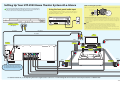
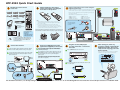
HTP-2920 Quick Start Guide
1
Check that you have all the
accessories.
Put the batteries in the remote
control and stick the non-skid pads
to the base of the speakers.
2
Connect each speaker to the receiver using the
supplied speaker wires.
3
INPUT SELECTOR
Front left (White)
Center (Green)
DVD
TV
DVR
RECEIVER
CD-R
FM
AM
Surround left
To connect, insert the colored wire into the matching positive (colored)
terminal and the other wire into the negative (black) terminal as shown
below. Connect the speakers the same way (matching the wire to the
color-coded terminal).
RECEIVER SLEEP DIMMER ANALOG ATT
Front right (Red)
Surround right
F.AUDIO
CD
Note that the color-coded terminals are as follows:
MIDNIGHT/
STANDARD ADV.SURR STEREO LOUDNESS
TOP MENU
Subwoofer (Purple) Surround right (Grey) Surround left (Blue)
SETUP
DIALOG E
ENTER
ONE
TOUCH
COPY
TUNER EDIT
Speaker cable x6
• Red : Front right (R)
• White : Front left (L)
• Green : Center speaker
MENU
• Purple : Subwoofer
• Grey : Surround right (R)
• Blue : Surround left (L)
RETURN
S.RETRIEVER
VOLUME
EFFECT/CH SEL
LEVEL
DVD/DVR
HDD
CH
GUIDE
FM wire antenna
AM loop
antenna
Batteries x2
(to confirm system
operation)
DVD
SUBTITLE
CH
AUDIO
REC
REC STOP
TIMER REC
INFO
DISPLAY
CLASS
DVD/DVR
SHIFT
MPX
TUNING STATION
JUKEBOX
TUNER
RECEIVER
1
2
FM UNBAL
75 Ω
AM
LOOP ANTENNA
Front left
CD
S
P
E
A
K
E
R
S
DIGITAL IN
COAX
IN
TV /
SAT
IN
CD-R
/ TAPE
/ MD
DVR
COAX
DVD/LD
OUT
Front and surround speakers
Connect the FM wire antenna and fully extend along a window
frame or another suitable place that receives good reception.
6
1
Use a red/white stereo audio cord (not supplied) to connect the
AUDIO TV IN jack on the receiver to the audio output on your
TV.* This will allow you to listen to your TV through this
speaker system.
2
R
AUDIO
L
FRONT
R
LR
SURROUND
CENTER
L
SUB WOOFER
Front right
Center
Receiver
Use a coaxial digital cord (not supplied) to connect the digital
output of your DVD player/recorder to the DIGITAL INPUT
(COAXIAL) DVD/DVR jack.
1
To connect the AM loop antenna, twist the exposed wire strands
together and insert into the terminal, then snap the connector
shut as shown below.
Subwoofer
Connect your DVD player/recorder
(optional-not supplied) to the receiver.
5
Connect the antennas.
Listening position
OPT
* The brackets are used in the Extra Power mode.
For details regarding how to set the Extra Power
mode, see the speaker system S-FCRW3100-K
Screws x4
Operating Instructions.
4
color-coded
wire
Subwoofer
You should also have:
• Speakers x5
• Subwoofer
• Operating instructions
• Mini plug audio cable
Brackets* x2
2
Twist and pull off the
protective shields on
each wire.
Stick the self-adhesive non-skid pads to the underside of each speaker, and
to the underside of the subwoofer. Use four pads per speaker (see below).
Remote control
Non-skid pads
(1x16, 1x4)
1
Note
• When disposing of used batteries, please comply with
governmental and/or environmental regulations that apply in
your country or area.
• Do not use or store batteries in direct sunlight or other
excessively hot places, such as inside a car or near a heater.
This can cause batteries to leak, overheat, explode or catch fire.
It can also reduce the life or performance of batteries.
MUTE
Plug the receiver, DVD player/
recorder and TV into a convenient
AC outlet.
Press STANDBY/ON to turn on the receiver.
AUDIO MULTI-CHANNEL RECEIVER
SX-218
MULTI JOG
STANDARD
* Note that you must also connect the DVD player/recorder’s
video output to your TV’s video input to watch a DVD video
(video cable is not supplied).
ADVANCED ST/DIRECT/
SURR
AUTO SURR
DVD/LD
TV/SAT
CD
DVR
DIMMER
ANALOG
ATT
MIDNIGHT/
LOUDNESS
SLEEP
CD-R / TAPE / MD
FRONT AUDIO
FM
AM
TUNING
STATION
MPX
VSB
MODE
DIALOGUE
ENHANCEMENT
MUTE
TUNER
EDIT
TONE
QUICK
SETUP
PHONES
DVD/DVR
MASTER
VOLUME
SETUP
RETURN
DOWN
UP
S
P
E
A
K
E
R
S
DIGITAL IN
IN
TV /
SAT
IN
CD-R
/ TAPE
/ MD
DVR
COAX
DVD/LD
OUT
OPT
R
AUDIO
GUIDE
AUDIO
REC
STANDBY/ON
2
CD
COAX
SUBTITLE
TIMER REC
INFO
REC STOP
JUKEBOX
AM
LOOP ANTENNA
OPT
AM
LOOP ANTENNA
DVD
CH
MULTI JOG
FM wire antenna
FM UNBAL
75 Ω
HDD
CH
FRONT
AUDIO INPUT
Receiver
Receiver
Refer to the receiver’s operating instructions for a detailed
explanation of this system’s surround sound features.
STANDBY/ON
Receiver
FM UNBAL
75 Ω
After turning on, make any
necessary settings required by the
DVD player/recorder, then you’re
ready to start enjoying your home
theater system.
ENTER
LISTENING MODE
AM loop
antenna
7
L
R
FRONT
LR
SURROUND
L
CENTER
SUB WOOFER
Turn on your DVD player/recorder and TV, and set the TV to the
correct video input.
VIDEO 1
CD
DIGITAL IN
COAX
TV /
SAT
IN
DVR
COAX
CD-R
/ TAPE
/ MD
IN
DVD/LD
OUT
R
AUDIO
L
S
P
E
A
K
E
R
S
R
STANDBY/ON
FRONT
VIDEO SELECT
TV
L
R
VIDEO
IN
AUDIO
OUT
TV
STANDBY/ON
10 mm
(3/8 in.)
DVD player/ recorder
(Not supplied)
DIGITAL
OUT
VIDEO
OUT
DVD player/ recorder
(Not supplied)
For detailed instructions, see the Operating Instructions supplied and/or contact one of our knowledgeable Pioneer Customer Service Representatives at 1-800-421-1404.
Setting Up Your HTP-2920 Home Theater System At-a-Glance
Refer to the following diagram when making system connections for a full surround sound
setup. Note that the TV, DVD player/recorder and some accessories are not included. Refer to
the reverse side of this sheet to check what’s supplied with the HTP-2920.
Wall mounting the speakers
The front, center and surrond speakers has a mounting hole which can be used to mount the speaker on the
wall.
Using the front panel audio input
Mounting screw
(not supplied)
Use the supplied mini-plug cable to connect an audio device
(portable audio player, etc.) to the front panel audio input for
playback through this system.
5 mm
(3/16 in.)
10 mm
(3/8 in.)
5 mm to 7 mm
(3/16 in. to 1/4 in.)
AUDIO MULTI-CHANNEL RECEIVER
Before mounting (see above), keep in mind the following points:
SX-218
MULTI JOG
• Remember that the speaker system is heavy and that its weight could cause the screws to work loose, or
the wall material to fail to support it, resulting in the speaker falling. Make sure that the wall you intend to
mount the speakers on is strong enough to support them. Do not mount on plywood or soft surface walls.
• Mounting screws are not supplied. Use screws that are suitable for the wall material and can support the
weight of the speaker.
ENTER
STANDARD
ADVANCED ST/DIRECT/
SURR
AUTO SURR
DVD/LD
TV/SAT
CD
DVR
CD-R / TAPE / MD
FRONT AUDIO
AM
FM
TUNING
STATION
MPX
VSB
MODE
DIALOGUE
ENHANCEMENT
LISTENING MODE
DIMMER
ANALOG
ATT
MIDNIGHT/
LOUDNESS
SLEEP
MUTE
TUNER
EDIT
TONE
QUICK
SETUP
MASTER
VOLUME
STANDBY/ON
PHONES
menu
SETUP
RETURN
FRONT
AUDIO INPUT
MULTI JOG
DOWN
DVD player/ recorder
COAXIAL OUT
Caution
UP
• If you are unsure of the qualities and strength of the walls, consult a professional for advice.
• Pioneer is not responsible for any accidents or damage that result from improper installation.
• Do not hang the subwoofer on the wall or from the ceiling as they might fall and cause injury.
• When placing this unit, ensure that it is firmly secured and avoid areas where it may be likely to fall and
cause injuly in the event of a natural disaster (such as an earthquake).
For more information about speaker installation, please see the instructions that come with the speakers.
VIDEO OUT
(Not supplied)
Mini plug audio cable
Not supplied
Not supplied
Not supplied
TV
AUDIO
OUT
(White)
VIDEO
IN
(Red)
Receiver
Subwoofer
FM UNBAL
75 Ω
–
–
Front L.
AM
LOOP ANTENNA
+
+
Front R.
Center
OPT
–
CD
DIGITAL IN
COAX
IN
TV /
SAT
IN
CD-R
/ TAPE
/ MD
DVR
COAX
DVD/LD
OUT
R
AUDIO
L
S
P
E
A
K
E
R
S
R
FRONT
LR
SURROUND
L
CENTER
+
(Green)
SUB WOOFER
–
+
(Purple)
(Grey)
(Blue)
Surround L.
Surround R.
–
The illustration above shows the connection
for a DVD player (the DVD/LD jack). Connect to
the DVR jack when connecting a DVD recorder.
–
+
+
For detailed instructions, see the Operating Instructions supplied and/or contact one of our knowledgeable Pioneer Customer Service Representatives at 1-800-421-1404.
<XRE3204-A>