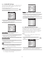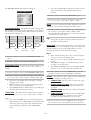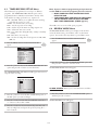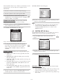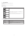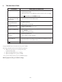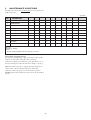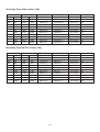
1
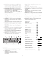
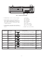
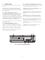
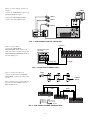
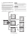
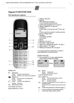
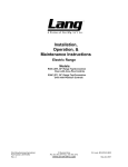
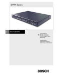
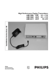
PHILIPS RT30A & RT960A
High Density Video Cassette Recorder
en
fr
de
Instructions for Use
es
Philips
Communication,
Security & Imaging
nl
it
pt
IMPORTANT SAFEGUARDS
VENTILATION
17. Keep ventilation openings free to avoid the recorder for overheating.
18. Do not place the recorder in the immediate vicinity of a heating source.
19. Do not install this equipment in a confined space such as a bookcase or
similar unit.
CLEANING
CAUTION
CAUTION:TO REDUCE THE RISK OF ELECTRIC
SHOCK, DO NOT OPEN COVERS. NO USER
SERVICEABLE PARTS INSIDE. REFER SERVICING
TO QUALIFIED SERVICE PERSONNEL.
20. You can clean the recorder with a moist fluff-free cloth or shammy leather
cloth.
DISPOSAL
21. This recorder contains a battery.
Do not dispose of the battery
with other solid waste. The
battery is located inside the
recorder. To remove the battery,
remove the recorder cover by
unscrewing the 4 crosshead
screws, remove the cover, then
break off the battery from the
circuit board.
The lightning flash with an arrowhead symbol, within an equilateral
triangle, is intended to alert the user to the presence of uninsulated
“dangerous voltage” within the product’s enclosure that may be of
sufficient magnitude to constitute a risk of electric shock to
persons.
The exclamation point within an equilateral triangle is intended to
alert the user to presence of important operating and maintenance
(servicing) instructions in the literature accompanying the
appliance.
1.
2.
3.
4.
5.
6.
7.
8.
9.
10.
11.
12.
13.
14.
Read these instructions.
Keep these instructions.
Comply with all warnings.
Follow all instructions.
Do not use this equipment near water.
Clean only with dry cloth.
Do not block any ventilation openings. Install in accordance with the
manufacturer’s instructions.
Do not install near any heat sources such as radiators, heat registers, stoves, or
other equipment (including amplifiers) that produce heat.
Do not defeat the safety purpose of the polarized or grounding-type plug. A
polarized plug has two blades with one wider than the other. A grounding
type plug has two blades and a third grounding prong. Both the wide blade
and the third prong are provided for your safety. If the provided plug does not
fit into your outlet, consult an electrician for replacement of the obsolete
outlet.
Protect the power cord from being walked on or pinched particularly at plugs,
convenience receptacles, and the point where they exit from the equipment.
Only use attachments/accessories specified by the manufacturer.
Unplug this equipment during lightning storms or when unused for long
periods of time.
Refer all servicing to qualified service personnel. Servicing is required when
the equipment has been damaged in any way, such as power-supply cord or
plug is damaged, liquid has been spilled or objects have fallen into the
equipment, the equipment has been exposed to rain or moisture, does not
operate normally, or has been dropped.
WARNING:To reduce the risk of fire or electric shock, do not expose this
equipment to rain or moisture.
BATTERY
Front of Recorder
CAUTION: Danger of explosion if batteries are incorrectly replaced.
Replace only with the same or equivalent type.
Remark: Philips has a strong commitment towards the environment.This recorder has
been designed to respect the environment as much as possible.
FCC Information
This equipment has been tested and found to comply with the limits for a Class B
digital device, pursuant to part 15 of the FCC Rules. These limits are designed to
provide reasonable protection against harmful interference in a residential
installation. This equipment generates, uses and can radiate radio frequency energy
and, if not installed and used in accordance with the instructions, may cause
harmful interference to radio communications. However, there is no guarantee
that interference will not occur in a particular installation. If this equipment does
cause harmful interference to radio or television reception, which can be
determined by turning the equipment off and on, the user is encouraged to try to
correct the interference by one or more of the following measures:
Reorient or relocate the receiving antenna.
Increase the separation between the equipment and receiver.
Connect the equipment into an outlet on a circuit different from that to
which the receiver is connected.
Consult the dealer or an experienced radio/ TV technician for help.
Note: Any change or modification not expressly approved by Philips of the
equipment authorization could void the user's authority to operate the equipment.
For additional information or to speak to a representative, please contact the
Philips Communication, Security & Imaging location nearest you or visit our web
site at www.Philipscsi.com.
(See: Your Guide To Observation)
15. The equipment shall not be exposed to dripping or splashing and that no
objects filled with liquids, such as vases, shall be placed on the equipment.
16. The back of the recorder should only be removed by qualified maintenance
and service personnel.
WARNING:This device is intended for use in public areas only.
Surreptitious recording of oral communications is strictly prohibited
by U.S. Federal law
1-1
CONTENTS
1
UNPACKING . . . . . . . . . . . . . . . . . . . . . . . . . . . . . . . . . . . . . . . . . . . . . . . . . . . . . . . . . . . . . . . . . . . . . . .1-3
2
SERVICE . . . . . . . . . . . . . . . . . . . . . . . . . . . . . . . . . . . . . . . . . . . . . . . . . . . . . . . . . . . . . . . . . . . . . . . . . . .1-3
3
DESCRIPTION . . . . . . . . . . . . . . . . . . . . . . . . . . . . . . . . . . . . . . . . . . . . . . . . . . . . . . . . . . . . . . . . . . . . . .1-3
4
4.1
CONTROLS . . . . . . . . . . . . . . . . . . . . . . . . . . . . . . . . . . . . . . . . . . . . . . . . . . . . . . . . . . . . . . . . . . . . . . .1-4
Controls and Functions . . . . . . . . . . . . . . . . . . . . . . . . . . . . . . . . . . . . . . . . . . . . . . . . . . . . . . . . . . . . . . .1-4
5
5.1
5.2
5.3
5.4
5.5
5.6
5.7
INSTALLATION . . . . . . . . . . . . . . . . . . . . . . . . . . . . . . . . . . . . . . . . . . . . . . . . . . . . . . . . . . . . . . . . . . . . .1-7
Video Connection (Fig 4, Item 3) . . . . . . . . . . . . . . . . . . . . . . . . . . . . . . . . . . . . . . . . . . . . . . . . . . . . . . . .1-7
Audio Connection (Fig 4, Item 2) . . . . . . . . . . . . . . . . . . . . . . . . . . . . . . . . . . . . . . . . . . . . . . . . . . . . . . . .1-7
Using the 12-pin Terminals (Fig 4, Item 4) . . . . . . . . . . . . . . . . . . . . . . . . . . . . . . . . . . . . . . . . . . . . . . . . . .1-7
VCR Setup . . . . . . . . . . . . . . . . . . . . . . . . . . . . . . . . . . . . . . . . . . . . . . . . . . . . . . . . . . . . . . . . . . . . . . . . .1-8
Video Cassette Tapes . . . . . . . . . . . . . . . . . . . . . . . . . . . . . . . . . . . . . . . . . . . . . . . . . . . . . . . . . . . . . . . .1-10
Normal Playback . . . . . . . . . . . . . . . . . . . . . . . . . . . . . . . . . . . . . . . . . . . . . . . . . . . . . . . . . . . . . . . . . . .1-10
Normal Recording . . . . . . . . . . . . . . . . . . . . . . . . . . . . . . . . . . . . . . . . . . . . . . . . . . . . . . . . . . . . . . . . . .1-12
6
6.1
6.2
6.3
6.4
6.5
6.6
Setting the On-Screen Display .
CLOCK SET UP Menu . . . . . . .
RECORD MODE SET UP Menu
TIMER RECORD SET UP Menu
REVIEW MODE Menu . . . . . . .
SYSTEM SET UP Menu . . . . . . .
SEARCH SET UP Menu . . . . . . .
7.
SELF-DIAGNOSIS
8.
9.
10.
TROUBLESHOOTING . . . . . . . . . . . . . . . . . . . . . . . . . . . . . . . . . . . . . . . . . . . . . . . . . . . . . . . . . . . . . . .1-20
MAINTENANCE GUIDE TABLE . . . . . . . . . . . . . . . . . . . . . . . . . . . . . . . . . . . . . . . . . . . . . . . . . . . . . . .1-21
SPECIFICATIONS . . . . . . . . . . . . . . . . . . . . . . . . . . . . . . . . . . . . . . . . . . . . . . . . . . . . . . . . . . . . . . . . . .1-22
.
.
.
.
.
.
.
.
.
.
.
.
.
.
.
.
.
.
.
.
.
.
.
.
.
.
.
.
.
.
.
.
.
.
.
.
.
.
.
.
.
.
.
.
.
.
.
.
.
.
.
.
.
.
.
.
.
.
.
.
.
.
.
.
.
.
.
.
.
.
.
.
.
.
.
.
.
.
.
.
.
.
.
.
.
.
.
.
.
.
.
.
.
.
.
.
.
.
.
.
.
.
.
.
.
.
.
.
.
.
.
.
.
.
.
.
.
.
.
.
.
.
.
.
.
.
.
.
.
.
.
.
.
.
.
.
.
.
.
.
.
.
.
.
.
.
.
.
.
.
.
.
.
.
.
.
.
.
.
.
.
.
.
.
.
.
.
.
.
.
.
.
.
.
.
.
.
.
.
.
.
.
.
.
.
.
.
.
.
.
.
.
.
.
.
.
.
.
.
.
.
.
.
.
.
.
.
.
.
.
.
.
.
.
.
.
.
.
.
.
.
.
.
.
.
.
.
.
.
.
.
.
.
.
.
.
.
.
.
.
.
.
.
.
.
.
.
.
.
.
.
.
.
.
.
.
.
.
.
.
.
.
.
.
.
.
.
.
.
.
.
.
.
.
.
.
.
.
.
.
.
.
.
.
.
.
.
.
.
.
.
.
.
.
.
.
.
.
.
.
.
.
.
.
.
.
.
.
.
.
.
.
.
.
.
.
.
.
.
.
.
.
.
.
.
.
.
.
.
.
.
.
.
.
.
.
.
.
.
.
.
.
.
.
.
.
.
.
.
.
.
.
.
.
.
.
.
.
.
.
.
.
.
.
.
.
.
.
.
.
.
.
.
.
.
.
.
.
.
.
.
.
.
.
.
.1-13
.1-14
.1-14
.1-16
.1-16
.1-17
.1-18
. . . . . . . . . . . . . . . . . . . . . . . . . . . . . . . . . . . . . . . . . . . . . . . . . . . . . . . . . . . . . . . . . .1-19
1-2
1
UNPACKING
Alarm detection is operational from the recording or ready modes
and will turn on the alarm indicator and "Alarm-On" output. It
also inserts an Alarm-Code in the on-screen display for easy
location during later alarm search. The selected alarm recording
speed can be programmed to continue for a period of 30 seconds,
1, 3, 5, 10 minutes or until tape end.
Unpack carefully. This is electronic equipment and should be
handled carefully. Check to ensure that the following items are
included:
Model number of VCR.
This Instruction for Use.
If an item appears to have been damaged in shipment, replace it
properly in its carton and notify the shipping agent. If any items
are missing, notify your Philips Communication, Security &
Imaging Sales Representative or Customer Service. The shipping
carton is the safest container in which the unit may be
transported. Save it for possible future use.
Whatever your needs are for recording and monitoring, the
RT30A and RT960A will provide you with a trouble free, easy-touse advanced real-time video recording for your specific
application area.
2
Recording:
Double (PAL)/Triple (NTSC) Density Video Cassette
Recorder.
RT30A has three Selectable Recording Speeds (6, 18, 30
hours). RT960A has ten Selectable Recording Speeds (6,
18, 30, 72, 96, 120, 168, 240, 480, 960 hours).
High speed rewind (less than 70 sec. [E180/T120 tape]).
Alarm recording with selectable duration and selectable
recording speed.
Recording Check.
On-Screen and On-Tape Time/Date Information.
8 programmable 7-day program timer settings.
Tape remain Information.
Automatic repeat recording.
Automatic recording restart after power loss has been
restored.
Series recording (when using two or more VCRs).
“Alarm On” Output.
Audio at 6, 18 and 30 hour speeds.
Features include:
SERVICE
If the unit ever needs repair service, the customer should contact
their Dealer or Service Center for return authorization and
shipping instructions.
3
DESCRIPTION
When you use a VCR as backup to your observation and
monitoring practices, you no longer have to worry about missing
a thing. With the RT30A and RT960A Series 30hr and 960hr
High Density Video Cassette Recorders you have superior video
and audio quality with the versatility to best suit your application
needs.
The high density RT30A and RT960A feature gives you double
(PAL) / triple (NTSC) the number of picture updates per second
than conventional VCRs, ensuring you do not miss any incident,
yet keeping the high quality picture. Highly developed compact
mechanical components ensure long lasting reliability even with
the high speed rewind of less than 70 sec.
Playback:
Time-of-Alarm Memory and Alarm Index Search.
High Speed Visual Search.
RT30A has three Playback Speeds (6, 18, 30 hours),
RT960A has ten Playback Speeds (6, 18, 30, 72, 96, 120,
168, 240, 480, 960 hours).
Still Field, Field-Advance, and Field-Reverse.
The RT30A gives the option of recording events with 6, 18 or 30
hrs of real-time video. The RT960A provides the same real-time
video plus up to 960 hrs of time-lapse video. Audio recording
and playback is also available in the 6, 18 and 30 hour modes.
Fantastic features like the superimosed on-screen menu in 7
languages provide easy setup. Other features include built-in
time/date generator, a built-in back-up battery that provides
time/date/settings backup during power loss for up to 2 weeks,
joggle shuttle for instant picture retrieval, tape remaining
indication and automatic recording after power failure. The list is
endless, ensuring that these VCRs can meet your required
application specification.
Security:
Built-in rechargeable back-up battery (2 weeks).
Electronic Security Lockout.
Technically the RT30A and RT960A are the most advanced RealTime video recorders available. V-Sync selection, "videothrough", security-lock, video-loss, Vext-pulse and V-Lock
functions are just a few features that will enhance the functions
that need special attention.
1-3
4
CONTROLS
Repacking:
It is wise to save the packing materials and box in case you
ever need to ship or store your unit.
Note: This recorder has a battery to maintain display functions
and recording mode within 2 weeks in the event of power loss.
When the recorder is received, the unit must be connected to
power source for 48 hours to assure the battery has been
adequately charged.
4.1 Controls and Functions
Operational Controls:
1. POWER button - Press for on; press again for off.
The display window becomes brighter when the VCR is
switched on.
When you select power off, the timer program is
operational if the option has been setup.
2. REC (RECORD) button - Press to begin recording.
3. Cassette loading slot - Cassette tape is inserted in this slot.
4. Shuttle Ring - The shuttle ring is the outer dial. When the
VCR is in STOP mode, the shuttle ring can be rotated to
the left or right then released, and the VCR will engage in
the REWIND or FAST FORWARD function. While in
the REWIND or FAST FORWARD mode, the shuttle
ring can be rotated and held to engage the LOGIC search
mode. Releasing the shuttle ring returns it to the
REWIND or FAST FORWARD function. Refer to
paragraph 5.6.1 for detailed operation.
5. Jog Ring - The jog ring is the center dial of the jog-shuttle
ring. This ring is used to advance or reverse the video by
single field when in the still mode. Refer to paragraph
5.6.1 for detailed operation.
6. PLAY button - Press to play back a previously recorded
tape. Pressing this button while recording provides
confirmation of the recording operation. The tape plays
back the last 4 seconds of video then returns to the
recording mode.
7. STOP button - Press once to discontinue all tape related
functions. Press a second time to eject the cassette.
8. STILL button - When pressed during recording, tape
movement stops temporarily. Press again to continue the
recording. When pressed during playback, tape movement
stops. Press again to advance by still frame. Press the PLAY
button to continue playback.
9. CLEAR button - Press to delete the information stored on
the screen display, such as Alarm review, Power fail and
Timer program. It can also be used to stop the buzzer
sound.
Safety
Should any solid object or liquid fall into the cabinet,
turn off the unit and have it checked by qualified
personnel before operating it any further.
To disconnect the power cord, pull it out by the plug.
Never pull the cord itself.
Installation Requirements:
Choose a location in which air can pass through the
ventilation holes in the bottom, top and back of the unit
to prevent it from overheating.
Do not install the unit near sources such as radiators or air
ducts or in a place subject to direct sunlight, excessive
dust, mechanical vibrations or shock.
Never bring a magnet or magnetized object near the VCR
because it will adversely affect the performance of the
VCR.
Do not install the unit in an inclined position. The unit is
designed for operation in a horizontal position.
Operation:
Condensation: If you pour a cold liquid into a glass, water
vapor in the air will condense on the surface of glass. This
is the condensation of moisture. Condensation on the
head drum, one of the most crucial parts of the VCR, will
cause damage to the tape. The VCR should not be
operated for at least 2 hours after being moved from a cold
to a hot environment to avoid condensation from
occurring on the head drum.
Cleaning:
Be careful: When surface of the case is wiped with a
volatile agent such as benzine, alcohol, thinner, etc., or a
chemically processed cloth, the surface finish may be
degraded or its coating may peel off.
PHILIPS
High Density Video Cassette Recorder
D
FIG. 1 - RT30A & RT960A FRONT
1-4
10. DISPLAY button - Pressing this button toggles between
the CLOCK, COUNT and REMAIN displays. CLOCK
shows the current time, COUNT shows the incremental
counter for recording or playing, and REMAIN indicates
the remaining time on the tape.
11. REC/PB SPEED UP- Selects the record/playback tape
speed. UP button - Press to select from an ascending order,
the record/ playback speed (6H, 18H, 30H...).
Menu operation: + button - Press to change the value of a
setting on the menu screen.
12. REC/PB SPEED DOWN- Selects the record/playback
tape speed. DOWN button - Press to select from a
descending order, the record/playback speed (960H,
480H...).
Menu operation: - button - Press to change the value of a
setting on the menu screen.
13. TRACKING (↓ )- If noise appears on the screen during
playback, press to adjust the tracking during the playback
or slow mode.
Menu operation: ↓ button - Press to move the cursor down
to the next available option on the menu screen.
14. TRACKING (→)- If noise appears on the screen during
playback, press to adjust the tracking during the playback
or slow mode.
Menu operation: → button - Press to move to the next
menu screen.
15. V-LOCK button - If a picture is vertically vibrating during
still mode or playback, press V-LOCK buttons until the
vertical jitter on the Screen is reduced
16. KEY LOCK button - The KEY LOCK setting allows the
user to prevent changes to the setting. The VCR stays in
the current mode. Press again to unlock.
17. MENU button - Press to display and change the settings
of the VCR while viewing on the video monitor.
3. SERIES indicator - Lights when you use two or more
VCRs in series.
4. REC indicator - Lights when recording.
5. TIMER indicator - Lights when the timer recording mode
is operating.
6. CASSETTE indicator - Lights when a cassette is loaded in
the VCR.
7. INDEX indicator - Lights when scanning for playback
detection of alarm events.
8. P.FAIL indicator - Lights when the VCR power had failed.
9. K.LOCK indicator - Lights when the key lock function is
operational.
10. REPEAT indicator - Lights when repeat recording option
is selected.
11. FUNCTION indicator - Displays the time, counter,
remain indication.
12. VCR indicator - Displays the current VCR operational
function as listed in the table below:
VCR Indication
PLAYBACK . . . . . . . . . . . . . . . . .
REVERSE PLAYBACK . . . . . . . . .
STILL . . . . . . . . . . . . . . . . . . . . . .
FAST FORWARD . . . . . . . . . . . .
REWIND . . . . . . . . . . . . . . . . . . .
FORWARD SLOW/
FIELD ADVANCE . . . . . . . . . . . .
REVERSE SLOW/
FIELD ADVANCE . . . . . . . . . . . .
CUE . . . . . . . . . . . . . . . . . . . . . . .
REVIEW . . . . . . . . . . . . . . . . . . .
RECORDING . . . . . . . . . . . . . . .
TIMER RECORDING . . . . . . . . .
ALARM INDEX SEARCH . . . . . .
ALARM RECORDING . . . . . . . .
FIG. 2 DISPLAY WINDOW
SERIES RECORDING . . . . . . . . .
DOUBLE-SPEED PLAY . . . . . . . .
Display Window:
1. VCR Speed indicator - Displays the selected VCR speed,
A6, A18, A30, 72, 96 etc….(A = Audio)
2. ALARM indicator
ALARM appears during alarm recording.
ALARM flashes when alarm recording ends or
acknowledged.
REVERSE TRIPLE-SPEED PLAY .
1-5
AUDIO
FIG. 3 - RT30A & RT960A REAR
Rear Connection Panel
1. POWER CORD - Connect to correct power supply.
4. 12-PIN TERMINAL - Provides inputs/outputs for
operational use:
Pin 1 – Alarm IN
Pin 3- Alarm OUT
Pin 5 – Series IN
Pin 6 – Series OUT
Pin 8 – VEXT
Pin 10 – Tape end OUT
Pin 11 – 1-Shot record IN
Pins 2, 4, 7, 9, 12 - GND
2. AUDIO IN/OUT - Accepts an audio signal from a
camera, external sound equipment or another recorder
(Line: –6 dBm, 47 kOhm, unbalanced). Provides an
audio output for a monitor or another VCR (–9 dBm,
1.5 kOhm, unbalanced).
3. VIDEO IN/OUT - IN - Receives video signal from a
video camera or another VCR. OUT - For connection to
monitor.
TERMINAL
FUNCTION
1.
ALARM IN
VIH
5. RESET - Press to reset the VCR.
SIGNAL LEVEL
IN/OUT
VIL
VIH: 4-5V VIL: 0--.6V, T : above 500 msec.
INPUT
VOL
VOH: 4-5V VOL: 0--.6V, T : Alarm rec. state
OUTPUT
VIL
VIH: 4-5V VIL: 0--.6V, T : above 500 msec.
INPUT
VOL
VOH: 4-5V VOL: 0--.6V, T : above 500 msec.
OUTPUT
VOL
VOH: 4-5V VOL: 0--.6V, T : above 500 msec.
OUTPUT
VOL
VOH: 4-5V VOL: 0--.6V, T : above 500 msec.
end of tape or low tape or DECK error
OUTPUT
VIL
VIH: 4-5V VIL: 0--.6V, T : above 500 msec.
INPUT
OV
COMMON
T
3.
ALARM OUT
VOH
T
5.
SERIES IN
VIH
T
6.
SERIES OUT
VOH
T
8.
VEXT
VOH
T
10.
TAPE END OUT
VOH
T
11.
1-SHOT REC IN
VIH
T
2, 4, 7, 9, 12.
GND
1-6
5
INSTALLATION
5.3 Using the 12-pin Terminals (Fig 4, Item 4)
Use coaxial cables when connecting a camera and a monitor to
this VCR.
Attach the wires of the alarm switch, door sensor or warning lamp
to the 12-pin terminal by pushing in the cable wire.
Note: Long cable runs to distant cameras may cause signal
deterioration and/or sync discrepancies. If these problems occur,
use video line amplifiers and/or cameras having phase-adjustable
line-locked vertical sync.
ALARM IN - You can connect an alarm input from a
switcher/multiplexer to record an alarm event on tape. Connect
input to pin 1 and ground to pin 9.
ALARM OUT - Approx. 5V is applied to pin 3 during an alarm
recording. This can be used to trigger an external device (i.e.
alarm bell).
5.1 Video Connection (Fig 4, Item 3)
Video Input - In single camera systems, connect the camera to the
Video IN BNC terminal on the VCR rear panel. In multiple
camera systems, connect the switcher/multiplexer output to the
Video IN BNC terminal. Because multiple camera systems require
synchronization, use of cameras having line-locked vertical sync or
a genlocked master drive/sync source is highly recommended. The
use of vertical interval switchers is also recommended.
SERIES - When two or more of this VCR model are used,
connect via these terminals. See Series Record Connection for
details. Connect Series IN to pin 5 and Series OUT to pin 6.
VEXT - Pin 8 outputs the following signal each time a one-field
image is recorded. You can combine this with a video camera
multiplexer which can be controlled externally.
Video Output - Connect the monitor to the Video OUT BNC
terminal on the rear panel.
TAPE END OUT - Approx. 5V is applied to pin 10 when the
tape reaches the end.
5.2 Audio Connection (Fig 4, Item 2)
Audio can be recorded at 6H, 18H, 30H speeds. To hear the
playback sound, use the 6H, 18H or 30H speed during playback.
1-SHOT REC IN - You can connect this input (pin 11) to
ground (pin 12) to start a 1-shot recording.
Audio In: Accepts an audio signal from a camera, external sound
equipment, or another recorder (Line: –6 dBm, 47 kOhm).
Audio Out: Provides an audio output for a monitor or another
recorder (–9 dBm, 1.5 kOhm, unbalanced).
AUDIO
FIG. 4 - RT30A & RT960A CONNECTION
1-7
5.4 VCR Setup
Note: The cable of audio and video are
not provided with your VCR.
MONITOR
How to connect a single camera:
Connect the VCR AUDIO/ VIDEO
outputs to the MONITOR AUDIO/
VIDEO inputs.
Connect the CAMERA AUDIO/
VIDEO output to the VCR AUDIO/
VIDEO input.
To AUDIO IN
To VIDEO IN
To AUDIO OUT
AUDIO
VCR's Back Panel
To VIDEO OUT
To AUDIO IN
To VIDEO IN
CAMERA
FIG. 5 - VCR CONNECTION TO SINGLE CAMERA (AUDIO & VIDEO)
MONITOR
CAMERA 1
How to connect a Multiplexer with
VEXT Input Terminals:
Connect the VCR VIDEO output to
the MULTIPLEXER PLAYBACK input.
CAMERA 2
.
.
CAMERA 8
Connect the VCR VIDEO input to the
MULTIPLEXER REC output.
Connect the VCR VEXT pin 8 to the
MULTIPLEXER VEXT terminal.
VEXT
VCR
Connect the MULTIPLEXER GND
terminals to the VCR GND pin 9.
To TRIGGER IN
From GROUND
MULTIPLEXER
To GROUND
FIG. 6 - VCR CONNECTION TO MULTIPLEXER WITH TRIGGER FUNCTION
1-8
How to connect multiple cameras via
switcher:
Connect the VCR VIDEO output to the
MONITOR VIDEO input.
MONITOR
CAMERA 1
Connect the SWITCHER VIDEO
output to the VCR VIDEO input.
CAMERA 2
.
.
CAMERA 8
VCR
SWITCHER
FIG. 7 - VCR CONNECTION TO SWITCHER
How to connect Alarms:
Connect the SWITCHER/
MULTIPLEXER alarm output to the
VCR alarm input, and then connect the
SWITCHER/MULTIPLEXER GND to
the VCR GND pin 4.
To ALARM IN
SWITCHER/MULTIPLEXER
BACK PANEL
VCR BACK PANEL
To ALARM OUT
To GROUND
To GROUND
FIG. 8 - VCR ALARM CONNECTION
How to connect Series Record:
Connect the first VCR to CAMERA/
SWITCHER. Connect the other VCRs
in series.
CAMERA
To MONITOR's
VIDEO IN
After connecting, turn on the VCR, and
then select the ON: SERIES mode in
REC MODE menu.
GROUND
GROUND
VCR 1
ALARM
ALARM
SERIES
SERIES
IN
OUT
IN
OUT
VEXT
TAPE END OUT
1-SHOT REC IN
GROUND
FIG. 9 - VCR SERIES RECORD CONNECTION
1-9
VCR 2
VCR 3
5.5 Video Cassette Tapes
5.6 Normal Playback
This VCR will operate with any video cassette which has the
VHS mark.
Turn on the power of both the VCR and the MONITOR.
1. Insert a prerecorded video cassette.
When handling video cassette tapes:
• Do not expose video cassettes to extreme heat, high humidity, or
strong magnetic fields.
• Do not tamper with the cassette mechanism.
• Do not touch the tape with your fingers.
• Always store an unused cassette in its case.
LOADING
UNLOADING
SAFETY TAB
The
indicator will light and the VCR will power-up
automatically.
If a tape without a record protect tab is inserted, the unit will start
the playback automatically
2. Press the PLAY button.
Loading:
Hold the cassette with the arrow side
up (top). Insert the cassette gently
into the slot in the direction of the
arrow (on the cassette) until the
loading mechanism automatically
pulls the cassette into the unit. Make
certain that the cassette is inserted
correctly.
• If the cassette is not loaded
correctly, the VCR will eject the
cassette automatically after
approximately 3 seconds.
PLAY
Press - or + button to choose the desired time mode,
6H, 18H, 30H etc.
The selecting time is displayed in the VCR indicator
panel.
If the tape reaches the end before STOP is pressed,
the VCR will automatically stop and rewind.
3. Press the STOP button to stop playback.
STOP/EJECT
Note:
Unloading:
Press the STOP/EJECT button twice.
The cassette will be ejected
automatically. After the cassette is
visible in the tape slot, pull it out to
remove it.
• Unloading the cassette is possible
only when the power cord is
connected to the wall outlet.
• The cassette can be ejected when
the STOP/EJECT button is pressed,
even if the VCR’s power is OFF.
Video cassette safety tab:
To prevent accidental erasure of
recorded material, remove the safety
tab from the lower left corner of the
cassette. Recording is impossible
when the safety tab is removed.
REC/PB SPEED
If during playback the STILL button is pressed, then after
5 minutes in this mode, the playback will automatically go
into standby mode to protect the tape and video heads.
Tracking Control:
If noise appears on the screen during playback,
press either ↓ or → buttons until the noise on the
screen is reduced. In case of vertical jitter, adjust
these controls very carefully. Tracking is
automatically reset to normal when the tape is
ejected.
V-Lock Control:
If a picture is vibrating vertically during still mode,
18, 30 or playback, press V-LOCK buttons until
the vertical jitter on the screen is reduced.
Notes:
A picture may have a slight vertical vibration, but this is
normal.
A distortion may appear on the top of the screen, but this
is normal.
If the recording speed and playback speed are different, the
sound may not be play back normally.
1-10
5.6.1 Special Effects Playback
How to use the Shuttle Ring:
The shuttle ring is the outer dial. When the VCR is in the STOP
mode, the shuttle ring can be rotated to the left or right then
released, and the VCR will engage in the REWIND or FAST
FORWARD function. While in the REWIND or FAST
FORWARD mode, the shuttle ring can be rotated and held to
engage the search mode. Releasing the shuttle ring returns it to
the REWIND or FAST FORWARD function.
During Playback Mode:
When a picture is in the playback
mode, the video can be viewed at
variable speeds by rotating and
holding the shuttle ring at different
positions.
5.6.2 Tape Counter Memory Feature
Real time Counter during PLAYBACK or
RECORDING mode:
Press the DISPLAY button.
DISPLAY
Whenever you press the DISPLAY
button, the time, counter or
remaining time is displayed
alternately in the VCR indicator
panel.
PLAY
REVERSE
PLAY
REVERSE
TRIPLE-SPEED
PLAY
DOUBLE-SPEED
PLAY
REVERSE
SEARCH
FORWARD
SEARCH
The figure illustrates the action
that will occur at various positions.
The VCR returns to the playback mode upon release of the
shuttle ring.
During Still Mode:
When a picture is in the still mode, the video can be
viewed at variable speeds, including slow motion, by
rotating and holding the shuttle ring at different
positions.
When the COUNTER is
displayed:
Counter changes to
CLOCK when the cassette
is ejected.
The real-time counter does
not operate when nothing
is recorded on the tape.
Counter Memory Function:
This function is only provided when the COUNTER option is
displayed in the VCR indicator panel.
1. Begin recording or playing a tape.
PLAY
Continue to play or record.
The figure illustrates the action that will occur at various
positions.
2. At the point where you want the playback to begin,
reset the real-time counter to 0:00:00 by pressing the
CLEAR button.
The VCR returns to the still mode upon release of the shuttle
ring.
3. Press the STOP button when recording or playback
finishes.
How to use the Jog Ring:
The jog ring is the center dial of the jog-shuttle ring.
This ring is used to advance or reverse the video by
single field when in the still mode.
4. Rotate and release the SHUTTLE ring to
reverse.
To scan for alarm recordings, refer to paragraph 6.6.
CLEAR
STOP/EJECT
The VCR will stop at the COUNTER
position 0:00:00.
Tape Remaining:
This function allows the time of the remaining tape to be
displayed during recording or playback.
1. Press the DISPLAY button until the remaining time
displays on the TV screen.
DISPLAY
2. Start recording or playback.
Note: The remaining time is not displayed during 72H, 96H,
.....000H recording or playback mode.
1-11
5.7 Normal Recording
Turn on the power of both the VCR and the MONITOR.
1. Insert the VIDEO CASSETTE. Ensure the safety tab is in
place.
2. Press – or + to choose the desired recording speed,
6H, 18H, 30H etc.
The selected time is displayed in the VCR indicator panel, A6H >
A18H > A30H > 72H > 96H > 120H > 160H > 240H > 480H >
960H > 000H.
Notes:
If you select the '000H' option in normal recording, the
VCR will activate the '1SHOT REC' mode function. This
will record a single shot picture after each defined time
interval which is programmed in the '1SHOT REC' menu
(see 6.2 Record Mode Set Up menu). You can select the
'1SHOT REC' time interval for 1 sec., 3 sec., 5 sec., 15
sec., 30 sec., 60 sec., or OFF.
If you select '1SHOT REC' OFF, the unit will record one
picture each time the external 1SHOT REC input is
activated.
3. Press the REC button.
Recording will start. (The REC indicator will light in
VCR indicator panel.)
4. Press the STOP button to stop recording.
To PAUSE the recording during the RECORDING mode:
1. Press the STILL button to pause the tape.
2. When you want to continue recording, press the
STILL button again.
After 5 minutes in STILL mode, the recording will automatically
go into the standby mode to protect the tape and the video heads.
To Record Check during the RECORDING mode:
When in record mode, pressing the PLAY should cause the unit
to reproduce recently recorded video.
3. Press PLAY to reproduce recently recorded video.
(Playback of the last 4 seconds of recorded video will
be displayed).
After the Record Check, the unit return to the original recording
mode.
1-12
6
SETTING THE ON-SCREEN DISPLAY
LANGUAGE:
This allows you to view the menus in your selected language.
The MAIN MENU displays a list of options that you can use to
setup the VCR.
1. Press the ↓ button to select the LANGUAGE option and then
press the → button to toggle between English, French,
Spanish, German, Italian, Dutch and Portuguese.
1. Turn on the power of both the VCR and the MONITOR.
2. Press MENU button and the main menu will
appear.
MENU
OTHER MENUS:
You can setup the VCR to your specific requirements using the
menus listed. The functionality of each menu is described in the
following paragraphs.
3. Select the desired menu with the ↓ button and then press the
→ button to enter the respective menu table.
4. To exit a menu press the MENU button. To exit the
menu option completely, press the MENU button
repeatedly until you have exited all the menus, and
returned to normal use.
2. Press the ↓ button to select the respective menu option that
you want to setup and then press the → button to enter the
menu.
MENU
LANGUAGE
CLOCK SET UP
(Para. 6.1)
< CLOCK SET UP >
DATE FORMAT
DDMMYY
OFF
DAY LIGHT
TIME
HH:MM:SS
DATE
DD/MM/YY DAY
DISPLAY
[↓ →]
(Para. 6)
RECORD MODE SET UP
LOWER-R
< RECORD MODE SETUP >
[END:MENU]
MAIN MENU
< MENU >
LANGUAGE
ENGLISH
CLOCK SET UP
RECORD MODE SET UP
TIMER RECORD SET UP
REVIEW MODE
SEARCH SET UP
SYSTEM SET UP
[↓ →]
[END:MENU]
TIMER RECORD SET UP
SET
OFF
OFF
OFF
OFF
OFF
OFF
OFF
OFF
[↓ →]
(Para. 6.3)
ALARM REC MODE
A6H
ALARM REC TIME
30SEC
1SHOT REC
1SEC
VEXT OUT
1FIELD
SERIES REC
OFF
REPEAT:
STOP AT EOT.
[↓ →]
[END:MENU]
START END DAY SPD
- - : - - - - : - - - - - A6
- - : - - - - : - - - - - A6
- - : - - - - : - - - - - A6
- - : - - - - : - - - - - A6
- - : - - - - : - - - - - A6
- - : - - - - : - - - - - A6
- - : - - - - : - - - - - A6
- - : - - - - : - - - - - A6
[CLEAR] [END:MENU]
REVIEW MODE
< REVIEW MODE >
< SEARCH SET UP >
PRESS REW OR FF
TO BEGIN ALARM SCAN
OFF
MEDIUM
T-120
ON
ELAPSED TIME: 00000 HR
[↓ →]
[END:MENU]
FIG. 9 - MENU NAVIGATION
1-13
[END:MENU]
SEARCH SET UP
(Para. 6.5)
< SYSTEM SET UP >
SECURITY LOCK
SHARPNESS
TAPE SELECT
V-SYNC
(Para. 6.4)
ALARM REVIEW
POWER FAIL REVIEW
BUZZER SELECT
[↓ →]
SYSTEM SET UP
(Para. 6.2)
ENTER NUMBER 00
TO BEGIN INDEX SEARCH
[–
+]
[END:MENU]
(Para. 6.6)
6.1 CLOCK SET UP Menu
CLOCK SET UP MENU
The CLOCK SET UP MENU enables you to define the date and
time options and how they are displayed on the monitor screen.
The clock uses the 24-hour system.
< CLOCK SET UP >
DATE MODE
DDMMYY
DAY LIGHT
OFF
TIME
HH:MM:SS
DATE
DD/MM/YY DAY
MENU
1. Press the MENU button.
DISPLAY
[↓
The main menu will appear:
→]
LOWER-R
[END:MENU]
DISPLAY - Select the time/date display position on the screen
display (LOWER-R, LOWER-L, UPPER-L, UPPER-R, OFF).
MAIN MENU
< MENU >
LANGUAGE
ENGLISH
CLOCK SET UP
RECORD MODE SET UP
TIMER RECORD SET UP
REVIEW MODE
SEARCH SET UP
SYSTEM SET UP
[↓ →]
[END:MENU]
7. Press the ↓ button the select the DISPLAY option and then
press the → button to change to the required selection.
8. Press MENU button when finished.
Monitor/TV screen
2. Press the ↓ button to select the CLOCK SET UP option and
then press the → button to enter the menu.
The CLOCK SET UP menu will appear:
10 : 13 : 00
A6H 12/3/02
CLOCK SET UP MENU
< CLOCK SET UP >
[↓
DATE FORMAT
DAY LIGHT
TIME
10:13:00
DATE
12/3/02
DDMMYY
OFF
DISPLAY
LOWER-R
→]
6.2 RECORD MODE SET UP Menu
The RECORD MODE SET UP MENU enables you to define
the VCR alarm options. Alarm recording will start when an
external alarm signal (an alarm event) is input to the VCR. This
function operates when the VCR is connected to a switcher or
multiplexer with an alarm output terminal.
[END:MENU]
DATE FORMAT - Display format can be changed to
DDMMYY, MMDDYY and YYMMDD.
Notes:
Before the alarm recording, refer to the alarm record
connection diagram.
3. Press the ↓ button to select the DATE FORMAT option and
then press the → button to change the format.
1. Press the MENU button and the main menu will
appear.
DAY LIGHT SAVING - The time moves forward 1 hour when
you select ON.
MAIN MENU
4. Press the ↓ button to select the DAY LIGHT option and select
ON/OFF by pressing the → button.
< MENU >
LANGUAGE
ENGLISH
CLOCK SET UP
RECORD MODE SET UP
TIMER RECORD SET UP
REVIEW MODE
SEARCH SET UP
SYSTEM SET UP
[↓ →]
[END:MENU]
TIME - Set the current time.
5. Press the ↓ button to select the TIME option and then press
the → button the select the hour/minute/second digit. Press
the – or + to change the selected time digit.
DATE - Set the current time.
MENU
2. Press the ↓ button to select the RECORD MODE SET UP
option and then press the → button to enter the menu.
6. Press the ↓ button to select the DATE option and then press
the → button the select the day/month/year digit. Press the –
or + to change the selected date digit.
1-14
The RECORD MODE SET UP menu will appear.
RECORD MODE SET UP
< RECORD MODE SETUP >
7. Press the ↓ button to choose the 1SHOT REC option.
ALARM REC MODE
A6H
ALARM REC TIME
30SEC
1SHOT REC
1SEC
VEXT OUT
1FIELD
SERIES REC
OFF
REPEAT:
STOP AT EOT.
[↓ →]
[END:MENU]
8. Press the → button to select the desired time of recording,
1 sec., 3 sec., 5 sec., 15 sec., 30 sec., 60 sec. or OFF.
VEXT: In case of connecting the extemal equipment (switcher or
multiplexer), you can set the switching time of the camera.
ALARM REC MODE - This defines the alarm recording mode
option. When an alarm occurs, the VCR will record the alarm at
the selected tape speed 6H, 18H or 30H, and then revert back to
the real-time recording speed.
Record
(6H-960H mode)
Real Time
Record
Record Start
Record
(6H, 18H, 30H
mode)
Record
(6H-960H mode)
Alarm
Record
Real Time
Record
Alarm signal
is input
Alarm record
duration is ended
Record
(6H, 18H, 30H
mode)
Alarm
Record
Alarm signal
is input
3. Press the ↓ button to choose the ALARM REC MODE
option.
4. Press the → button to select alarm recording hours.
ALARM REC TIME - This defines the amount of time that the
alarm is recorded, 30 sec., 1 min., 3 min., 5 min., 10 min. or
T.END.
5. Press the ↓ button to choose the ALARM REC TIME option.
6. Press the → button to select the desired time of recording, 30
sec., 1 min., 3 min., 5 min., 10 min. or T.END (Tape end).
If you choose the T.END, alarm recording is continued
until tape end is reached.
While the alarm is in process, the buzzer will ring. If you
want to stop buzzer, press CLEAR button.
The ALARM indicator in VCR indicator panel will appear
when the alarm recording is proceeding.
1SHOT REC - This defines the interval time that one picture is
recorded, 1 sec., 3 sec., 5 sec., 15 sec., 30 sec., 60 sec. or OFF.
Notes:
If you select '1SHOT REC' OFF, the unit will record one
picture each time the external 1SHOT REC input is
activated.
If you select the '000H' option in normal recording, the
VCR will activate the '1SHOT REC' mode function. This
will record a single shot picture after each defined time
interval which is programmed in the '1SHOT REC'
menu.
9. Press the ↓ button to select the VEXT option and then press
the → button to select either 1 Field, 2 Field, 5 Field,
10 Field, 30 Field, or 60 Field (these are the number of fields
recorded after one VEXT pulse).
Note:
Your update rate will be decreased with the same factor as
the number of fields selected.
SERIES REC - The Series Recording mode is convenient, when
you record with two or more VCRs. If you have two VCRs in the
Series Recording mode, the second VCR will start to record
automatically at the end of the first VCR recording.
Notes:
Before Series Recording, refer to the connection diagram
on how to connect Series Record VCRs.
Make sure a tape is in the each VCR and the safety tab is
in place.
The SERIES recording is not available when the Timer
recording is in stand-by mode.
The SERIES and REPEAT options on the REC MODE
menu are not be set to the ON mode simultaneously.
10. Press the ↓ button to choose the SERIES REC option and
press the → button to choose ON/OFF for each VCR.
REPEAT - This function is used to select how the recording tape
is used before starting a recording. These are:
STOP AT EOT: Tape stops when it reaches end of tape
in RECORD mode.
RE-REC EVEN IF ALARM: Rewinds tape and enters
RECORD mode at beginning of tape even if there has
been alarm.
REWIND, STOP: Rewinds tape and then enters STOP
mode.
STOP IF ALARM: Rewinds tape and enters RECORD
mode at beginning of tape, if there has been an alarm
recording it enters the STOP mode at end of tape.
11. Press the ↓ button to choose the REPEAT option and press
the → button to choose the available options (see list above).
1-15
6.3 TIMER RECORD SET UP Menu
This VCR can be programmed to record up to 8 different
programs. The TIMER RECORD SET UP option can be
programmed ON or OFF, the start/end times, the day of the
week and the recording speed can be set. Options are:
SET - ON/OFF. Allows you to define the timer recording
and select the option on or off.
START - Sets the start time of recording.
END - Sets the stop time of recording.
DAY - Sets the day of the timer recording. Options are:
SUN ~ SAT: Same time once a week.
M-F or S-S: Same time during Monday ~ Friday or Saturday
~ Sunday
DLY: Same time(s) for every day
SPD - Sets the recording time mode. Options are: 6H, 18H,
30H, etc.
1. Press the MENU button and the main menu will
appear.
Note: If you are finished programming and you want to
set the VCR to record the programs you have entered.
MAKE SURE YOU HAVE INSERTED A TAPE
INTO THE VCR.
THE POWER BUTTON MUST BE SWITCHED
TO OFF BEFORE THE VCR WILL RECORD
ANY TIMER PROGRAMS. (TIMER appears).
The VCR is now set to record the preset programs.
6.4 REVIEW MODE Menu
The REVIEW MODE enables you to display on the monitor
screen the alarm events, power failures, and to set the buzzer
options. You can also clear any alarms or power failure events.
1. Press the MENU button and the main menu will
appear.
MENU
MAIN MENU
< MENU >
MAIN MENU
LANGUAGE
ENGLISH
CLOCK SET UP
RECORD MODE SET UP
TIMER RECORD SET UP
REVIEW MODE
SEARCH SET UP
SYSTEM SET UP
[↓ →]
[END:MENU]
< MENU >
LANGUAGE
ENGLISH
CLOCK SET UP
RECORD MODE SET UP
TIMER RECORD SET UP
REVIEW MODE
SEARCH SET UP
SYSTEM SET UP
[↓ →]
[END:MENU]
2. Press the ↓ button to choose the TIMER RECORD SET UP
option and press the → button to enter the menu.
2. Press the ↓ button to select the REVIEW MODE option and
then press the → button to enter the menu.
The REVIEW MODE menu will appear.
REVIEW MODE
The TIMER RECORD SET UP menu will appear. You can now
setup the timer recording.
< REVIEW MODE >
ALARM REVIEW
POWER FAIL REVIEW
BUZZER SELECT
TIMER RECORD MODE
SET
OFF
OFF
OFF
OFF
OFF
OFF
OFF
OFF
[↓ →]
MENU
START END DAY SPD
- - : - - - - : - - - - - A6
- - : - - - - : - - - - - A6
- - : - - - - : - - - - - A6
- - : - - - - : - - - - - A6
- - : - - - - : - - - - - A6
- - : - - - - : - - - - - A6
- - : - - - - : - - - - - A6
- - : - - - - : - - - - - A6
[CLEAR] [END:MENU]
ELAPSED TIME: 00000HR
→]
[↓
[END:MENU]
ALARM REVIEW: Allows you to view alarm events and then
clear the alarm.
3. Press the ↓ button to move the first available SET option (or
the SET option you want to change).
3. Press the ↓ button to choose the ALARM REVIEW option
and then press the → button.
4. Press the → button and the SET item will flash. Press the +
or – button to choose ON or OFF.
ALARM REVIEW menu will appear.
1
2
3
4
5
6
7
8
5. Press the → button to move next item (day, start time, end
time recording hour) and repeat the process by using the +, –
and → buttons.
[↓
1-16
< ALARM REVIEW >
- - / - - / - - - - :- - :- - - / - - / - - - - :- - :- - - / - - / - - - - :- - :- - - / - - / - - - - :- - :- - - / - - / - - - - :- - :- - - / - - / - - - - :- - :- - - / - - / - - - - :- - :- - - / - - / - - - - :- - :- →]
[CLEAR] [END:MENU]
The list will show alarm events. Alarm record information can be
memorized up to 16, but only 8 can be displayed on the
MONITOR.
BUZZER SELECT menu will appear.
BUZZER SELECT MODE
< BUZZER SELECT >
4. Press the -/+ button to view the next/previous page.
VIDEO LOSS
ERROR MODE
TAPE END
NO TAPE
NO SAFETY TAB
5. Press the ↓ button to choose the respective alarm.
6. To erase the alarm record information press the
CLEAR button. On the display panel, the "ALARM"
indication will also be cancelled.
[↓
[END:MENU]
10. Press the ↓ to choose the respective option and then press the
→ button to select ON/OFF.
7. Press the ↓ button to select the POWER FAIL REVIEW
option and then press the → button.
Note:
The POWER FAIL REVIEW menu will appear.
POWER FAIL
REVIEW MENU
The TAPE END buzzer selection is only activated when
you have selected "RE-REC EVEN IF ALARM" or
"STOP IF ALARM (when there is no alarm)" in the
REPEAT function.
6.5 SYSTEM SET UP Menu
The SYSTEM SET UP allows you to personalise your system by
defining access control and system specification settings.
< POWER FAIL REVIEW >
1 OFF 01/01/02 13 : 21 :10
ON 01/01/02 13 : 21 :20
2 OFF - -/- -/- - - :- - :- ON - -/- -/- - - :- - :- 3 OFF - -/- -/- - - :- - :- ON - -/- -/- - - :- - :- 4 OFF - -/- -/- - - :- - :- ON - -/- -/- - - :- - :- [-]
[CLEAR END:MENU]
1. Press the MENU button. The main menu will
appear.
MENU
MAIN MENU
< MENU >
LANGUAGE
ENGLISH
CLOCK SET UP
RECORD MODE SET UP
TIMER RECORD ORD SET UP
REVIEW MODE
SEARCH SET UP
SYSTEM SET UP
[↓ →]
[END:MENU]
Up to 8 Power fail information lines can be viewed.
8. To erase the power fail review select the respective
power fail review item and then press the CLEAR
button. The power fail review is erased. On the
display panel the "P.FAIL" indication will also be
cancelled.
→]
CLEAR
POWER FAIL REVIEW - You can review or clear the
POWER FAIL REVIEW while your are recording.
ON
ON
ON
ON
ON
CLEAR
BUZZER SELECT - Allows you to set up the buzzer option.
You can select:
VIDEO LOSS : When the video signal fails, the buzzer
will operate.
ERROR MODE : When the VCR operates incorrectly,
the buzzer will operate.
TAPE END : When the VCR reaches the end of tape, the
buzzer will operate.
NO TAPE : When the tape is not inserted when you press
the PLAY, FF, REW, REC, STOP, EJECT button, the
buzzer will operate.
NO SAFETY TAB : When the safety tab is absent when
you press REC or the TIMER is programmed, the buzzer
will operate.
9. Press the ↓ button to select the BUZZER SELECT option
and then press the → button to enter the menu.
2. Press the ↓ button to select SYSTEM SET UP and press the
→ button to enter the menu.
The SYSTEM SET UP menu will appear.
SYSTEM SET UP MENU
< SYSTEM SET UP >
SECURITY LOCK
SHARPNESS
TAPE SELECT
V-SYNC
OFF
MEDIUM
T-120
ON
ELAPSED TIME: 00000H
[↓
→]
[END:MENU]
SECURITY LOCK - The security lock ensures that the VCR
tape cannot be removed. Note:
• If the SECURITY LOCK is “ON”, the tape will eject only
if the eject button is pressed for more than 5 seconds.
• If the auto eject mode is operational, the tape will just stop
when ended.
1-17
SEARCH SET UP MENU
< SEARCH SET UP >
3. Press the ↓ button to select SECURITY LOCK and press the
→ button to select ON/OFF.
PRESS REW OR FF
TO BEGIN ALARM SCAN
ENTER NUMBER 00
TO BEGIN INDEX SEARCH
SHARPNESS - The sharpness of the recorded picture can be
selected between LOW, MEDIUM or HIGH.
[+
4. Press the ↓ button to select SHARPNESS and press the →
button to set LOW, MEDIUM or HIGH.
[END:MENU]
3. Rotate and release the SHUTTLE ring to
FF or REW.
TAPE SELECT - Allows you to define the type of tape in use
(T-120, T-160, T-180, T-210 or E-180, E-240, E-260, E-300).
This is requested to ensure the VCR can calculate the "Tape
Remaining" time.
The INDEX indicator will flash in the VCR indicator panel. The
detected alarm recording will play for 5 seconds and then the
search mode will continue to the next alarm recording.
5. Press the ↓ button to select TAPE SELECT and press the →
button to scroll through the options.
V-SYNC - To obtain the best picture quality when in playback
mode, adjust the picture by V-LOCK to ON/OFF, and adjust the
tracking. The V-SYNC is switched between ON and OFF during
playback by pressing the V-LOCK button.
4. Selecting SEARCH SET UP brings up an Alarm Search
Screen. Use the – or + buttons to select the number of alarm
to search, then use the shuttle ring to advance or rewind the
tape to the number of selected search positions.
6. Press the ↓ button to select V-SYNC and press the → button
to set ON/OFF.
ELAPSED TIME - This displays the total amount of time of
recording and playback. The ELAPSED TIME is a check of the
used time of the video head.
6.6 SEARCH SET UP Menu
The SEARCH SET UP function enables you to search for
specified alarm events. By entering the menu, and entering the
alarm number (found in the ALARM REVIEW MODE menu),
the VCR will automatically search the tape for the alarm index.
To scan alarm recordings during the STOP mode when the tape
is inserted:
1. Press the MENU button and the main menu will
appear.
-]
MENU
MAIN MENU
< MENU >
LANGUAGE
ENGLISH
CLOCK SET UP
RECORD MODE SET UP
TIMER RECORD SET UP
REVIEW MODE
SEARCH SET UP
SYSTEM SET UP
[↓ →]
[END:MENU]
2. Press the ↓ button to select the SEARCH SET UP menu, and
press the → button to enter the menu.
1-18
7.
SELF-DIAGNOSIS
This function informs you of error messages to help you solve
system problems.
When the VCR malfunctions, the error code is displayed in the
VCR indicator panel.
ERROR CODE TABLE
DISPLAY
ACTION
DESCRIPTION
Loading Motor Error
Tape Loading Error
Tape Eject Error
• When a malfunction occurs in the VCR, press the POWER button on
the front of VCR to operate normally.
• If an error message (Err) appears on the display continuously when the
any button is pressed, contact your dealer or service center.
Reel Rotational Error
Drum Motor Error
ON-SCREEN MESSAGE
DISPLAY
CHECK POINT
“NO TAPE”
• Check if a Tape is inserted.
“NO SAFETY TAB”
• Check if a cassette has a safety tab.
“VIDEO LOSS”
• Check if the video cable is correctly connected to VIDEO IN or problems with
the video source.
1-19
8.
TROUBLESHOOTING
SYMPTOM
CHECK POINT & CORRECTION
Cassette cannot be inserted.
• Load cassette in direction indicated by arrow on cassette.
• A cassette is already in the VCR.
• Check if power indicator is lit on the VCR indicator panel. If not, make sure power cord is plugged
in.
• If the
indicator flashes, press the POWER button again.
The VCR will not go into the
recording mode, even when REC
button is pressed.
• The cassette has had the erase prevention tab removed. Stick a piece of cellophane tape over the
erase prevention tab hole or select a different cassette.
No picture appears on monitor
screen when PLAY button is
pressed.
• Try a different cassette tape.
No picture, but audio is clear.
• The heads may require cleaning.
• Take VCR to a qualified Service Center for service.
Interference on playback picture.
• Adjust fine tuning knob on monitor set to obtain best picture.
• Adjust TRACKING control button.
• Take VCR to Service Center for service.
VCR does not start at preset record
starting time.
• Is power button switched to off.
• Setup recording time according to instructions.
The tape is ejected in the timer or
alarm recording mode.
• The cassette has had the erase prevention tab removed. Stick a piece of cellophane tape over the
• Check if the system is connected right.
erase prevention tab hole or select a different cassette.
indication flashes.
• Insert a cassette.
Using the RESET button (located at the rear panel of VCR)
This button should be used to solve the following symptoms;
When the power can not on, even if power cord is
connected to the outlet.
When the VCR’s display does not display.
When the VCR does not operate normally.
- Use a pencil or ball-pen when you press the RESET button.
Warning: System will go to default settings.
1-20
9.
MAINTENANCE GUIDE TABLE
The table below shows the recommended service intervals for the
VCR components.
Unit is Hour.
NO.
DESCRIPTION
1000
2000
3000
4000
5000
6000
7000
8000
9000
10000
1
DRUM ASSY
*
*
*
#
*
*
*
#
*
*
2
MOTOR CAPSTAN
*
*
*
*
*
*
*
#
*
*
3
BELT CAPSTAN
4
BASE ASSY A/C
*
*
*
*
*
*
*
*
*
#
5
HEAD F/E
*
*
*
*
*
*
*
*
*
#
6
ARM ASSY IDLER
#
7
ARM ASSY F/L
#
8
CAPSTAN SOFT BRAKE
#
#
9
CLUTCHAY
#
#
10
PINCH ROLLER ASSY
#
#
#
Reference:
Changing #: Cleaning *
Notes:
• Check the running path adjustment when you change the 1, 3, 5, 6 item.
MOISTURE CONDENSATION:
If you pour a cold liquid into a glass, water vapor in the air will
condense on the surface of the glass. This is moisture
condensation. Moisture condensation on the head drum, one of
the most crucial parts of the unit, will cause damage to the tape.
When the VCR is exposed to a rapid temperature change from
cold to warm, some condensation will occur. Under this
condition, connect the power cord to the AC line, press the
POWER button ON and allow at least two hours for the VCR to
dry out.
1-21
#
10. SPECIFICATIONS
Electrical
Model
No.
RT30A/50
RT960A/50
RT30A/60
RT960A/60
Rated
Voltage
230 Vac, 50
230 Vac, 50
120 Vac, 60
120 Vac, 60
Hz
Hz
Hz
Hz
Voltage
Range
90 to 264
90 to 264
90 to 264
90 to 264
Power at
Min.Voltage
22 W
22 W
22 W
22 W
Tape Format: Standard 12.7 mm (0.5 inch) VHS tape.
Video Recording System: VHS
Rotary Heads: Four head helical scan azimuth system.
Luminance: FM recording.
Color: Converted subcarrier, direct recording.
Selectable Speeds (Recording & playback):
RT30A/50: 6, 18, and 30 hours on E-180 tape.
RT960A/50: 6, 18, 30, 72, 96, 120, 168, 240, 480, and
960 hours on E-180 tape.
RT30A/60: 6, 18, and 30 hours on T-120 tape.
RT960A/60: 6, 18, 30, 72, 96, 120, 168, 240, 480, and
960 hours on T-120 tape.
Time-Lapse recordings are reviewed in 3 hours for -/50
models and 2 hours for -/60 models.
Alarm Record Speeds:
RT30A/50 & RT960A/50: 6, 18, and 30 hours mode.
RT30A/60 & RT960A/60: 6, 18, and 30 hours mode.
High Speed Video Scan:
RT30A/50 & RT960A/50: 9 x 6-hour speed.
RT30A/60 & RT960A/60: 9 x 6-hour speed.
Rewind/Fast Forward Time: Less than 70 seconds (E-180
or T-120 tape).
Alarm Command:
From the Recording or Ready Mode:
Turns on Alarm Indicator and "Alarm-On" output.
Inserts Alarm-Code in on-screen display for easy location
during later visual search.
The selected alarm recording speed can be programmed to
continue for a period of 30 seconds, 1, 3, 5, 10 minutes
or until tape end.
Typical Delay Time Before Alarm Recording:
From STOP Mode: Approx. 3 sec.
From RECORD Mode: Less than 1 sec.
Video:
RT30A/50 & RT960A/50: PAL color/ CCIR monochrome.
RT30A/60 & RT960A/60: NTSC color/EIA monochrome.
Input: 1.0 Vp-p, 75 ohm, unbalanced.
Output: 1.0 Vp-p, 75 ohm, unbalanced.
Horizontal Resolution:
Monochrome: 320TV lines.
Color: 270 TV lines.
Signal-to-Noise: more than 43 dB (6-hour mode).
Audio:
Audio Recording possible in 6, 18, 30 hours mode
Input: -6.0 dBm, 47 kohm, unbalanced.
Output: -9.0 dBm, 1.5 kohm unbalanced.
Frequency Range 100 Hz to 5 kHz. (6-hour mode)
Signal-to-Noise: more than 43 dB (6-hour mode)
Time/Memory Power-Loss Backup: 2 weeks
Indicators:
Real-time VCR speed
Alarm
Series
Record
Timer
Cassette
Index
Power failure
Key lock
Repeat
Function (clock, tapecounter, error)
VCR function
Controls:
Power
Record
Joggle Shuttle
Play
Stop/Eject
Still
Clear
Clock
Menu
Key lock
Tracking
V-lock
Connectors:
VIDEO IN: 1; BNC.
VIDEO OUT: 1; BNC.
AUDIO IN: RCA Phono jack.
AUDIO OUT: RCA Phono jack.
EXTERNAL INTERFACE*: 12-pin terminal strip adapter.
* Alarm In/Out; Series In/Out;VEXT;Tape End Out; 1-Shot
Record In.
Mechanical
Finish: Gray
Dimensions (w x d x h) : 360 x 270 x 94 mm
(14.2” x 10.6” x 3.7”)
Weight: Approximately 3.8 kg (8.4lbs)
Environmental
Temperature: +5 ºC to +40 ºC (+41 °F to +105 ºF).
Humidity: Less than 80% RH
Electromagnetic Compatibility
EMC Requirements:
50 Hz Models: 89/336/EEC.
Immunity: EN50130-4.
Emission: EN55022 Class B.
Harmonics: EN61000-3-2.
Voltage Fluctuations: EN61000-3-3.
60 Hz Models: U.S.A. and Canada.
FCC Part 15, Class B.
Safety:
50 Hz Models: CE.
LVD Requirements: 73/23/EEC; EN60065.
60 Hz Models: UL & cUL.
UL: UL 1492.
CSA: CSA 22.2, No.1.
1-22
Recording Times: PAL models (-/50)
Record Mode
RT30A RT960A
6H
6H
18H
18H
30H
30H
72H
96H
120H
168H
240H
480H
960H
Actual hrs
E-180
E-240
6H
8H
18H
24H
30H
40H
78H
104H
102H
135H
126H
168H
174H
232H
246H
328H
486H
648H
966H
1288H
Tape Speed
Recording Fields
Drive
Audio
11.69mm/sec
3.90mm/sec
2.34mm/sec
0.90mm/sec
0.69mm/sec
0.56mm/sec
0.40mm/sec
0.29mm/sec
0.14mm/sec
0.07mm/sec
50fields/sec
16.67fields/sec
10fields/sec
3.85fields/sec
2.95fields/sec
2.38fields/sec
1.73fields/sec
1.22fields/sec
0.62fields/sec
0.31fields/sec
Continuous
Continuous
Continuous
Intermittent
Intermittent
Intermittent
Intermittent
Intermittent
Intermittent
Intermittent
Yes
Yes
Yes
No
No
No
No
No
No
No
Tape Speed
Recording Fields
Drive
Audio
11.12mm/sec
3.71mm/sec
2.22mm/sec
0.93mm/sec
0.70mm/sec
0.56mm/sec
0.40mm/sec
0.28mm/sec
0.14mm/sec
0.07mm/sec
60fields/sec
20fields/sec
12fields/sec
5fields/sec
3.75fields/sec
3fields/sec
2.14fields/sec
1.5fields/sec
0.75fields/sec
0.38fields/sec
Continuous
Continuous
Continuous
Intermittent
Intermittent
Intermittent
Intermittent
Intermittent
Intermittent
Intermittent
Yes
Yes
Yes
No
No
No
No
No
No
No
Recording Times: NTSC models (-/60)
Record
RT30A
6H
18H
30H
Mode
RT960A
6H
18H
30H
72H
96H
120H
168H
240H
480H
960H
Actual hrs
T-120
T-160
6H
8H
18H
24H
30H
40H
78H
104H
102H
135H
126H
168H
174H
232H
246H
328H
486H
648H
966H
1288H
1-23
1-24