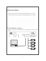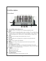
1
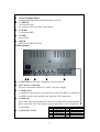
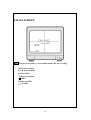
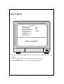
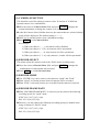
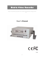
Mobile Video Recorder Thank you for purchasing our product. Please read this User*s Manual before using the product. User’s Manual V1.0 -1- SAFETY PRECAUTIONS CAUTION RISK OF ELECTRIC SHOCK. DO NOT OPEN! CAUTION : TO REDUCE THE RISK OF ELECTRICAL SHOCK, DO NOT OPEN COVERS. NO USER SERVICEABLE PARTS INSIDE. REFER SERVICING TO QUALIFIED SERVICE PERSONNEL. This label may appear on the bottom of the unit due to space limitations. The lightning flash with an arrowhead symbol within an equilateral triangle is intended to alert the user to the presence of uninsulated “ dangerous voltage” within the product’s enclosure that may be of sufficient magnitude to constitute a risk of electric shock to persons. The exclamation point within an equilateral triangle is intended to alert the user to presence of important operating and maintenance (Servicing) instructions in the literature accompanying the appliance. WARNING : TO PREVENT FIRE OR SHOCK HAZARD, DO NOT EXPOSE UNITS NOT SPECIFICALLY DESIGNED FOR OUTDOOR USE TO RAIN OR MOISTURE. Attention: installation should be performed by qualified service Personnel only in accordance with the National Electrical Code or applicable local codes. Power Disconnect. Units with or without ON-OFF switches have power supplied to the unit whenever the power cord is inserted into the power source ; however, the unit is operational only when the ON-OFF switch is in the ON position. The power cord is the main power disconnect for all unites. -2- Contents 1.OVERVIEW ..............................................................................................................4 (1)ABOUT THIS MANUAL ...........................................................................................4 (2)THE MENU SYSTEM ..............................................................................................4 (3)FEATURES ..............................................................................................................5 2.INSTALLATION ......................................................................................................6 (1)CAMERA&MONITOR CONNECTION .....................................................................6 (2)SENSOR CONNECTION ...........................................................................................7 (3)POWER CONNECTION ............................................................................................7 3.UNIT DESCRIPTION..............................................................................................8 (1)FRONT PANEL........................................................................................................8 (2)REAR PANEL..........................................................................................................9 4.MAIN SCREEN ......................................................................................................10 5.MAIN MENU .......................................................................................................... 11 (1)CAMERA SELECTION ...................................................................................12 (2)RECORD SELECT ...........................................................................................12 (3)RECORD MODE ..............................................................................................12 (4)RECORD FRAME RATE ................................................................................12 (5)VIDEO QUALITY ............................................................................................13 (6)RECORD SCHEDULE.....................................................................................14 (7)SUB MENU ........................................................................................................14 (8)HARD DRIVE SETUP......................................................................................16 (9)SENSOR SETUP ...............................................................................................17 6.PLAY ........................................................................................................................18 7.SPECIFICATION ...................................................................................................19 8.TEST REPORT OF VIBRATION.........................................................................20 -3- 1.OVERVIEW (1)About this Manual This manual describes the procedures for operating the four-channel digital video recorder (DVR). This manual describes each function using text instruction and Graphic User Interface (GUI). Appendix A contains quick reference guide for front panel controls. (2)The Menu System The menu system is used to configure the Mobile Video Recorder and gives control over recording resolution, camera sequencing, timer settings and alarm triggering and alarm triggered recording. There is also access to monitor options and password functions along with many other parameters. A menu can contain the following types of entry: Sub-menu heading - press the ENTER key and the sub-menu is entered. Function - press the ENTER key and the function is performed (e.g. Reset System). Selection - press the left and right menu keys to cycle through the choices. Any changes made to the menu system have immediate effect on the operation of the system. Any changes to a menu are stored after 3 seconds of no keys being pressed. The menu is stored on the hard disk. To reset press ”PAUSE” button 5 times in the normal view mode. Beware that all the information will be lost. After reset the password will be set as the default value (111111). All the menus listed are shown in their factory default state. -4- (3)Features Your four-channel color DVR provides real-time live playback monitoring, and recording features, with quad-mode processing or each-mode recording. Also offers the following features: ․NTSC/PAL Compatible (Selector Switch). ․Cost effective Digital Video Solution. ․Compact Size. ․User-friendly Menu System. ․Flexible Recording Rate: - Quad Mode Max.: 30fps (NTSC); 25fps (PAL) - Each Mode (for 4CH video input) Max.: 7.5field/ NTSC; 6.25field/ PAL. ․Supporting Function: Non-stop Auto Recording, Sensor Recording and No Recording Functions. ․Watch-Dog Function: Auto Returns to the Original Operation when Power Recovers from Failure. ․4-Channel Alarm Input, 1-channel Alarm output, and an Internal Buzzer. -5- 2.INSTALLATION You have to DIY four holes and fix the mobile DVR by the screws in the car before Using it. You can refer the file describing the hole size or below. (1)Camera&Monitor Connection Connect camera to the CAMERA INPUT(1~4) and Monitor on the rear panel of unit. -6- (2)Sensor connection Connect sensors to terminal 10 Pin as specified below. You can connect dry-contact type sensors. In case of sensors with output(5V system),GND of sensor must be connected to GND of DVR unit and signal line to alarm input from 1 to 10 as shown in following figure. Short-circuit between any of 1 from 10 and GND is recognized as an alarm. (3)Power connection Connect D/C 10V~40V power to the power connection on the rear panel of DVR unit. -7- 3.Unit Description (1) Front Panel 7 8 9 10 11 12 13 14 15 6 18 5 1 2 3 4 17 1~5.CAMERA Number Button (1-4) Select the camera (1-4) image in live recording and playback mode. 6.REC ․Press this button to begin Recording (video recording). The recording channel indicator next to CH1,CH2,CH3 and CH4 will appear in the center of the screen notifying the user which camera is running during recording period. 7.REV Selects the previous image in the playback mode (reverse). 8.STOP Stops recoding in the recording mode or playback in the playback mode. 9.PAUSE Display screen is pause while playback. 10.F.F Selects the next image in the playback mode (fast forward speed of 4X). 11.PLAY : To playback recorded images. When Playback key is pressed, you will be asked to input the time period (time of previous recorded video) for searching purpose, than press the Playback key again to view the playback videos. 12.MENU ․Displays the Main menu. ․Begins the menu mode. ․Exit or closes the current menu. 13.Up&Lift Button Navigates through menus, direction button of O.S.D. -8- 14.Down &Right Button Navigates through menus, direction button of O.S.D. 15.ENTER To Select the item. To confirm a selection in the menu system. 16. H.D.D To draw out HDD 17.PWR Power LED 18.LED (REC/PLAY/MENU/STOP) (2) Rear Panel no p q r 1.NTSC/PAL:NTSC/PAL Compatible (Selector Switch). 2.D/C Power Connection The unit is furnished with a DC 10~40V/ 4A power supply. 3.VIDEO OUT A composite video output is provided on the Video Out BNC for connection to a B/W or color video monitor (also supports VCR connection). 4.VIDEO IN Four video inputs are provided for video source connections using standard BNC connectors. The video inputs accept monochrome or color composite NO. PART NO. PART video signals. 5.Alarm IN:ALARM 1 2 3 4 5 -9- GND ALARM1 INPUT GND ALARM2 INPUT GND 6 7 8 9 10 ALARM3 INPUT GND ALARM4 INPUT RELAY OUT-COM. RELAY OUT-N.O. 4.MAIN SCREEN OFF Note: From previous picture, you can understand CH3 not recording CH3:Not Recording EACH: Record Mode (S):Slave HDD (T):Record Schedule ( ):REC (M):Master HDD (一):NO REC - 10 - 5.MAIN MENU MAIN MENU >CAMERA SELECT RECORD SELECT RECORD MODE RECORD FRAMERATE VIDEO QUALITY RECORD SCHEDULE SUB MENU HARD DRIVE SETUP SENSOR SETUP 1234 1234 EACH 30 NORMAL PRESS(< >), THEN (ENTER) PRESS (MENU) TO EXIT You can see the arrow(>)symbol on screen in front of the current function to be selected. Press(<) or (>) on the front panel to change the function mode. Press (ENTER) button for executing the selected function. - 11 - (1) CAMERA SELECTION This function is used for setting up camera views. It consists of 16 different optional camera view combinations. nMove the cursor to Camera Select field, and press ENTER to display the system information to change the camera view combinations. o After the Camera Select field has been set, the cameras that are selected (during setup) will be displayed (The default setting is “----“). pThere are 16 optional camera view combination settings. qPress MENU to exit Camera Select. For example: 1) When you choose (- - - -), all cameras will be disabled. 2) When you choose (1 2 3 4), all cameras will be operational. 3) When you choose (- - - 4), only cameras 4 will be operational. 4) When you choose (1 2 - 4), only cameras 1,2 and 4 will be operational. (2) RECORD SELECT This menu selects the cameras used in the “Each” mode recording setup. n Move the cursor to Record Select field, and press ENTER to change the combinations of cameras that will recorded. o Press MENU to exit the Record Select. (3) RECORD MODE n The “ENTER” key can be used to select between “Quad” and “Each” oWhen “Quad” is selected pictures from all cameras will be recorded. pWhen “Each” is selected, pictures are recorded from the camera(s) selected. (4) RECORD FRAME RATE nWhen “RECORD FRAME RATE” is selected, you may choose the following recording speeds for “Quad” mode: NTSC:30,15,10,7,5,4,3,2,1fps. PAL :25,12,8,6,4,3,2,1fps. oLikewise, you may choose the following recording speeds per channel when using 4 cameras in “EACH” mode: NTSC:30,15,10,7,5,4,3,2,1fps. PAL :25,12,8,6,4,3,2,1fps. - 12 - Recording Capacity( 80GB Hard Drive) Condition Video Signal Display format 30fps 15fps 7fps 1fps Video Quality NTSC QUAD SCREEN FULL SCREEN HIGH 36HOURS 72 HOURS 144 HOURS 1080 HOURS NORMAL 48 HOURS 96 HOURS 192 HOURS 1440 HOURS BASIC 58 HOURS 116HOUS 232 HOURS 1740 HOURS HIGH 64 HOURS 128HOURS 256 HOURS 1920 HOURS NORMAL 90 HOURS 180 HOURS 360 HOURS 2700 HOURS BASIC 112 HOURS 224 HOURS 448 HOURS 3360 HOURS 25fps 12fps 6fps 1fps HIGH 38 HOURS 76 HOURS 152 HOURS 950 HOURS NORMAL 48 HOURS 96 HOURS 192 HOURS 1200 HOURS BASIC 60 HOURS 120 HOURS 240 HOURS 1500 HOURS HIGH 62 HOURS 124 HOURS 248 HOURS 1550 HOURS NORMAL 90 HOURS 180 HOURS 320 HOURS 2250 HOURS BASIC 118 HOURS 236 HOURS 472 HOURS 2950 HOURS Condition Video Signal Display format Video Quality PAL QUAD SCREEN FULL SCREEN (5) VIDEO QUALITY This function provides for the adjustment of the image quality: LOW/ NORMAL / HIGH nMove to the Record Frame Rate field, and press ENTER . oSet the recording image quality from the three options. pPress MENU to exit the Video Quality. NOTE: Higher quality images require more recording (HDD storage) space. Everything else being equal, HIGH quality will require30%more storage than NORMAL quality and LOW quality requires up to 30% less than NORMAL. - 13 - (6) RECORD SCHEDULE This function enables recording on a predetermined schedule. n Move to the Record Schedule field, and press ENTER . o Optional settings are offered to allow different camera setups. p “T” = Automatic continuous recording. “S” = Sensor recording. Recording will only be done when a trigger is activated, (the Record button must be on for standby mode). “–" = No recording. q Press MENU to exit the Record Schedule. PROGRAMMED RECORD +S T T T T T T T T T T T T T T T T T T T T T T T T+ | | | | | | | | | 0 3 6 9 12 15 18 21 24 (7) SUB MENU SUB MENU PASSWORD CHANGE TIME SET PRESS(< >), THEN (ENTER) PRESS (MENU) TO EXIT nPassword Change (A password is required to format (erase) the hard drive). 1)When you select, “PASSWORD CHANGE”, a password input menu replaces the “Sub Menu”. (Initial Password: 111111). - 14 - c You will, then, be asked to input the following 3 pieces of information: CURRENT PASSWORD:-----NEW PASSWORD: -----PASSWORD CONFIRM: -----d When the new password is accepted, the board will flash the following screen message: ”Password changing !!!” e The message will blink 5 times. f Then the “SUB MENU” will return. If the password was not accepted, you will receive a message that informs you. and the “SUB MENU” returns. You may try again by repeating the same steps. ~Notice: Use the camera number buttons on the front panel to input your number.. oTIME SET Below is a screen shot of the “TIME SET” screen: TIME 2003/01/01 01:01:00 PRESS(<,>), THEN (SELECT) PRESS (MENU) TO EXIT Please input the “TIME SET” When you want change time &date Use the” ” and “ “ button on the front panel to move the” ^ “cursor below the number back and forth .Then use the ENTER button to change the numeric values of date & time. When you press the “Menu” button, your setting are memorized by the board. - 15 - (8) HARD DRIVE SETUP This menu displays the size of the hard disk and the remaining storage space. HARD DRIVE SETUP OVERWRITE ENABLED YES MASTER HDD SIZE 39266MB MASTER HDD SIZE USED 0MB % MASTER HDD SIZE FORMAT SLAVE HDD SIZE N/A SLAVE HDD USED N/A SLAVE HDD FORMAT n Move to the Hard Drive Setup Menu and press ENTER . o In the Overwrite Enabled field, select either YES or NO. For example, when the hard drive is full: YES will continue recording by overwriting the oldest recorded image. NO will stop recording when the Hard Drive (HDD) is full. pIn the Hard Drive Setup Menu, select Hard Drive Format in order to format (or erase) the hard disk. The correct password must be entered to enable permission to format the hard disk. For example: PASSWORD INPUT(6): -----NOTE: Password Correct will be displayed, when the password has been entered correctly or Password Incorrect will be displayed if an incorrect password has been entered. - 16 - (9) SENSOR SETUP SENSOR SETUP SENSOR RECORD TIME 30 ALARM OUT TIME 00 CHANNEL-1 CHANNEL-2 CHANNEL-3 CHANNEL-4 NOT INSTAL LLED NOT INSTAL LLED NOT INSTAL LLED NOT INSTAL LLED PRESS(< >), THEN (ENTER) PRESS (MENU) TO EXIT nSensor Record Time This function provides the setup of sensor recording time after a sensor device has been triggered. Move the cursor to SENSOR SETUP and press ENTER . Select the SENSOR RECORD TIME by pressing ENTER again. The Sensor Record Time is configured at 5-second intervals from 5 Sec. to 30 Sec. by using the front panel arrow buttons. Sensor recording is only active during the time period when the function S has been set on the Record Schedule menu. oAlarm Out Time Once a sensor / alarm trigger is received, the duration of the output relay can be set to: 0, 5, 10, 15, 20, 25, 30 seconds, or continuous (CONT). The relay has a normally open contact, and should be limited to circuit loads less than one amp. NOTE: The alarm output will only function during hours that are set to “S” in the RECORD SCHEDULE menu. p Channel 1-4 (Open or Not Installed) Any channel sensor channel that you wish to be active must be set to “OPEN”. A trigger to a particular channel will activate recording of that channel only. q Press MENU to exit SENSOR SETUP. - 17 - 6.PLAY SEARCH TIME HARD DRIVE:MASTER 13/06/05 13:52:34~13/06-05 13:52:36 PRESS(<,>), THEN (ENTER) PRESS (MENU) TO EXIT >01 TIME 一頁7筆 07 nPress the PLAY button to display the start times of recordings that are available to play. o Press the PLAY button again to start playback of your most recent recording. You can play back a recording from a specific event by moving the cursor (>) and pressing the PLAY button. When the cursor is in front of an event time, the start and end time of the event is shown at the top of the screen. pPress the STOP button if you want to stop playback. qDuring playback, press the PAUSE button to pause playback. NOTE: Pressing the FF button will move the cursor to the top of the screen where a specific time search can be entered using the < > and ENTER buttons. - 18 - 7.Specification Item Description Remarks NTSC/PAL Video Input Format 4CH Composite Video Input Channel 1CH Composite Video Output Channel Display Frame Recording Frame Rate NTSC PAL NTSC PAL 120 fields/s 100 fields/s Max.30fps(Quad) Max.25fps(Quad) 4*30 fields/s 4*25ields/s NTSC Max.7.5fields/s(Each Mode) Each Mode=Max fields/s/number of video sources Max.6.25fields/s(Each Mode) Each Mode=Max fields/s/number of video sources Continuous,manual,event,progra mmed NTSC:720*480 PAL:720*576 NTSC:320*136,640*272 PAL:320*136,640*272 Modified MJPEG (12-20K bytes/frame 30 fields/s(per recording channel) (Quad Mode) Recording Frame Rate (Each Mode) PAL Recording Mode Display Resolution Recording Compression Format (each channel) 80GB(Removable) HDD HDD,VCR Back-up(Archive Device) Search Mode F/Screen Time,date,camera Yes 4Input,1 Output Sensors,Alarm CE/FCC EMC Operation temperature 41° f~104°f (5 ~40 ) Operation humidity Weight Power supply LESS THAN90% 4KG DC10~40V /4A - 19 - 25fields/s(per recording channel) Quad:640*224(total) Each hannel:640*224 Low:12K BYTES/FRAME Normal:15K High:20K 8.Test report of Vibration Test No. Result 1. 5~300HZ 0.9G(peak) Z Direction(up .down) 1 oct/min 2 sweeps PASS 2. 5~300HZ 1.0G(peak) Z Direction(up. down) 1 oct/min 2 sweeps PASS 3. 5~300HZ 1.0G(peak) X .Y Direction(plane) 1 oct/min 2 sweeps PASS 4. 5~300HZ 1.4G(peak) X .Y Direction(plane) 1 oct/min 2 sweeps FAIL 5. 5~300HZ 1.4G(peak) X .Y Direction(plane) 1 oct/min 2 sweeps Damper breakdown DATA PASS 6. 5~300HZ 1.4G(peak) X .Y Direction(plane) 1 oct/min 2 sweeps PASS - 20 -