1
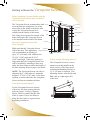
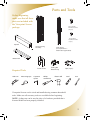
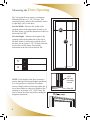
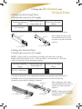
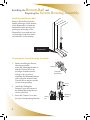
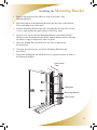
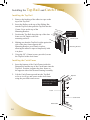
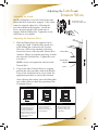
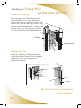
Installation Manual for
For Right and Left Hinged Doors
Durable. Reliable. Attractive.
For door openings up to 36” (914 mm) wide
and 80 9/16” (2,047 mm) high
Quick and
Easy to Size
and Install
Congratulations and
thank you for purchasing
Viewpoint!
The Viewpoint Screen is designed and manufactured by Seiki Screen
Systems, the world’s largest manufacturer of retractable screens. Phantom Screens, North America’s leading brand of retractable solutions, is proud to bring you these innovative products. Thanks to
rigorous design and product testing, the Viewpoint Screen will provide
years of dependable operation. Plus, it comes with a factory-supplied
limited lifetime warranty on all parts against manufacturer’s defects.
Viewpoint was designed for easy sizing and installation. This Installation Manual provides a step by step guide through the entire process.
Any questions? Contact
our Help Line, Toll Free at
1-877-446-7180.
Index
Getting to Know the Viewpoint Screen ................ 4
Parts and Tools ...................................................... 5
Measuring the Door Opening ............................... 6
Cutting the Horizontal and Vertical Parts .................................................. 7
Installing the Bottom Rail and Preparing the Screen Housing Assembly .............. 8
Installing the Mounting Bracket .......................... 9
Installing the Top Rail and Catch Frame ................................................. 10
Adjusting the Latch
and Tension Wires ............................................... 11
Attaching the Fixing Strip and Installing the Clips ....................................... 12
Service and Maintenance Hints .......................... 13
For installation on a double hinged door (French Doors), you
will need: two Viewpoint Screens and one Double Door Kit.
Please refer to the Installation Manual within the “Double
Door Kit” prior to starting.
The Viewpoint Screen is not intended for installation on a
Sliding Patio Door.
Getting to Know the Viewpoint
Before beginning, become familiar with the
Viewpoint Screen and the door on which it
will be installed.
Screen
Rollers
The Viewpoint Screen accommodates both Top Rail
in-swing and out-swing doors. In-swing
doors open to the inside of the home and
Sliding Bar
require the Viewpoint Screen to be installed on the outside of the home. Out-swing doors open to the outside of the Latch
home and require the Viewpoint Screen to be installed on the inside of the home.
Does the Viewpoint Screen fit the Door Opening?
Door Frame
Corner Cover
Mesh
Mounting Bracket
Clip
Fixing Strip
Latch Hole
Make sure that the Viewpoint Screen Catch Frame
will fit the door. This application Sliding Bar Bottom Cap
will accommodate an opening of up to 36” (914 mm) wide, and between 76 9/16” (1,947 mm) and 80 9/16” (2,047 mm) high. If the door opening is
larger than that, the Viewpoint Screen can
still be installed by attaching a filler strip
under the door frame to reduce the height of
the door opening. Refer to page 6 for details.
NOTE: The Viewpoint Screen can only be
shortened by 4” (100 mm) to a minimum
height of 76 9/16” (1,947 mm). If the door
opening is smaller than this, the Viewpoint
Screen will not accomodate the door.
Tension Wire
Bottom Rail
Is there enough Mounting Surface?
The Viewpoint Screen is a recess
mount screen that installs on the
inside surface of the door frame.
A minimum Mounting Surface of
1 3/4” (45 mm) is required. This
Mounting Surface must be flat and
flush, and at a right angle (90˚) to the door.
Is the Door Opening Square?
For the Viewpoint Screen to operate effectively, the door opening must be perfectly square. Using a Carpenter
Square, check to ensure that the door
frame is square. If not, use shims to
bring the door frame to square before
beginning installation.
4
Mounting Surface
Viewpoint Screen
me
over
Parts and Tools
Before beginning,
make sure that all these
parts are included with
the Viewpoint Screen
package.
5/8” (16 mm)
Pan Head Screws
(12 pcs.)
g Bracket
1/2” (12 mm)
Flat Head Screws
(2 pcs.)
ip
Wire
Top Rail
Screen Housing
Assembly
Rail
Catch Frame
(not required for a
double door application)
Bottom Rail
Required Tools
Hack saw
Measuring tape
Corner Cover
Carpenter
square
Philips
screwdriver
Sliding Bar
Bottom Cap
Clips (5 pcs.)
Electric drill
Level
Pen
Viewpoint Screens can be sized and installed using common household
tools. Make sure all necessary tools are available before beginning.
NOTE: A chop saw can be used in place of a hacksaw provided that a bi-metal blade has been properly installed
5
Measuring the Door
Opening
The Viewpoint Screen requires a minimum
Mounting Surface of 1 3/4" (45 mm). This
mounting surface must be flat and flush, and at
a right angle (90º) to the door.
For the Width - Measure the width of the
opening between the right and left surfaces of
the door frame, record this dimension in the box
below labeled “W”.
For the Height – Measure the height of the opening between the underside of the top of
the door frame (or filler strip), and the top of
the door sill at a point 1 3/4" (45 mm) from the
front surface of the frame. Record this dimension in the box below labeled “H”.
W
=
H
=
NOTE: If the height of the door opening is
greater than the maximum height requirement,
it is still possible to install the Viewpoint
Screen. Simply attach a filler strip under the
top of door frame to reduce the height of the
opening to at least 80 9/16" (2,047 mm). Be
sure to attach the filler strip before taking the
height measurement.
6
W
H
A
1 3/4”
(45 mm)
mounting
surface
Door Sill
Cutting the Horizontal and
Vertical Parts
Cutting the Horizontal Parts
Calculate the correct cut off Lengths.
Maximum Opening
Width
36” (914 mm)
Subtract inside door
frame width “W”
Enter Cut off Length
Below
-
=
Cut from each part the cut off length provided by the calculation performed above.
Top Rail
Bottom Rail
After cutting any part of the
Viewpoint Screen, use a file
to remove any burrs from the
surfaces.
Cut Off Length
Cut Off Length
Cutting the Vertical Parts
Calculate the correct cut off Lengths.
NOTE: Cutting of the Screen Housing Assembly must take place from the bottom of the unit, note the “Cut” / “No Cut” labels. No more than 4” (100 mm)
can be cut from the Screen Housing Assembly.
Maximum Opening
Height
80 9/16” (2,047 mm)
Subtract inside door
frame height “H”
Enter Cut off Length
Below
-
=
Cut from each part the cut off length provided by the calculation performed above.
Do NOT remove the tape that keeps the components of the Screen Housing Assembly secure until all cutting is complete.
After cutting any part of the Catch Frame
Viewpoint Screen, use a file to remove any burrs from the surfaces.
Cut off Length
Screen Housing Assembly
Cut off Length
NOTE: Safety glasses should be worn at all times during the cutting process.
7
Installing the Bottom Rail and
Preparing the Screen
Housing Assembly
Installing the Bottom Rail
Remove the backing from the
double sided tape on the bottom
of the Bottom Rail. Attach the
Bottom Rail onto the door sill,
placing the front edge of the
Bottom Rail even with the face
or front edge of the door frame
on both sides of the opening.
Bottom Rail
Preparing the Screen Housing Assembly
1.
Before installing the Screen Housing Assembly, rotate the Mounting Bracket so that the Tension Wires are no longer wound around it. Failing to do so prior to installing the Mounting Bracket will restrict the motion of the Tension Wires and prevent the screen from operating.
2. Attach the Sliding Bar Bottom Cap to the bottom of the Sliding Bar using the two screws provided.
3. Insert the Corner Cover onto the top of the Mounting Bracket.
8
Sliding Bar
Sliding Bar
Bottom Cap
Corner
Cover
Sliding
Bar
Mounting
Bracket
Installing the Mounting
Bracket
1. Remove the backing of the adhesive strip on the back of the Mounting Bracket.
2. Insert the bottom of the Mounting Bracket into the track of the Bottom Rail on the hinge side of the door.
3. Push the Mounting Bracket upwards, ensuring that the top of the Corner Cover is tight against the upper portion of the door frame.
4. Using a level, ensure that the Mounting Bracket is positioned plumb. Then press the Mounting Bracket firmly against the door frame, allowing the adhesive tape to temporarily hold it in place.
5. Move the Sliding Bar and Mesh off to the side as indicated in the illustration.
6. Using the provided screws, secure the Mounting Bracket to the door frame.
7. Return the Sliding Bar and Mesh back to its original position, in front of the Mounting Bracket.
Door Frame
(Top)
Sliding Bar
Mounting Bracket
Door Frame
9
Installing the Top
Rail and Catch Frame
Installing the Top Rail
1. Remove the backing of the adhesive tape on the top of the Top Rail.
2. Insert the Rollers at the top of the Sliding Bar into the Top Rail, then push the Top Rail into the Corner Cover on the top of the Mounting Bracket.
3. Position the Top Rail along the top of the door frame at a 90º angle to the side mounting surfaces.
4. Push
Corn into the
er Co
ver
Insert Rollers
as shown
Corner Cover
Making sure that the Top Rail is tight against the side of the door frame opposite the Mounting Bracket, press firmly in place, allowing the adhesive tape to temporarily hold it in place.
Mounting Bracket
5. Using the 5/8” (16mm) screws provided, secure the Top Rail to the door frame.
Installing the Catch Frame
1. Insert the bottom of the Catch Frame inside the Bottom Rail and the top of the Catch frame into the Top Rail. Position it against the door frame on the opposite side of the Screen Housing Assembly.
2. Lift the Catch Frame upward into the Top Rail as far as it will go, and secure to the door frame using the provided wood screws.
Top Rail
Push up the top of the
Catch Frame all the way
into the Top Rail
Latch
Catch Frame
Door Frame
10
me
Adjusting the Latch and
Tension Wires
Adjusting the Latch
Pull the Sliding Bar over to the Catch Frame and
ensure that the Latch can be engaged. If the Latch
cannot be engaged, adjust it by following the procedure shown in the diagram. Loosen the
screw, adjust the height of the Latch until it
engages with the Sliding Bar. Tighten the screw,
careful not to over tighten.
Loosen the screw
to move up and down.
Adjusting the Tension Wires
1. Slide the Sliding Bar to the opposite end to engage the Latch. Push the entire mesh over to the Sliding Bar so that only the Tension Wires are visible in the opening of the door. Loosen the screw of the top most Tension Wire Adjuster. Slide it up or down until snug, without any sag in the Tension Wire. Tighten the screw to secure it.
NOTE: do not over tighten the tension on the Tension Wire.
2. If any of the other Tension Wires are sagging, perform the same procedure with each adjuster. If any of the situations below occur, follow the appropriate procedure to correct the situation. After adjusting the tension, move the Sliding Bar two or three times to check the operation of the Viewpoint Screen.
Situation #1
Situation #2
Solution #1
Keep the topmost Tension
Wire Adjuster fixed, loosen
the remaining Adjusters.
Starting from the bottom
Adjuster, adjust the tension of
each wire to remove the gap
as well as any sag in the
Tension Wires.
Tension Wire
Adjuster
Screw
Situation #3
Gap
Gap
Tension Wire
Solution #2
To correct this situation,
reverse the steps in
Situation #1 starting from
the top Adjuster.
Loose Tension Wire
Solution #3
Tighten the tension of the
loose Tension Wire to the
same tension as the other
Tension Wires.
11
Attaching the
Fixing Strip
and
Installing the Clips
Attach the Fixing Strip
Insert one edge of the Fixing Strip into the
Mounting Bracket on an angle, beginning at
the top, and working toward the bottom. Again
from the top, press the other edge of the Fixing
Strip into the Mounting Bracket, working it into
position all the way to the bottom so that it is
now fully inserted into the Mounting Bracket.
Fixing Strip
Sliding Bar
Mounting Bracket
Installing the Clips
Install the Clips into the Mounting Bracket
evenly between the Tension Wires keeping the
ribbed face of the Clip facing outward.
(Refer to the diagram.)
Clip
Fixing Strip
The Viewpoint Screen Installation
is Now Complete!
12
racket
Service and Maintenance Hints
The Viewpoint Screen is designed and engineered
to be maintenance free. The following are some
helpful hints to ensure the smooth operation of the
Viewpoint Screen for years to come.
•
All moving components used in the Viewpoint Screen are manufactured from a mixture of nylon and other materials. This combination of compounds is strong, impact resistant, and self-lubricating. Do not use oil, grease, oil based sprays or lubricants on any of the components on the Viewpoint Screen. These products attract dirt and debris, and may cause the Viewpoint Screen to react abnormally. However, the periodic application of a dry silicon lubricant to the moving parts is permissible.
•
We recommend that while not in use, the Viewpoint Screen be kept in the retracted position. This will help extend the life of the screen mesh. In the retracted position, the mesh is protected and kept clean.
•
The Screen Mesh and Bottom Rail should be kept free of dirt and debris. Lightly vacuum to remove any obstructions from the Screen Mesh and Bottom Rail.
* Before installing the Viewpoint Screen, please take the time to read the installation instructions thoroughly.
13
Help Hotline
The Viewpoint Screen was designed for easy sizing and installation. This Installation Manual provides a step by step
guide through the entire process.
If there are any questions during the installation of the Viewpoint
Screen, please call toll free:
1-877-446-7180
14
Viewpoint Screen
Limited Lifetime/Non-transferable
Manufacturer’s Warranty
The Viewpoint Screen is warranted by Seiki Screen Systems to be free of manufacturer’s defects in materials or workmanship, for as long as the original purchaser owns and or resides at that residence and
that the product remains at its original point of installation. Seiki Screen Systems will repair or replace at
its discretion any component, within the terms and conditions of this warranty, which is deemed as being
defective from the manufacturing process upon proof of purchase. This warranty excludes the screen mesh.
Furthermore this warranty does not cover components damaged through improper use or installation, or if
components have been altered from their original state in a manner not otherwise prescribed in the Viewpoint Screen Installation Instructions. This warranty is strictly limited to defective components only. This non-transferable, limited warranty excludes labor, breakage or damage due to normal wear and tear, lack of maintenance (as illustrated in our Installation Instructions), or use for other
than residential applications, accidents and “acts of god”. Replacements or repairs made subject to this limited warranty are otherwise warranted for the balance of the original warranty period. Seiki Screen Systems’
liability under this limited warranty is restricted to the corrective actions as set forth herein and contrarily
repudiates all incidental and consequential damage. It is the responsibility of the consumer to notify Seiki
Screen Systems of missing components, within 30 days of the purchase of the Viewpoint Screen.
The Viewpoint Screen is designed to assist in keeping unwanted insects from the home; it is in no way
intended as a safety or security device to prevent access by individuals, animals or small children. Liability
for any damages, including but not limited to general, special, indirect, incidental, consequential, aggravated, punitive or exemplary damages, and economic loss, as well as for breach of any expressed or implied warranties, including but not limited to implied warranties of merchantability, quality and fitness for
any purpose other than as prescribed herein, is disavowed and omitted here from, to the extent that such a
disclaimer and preclusions are permitted by the laws of any particular jurisdiction.
Maintenance: Keep Bottom Rail clean and free of debris. Periodic use of silicone spray to the rollers on the
top of the Sliding Bar is recommended, do not use petroleum based lubricants.
Viewpoint Screen Designed and Manufactured by
Seiki Screen Systems
INSTALLATION INSTRUCTION MANUAL
For warranty claims
Call 1-877-446-7180
Or email: [email protected]
15
Designed & Manufactured by Seiki Screen Systems ™
Marketed and Distributed by Phantom Screens ®
Seiki Screen Systems
Call 1-877-446-7180
Or email: [email protected]
Phantom Mfg. (Int’l) Ltd.
Call 1-888-PHANTOM
Or email: [email protected]
www.seikiscreensystems.com
www.phantomscreens.com
© 2008 Phantom Mfg. (Int’l) Ltd. & Seiki Screen Systems
VI0508